Article

Early Internal Short Circuit Diagnosis for Lithium-Ion Battery Packs Based on Dynamic Time Warping of Incremental Capacity

1
Electric Power Science Research Institute, State Grid Shanxi Electric Power Company, Taiyuan 030001, China
2
School of Electrical Engineering and Automation, Harbin Institute of Technology, Harbin 150001, China
*
Author to whom correspondence should be addressed.
Batteries 2024, 10(11), 378; https://doi.org/10.3390/batteries10110378
Submission received: 2 September 2024 / Revised: 7 October 2024 / Accepted: 25 October 2024 / Published: 28 October 2024

Abstract

:
Timely identification of early internal short circuit faults, commonly referred to as micro short circuits (MSCs), is essential yet poses significant challenges for the safe and reliable operation of lithium-ion battery (LIB) energy storage systems. This paper introduces an innovative diagnostic method for early internal short circuits in LIB packs, utilizing dynamic time warping (DTW) applied to incremental capacity (IC). Initially, the terminal voltages of all cells within the LIB pack are ordered at any moment to determine the median terminal voltage, which is then used to generate the median IC curve. This curve acts as a reference benchmark that represents the condition of healthy cells in the pack. Subsequently, the DTW algorithm is utilized to measure the similarity between each cell’s IC curve and the median IC curve. Cells exhibiting similarity scores that exceed a specified threshold are identified as having MSC faults. Lastly, for the cells diagnosed with MSC conditions, a method for estimating short-circuit resistance (SR) based on variations in maximum charging voltage is devised to quantitatively evaluate the severity and evolution of the MSC. Experimental findings reveal that the proposed method effectively identifies MSC cells in the LIB pack and estimates their SRs without the necessity of a battery model, thereby affirming the method’s validity.

1. Introduction

Lithium-ion batteries (LIBs) offer advantages such as high power density and long cycle life, making them widely used in applications like electric vehicles and grid energy storage [1,2,3]. However, lithium-ion battery (LIB) systems are vulnerable to harsh external environments, operational stresses, and misuse, which can result in multiple faults that not only hasten degradation but also potentially trigger incidents such as thermal runaway [4,5]. These concerns have raised public apprehension about the safety of LIBs. Therefore, diagnosing various faults is crucial for enhancing the safety of LIBs.
Recent analyses conducted by various research organizations regarding thermal runaway events in LIBs have revealed that internal short circuits (ISCs) are a leading factor contributing to these incidents [6,7,8]. Internal short circuits in LIBs are typically triggered by mechanical damage, electrical overload, and thermal stress [9,10,11]. Mechanical abuses, such as collisions, crushes, and nail penetrations, can compromise the battery structure, causing severe deformation that leads to electrical connections between the positive and negative electrodes, thereby initiating an ISC [12,13]. Thermal abuse can lead to significant shrinkage of the separator, allowing contact between sections of the positive and negative electrodes, which in turn induces an ISC [14,15,16]. Electrical abuse can lead to the deposition of metals such as lithium on the negative electrode, forming lithium dendrites. These dendrites may eventually penetrate the separator, causing an ISC. Moreover, manufacturing defects, such as metal particle contamination and electrode burrs introduced during battery production, can also result in ISCs [17,18,19]. Internal short circuits often experience a gradual evolution phase before escalating into thermal runaway. At the initial ISC, i.e., micro short circuit (MSC), the equivalent short-circuit resistance (SR) remains high, leading to minimal changes to the battery’s parameters., which makes these faults difficult to detect [20].
Current methods for diagnosing MSCs in LIB packs can be generally divided into detection and estimation techniques. Detection methods encompass various strategies that identify and locate MSC cells within the LIB pack by analyzing voltage correlations, state of charge (SOC) correlations, and the ranking of charging voltages. For instance, Lai et al. [21] developed an early detection technique for internal short circuits based on SOC correlations. This method employs an extended Kalman filter to estimate the SOC for each cell in the battery pack. Subsequently, a moving window approach calculates the SOC correlation coefficients among neighboring cells. If the correlation coefficients between a specific cell and its adjacent cells on either side drop below a certain threshold, that cell is deemed to be in an MSC state. Additionally, Chang et al. [22] proposed the constant assumption regarding the ranking of charging voltages among cells in a battery pack, suggesting that the voltage order of healthy cells remains consistent. In contrast, the presence of an MSC leads to variations in the charging voltage ranking of the affected cell, which facilitates the detection and localization of MSC cells.
Estimation methods include those based on the mean-difference model, charging characteristics, and Coulomb counting (CC). Zheng et al. [23] employed a mean-difference model and extended the Kalman filtering algorithm to obtain the SOC deviations for each cell in the LIB pack. Decision tree analysis revealed that the SOC deviations of low-capacity cells in a series battery pack are correlated with the average SOC of the pack, whereas the SOC deviations of MSC cells are time-dependent. Mutual information was utilized to quantitatively assess the correlation between the SOC deviations of individual cells and the average SOC, enabling the differentiation between MSC cells and low-capacity cells. Ma et al. [24] selected the median cell from the voltage ranking results as the representative cell for normal cells within the LIB pack. Linear fitting of the SOC difference curve before the inflection point was used to estimate short-circuit current (SC) and resistance. The results demonstrate that this method allows for the quantitative detection of MSC faults. Charging characteristic-based methods extract features from data collected during the constant current charging phase that represents the energy consumed by the SR. SC is then calculated by observing the rate of change of these features over time [25]. CC-based methods utilize an equivalent circuit model (ECM) to establish state-space equations for the LIB. SC is integrated as a variable into these equations. The SOC and SC are then estimated using algorithms such as extended Kalman filtering and H nonlinear observers. The presence of an MSC is determined by examining the discrepancy between the SOC estimated by the observer and the SOC calculated by CC [26]. Additionally, Shen et al. [27] proposed an SR estimation method based on an ECM and adaptive filtering algorithm. Furthermore, Lei et al. [28] introduced an MSC diagnostic method based on the maximum charging voltage variation between adjacent cycles. The key distinction between these two approaches lies in the fact that the former relies on the ECM of LIBs, while the latter, essentially a data-driven method, primarily estimates SC based on changes in voltage characteristics.
In summary, current estimation methods calculate SC based on the SOC differences over time and further estimate SR. However, these methods have several limitations. Firstly, existing these approaches require the ECMs. The ECMs used for LIBs frequently do not accurately represent the internal reaction processes, as their reliability is significantly affected by the parameters of the model. As a result, the accuracy of SR estimation is constrained by the inherent precision of the model and is vulnerable to changes in these parameters. Secondly, these methods necessitate the calculation of SC and SR for each cell within the LIB pack [27]. In real-world scenarios, only a minimal number of cells within a LIB pack develop MSCs, accounting for an insignificant percentage of the overall cell count. Consequently, the indiscriminate calculation of SC and SR for every cell is inefficient and burdensome, especially in large LIB packs. Therefore, enhancing the accuracy and computational efficiency of MSC fault diagnosis in LIB packs is a critical issue that needs to be addressed.
To address the issues present in current research, this paper proposes an early ISC diagnosis method for LIB packs based on incremental capacity (IC) and dynamic time warping (DTW) distance. First, the terminal voltages of all cells in the LIB pack are ranked to obtain the median terminal voltage, from which the median IC curve is derived. This median IC curve serves as a reference standard representing the state of healthy cells within the LIB pack. Next, the DTW distance between each cell’s IC curve and the median IC curve is calculated. Cells with DTW distances exceeding a predefined threshold are diagnosed with MSC faults. For the detected MSC cells, the SC and SR are quantitatively calculated based on the variation in the end-of-charge voltage. Experimental results demonstrate that the proposed method effectively detects MSC cells within the LIB pack and accurately computes their SR, thereby quantifying the evolution and severity of MSCs.

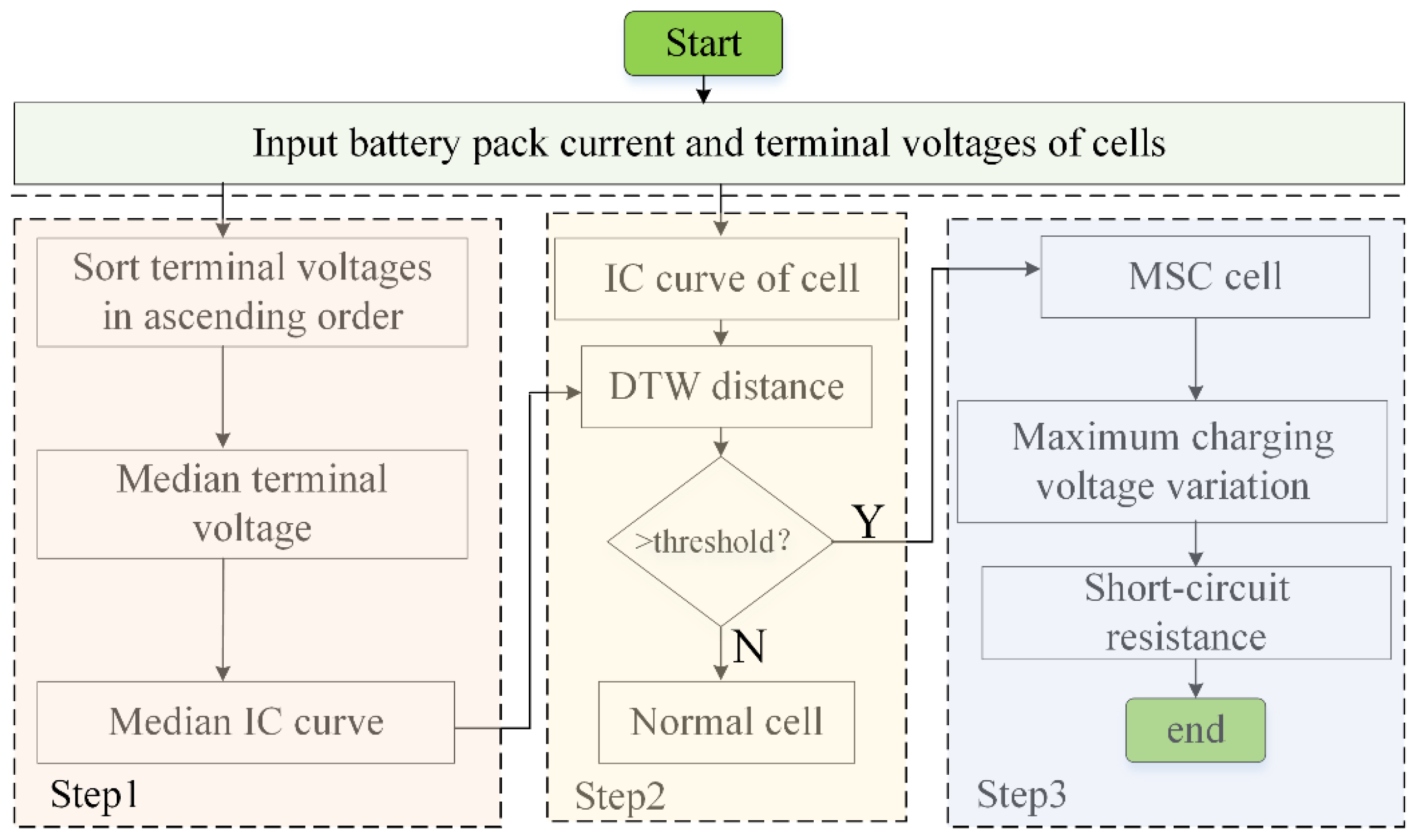
2. Diagnostic Method

The overall structure of the proposed diagnostics is displayed in Figure 1. As shown, this method encompasses three primary stages: First, the terminal voltages of all cells within the LIB pack are arranged in ascending order to determine the median terminal voltage. This median value is then utilized to derive the median IC curve, which serves as a reference standard representing the condition of healthy cells in the battery pack. Following this, the DTW distance between each cell’s IC curve and the median IC curve is computed. Cells that exhibit DTW distances surpassing a specified threshold are identified as MSC cells. Lastly, for the MSC cells identified, the SC and SR are estimated based on the changes observed in the maximum charging voltage (MCV).

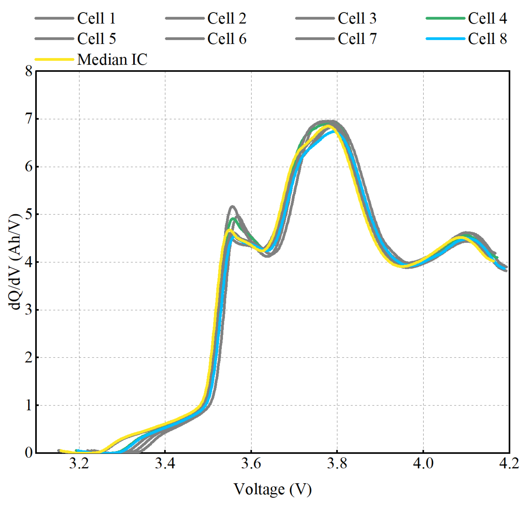
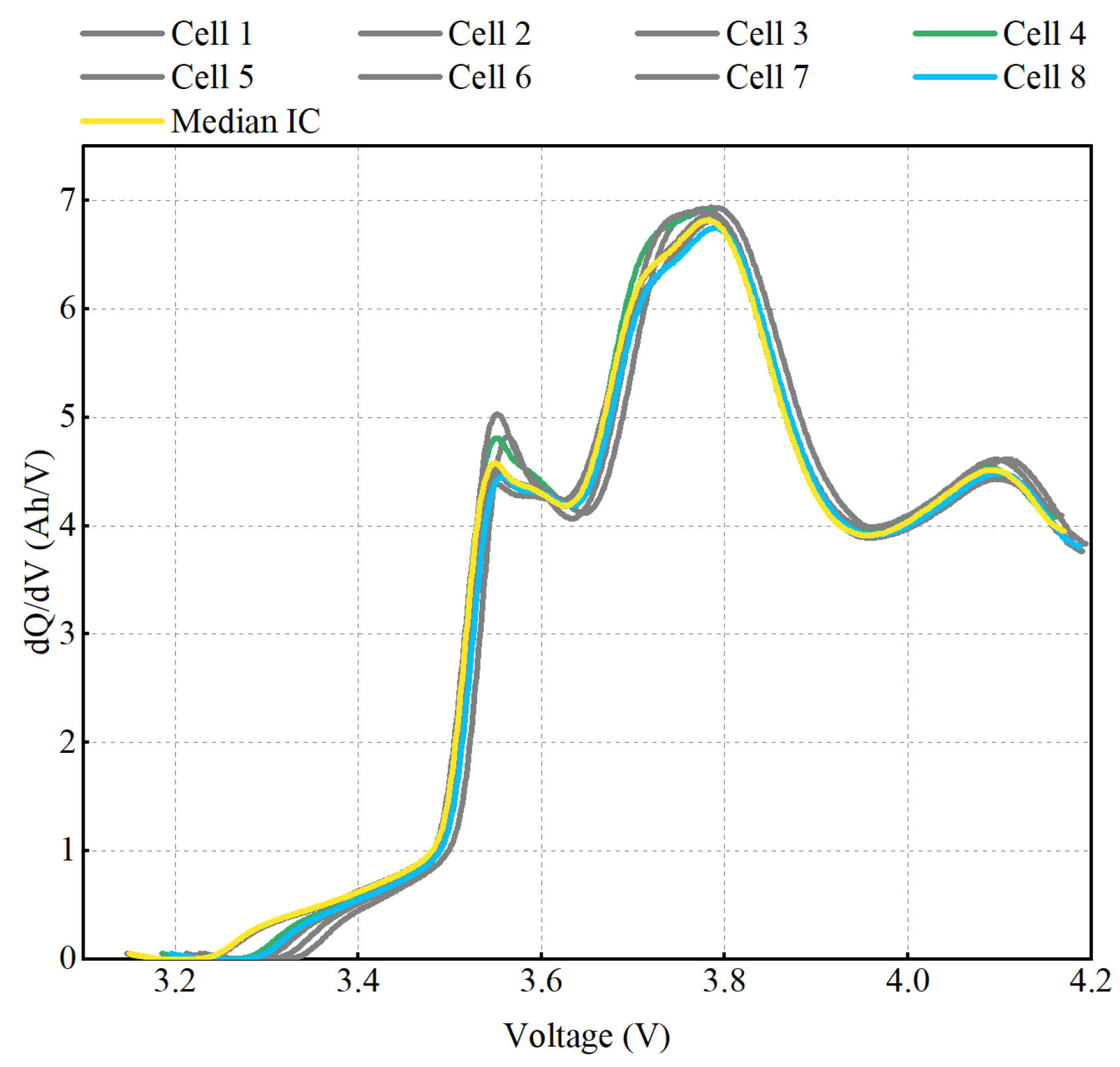
2.1. Extraction of Incremental Capacity Curves

As shown in Figure 1, once the median terminal voltage of the cells in a LIB pack is established, the corresponding median IC curve must be derived. Furthermore, the IC curve for each individual cell should be calculated based on its terminal voltage. The IC curve is typically determined using the following equation:
I C EVI = d Q d V Δ Q Δ V = Q 2 Q 1 Δ V
where Q represents the battery’s charging capacity, and V denotes the terminal voltage under constant current charging. Equation (1) illustrates the calculation of IC based on equal voltage intervals ΔV, where Q2Q1 represents the change in charging capacity within the voltage interval ΔV. In this study, the IC is calculated using the equal voltage interval method. To effectively capture the characteristics of the IC curve, ΔV is set to 1 mV.
The IC curve obtained using the aforementioned numerical differentiation method is susceptible to measurement noise. Therefore, it is essential to apply an appropriate filter to achieve a smooth IC curve. In this study, a moving average filter is employed for smoothing the IC curve. Given a time-varying signal s contaminated by noise, the moving average filter can be designed as follows:
s ^ r = 1 2 N p + 1 l = N p N p s r l
where sr represents the value of the original signal s at time r, s ^ r denotes the corresponding filtered value, and 2Np + 1 is the window size of the moving average filter, where Np is an integer. The parameter l indicates the time lag, and srl is the value of the original signal at time rl. Based on the reference [27], Np is set to 15 in this study.

2.2. Detection of MSC Cells Based on DTW Distance

This study employs DTW to measure the similarity between each cell’s IC curve and the median IC curve, thereby detecting MSC cells within the LIB pack. DTW is a robust and highly accurate method for measuring the similarity of data sequences. By warping the time axis of the data sequences, DTW aligns data points between sequences, allowing for a more precise morphological similarity assessment, even for sequences of unequal lengths [29].
We denote the median IC curve as Cmed and the IC curve of an individual cell as C:
C med = c med ( 1 ) , c med ( 2 ) , , c med ( M )
C = c ( 1 ) , c ( 2 ) , , c ( N )
where M and N represent the lengths of the median IC curve and the individual cell IC curve, respectively. The distance matrix A is constructed based on the Euclidean distance between every pair of points on the two curves and is calculated as follows:
A = d 11 d 1 N d M 1 d M N
where dij denotes the Euclidean distance between the i-th sample point cmed (i) on the median IC curve and the j-th sample point c(j) on the individual cell IC curve. The calculation formula is given as follows:
d i j = c med ( i ) c ( j ) 2 , 1 i M , 1 j N
The DTW distance D(Cmed, C) is defined as follows: it is the minimum cumulative distance value obtained by finding the optimal warping path Wbest in the distance matrix A that aligns Cmed and C. The optimal warping path Wbest can be defined by the following formula:
W best = W 1 , W 2 , , W k , , W K 1 k K , min M , N K M + N 1
Thus, the mathematical definition of DTW can be expressed as:
D C med , C = min W 1 K k = 1 K W k W k = A ( i , j ) k
where Wk represents the position of the warping path W in the distance matrix A. To ensure the uniqueness of the solution for the DTW mathematical definition, three constraints are imposed on Equation (8):
(1)
Boundary Condition: The boundary points of the optimal warping path Wbest are fixed, specifically W1 = (1, 1) and Wk = (M, N).
(2)
Monotonicity: This condition ensures the search direction for Wbest. Specifically, for a given Wk = (i, j) and Wk+1 = (i, j), it must hold that ii and jj.
(3)
Continuity: The search for Wbest can only proceed to adjacent points. Specifically, for a given Wk = (i, j) and Wk+1 = (i, j), it must hold that ii + 1 and jj + 1.
Given the three constraints, the solution to Equation (8) can be obtained using dynamic programming. The state transition equation for dynamic programming is as follows:
DTW ( i , j ) = d i j + min DTW ( i 1 , j 1 ) , DTW ( i 1 , j ) , DTW ( i , j 1 )
Based on the above process, the DTW distance between each cell’s IC curve and the median IC curve can be computed. Cells with a DTW distance below a certain threshold are considered normal. In contrast, cells with a DTW distance exceeding the threshold are diagnosed as experiencing an MSC.

2.3. Estimation of SR Based on Maximum Charging Voltage Variation

For an MSC cell, this study further estimates the SC and SR to quantitatively assess the severity and progression of the MSC. This assessment aids the battery management system in implementing targeted countermeasures.
As depicted in Figure 2, we examine the charging voltage of an MSC cell over two consecutive cycles. The figure clearly indicates that the MCV2 during the second cycle (Cycle 2) is significantly lower than the MCV1 recorded in the first cycle (Cycle 1). This decline in voltage is attributed to energy being lost due to the SR. If the MSC cell is removed from the pack after the second charging cycle and charged separately until its MCV matches that of Cycle 1, as indicated by the green dashed line in Figure 2, the additional time taken to reach this state, represented as Δt, is referred to as the remaining charging time (RCC) for the MSC cell.
In the real-world operation of energy storage LIB packs, removing an MSC cell for independent recharging to get the RCC Δt is impractical. As a result, Δt is theoretically unknown. However, it can be noted that if we project the maximum charging voltage (MCV2) from the next cycle onto the voltage curve of the prior cycle and denote the corresponding point in time as t, the time interval from t to the end of the previous cycle equals the RCC Δt. Hence, the RCC Δt for an MSC cell in the current cycle can be estimated by mapping the current cycle’s MCV onto the charging voltage curve from the preceding cycle.
Once the RCC Δt in the current cycle has been determined, the energy loss during this cycle can be calculated. This is done by multiplying Δt by the charging current of the LIB pack. The resulting energy loss, caused by the SR, is expressed as follows:
Q loss , p = I Δ t
where Qloss,p denotes the energy loss of the MSC cell at the end of the p-th charging cycle, and I represents the charging current. The rate of change of energy loss with respect to time corresponds to the SC of the MSC cell. Thus, we have the following equation:
I MSC = Q loss , p Q loss , p 1 T p T p 1
where IMSC represents the MSC current, Qloss,p denotes the estimated energy loss of the MSC cell at the end of the p-th charging cycle, Qloss,p−1 denotes the estimated energy loss at the end of the (p − 1)-th charging cycle, Tp is the time at the end of the p-th charging cycle, and Tp−1 is the time at the end of the (p − 1)-th charging cycle.
Based on the calculated SC, the SR can be further determined using the following formula:
R MSC = U M I MSC
where RMSC denotes the short-circuit resistance and UM represents the average voltage between the end-of-charge moments of two consecutive cycles. A smaller short-circuit resistance indicates a higher power dissipation due to the short circuit, which increases the likelihood of thermal runaway.

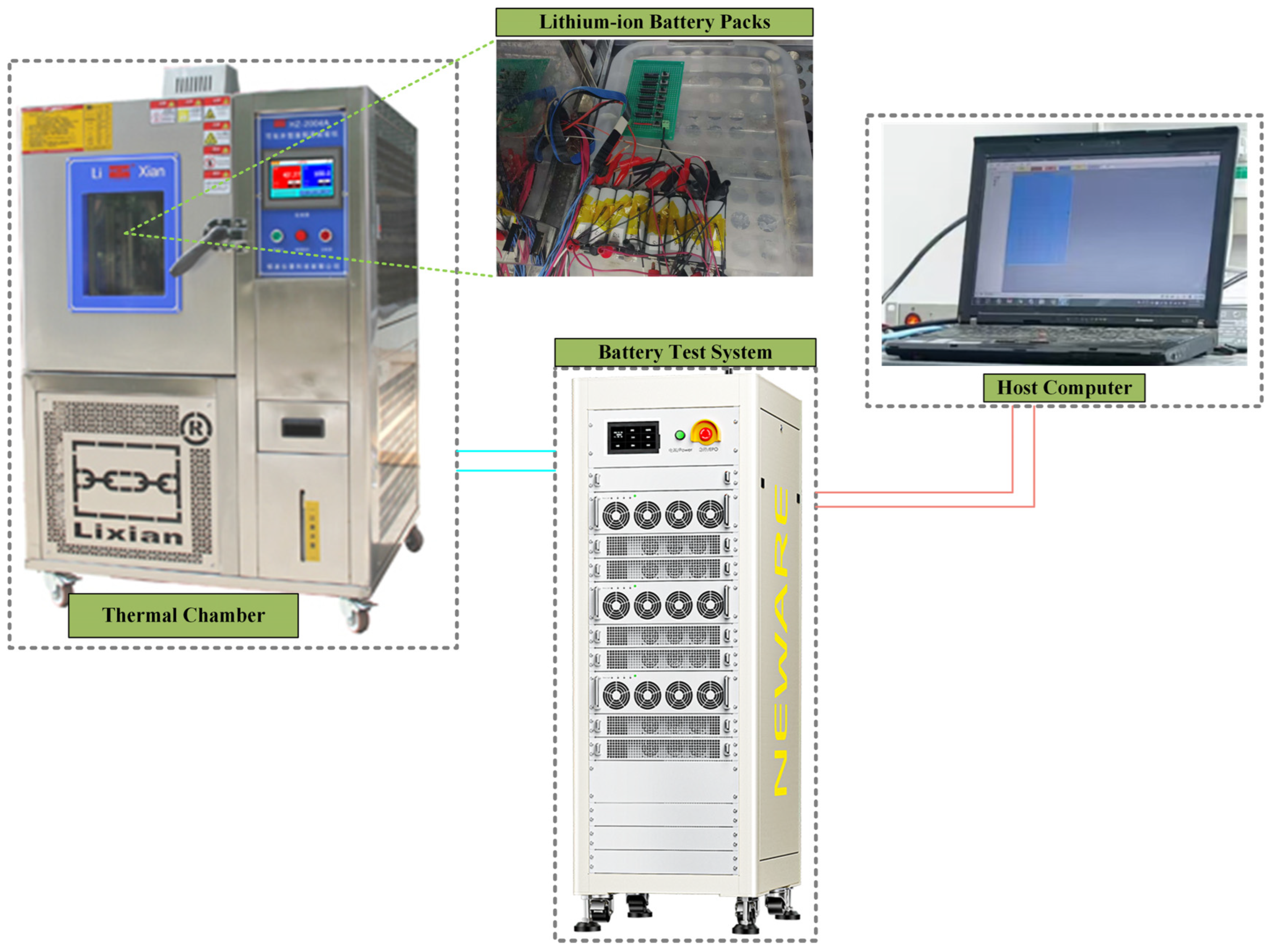
3. Experimental Section

Current techniques for triggering short circuits include mechanical damage, such as puncturing or crushing cells, temperature-sensitive materials into the battery, or promoting dendrite growth through overcharging or over-discharging. However, these methods mainly simulate late-stage ISC faults, which often result in rapid cell failure or explosion, offering limited control and repeatability. An alternative approach is to connect an external resistor in parallel with the battery terminals, which allows for a more flexible simulation of different short-circuit stages by adjusting the resistance. Since the heat generated by MSCs is minimal and effectively managed by the thermal system, thermal effects can be disregarded. MSC faults here are simulated by connecting an external resistor in parallel with the cells, enabling better control over the initiation and progression of MSCs, as well as improving both repeatability and control over the fault evolution process.
The experimental platform is illustrated in Figure 3. All tests were carried out in a temperature-controlled environment at 25 degrees Celsius. The LIB testing system was operated via a host computer, which facilitated the execution of charge and discharge cycles on the batteries. During the experiments, data was sampled at a frequency of 1 Hz. Additionally, Figure 3 includes a photograph of the series-connected battery pack situated inside the thermostatic chamber during the charge–discharge process. The experimental battery pack comprised eight cylindrical 21,700 LIBs arranged in series, with detailed specifications for each cell provided in Table 1.
In the experiment, the LIB pack was charged at a constant current rate of 0.5 C. The charging process was halted once the maximum terminal voltage of any individual cell reached the cutoff value of 4.2 V to avoid overcharging. Following the charging phase, the battery pack was subjected to a dynamic stress test (DST) discharge. Discharging was stopped when the minimum terminal voltage of any cell dropped to the cutoff value of 2.75 V, preventing over-discharge. In total, 14 charge–discharge cycles were completed. Starting from the third cycle, different SRs were connected in series and then placed in parallel across the terminals of Cells 4 and 8 to simulate MSC evolution. By activating various switches, different magnitudes of SR were paralleled across the battery terminals to mimic the initiation and progression of MSCs. A lower resistance corresponds to a higher SC, indicating a more severe fault. The specific SRs applied during each cycle are listed in Table 2.

4. Results and Discussion

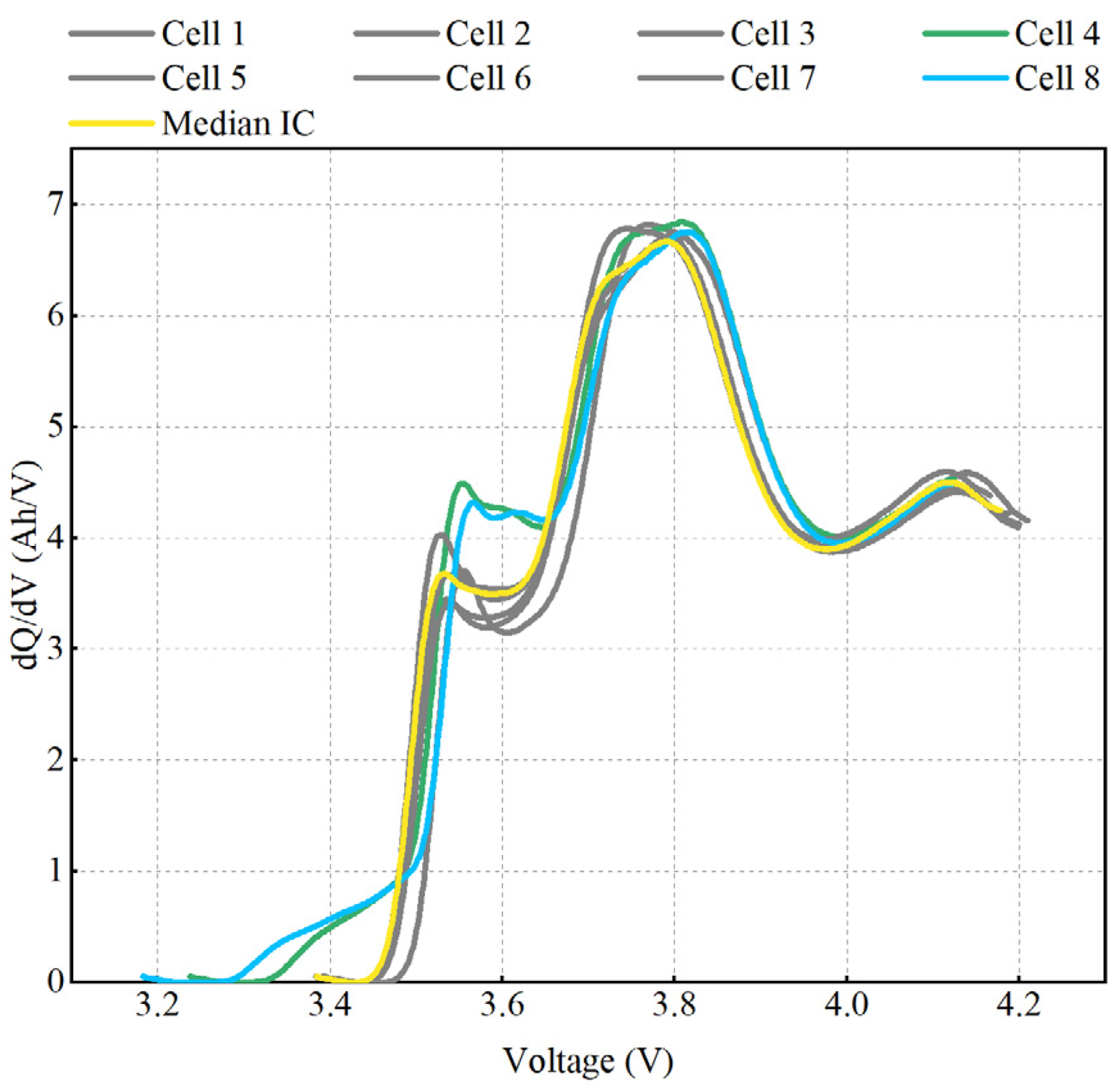
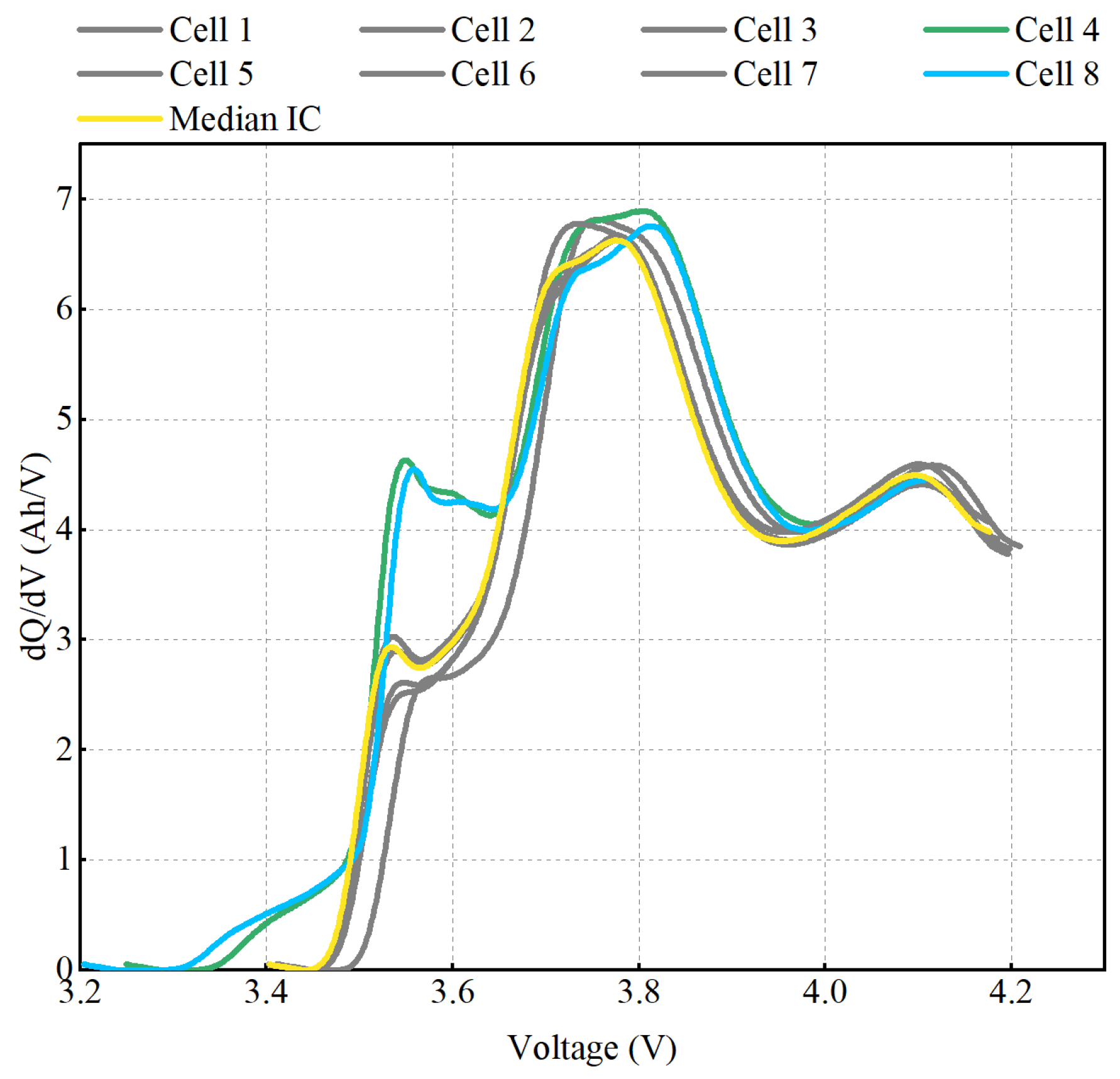
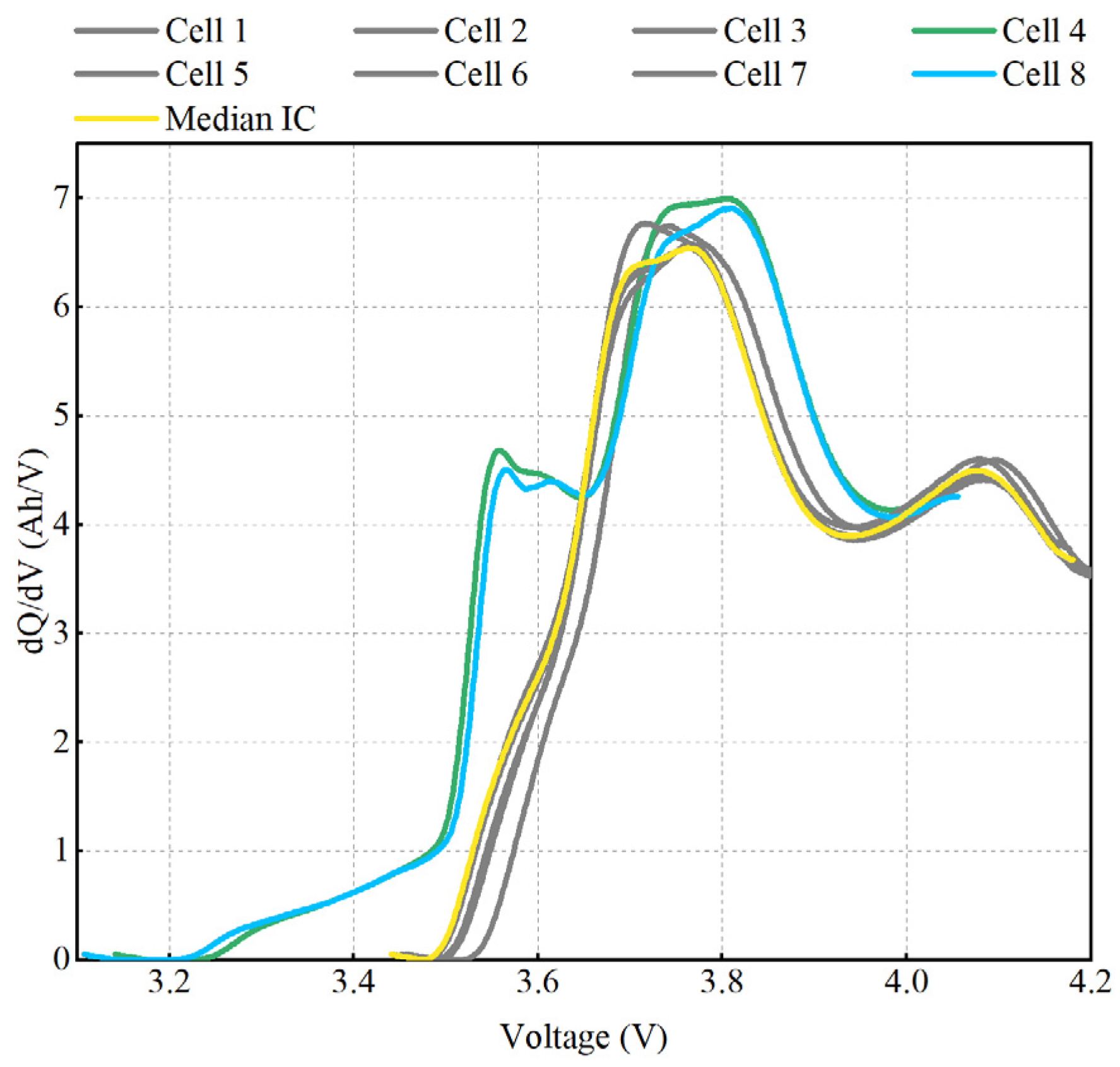
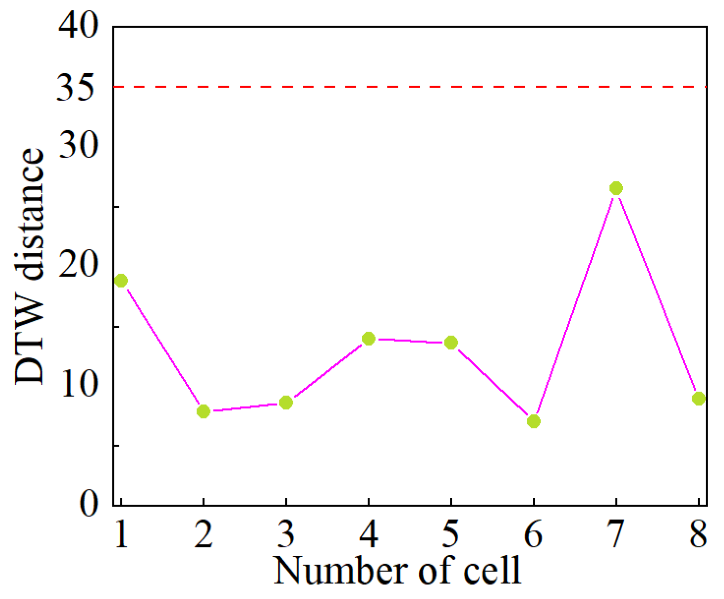
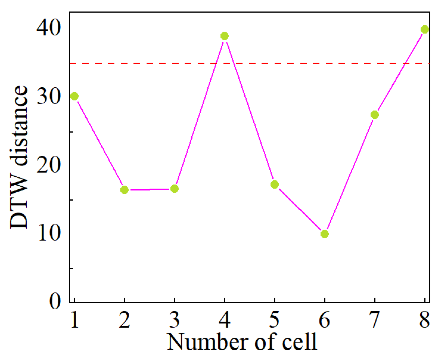
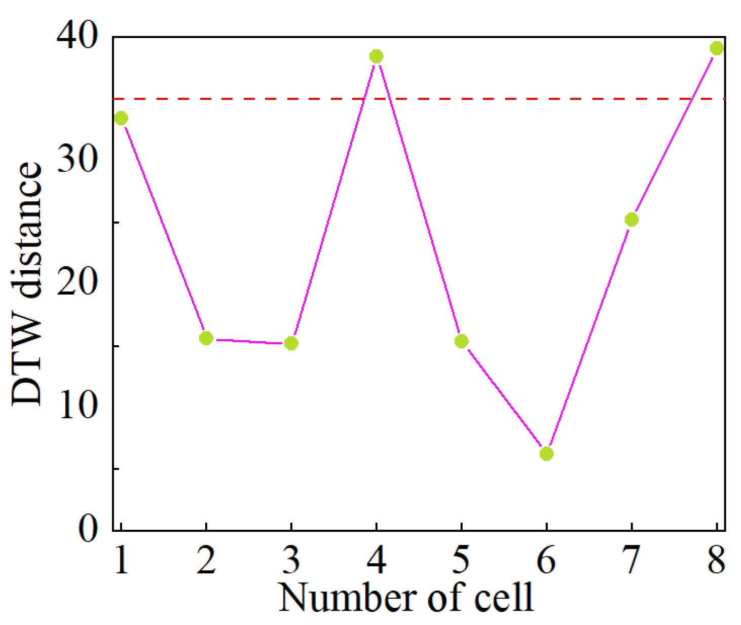
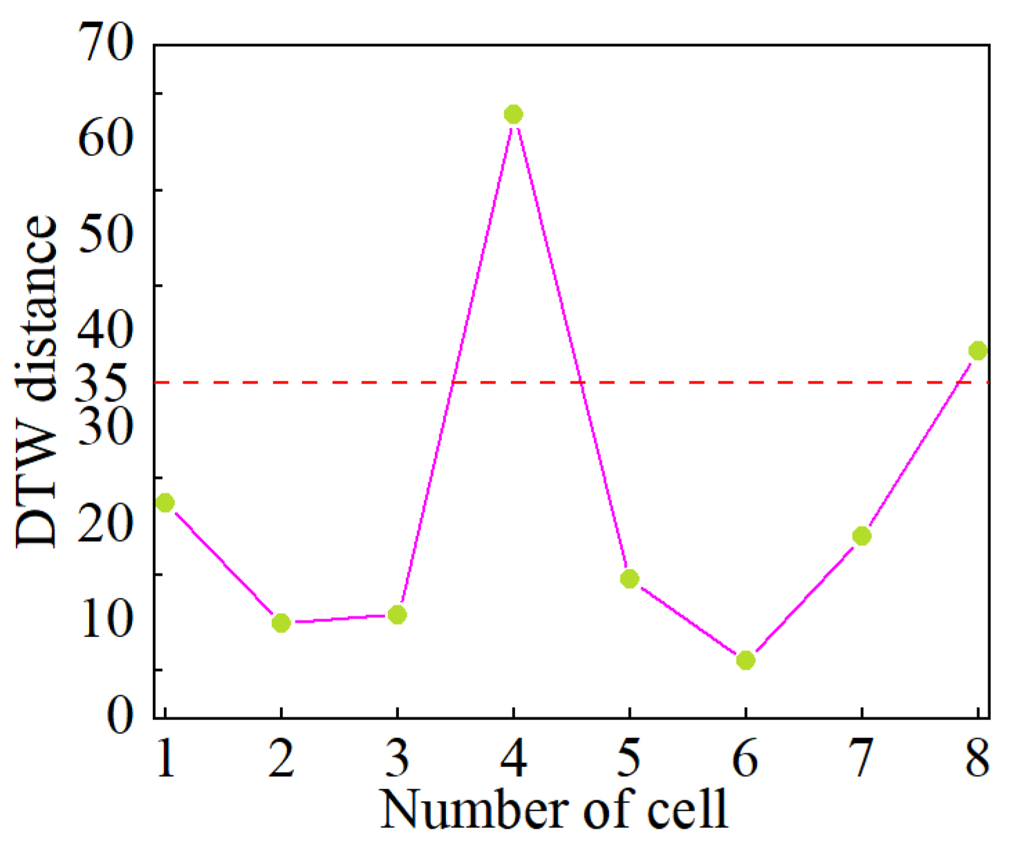
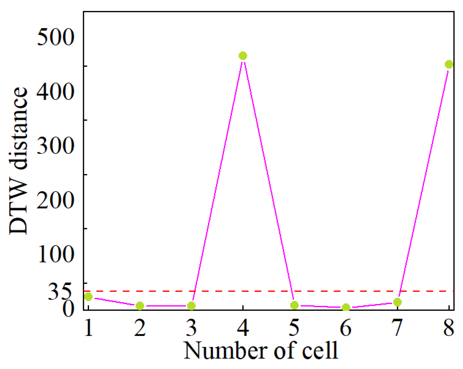
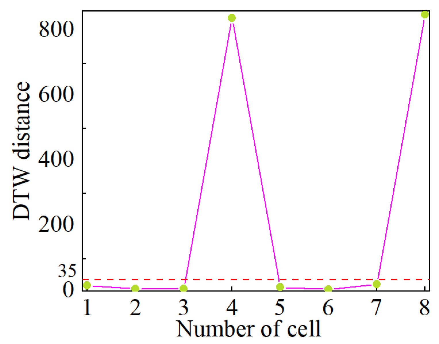
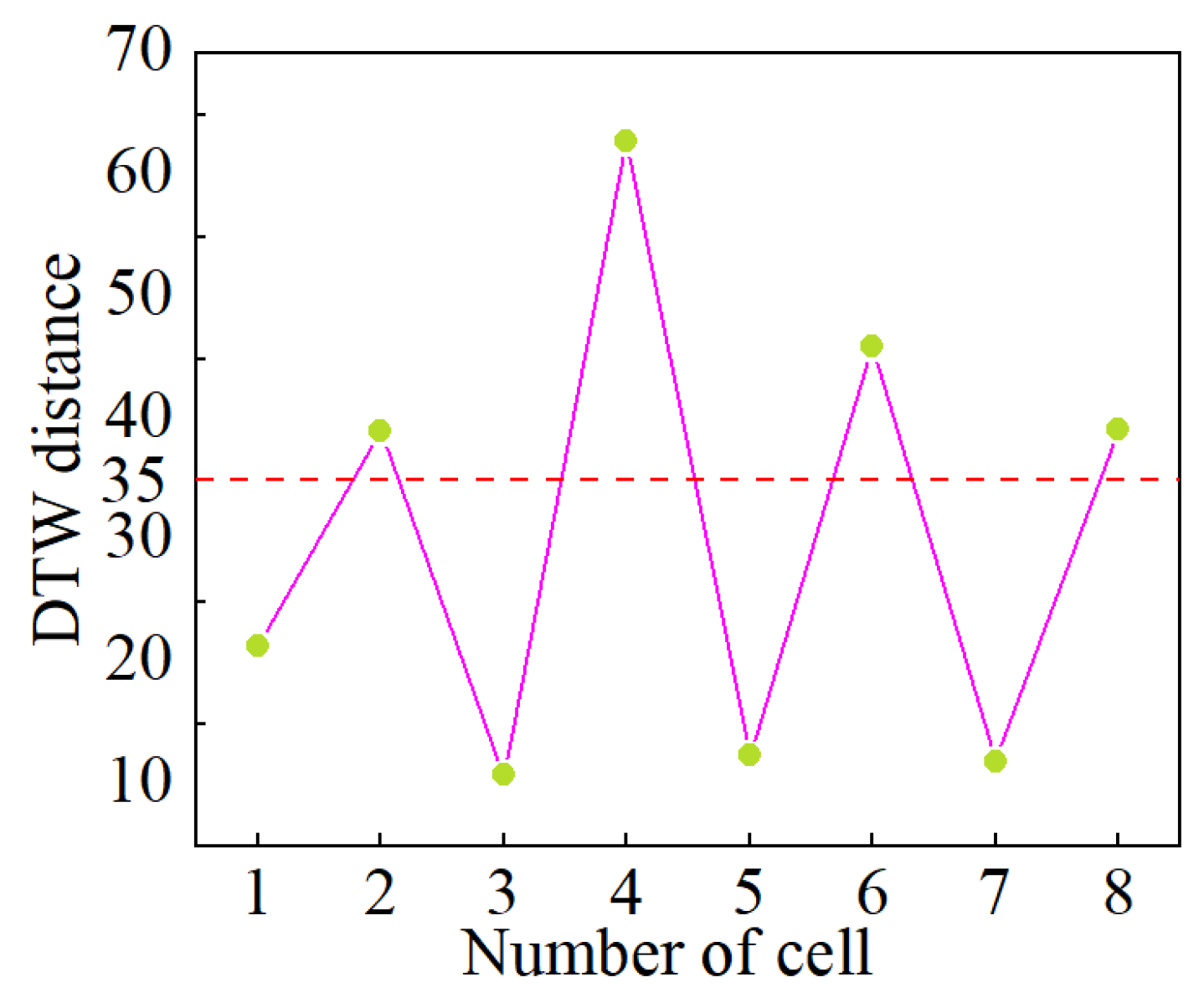
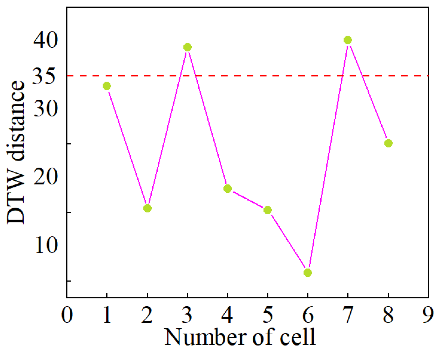
4.1. The Qualitative Detection Results

Using the terminal voltages of individual cells within the LIB pack, along with the pack current data collected in Section 3, the IC curves for each cell across various cycles were generated following the methodology outlined in Section 2.1 and subsequently smoothed using a moving average filter. These IC curves are presented in Figure 4, Figure 5, Figure 6, Figure 7, Figure 8, Figure 9, Figure 10 and Figure 11. In these figures, the curves for Cells 4 and 8 are colored green and cyan, respectively, while the median IC curve is shown in yellow, and the IC curves for the remaining cells are illustrated in gray. As demonstrated in Figure 4, Figure 5, Figure 6, Figure 7, Figure 8, Figure 9, Figure 10 and Figure 11, the normal cells’ ICs consistently overlap across all cycles. Notably, the median IC closely aligns with the IC curves of the normal cells in each cycle, indicating its reliability as a representation of the normal cells’ status within the LIB pack. Furthermore, starting from the third cycle, the IC curves for the MSC cells (Cells 4 and 8) begin to shift leftward compared to those of the other cells. Both the starting point and the peak position progressively move further left as the equivalent SR decreases. This shift occurs because the SR continually dissipates energy from the MSC cells during charging, leading to a slower increase in their voltage and SOC relative to the other cells. As the SR continues to decline and SC increases, this effect becomes more pronounced. Similar trends can also be observed in the ICs of cells during the 4th, 6th, 8th, 10th, 12th, and 14th cycles; however, for the sake of brevity, these observations will not be reiterated in this paper.
Next, we calculate the DTW distance between the IC curve of each cell and the median IC curve, comparing these distances with a predetermined threshold to detect MSC cells. Specifically, the detection threshold is determined offline based on the DTW distance of the IC curves for individual cells during the first two fault-free cycles. Figure 12 and Figure 13 display the DTW distances of each cell in these cycles. As shown, the DTW distances of all cells remain below 35 in the fault-free condition. Therefore, to ensure diagnostic accuracy, the fault detection threshold is set to 35. It is important to note that in practical applications, the fault detection threshold can be flexibly adjusted based on the battery type, application scenario, and other factors to enhance the sensitivity of the fault detection algorithm.
The DTW distances of the cells within the LIB pack across different charge–discharge cycles are shown in Figure 14, Figure 15, Figure 16, Figure 17, Figure 18 and Figure 19, with the pink dashed line indicating the threshold. As observed from Figure 14, Figure 15, Figure 16, Figure 17, Figure 18 and Figure 19, coming from the third cycle, the DTW distances for cells 4 and 8 exceed the threshold, while the DTW distances for the other cells remain below the threshold, indicating that MSCs occurred in cells 4 and 8 from the third cycle onward, while the other cells remained normal. Furthermore, it is noted that as the short-circuit resistance decreases, the DTW distances for cells 4 and 8 show an increasing trend, indicating that the DTW distance of the MSC cells grows as the MSC worsens. These diagnostic results are consistent with the fault injection scenarios described in Section 3, demonstrating that the proposed method accurately detects MSC cells within the LIB pack and validating the effectiveness of the proposed method. Observations from the fault detection results of the 4th, 6th, 8th, 10th, 12th, and 14th charge–discharge cycles support the same conclusion, which will not be elaborated further for brevity.

4.2. The Estimated Results of SR

After identifying the MSC cells in the LIB pack, we proceeded to estimate their SRs using the methodology outlined in Section 2.3. The estimated results of the SRs for MSC cells are compiled in Table 3. According to Table 3, the maximum relative error in the estimated SR for MSC cell 4 is 3.85%, while for MSC cell 8, it reaches 4.26%. Furthermore, the table indicates that as the actual SR diminishes, the relative error in the estimated values also decreases. This observed trend can be explained by the fact that a reduction in SR leads to an increase in SC. The inaccuracies for the SRs stay within a tolerable range, highlighting the effectiveness of the proposed approach in quantifying MSCs.

4.3. Comparison with Existing Methods

To further emphasize the advantages of the proposed method, we will perform both qualitative and quantitative comparisons between our approach and two mainstream methods based on IC curves from existing research. The method proposed in this work adopts a distinctly different technical route from existing methods, fundamentally representing a data-driven strategy. Therefore, we compared our method with the IC curve-based methods presented in references [30,31] based on three criteria: the ability to detect MSCs, the capacity to quantitatively estimate SR, and the necessity of establishing a battery model. The comparative results are summarized in the Table 4 below.
As shown in the table, the method based on IC differences presented in reference [30] (denoted as the ICD method) is unable to detect MSCs within LIB packs in advance. Instead, it requires the calculation of SR for each individual cell, using the resistance values to identify which cells are in an MSC state. However, in a LIB pack composed of hundreds or thousands of cells, the number of cells experiencing simultaneous MSCs constitutes only a small fraction of the total. Consequently, this indiscriminate one-by-one calculation approach results in excessive and redundant computations, thereby escalating the load. In reference [31], the method based on IC curves and ECMs (denoted as the IC-ECM method) necessitates the establishment of an accurate ECM for estimating SR. However, the ECM of LIBs often fails to adequately reflect the true state of the cells. The precision of its predictions is significantly affected by model parameters, causing the estimation of SR to be limited by the accuracy of the model and vulnerable to fluctuations in parameter values.
In comparison to current methodologies, the benefits of the approach are as follows:
(1)
It enables the diagnosis of MSC in LIB packs without requiring the development of a precise battery model, thus circumventing the complications related to model accuracy.
(2)
The technique allows for simultaneous detection of MSCs and assessment of SR. This method of sequential detection followed by quantitative analysis is highly focused.
In terms of SR estimation, the results obtained from the two other methods are presented in Table 5. A comparison of Table 3 and Table 5 reveals that, for both Cell 4 and Cell 8, the relative error in the SR estimates produced by the proposed method is the smallest.

4.4. Further Discussion

4.4.1. Effects of Aging

As illustrated in Figure 1, essentially, this method detects MSCs by horizontally comparing the IC curves of different cells. In practical applications, lithium-ion cells undergo stringent screening before being assembled into a battery pack to ensure capacity consistency across cells as much as possible. During operation, lithium-ion battery systems are typically equipped with balancing systems to strictly control capacity differences within a reasonable range. In other words, in real-world use, the aging states of the cells within a pack generally remain well-aligned. Under these conditions, battery aging does not affect the effectiveness of the proposed method.
In certain exceptional cases, such as when the balancing system fails, significant discrepancies in the aging states of individual cells within the battery pack may arise. In such scenarios, both aged cells and MSC cells may coexist in the pack. Cell aging can also lead to changes in the IC curve. It is important to note, however, that the mechanisms by which aging and MSCs affect the IC curve of lithium-ion batteries are fundamentally different. Specifically, when an MSC occurs, the additional charge consumption caused by the SR requires more charging capacity to achieve the same voltage increase during charging. As a result, the IC value of the battery increases, as shown in Equation (1). In other words, compared to a healthy cell, the IC value of an MSC cell becomes larger, which in turn causes the IC curve of the MSC cell to shift upward relative to that of a normal cell.
In contrast to MSCs, aging results in a decrease in the IC value of the cells, leading to a downward shift of the IC curve for aged cells relative to that of healthy cells. In summary, MSCs cause the IC curve of the battery to shift upward and to the left, whereas aging results in a downward and rightward shift of the IC curve. This phenomenon has been observed and validated in [31]. Therefore, in practical applications, distinguishing between MSC cells and aged cells can be achieved by analyzing the peak values or overall shifts of the IC curves.
Based on the experimental platform outlined in Section 3, we conducted an additional set of experiments to validate the aforementioned conclusions using a battery pack containing both aged and MSC cells. Specifically, the battery pack consists of eight cells connected in series, with the specifications of the cells detailed in Table 1. The cells are numbered from Cell 1 to Cell 8, where Cell 2 and Cell 6 are aged cells with state of health (SOH) values of 95% and 90%, respectively. Cell 4 and Cell 8 are MSC cells, with a SR of 100 Ω. The initial SOH values of the individual cells before the experiments are presented in Table 6.
At this point, the IC curves and DTW distances for each cell are obtained, as shown in Figure 20 and Figure 21. It is observed that the IC curves of Cells 1, 3, 5, and 7 coincide, and their DTW distances are below the threshold, indicating that these cells are diagnosed as normal. In contrast, the DTW distances for Cells 2, 4, 6, and 8 exceed the threshold, and their IC curves exhibit distinct trends. Specifically, the IC curves of Cells 2 and 6 shift downward to the right compared to those of the normal cells, while the IC curves of Cells 4 and 8 shift upward to the left. Consequently, Cells 2 and 6 are identified as aging cells, whereas Cells 4 and 8 are categorized as MSC cells. These results suggest that when the equalization system fails and both aging cells and MSC cells coexist within the battery pack, the differentiation between these two types of cells can be achieved by analyzing the varying trends of their IC curves.

4.4.2. Effects of Temperature and Initial SOC on SR

Based on existing studies on ISC faults in lithium-ion batteries, the relationship between equivalent SR and temperature is shown in Figure 22 [32]. It can be observed that as the SR decreases, the severity of the short circuit increases, leading to a gradual rise in temperature. This suggests that the higher the temperature, the more severe the short circuit, and the lower the SR.
Figure 23 illustrates the voltage and temperature variation curves of a lithium-ion battery when an internal short-circuit fault is triggered at different initial SOCs [33]. It is observed that a higher initial SOC results in more drastic changes in voltage and temperature during an internal short circuit event. Additionally, the variations in voltage and temperature are directly correlated with the magnitude of the short circuit resistance. Thus, it can be inferred that a higher initial SOC corresponds to a lower SR, leading to a more severe short circuit condition.
Due to constraints in experimental costs and time, this study only validates the proposed method under ambient temperature conditions and with good consistency in the initial SOC among the individual cells. We will comprehensively validating the effectiveness and accuracy of the proposed method across varying temperatures and initial SOC levels in future.

4.4.3. Impact of Cell Order Rearrangement

The median terminal voltage and median IC curve are unaffected by the arrangement of the battery cells, and therefore, changing the cell order has no impact on the diagnostic results. In this subsection, we validate this conclusion by adding an additional set of experiments.
Specifically, the battery pack used for validation is the same as that employed in the experiments described in Section 3. We reversed the connection order of the cells in the original battery pack; for instance, Cell 8 was moved to Position 1, Cell 7 to Position 2, and so forth. Subsequently, a 200 Ω SR was connected in parallel across the terminals of Cells 3 and 7 in the rearranged battery pack, while the other cells operated normally.
At this point, the IC curves and DTW distances of each cell in the battery pack are presented in Figure 24 and Figure 25, respectively. It can be observed that the IC curves of Cells 1, 2, 4, 5, 6, and 8 closely align with the median IC curve, and their DTW distances are all below the threshold, leading to their diagnosis as normal cells. In contrast, the IC curves of Cells 3 and 7 are shifted upwards and to the left compared to the normal cells, with their DTW distances exceeding the threshold, resulting in their classification as MSC cells. These diagnostic results are consistent with those observed in Figure 7 and Figure 15, further confirming that altering the order of the cells does not affect the diagnostic outcomes of the proposed method.

5. Conclusions

This paper introduces a method for detecting and quantitatively evaluating MSC faults in energy storage LIB packs, utilizing IC analysis alongside DTW algorithms. The median IC curve, derived from the sorted terminal voltages of the cells in the LIB pack, serves as a reference point to define the condition of normal cells within the pack. The DTW algorithm quantitatively assesses the similarity between the IC curve of each cell and the median IC curve, facilitating the identification of MSC cells. For the identified MSC cells, the SR is estimated based on variations in charging voltage. The outcomes of fault detection and quantitative evaluation indicate that the median IC curve consistently corresponds with the IC curves of normal cells, effectively representing their condition within the LIB pack. The highest relative error in the SR estimation recorded is 4.26%. Since the proposed approach does not necessitate the development of a battery model and employs a detection-first, quantification-later strategy, it enhances both applicability and computational efficiency. Future research will aim to validate the effectiveness and practicality of this method across various battery material systems and under different environmental temperatures.
It should be noted that the current version of the proposed method requires a complete IC curve. In electric vehicle applications, the initial SOC may not be 0% due to variations in user charging habits, making it impossible to obtain a full IC curve in such cases. A potential solution to this issue is to extract key features from the IC curve, such as peak values, peak positions, and peak areas, to form a feature vector that can be used for fault detection in place of the complete IC curve. This will be a primary focus of our future research. Moreover, since temperature and initial SOC influence the shape and trend of IC curves, they also affect the selection of the threshold. In practical applications, extensive offline testing under different temperature and initial SOC conditions can be conducted to determine a threshold that is robust to these variations, ensuring diagnostic accuracy. This will be another key focus of our future work.

Author Contributions

M.Z.: Conceptualization, Methodology, Writing—original draft. Q.G.: Writing—review & editing. K.F.: Software. X.D.: Validation. H.Z.: Visualization. Q.Z.: Investigation. Q.Y.: Formal analysis. C.L.: Supervision. All authors have read and agreed to the published version of the manuscript.

Funding

This research was funded by the project from State Grid Shanxi Electric Power Company grant number [520530240027].

Data Availability Statement

The authors do not have permission to share data.

Conflicts of Interest

Author Meng Zhang, Qiang Guo, Ke Fu, Xiaogang Du, Hao Zhang, Qi Zuo, Qi Yang and Chao Lyu were employed by the State Grid Shanxi Electric Power Company. The remaining author declare that the research was conducted in the absence of any commercial or financial relationships that could be construed as a potential conflict of interest.

References

  1. Degen, F.; Winter, M.; Bendig, D.; Tübke, J. Energy consumption of current and future production of lithium-ion and post lithium-ion battery cells. Nat. Energy 2023, 8, 1284–1295. [Google Scholar] [CrossRef]
  2. Kim, N.; Kim, Y.; Sung, J.; Cho, J. Issues impeding the commercialization of laboratory innovations for energy-dense Si-containing lithium-ion batteries. Nat. Energy 2023, 8, 921–933. [Google Scholar] [CrossRef]
  3. Tian, J.; Fan, Y.; Pan, T.; Zhang, X.; Yin, J.; Zhang, Q. A critical review on inconsistency mechanism, evaluation methods and improvement measures for lithium-ion battery energy storage systems. Renew. Sustain. Energy Rev. 2024, 189, 113978. [Google Scholar] [CrossRef]
  4. Sun, C.; Lu, T.; Li, Q.; Liu, Y.; Yang, W.; Xie, J. Predicting the Future Capacity and Remaining Useful Life of Lithium-Ion Batteries Based on Deep Transfer Learning. Batteries 2024, 10, 303. [Google Scholar] [CrossRef]
  5. Peng, S.; Zhu, J.; Wu, T.; Tang, A.; Kan, J.; Pecht, M. SOH early prediction of Lithium-ion batteries based on voltage interval selection and features fusion. Energy 2024, 308, 132993. [Google Scholar] [CrossRef]
  6. Shen, D.; Lyu, C.; Yang, D.; Hinds, G.; Ma, K.; Xu, S.; Bai, M. Concurrent multi-fault diagnosis of lithium-ion battery packs using random convolution kernel transformation and Gaussian process classifier. Energy 2024, 306, 132467. [Google Scholar] [CrossRef]
  7. Mehta, C.; Sant, A.V.; Sharma, P. Optimized ANN for LiFePO4 Battery Charge Estimation using Principal Components based Feature Generation. Green Energy Intell. Transp. 2024, 3, 100175. [Google Scholar] [CrossRef]
  8. Shen, D.; Yang, D.; Lyu, C.; Ma, J.; Hinds, G.; Sun, Q.; Du, L.; Wang, L. Multi-sensor multi-mode fault diagnosis for lithium-ion battery packs with time series and discriminative features. Energy 2024, 290, 130151. [Google Scholar] [CrossRef]
  9. Cai, H.; Tang, X.; Lai, X.; Wang, Y.; Han, X.; Ouyang, M.; Zheng, Y. How battery capacities are correctly estimated considering latent short-circuit faults. Appl. Energy 2024, 375, 124190. [Google Scholar] [CrossRef]
  10. Li, S.; Zhang, C.; Du, J.; Cong, X.; Zhang, L.; Jiang, Y.; Wang, L. Fault diagnosis for lithium-ion batteries in electric vehicles based on signal decomposition and two-dimensional feature clustering. Green Energy Intell. Transp. 2022, 1, 100009. [Google Scholar] [CrossRef]
  11. Shen, D.; Lyu, C.; Yang, D.; Hinds, G.; Wang, L. Connection fault diagnosis for lithium-ion battery packs in electric vehicles based on mechanical vibration signals and broad belief network. Energy 2023, 274, 127291. [Google Scholar] [CrossRef]
  12. Shen, D.; Wu, L.; Kang, G.; Guan, Y.; Peng, Z. A novel online method for predicting the remaining useful life of lithium-ion batteries considering random variable discharge current. Energy 2021, 218, 119490. [Google Scholar] [CrossRef]
  13. Wang, P.; Chen, J.; Lan, F.; Li, Y.; Feng, Y. Multiscale feature fusion approach to early fault diagnosis in EV power battery using operational data. J. Energy Storage 2024, 98, 112812. [Google Scholar] [CrossRef]
  14. Zou, B.; Zhang, L.; Xue, X.; Tan, R.; Jiang, P.; Ma, B.; Song, Z.; Hua, W. A review on the fault and defect diagnosis of lithium-ion battery for electric vehicles. Energies 2023, 16, 5507. [Google Scholar] [CrossRef]
  15. Zhang, J.; Wang, Y.; Jiang, B.; He, H.; Huang, S.; Wang, C.; Zhang, Y.; Han, X.; Guo, D.; He, G.; et al. Realistic fault detection of li-ion battery via dynamical deep learning. Nat. Commun. 2023, 14, 5940. [Google Scholar] [CrossRef]
  16. Yuan, H.; Cui, N.; Li, C.; Cui, Z.; Chang, L. Early stage internal short circuit fault diagnosis for lithium-ion batteries based on local-outlier detection. J. Energy Storage 2023, 57, 106196. [Google Scholar] [CrossRef]
  17. Zhang, Y.; Jiang, M.; Zhou, Y.; Zhao, S.; Yuan, Y. Towards high-safety lithium-ion battery diagnosis methods. Batteries 2023, 9, 63. [Google Scholar] [CrossRef]
  18. Khaneghah, M.Z.; Alzayed, M.; Chaoui, H. Fault detection and diagnosis of the electric motor drive and battery system of electric vehicles. Machines 2023, 11, 713. [Google Scholar] [CrossRef]
  19. Wu, M.; Sun, M.; Zhang, F.; Wang, L.; Zhao, N.; Wang, J.; Huang, W. A fault detection method of electric vehicle battery through Hausdorff distance and modified Z-score for real-world data. J. Energy Storage 2023, 60, 106561. [Google Scholar] [CrossRef]
  20. Waseem, M.; Ahmad, M.; Parveen, A.; Suhaib, M. Battery technologies and functionality of battery management system for EVs: Current status, key challenges, and future prospectives. J. Power Sources 2023, 580, 233349. [Google Scholar] [CrossRef]
  21. Lai, X.; Yi, W.; Kong, X.; Han, X.; Zhou, L.; Sun, T.; Zheng, Y. Online detection of early stage internal short circuits in series-connected lithium-ion battery packs based on state-of-charge correlation. J. Energy Storage 2020, 30, 101514. [Google Scholar] [CrossRef]
  22. Chang, C.; Zhou, X.; Jiang, J.; Gao, Y.; Jiang, Y.; Wu, T. Electric vehicle battery pack micro-short circuit fault diagnosis based on charging voltage ranking evolution. J. Power Sources 2022, 542, 231733. [Google Scholar] [CrossRef]
  23. Zheng, Y.; Lu, Y.; Gao, W.; Han, X.; Feng, X.; Ouyang, M. Micro-short-circuit cell fault identification method for lithium-ion battery packs based on mutual information. IEEE Trans. Ind. Electron. 2020, 68, 4373–4381. [Google Scholar] [CrossRef]
  24. Ma, M.; Duan, Q.; Li, X.; Liu, J.; Zhao, C.; Sun, J.; Wang, Q. Fault diagnosis of external soft-short circuit for series connected lithium-ion battery pack based on modified dual extended Kalman filter. J. Energy Storage 2021, 41, 102902. [Google Scholar] [CrossRef]
  25. Kong, X.; Zheng, Y.; Ouyang, M.; Lu, L.; Li, J.; Zhang, Z. Fault diagnosis and quantitative analysis of micro-short circuits for lithium-ion batteries in battery packs. J. Power Sources 2018, 395, 358–368. [Google Scholar] [CrossRef]
  26. Xu, Y.; Ge, X.; Shen, W.; Yang, R. A soft short-circuit diagnosis method for lithium-ion battery packs in electric vehicles. IEEE Trans. Power Electron. 2022, 37, 8572–8581. [Google Scholar] [CrossRef]
  27. Shen, D.; Yang, D.; Lyu, C.; Hinds, G.; Wang, L.; Bai, M. Detection and quantitative diagnosis of micro-short-circuit faults in lithium-ion battery packs considering cell inconsistency. Green Energy Intell. Transp. 2023, 2, 100109. [Google Scholar] [CrossRef]
  28. Lei, D.; Zhang, M.; Guo, Q.; Gao, Y.; Bai, Z.; Yang, Q.; Fu, K.; Lyu, C. Model-free detection and quantitative assessment of micro short circuits in lithium-ion battery packs based on incremental capacity and unsupervised clustering. Int. J. Electrochem. Sci. 2024, 19, 100794. [Google Scholar] [CrossRef]
  29. Yadav, M.; Alam, M.A. Dynamic time warping (dtw) algorithm in speech: A review. Int. J. Res. Electron. Comput. Eng. 2018, 6, 524–528. [Google Scholar]
  30. Qiao, D.; Wang, X.; Lai, X.; Zheng, Y.; Wei, X.; Dai, H. Online quantitative diagnosis of internal short circuit for lithium-ion batteries using incremental capacity method. Energy 2022, 243, 123082. [Google Scholar] [CrossRef]
  31. Sun, J.; Chen, S.; Xing, S.; Guo, Y.; Wang, S.; Wang, R.; Wu, Y.; Wu, X. A battery internal short circuit fault diagnosis method based on incremental capacity curves. J. Power Sources 2024, 602, 234381. [Google Scholar] [CrossRef]
  32. Lai, X.; Jin, C.; Yi, W.; Han, X.; Feng, X.; Zheng, Y.; Ouyang, M. Mechanism, modeling, detection, and prevention of the internal short circuit in lithium-ion batteries: Recent advances and perspectives. Energy Storage Mater. 2021, 35, 470–499. [Google Scholar] [CrossRef]
  33. Huang, L.; Liu, L.; Lu, L.; Feng, X.; Han, X.; Li, W.; Zhang, M.; Li, D.; Liu, X.; Sauer, D.U. A review of the internal short circuit mechanism in lithium-ion batteries: Inducement, detection and prevention. Int. J. Energy Res. 2021, 45, 15797–15831. [Google Scholar] [CrossRef]
Figure 1. The general structure of the method being proposed.
Batteries 10 00378 g001
Figure 2. Schematic diagram of the SC estimation principle based on changes in MCV. The green dashed line here represents the remaining charging segment, and the green solid line with arrows at both ends represents the remaining charging time.
Batteries 10 00378 g002
Figure 3. Experimental platform.
Batteries 10 00378 g003
Figure 4. IC curves in Cycle 1 without MSCs.
Batteries 10 00378 g004
Figure 5. IC curves in Cycle 2 without MSCs.
Batteries 10 00378 g005
Figure 6. IC curves in Cycle 3 with a SR of 300 Ω.
Batteries 10 00378 g006
Figure 7. IC curves in Cycle 5 with a SR of 200 Ω.
Batteries 10 00378 g007
Figure 8. IC curves in Cycle 7 with a SR of 100 Ω.
Batteries 10 00378 g008
Figure 9. IC curves in Cycle 9 with a SR 50 Ω.
Batteries 10 00378 g009
Figure 10. IC curves in Cycle 11 with a SR of 10 Ω.
Batteries 10 00378 g010
Figure 11. IC curves in Cycle 13 with a SR of 5 Ω.
Batteries 10 00378 g011
Figure 12. DTW distances of each cell in Cycle 1 when no MSCs occurred. The red dashed line here represents the threshold. The green dots represent the DTW distance of each individual cell, and the pink lines connect them together.
Batteries 10 00378 g012
Figure 13. DTW distances of each cell in Cycle 2 when no MSCs occurred. The red dashed line here represents the threshold. The green dots represent the DTW distance of each individual cell, and the pink lines connect them together.
Batteries 10 00378 g013
Figure 14. DTW distances of each cell in Cycle 3 with a SR of 300 Ω. The red dashed line here represents the threshold. The green dots represent the DTW distance of each individual cell, and the pink lines connect them together.
Batteries 10 00378 g014
Figure 15. DTW distances of each cell in Cycle 5 with a SR of 200 Ω. The red dashed line here represents the threshold. The green dots represent the DTW distance of each individual cell, and the pink lines connect them together.
Batteries 10 00378 g015
Figure 16. DTW distances of each cell in Cycle 7 with a SR of 100 Ω. The red dashed line here represents the threshold. The green dots represent the DTW distance of each individual cell, and the pink lines connect them together.
Batteries 10 00378 g016
Figure 17. DTW distances of each cell in Cycle 9 with a SR of 50 Ω. The red dashed line here represents the threshold. The green dots represent the DTW distance of each individual cell, and the pink lines connect them together.
Batteries 10 00378 g017
Figure 18. DTW distances of each cell in Cycle 11 with a SR of 10 Ω. The red dashed line here represents the threshold. The green dots represent the DTW distance of each individual cell, and the pink lines connect them together.
Batteries 10 00378 g018
Figure 19. DTW distances of each cell in Cycle 13 with a SR of 5 Ω. The red dashed line here represents the threshold. The green dots represent the DTW distance of each individual cell, and the pink lines connect them together.
Batteries 10 00378 g019
Figure 20. IC curves of each cell in the battery pack containing both aging cells and MSC cells.
Batteries 10 00378 g020
Figure 21. DTW distances corresponding to each cells in the battery pack containing both aging cells and MSC cells. The red dashed line here represents the threshold. The green dots represent the DTW distance of each individual cell, and the pink lines connect them together.
Batteries 10 00378 g021
Figure 22. Schematic diagram of the relationship between ISC resistance and temperature [32]. The red line here represents the temperature change curve, and the green area represents the region before reaching the T2 temperature value. The blue dashed line represents the T2 temperature value.
Batteries 10 00378 g022
Figure 23. Voltage and temperature variation curves of lithium-ion batteries when triggering an internal short-circuit fault at different initial SOCs [33], (A) Voltage versus time curve; (B) Temperature versus time curve.
Batteries 10 00378 g023
Figure 24. IC curves of individual cells in the battery pack after rearranging the cell order.
Batteries 10 00378 g024
Figure 25. DTW distances of individual cells in the battery pack after rearranging the cell order. The red dashed line here represents the threshold. The green dots represent the DTW distance of each individual cell, and the pink lines connect them together.
Batteries 10 00378 g025
Table 1. Relevant parameters of the battery cell.
ParameterValue
CathodeLiNi0.5Co0.2Mn0.3O2
AnodeGraphite
Rated capacity4.20 Ah
Operating temperature−20~+60 °C
Rated voltage3.65 V
Charging cut-off voltage4.20 V
Discharging cut-off voltage2.75 V
Table 2. SRs for different cycles.
CyclesThe SR for Cell 4The SR for Cell 8
1–2
3, 4300 Ω300 Ω
5, 6200 Ω200 Ω
7, 8100 Ω100 Ω
9, 1050 Ω50 Ω
11, 1210 Ω10 Ω
13, 145 Ω5 Ω
Table 3. Estimation results of SRs.
Cells Cycles
3–45–67–89–1011–1213–14
4True SRs (Ω)30020010050105
Estimated SRs (Ω)311.54206.46103.1151.3710.175.06
Relative Error (%)3.853.233.112.741.701.20
8True SRs (Ω)30020010050105
Estimated SRs (Ω)312.77207.34103.5751.3110.245.09
Relative Error (%)4.263.673.572.622.401.80
Table 4. Qualitative comparison.
MethodsQualitative DetectionQuantitative EstimationModel-Free
IC difference [30]×
IC + ECM [31]×
The proposed method
Table 5. SR estimation results from the three methodologies.
CellTrue SRs (Ω)ICD Method [30]IC-ECM Method [31]
Estimated SRs (Ω)Relative Error (%)Estimated SRs (Ω)Relative Error (%)
4300323.117.70328.859.62
200185.427.29216.348.17
10090.749.26104.124.12
5056.7813.5648.053.90
108.7512.509.782.20
55.265.204.882.40
8300325.318.44328.999.66
200184.347.83215.657.83
10088.3711.63104.374.37
5058.1116.2252.014.02
108.9710.3010.363.60
55.285.604.862.80
Table 6. Initial SOH of each cell prior to the aging validation experiment.
Cell Number12345678
Initial SOH (%)1009510010010090100100
Disclaimer/Publisher’s Note: The statements, opinions and data contained in all publications are solely those of the individual author(s) and contributor(s) and not of MDPI and/or the editor(s). MDPI and/or the editor(s) disclaim responsibility for any injury to people or property resulting from any ideas, methods, instructions or products referred to in the content.

