Abstract
The control of energy storage systems (ESSs) within autonomous microgrids (MGs) is critical for ensuring stable and efficient operation, especially when incorporating renewable energy resources (RESs) such as photovoltaic (PV) systems. This paper addresses managing a standalone DC microgrid that combines PV generation and a battery energy storage system (BESS). We propose a hybrid control strategy that combines a Recurrent Neural Network (RNN) with Proportional-Integral (PI) controllers to improve the performance of the bidirectional converter that connects the BESS to the microgrid. The RNN processes the voltage error and derivative into a reference current, which a PI controller refines to determine the best duty cycle for the converter’s switches. This hybrid control scheme provides superior adaptability and performance in various load conditions, including pulsed power load (PPL) demands. Simulation results show that the proposed control method exceeds traditional PI-PI control algorithms, particularly in improving the transient stability of the DC bus voltage and optimizing BESS performance. We conducted extensive hardware experiments to verify the robustness and effectiveness of the developed control algorithm. The experimental results confirmed the superior performance of the hybrid RNN-PI control scheme, demonstrating its ability to maintain system stability and efficiency across a wide range of real-world scenarios. This experimental validation reflects the reliability and effectiveness of the proposed control strategy in improving microgrid operations.
1. Introduction
As the energy sector advances toward sustainability, microgrids have emerged as critical components in transitioning away from conventional power systems [1]. Historically, reliance on fossil fuels has contributed significantly to global warming and the depletion of limited resources [2]. These environmental concerns have accelerated the adoption of renewable energy sources (RESs), which provide a more efficient and sustainable alternative. Microgrids are notable for their ability to efficiently incorporate a variety of distributed energy resources (DERs), including photovoltaic (PV) systems, wind turbines, and energy storage systems, which store energy in direct current [3,4,5].
DC microgrids have several advantages over standard alternating current (AC) systems, including simplified control techniques that minimize harmonics and improve power distribution efficiency. Despite these advantages, incorporating RESs into microgrids poses significant challenges, given their intermittent nature. To maintain consistent and reliable operation in the face of such variability, advanced energy storage systems (ESSs) must be used. The fluctuating output of RES-based generation, impacted by meteorological conditions, can produce instability when load demands change. To address these concerns, precise voltage regulation and robust control systems are critical for ensuring system stability and preventing issues like load shedding [6,7].
Traditional control techniques in DC microgrids primarily focus on voltage regulation to manage power flow. These methods range from simple Proportional-Integral (PI) controllers to more complex algorithms designed to maintain stability. Conventional controllers can manage the DC voltage regulation in normal operating conditions; however, under severe scenarios and unpredictable changes, these controllers cannot perform well due to the linear nature of these controllers, which often needs to be improved for handling the non-linear dynamics of microgrids [8]. The emergence of artificial intelligence (AI) and data-driven control systems has brought a new level of sophistication to microgrid management. Machine learning (ML) techniques, including supervised learning for load forecasting, unsupervised learning for pattern recognition, and reinforcement learning for dynamic energy management, are revolutionizing how microgrids adapt to changing conditions. These techniques enable real-time optimization, fault detection, and predictive analytics, ensuring energy resources’ efficiency. Despite these advancements, DC microgrids must often manage stability challenges posed by specific types of loads, such as pulse power loads (PPLs). PPLs are characterized by their disposition to draw large amounts of power quickly. These rapid energy discharges can lead to significant voltage drops that have the potential to destabilize the microgrid [9,10,11,12]. Although Proportional-Integral (PI) controllers have been widely used for voltage regulation and stabilization in DC microgrids, their linear nature limits their effectiveness in handling the non-linear dynamics and complex operational scenarios that such loads introduce. Recent advancements suggest integrating adaptive control methods and AI techniques, such as Artificial Neural Networks (ANNs), which can significantly enhance system stability and performance, particularly in managing non-linearities, dynamic load changes, and transient disturbances. Their ability to learn and adapt quickly provides a robust solution for maintaining stability under various operational conditions, outperforming traditional PI controllers in many scenarios [7].
Several studies have shown how this hybrid control strategy can overcome the current setbacks and enhance performance. In [13], the authors investigated neural networks for power system stability with high accuracy. The new voltage stability pointer (NVSP) technique effectively predicts voltage instability in power systems. Both feedforward neural network (FFNN) and cascade-forward neural network (CFNN) control methodologies are employed, as well as Layer recurrent neural network (LRNN) and linear layer neural network (LLNN). The system is tested on IEEE 30-bus and Nigerian power systems through MATLAB simulation. The results show safe power ranges for IEEE 30-bus and Nigerian power systems. Moreover, FFNN and CFNN perform better in terms of accuracy and efficiency. From the performance point of view, FFNN ranked first, and CFNN second for IEEE 30-bus system accuracy. Meanwhile, CFNN showed superior performance to FFNN regarding NGP system predictability.
Data-driven models using neural networks for dynamic system prediction accuracy are investigated in [14]. A two-coefficient loss function is employed, and prediction accuracy is enhanced in substructure modeling. The authors have also implemented adjustable learning rates and control parameters for improved performance. The paper concluded that training data selection and the hidden layer number impact prediction ability significantly. Furthermore, the simulation results showed that the substructure data-driven modeling has higher prediction accuracy than the whole modeling and that the adjustable learning rate and control parameters enhance network performance.
The authors in [15] reviewed ANN-based optimization techniques for enhanced AI performance and focused on manipulating parameters for optimal neural network structure through managing time in selecting parameters and training neural networks. They provided examples of ANN improvement using hybrid optimization techniques. The authors have also compared ANN along with Particle Swarm Optimization (PSO), Genetic Algorithm (GA), Artificial Bee Colony (ABC), and Backtracking Search Algorithm (BSA) using MATLAB/SIMULINK.
An ANN-Model Predictive Control (MPC) for DC microgrid stability with photovoltaic-battery systems is proposed in [16]. The ANN-MPC is employed for problem identification, voltage sag classifications, and short-term prediction. The authors compared ANN-MPC with conventional PI controllers for grid-connected DC microgrids, and the results showed that the hybrid ANN-MPC controller outperformed conventional PI controller as it achieves rapid power balancing and voltage damping under variable conditions as well as showing efficacy in reducing instability and oscillations in DC microgrids. The simulation and experimental results showed robustness, faster dynamics, lower oscillation, and better performance for the proposed controller.
In [17], the authors presented an ANN controller for interconnected microgrids’ frequency and power control. They proposed a decentralized Load Frequency Control (LFC) system for interconnected MGs with improved dynamic performance. They also utilized an ANN controller for frequency and tie-line power control in interconnected MGs. The validation is carried out through extensive simulation for two interconnected microgrids. Simulation results show that ANN controllers outperform conventional controllers, such as PI, in various conditions. Moreover, the ANN-based LFC system provides desirable dynamic responses in different situations.
In [18], the authors propose a maximum power point tracking approach using an artificial neural network with a PI controller for a boost converter. The paper also compares the performance of the ANN-based MPPT controller with the conventional Perturb and Observe (P&O) method. Simulations conducted using MATLAB software validate the effectiveness of the proposed ANN-based MPPT controller in optimizing PV system performance under varying environmental conditions.
In [19], a Hidden Layer Recurrent Neural Network (HLRNN) as a control method for a dual-fed induction generator in a wind power generation system is presented; authors conclude that HLRNN enhances adaptability by ensuring self-adaptation of the PI controller, particularly under severe conditions such as wind speed changes. Another perspective to show the importance of the hybrid method was introduced in [20], in which the authors introduce a novel Hybrid Energy Storage System (HESS) control strategy for integrating a PV generator with Fuzzy Logic Control (FLC), supercapacitors (SC), and lithium-ion batteries. Adding Sliding Mode (SM) and Artificial Neural Network (ANN) controllers enhances system robustness. MATLAB/Simulink simulations validate the strategy’s effectiveness in rapidly regulating DC bus voltage and ensuring continuous PV system operation with improved efficiency. Moreover, this paper [21] proposes a hybrid PI-NN controller for PV systems with batteries and supercapacitors, optimizing energy storage by utilizing PI for voltage control and Neural Network for improved sensitivity and responsiveness. The evaluation shows the controller’s potential to enhance PV system efficiency under challenging load conditions. In [22], the study investigates various hybrid Maximum Power Point Tracking (MPPT) controllers tailored for fuel cell-fed boost converter systems. Simulation results show that the hybrid controllers outperform others regarding tracking speed, stability near the Maximum Power Point (MPP), and adaptability to temperature fluctuations, highlighting their effectiveness in enhancing fuel cell power extraction.
The conclusion from the previous papers demonstrates that hybrid controllers such as PI and neural network control systems will combine their strengths, offering a more robust and adaptable solution for DC microgrids to handle complex operation scenarios. These hybrid systems leverage the simplicity and reliability of PI controllers for steady-state conditions while utilizing the adaptability and predictive capabilities of Neural Networks. This combination ensures precise voltage regulation and efficient energy distribution. By integrating these control strategies, hybrid PI and Neural Network systems provide a comprehensive approach to managing the complexities of DC microgrids, ensuring stable and resilient operation even under challenging conditions. The control strategies and key features of various neural network-based approaches in power systems, as summarized in Table 1.

Table 1.
Summary of hybrid Control Strategies and Their Key Features.
This study introduces a hybrid PI-NN (Proportional-Integral Neural Network) controller to mitigate the impact of pulsed loads on a standalone DC microgrid, which includes a PV system and battery energy storage. The proposed hybrid control scheme enhances the overall system stability by improving the DC microgrid voltage’s performance and the BESS-generated power’s dynamic performance during the charging/discharging process under various operating conditions. In this approach, a Recurrent Neural Network (RNN) regulates the outer voltage loop, effectively capturing dynamic system behaviors and generating precise current reference. A PI controller in the inner current loop then manages these references, ensuring that accurate, current regulation meets the immediate power demands and maintains system stability.
The study is organized as follows: Section 2 presents a comprehensive standalone DC microgrid modeling, while Section 3 investigates the complexities of the proposed hybrid PI-NN methodology. Section 4 and Section 5 present an in-depth examination of outcomes and discussions from experimental validations and simulations. Section 6 concludes with a concise summary of results and future work.
2. Microgrid System Architecture and Description
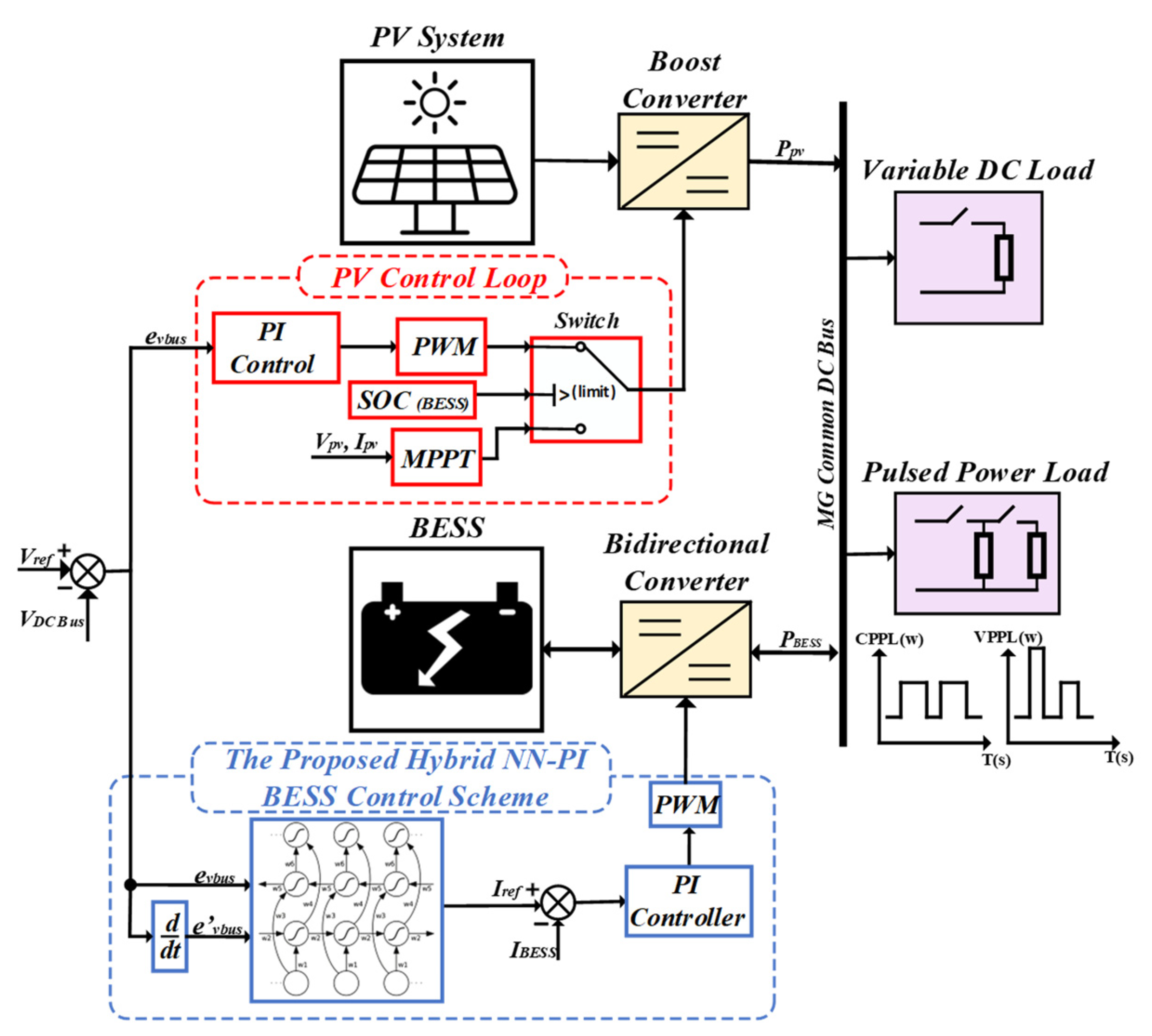
The microgrid system under consideration in Figure 1 comprises several key components working in synergy to provide a reliable and efficient power supply to local loads while enabling grid interaction. The core elements of this microgrid include a solar photovoltaic (PV) system, a battery energy storage system (BESS), and a local DC bus that interconnects these components.
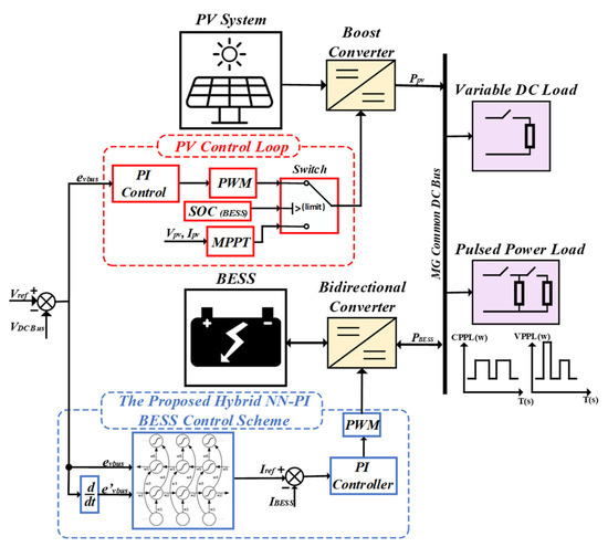
Figure 1.
Proposed standalone DC microgrid.
2.1. Photovoltaic System
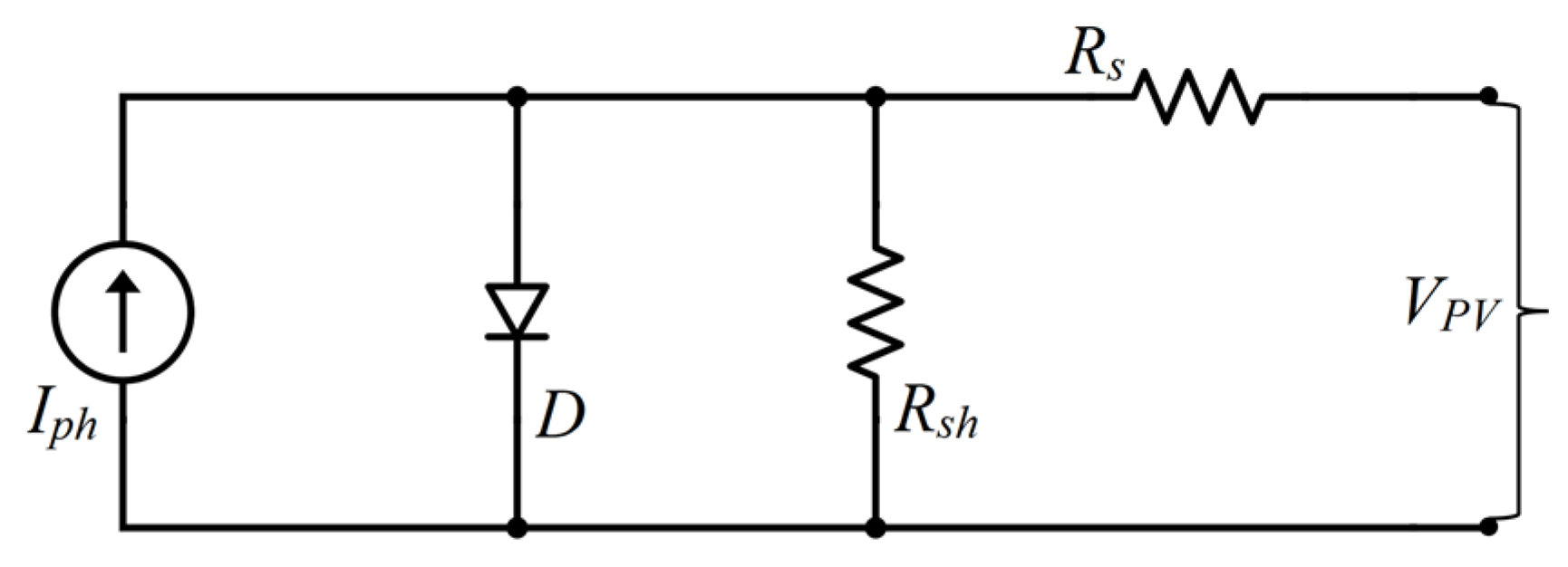
The solar PV system serves as the primary renewable energy source for the microgrid. It consists of solar panels that convert solar irradiation into electrical energy. Solar cells function as semiconductor elements. When sunlight penetrates the PV cells’ surface, a direct current (DC) flows through the photovoltaic panels. The equivalent electrical circuit of a PV cell is depicted in Figure 2, known as the one-diode model. This model consists of a current source, a single diode, and a pair of resistors.
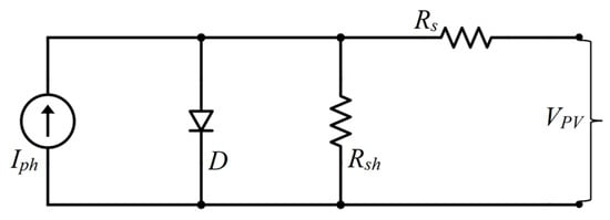
Figure 2.
One-diode model of a PV panel.
The output current of the PV cell can be derived using Kirchhoff’s law,
Here, is the photo-generated current, ID is the diode current, is the shunt current, VPV is the output voltage of the PV cell, is the series resistance, and is the shunt resistance.
The diode current ID follows the Shockley equation,
where I0 is the reverse saturation current, K is Boltzmann’s constant, q is the elementary charge, n is the ideality factor of the p-n junction, and T is the temperature of the PV cell.
Substituting Equation (2) into Equation (1) yields the I–V characteristics of the PV cell,
The photo-generated current IPV depends on temperature T and irradiance G, as shown,
where ISC is the short circuit current at 25 °C and 1000 W·m−2, and Ki is the temperature coefficient of ISC.
PV modules typically consist of multiple PV cells arranged in series (M) and parallel (N) configurations. The module’s output voltage V and current I are determined by the following:
Substituting these into the I–V characteristic equation for a PV module yield the following:
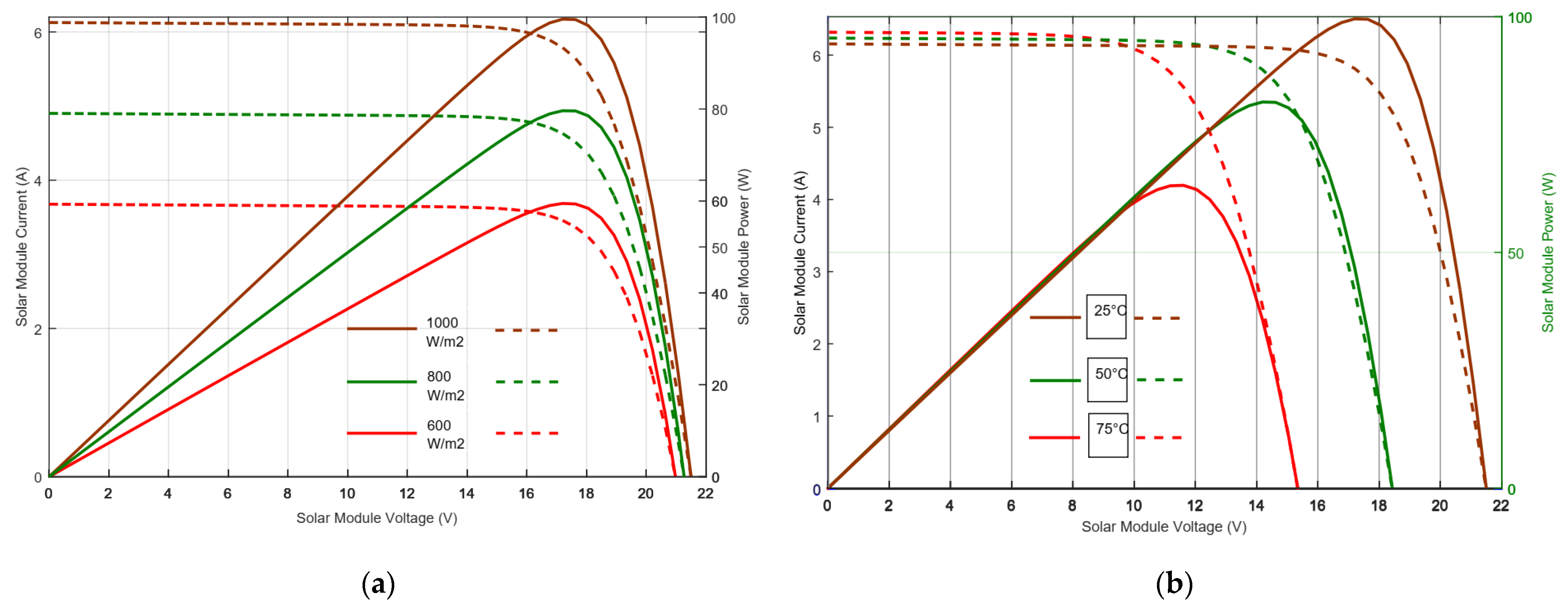
This expression illustrates the relationship between a PV module’s output voltage and current with M × N cells, showing how climatic conditions such as solar irradiance and temperature impact the P–V and I–V curves, as seen in Figure 3a,b.
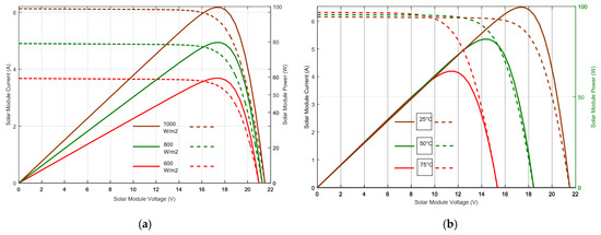
Figure 3.
(a) P–V and I–V curves at variable irradiance and constant temperature of 25 °C; (b) P–V and I–V curves at variable temperature and constant irradiance of 1000 W·m−2 [23].
Moreover, an additional simplified approach may be considered to model the solar PV system, where the output power equation will represent the PV. A maximum power point tracking (MPPT) system is employed to maximize the energy capture from the solar panels. The MPPT system utilizes a perturb and observer P&O to determine the optimal operating voltage for the solar panels. However, numerous research studies [24,25] begin using a PI controller with MPPT when there is excess power and the batteries are fully charged. In such cases, the system switches to PI to maintain stability. The following equation can determine the PV system’s hourly electrical output (PPV) [21].
where I is the solar irradiation in kW/m2, To is the temperature in C (Celsius), is the efficiency, and S is the area in m2 of the solar cell array.
2.2. Battery Energy Storage System
Incorporating a battery energy storage system (BESS) significantly improves modern energy infrastructure. This technology offers a diverse and effective method for storing and releasing electrical energy. A BESS can store excess power during periods of low demand and provide it at peak demand or during system interruptions [14].
The electrical model of the battery is crucial for understanding its behavior and interaction within the microgrid. The second-order RC equivalent circuit model of a lithium-ion battery is shown in Figure 4. The commonly used model includes an open-circuit voltage source , an internal resistance , and a parallel combination of polarization capacitance C and polarization resistance representing self-discharge. The battery’s terminal voltage can be expressed without considering the polarization component as follows:
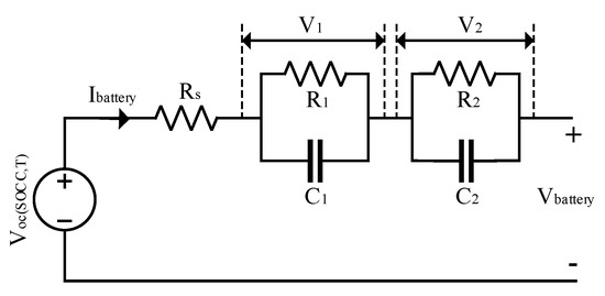
Figure 4.
Second-order RC equivalent circuit model.
Where is the battery current. The open-circuit voltage is a function of the state of charge (SOC) and the internal resistance . However, considering polarization resistors, R1 and R2 and polarization capacitors C1 and C2:
The dynamic behavior of the battery, including charging and discharging characteristics, can be modeled using equivalent circuits that capture transient responses. For example, the Thevenin model includes an additional RC network to represent transient voltage behavior during rapid current changes.
2.3. Load Model
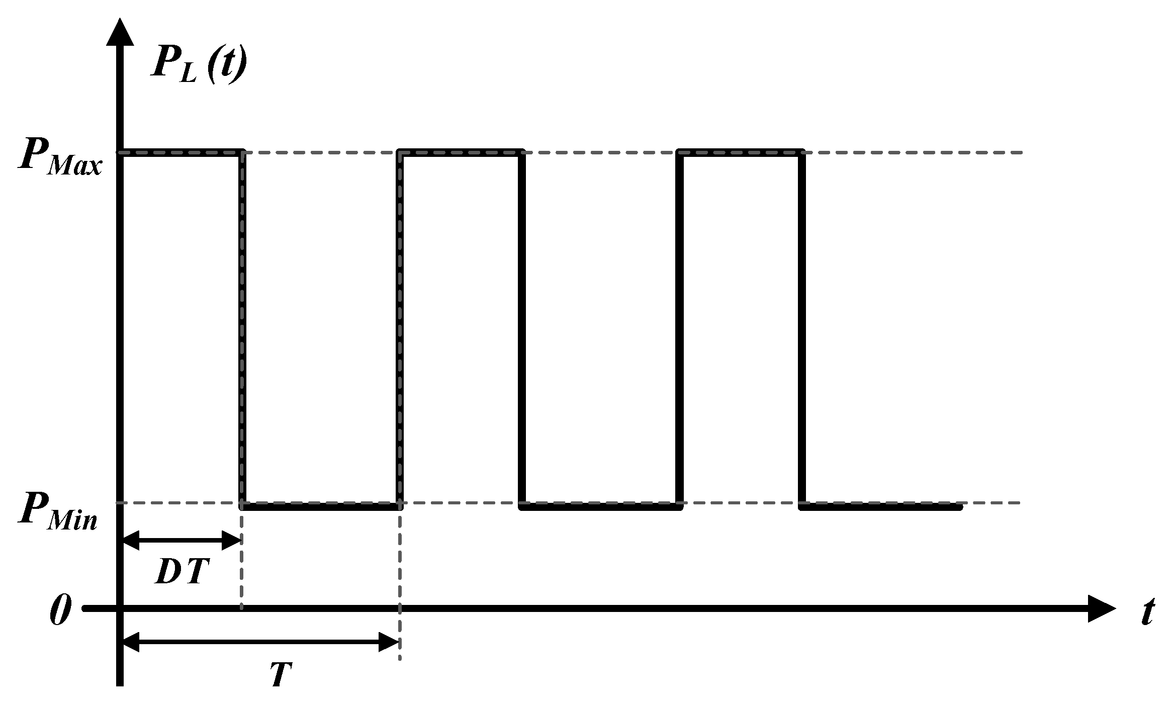
The pulse load profile, as depicted in Figure 5, is characterized by a high-power demand that oscillates between a minimum power level (PMin) and a maximum power level (PMax) over a defined period (T). The frequency of this load can be expressed as F = 1/T, indicating how often the load cycles between its minimum and maximum values within a given timeframe. Additionally, the duty cycle of the load is a crucial parameter; it quantifies the proportion of the period T during which the load is active. This duty cycle is essential for understanding the load’s impact on the system, as it represents the percentage of time within each cycle that the maximum power demand is exerted.
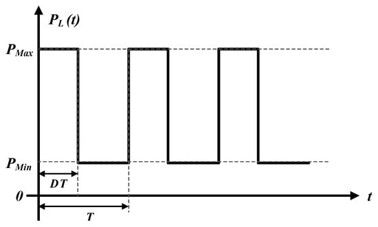
Figure 5.
Pulse load profile.
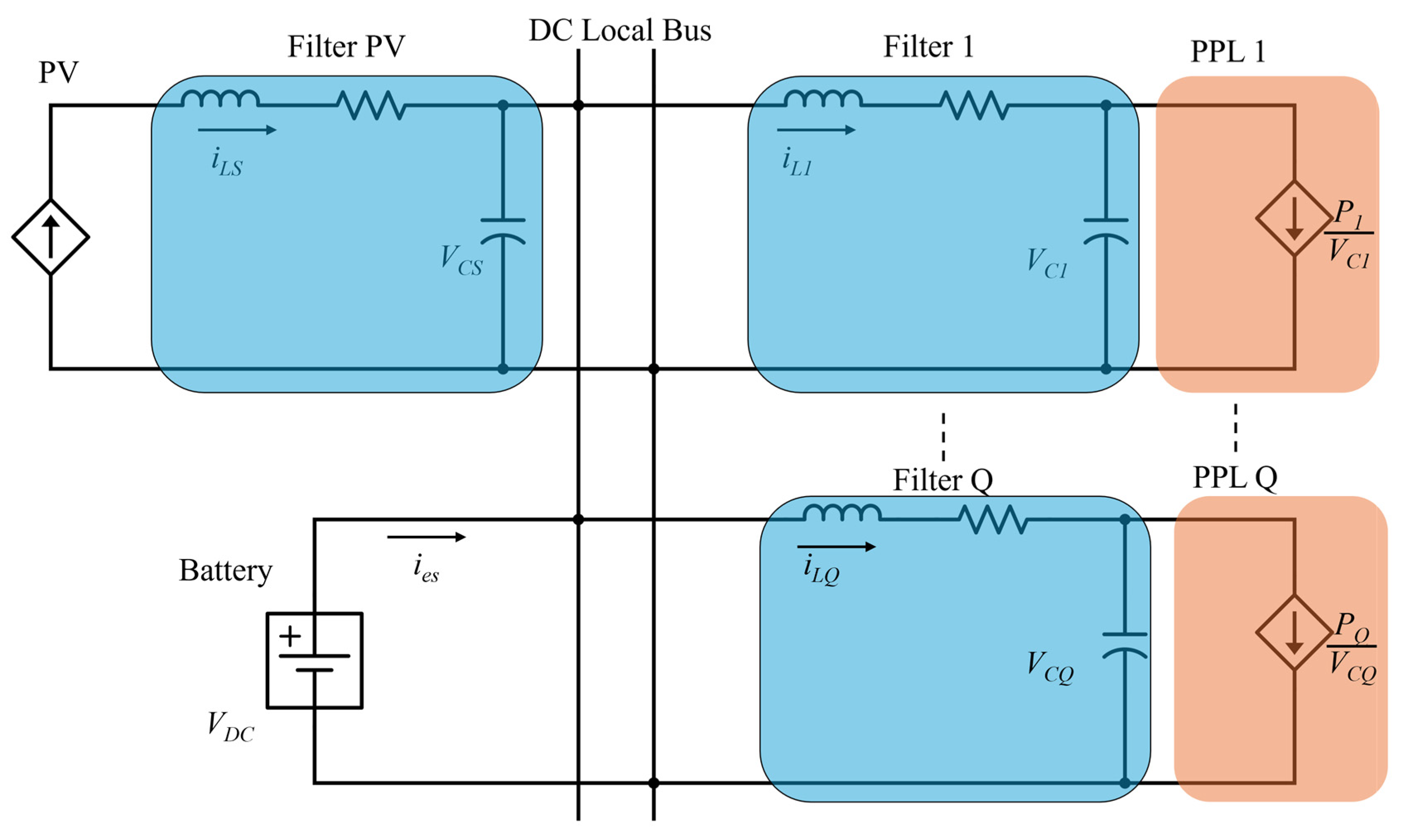
Our proposed architecture examines resistive and pulsed power loads (PPLs) ad illustrated in Figure 6. We model PPLs as voltage-controlled current sources with power levels switching between Pj = PL (when active) and Pj = 0 (when inactive). The DC bus voltage VDC remains constant, and the injected current stabilizes the system during PPL operation. RLC filters, including supercapacitors for high capacitance and fast response, stabilize the overall system and manage fluctuations from the PPLs.
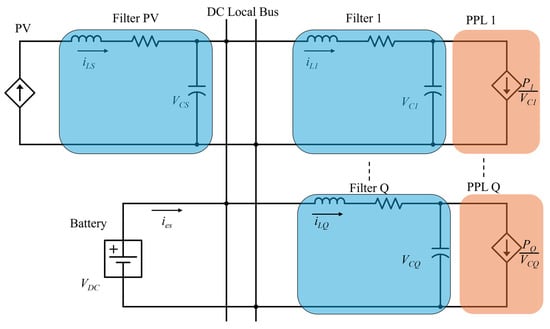
Figure 6.
Subsystems of the DC microgrid system.
Now, the state space representation of the source subsystem [26,27] is,
where, , iL,s is the currents of the inductor, vC,s is the voltage of the capacitor in the ESS, and,
Now, the state space representation of the filter of the PPLs [28],
where, iL,j is currents of the inductor vC,j is the voltage of the capacitor in the jth PPL, and,
The state space representation of the overall DC MG will be [29,30],
where
2.4. DC-DC Bidirectional Structure
A bidirectional converter is a power electronic device that can operate during both discharging (Boost mode) and charging (Buck mode). This device is critical in various applications, including renewable energy, electric vehicles, and battery management [31,32]. One of their key features is that these converters have the same transfer function in both operating modes. This suggests that whether the bidirectional converter operates in boost or buck mode, the mathematical equation controlling its input and output remains the same. As such, a single controller can efficiently manage both operating modes. This unified method streamlines the control architecture and ensures smooth transitions and operation by enabling a single controller unit to oversee both the boost and buck operations [33,34].
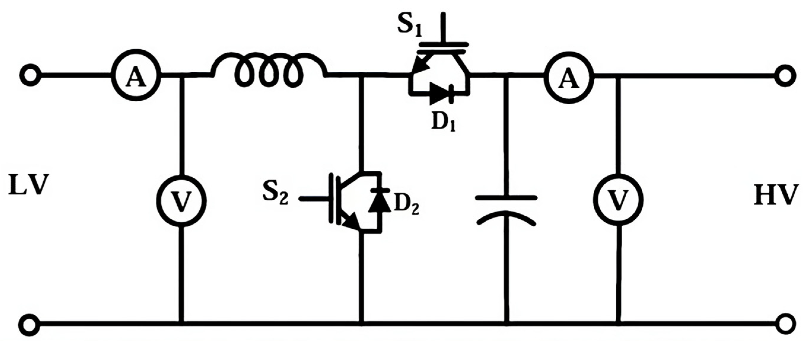
Figure 7 shows the boost and buck modes of operation for the bidirectional converter. IGBT S2 transfers energy from the low-voltage (LV) to the high-voltage (HV) terminal while in boost mode. When S2 is turned on, the capacitor releases energy to the HV terminal, and the inductor is charged. Capacitor C is charged by a current passing through the inductor and diode D1 when S2 is off.

Figure 7.
DC-DC bidirectional converter topology.
IGBT S1 transfers energy from the HV terminal to the LV terminal while in buck mode. When S1 is activated, current flows to the LV terminal via the inductor. The inductor’s stored energy flows via diode D2 when S1 is off, continuing the current flow until S1 returns.
3. Proposed Control Scheme
3.1. Photovoltaic Control Scheme
Figure 1 illustrates the system control of the DC bus voltage Vdc. The DC bus voltage regulation must generate reference currents for the bidirectional converters. The control strategy for the PV system, shown in Figure 1, employs two distinct control loops to manage the system effectively:
- Proportional Integral (PI) Control Loop: This loop takes over when the battery reaches its maximum charge. The PI controller manages the PV array boost converter, which supplies the power required to adjust voltage levels. This regulation is crucial for assuring the stability of the DC bus voltage, preventing battery overcharging, and keeping the voltage within acceptable limits.
- Maximum Power Point Tracking (MPPT) Control Loop: This loop activates when the battery is not fully charged. The MPPT controller employs the “Perturb and Observe” algorithm to constantly modify the operating point of the PV array to harvest the most feasible power. This power is utilized to satisfy the current load requirements. If the PV array produces any excess electricity, it recharges the battery.
3.2. Conventional PI-PI Control Scheme
The PI-PI double closed-loop control strategy is integral to managing the charging and discharging processes in battery systems within DC microgrids. This method involves two PI controllers working in tandem to ensure precise voltage and current regulation. Initially, comparing the DC bus voltage Vdc and the reference voltage Vref* generates an error signal. This error signal is amplified to produce the desired current reference Iref*, which directs the current needed to achieve the target voltage. A critical aspect of this process is the constant current (CC Mode) control during the charging phase. At this stage, it is essential to limit the current reference to an optimal level to regulate the inductor current accurately. This measure is vital for maintaining system stability and preventing overcurrent issues that could damage the battery or the power converter.
The inner current control loop operates parallel to the outer voltage control loop, focusing specifically on the real-time regulation of the charging or discharging current. This is accomplished using current sensors that continuously monitor the current flowing into or out of the battery. The measured current is compared against the desired current setpoint, and any deviation generates an error signal. The inner PI controller then adjusts the voltage applied to the battery to correct this error, ensuring the current aligns with the setpoint. To implement these adjustments, the output of the current control loop is compared with a triangular waveform to generate the Pulse Width Modulation (PWM) signal for the bidirectional converter switches. This PWM signal determines the duty cycle () of the switches, directly influencing the voltage and current delivered to the battery. The precise control afforded by the PI-PI strategy helps prevent overcharging and deep discharging.
The effectiveness of the PI-PI control strategy is emphasized by its mathematical representation through transfer functions. The transfer function that describes the relationship between the inductor current and the output voltage is given by the following:
The following equation describes the transfer function of the voltage compensator. The parameters that result are established as follows: = 2 and = 107
The transfer function guiding the control of the inductor current is as follows:
The following equation describes the transfer function of the current compensator. The parameters that result are established as = 0.1 and = 102
These transfer functions are fundamental for designing and tuning the PI controllers for optimal performance. They illustrate how the system parameters, such as battery resistance (), inductance (), and capacitance (), interact to influence the current and voltage dynamics. By carefully tuning these parameters, the PI-PI control scheme can provide robust and efficient control, enhancing the overall stability and performance of the DC microgrid under various operational conditions.
3.3. Neural Network Structure
The DC standalone microgrid, as proposed, uses a controlled charging and discharging strategy that accounts for the available power from the photovoltaic system and the determinant load requirements. In this approach, a double closed-loop control is applied. The outer loop incorporates a Neural Network-based controller for voltage control. A neural network controller using a recurrent neural network has been chosen here; such a type of neural network is usually used to simulate time-varying and dynamic problems [35,36,37,38]. Those are significant characteristics that a control system in a microgrid must have to control voltage variation efficiently. The system design includes the recurrent neural network (RNN) controller as its core part, which provides the following distinct features. It takes in two significant inputs: the error in the difference between the reference voltage and the measured DC bus voltage and the derivative of the error. The recurrent nature of this form of RNN, with the attribute of remembering the previous states [39,40], allows the network to learn and understand periodic trends and guess precisely what the correction in control signals must be. This would generate much more refined and intelligent voltage control compared to some feed-forward neural networks. An example output is the setpoint current signal produced by the RNN to illustrate the optimum current necessary for keeping the desired spacing voltage.
This setpoint current signal is later subtracted from the measured actual battery current, and the error lessened is fed into a PI controller of the inner loop. The PI controller fine-tunes the control with the conduction duty cycle to minimize the current error. Its output is further evaluated to modulate the switching of the bidirectional converter by comparing it to a triangular wave to ensure the efficient power transfer between the PV system, the battery, and the loads.
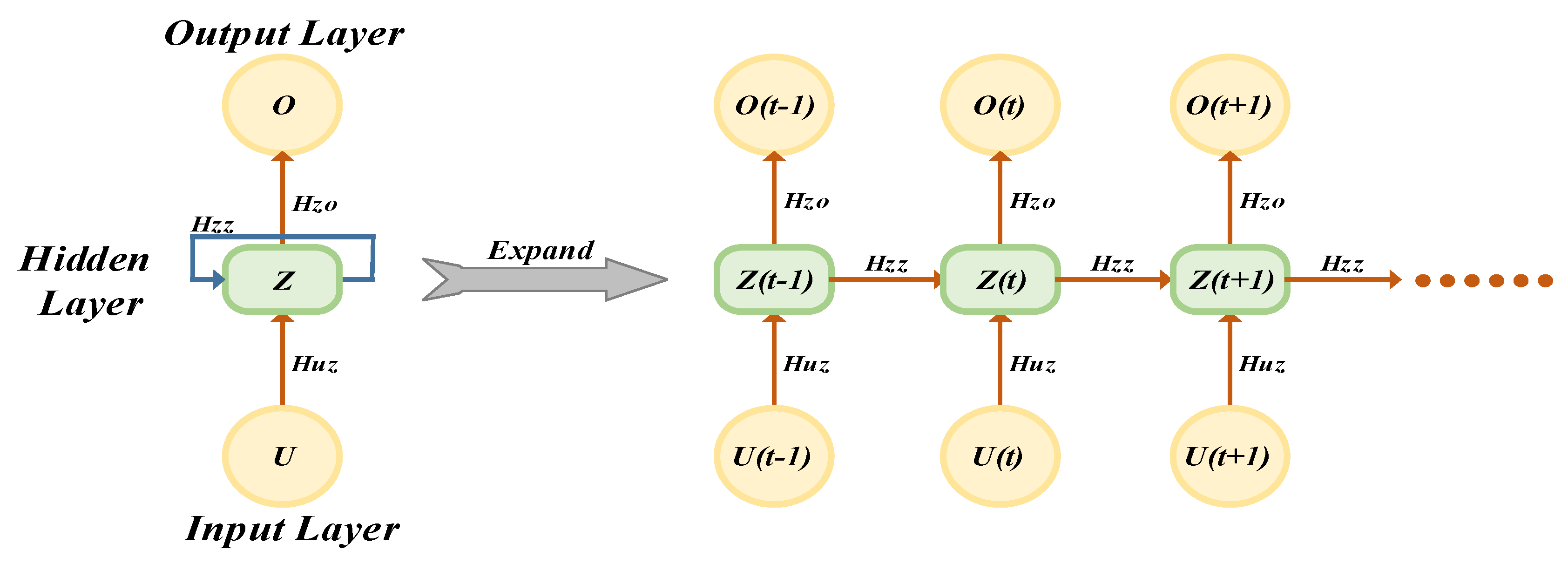
RNNs implement a multilayer network architecture through which the forward and recurrent connections go into the earlier layers, as shown in Figure 8. In this way, the RNN integrates information over time and yields a robust method to predict and adapt changes in the system. Standard RNNs go through Equations (22) and (23) from t = 1 to T to compute the hidden vector sequence Z = (Z1, …, Z(t+1)) and output vector sequence O = (O1, …, O(t+1)) given an input sequence U = (U1, …, U(t+1)).
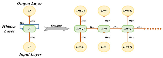
Figure 8.
Recurrent neural network structure (RNN).
In the equations above, , , and represent the weight matrices for the input-to-hidden, hidden-to-hidden, and hidden-to-output connections, respectively. The and terms are the bias vectors for the hidden and output layers, respectively. The function denotes the activation function for the hidden layer, typically implemented as an elementwise sigmoid function. Figure 8 illustrates the RNN structure and how it unfolds over time during the forward computation. In this setup, artificial neurons receive inputs from neurons at previous time steps [41,42].
The learning of the RNN is carried out very carefully by using the historical data of the microgrid to train the weights, which in turn churns out highly accurate results by modeling the relationship between the voltage deviations and necessary corrective actions, a crucial step in developing an advanced control strategy of our kind. What makes the proposed RNN method superior to the conventional Proportional-Integral control is the higher-order processing of dynamical and, most of all, time-varying information. It is commonly known that PI controllers may only sometimes be able to handle changing circumstances and nonlinearities in the system when working with fixed parameters. RNNs, on the other hand, can learn from historical data.
Therefore, the RNN can forecast system disturbances and modify the relevant control signals to achieve more precise and steady voltage regulation. Because of the memory capability of RNNs, they can learn the complex temporal patterns and dependencies that a PI controller is incapable of, resulting in a much more responsive and robust control system.
3.4. PI-NN Control and Operation
The proposed control system for our DC standalone microgrid utilizes a Recurrent Neural Network (RNN) to enhance the efficiency and stability of battery charging and discharging operations. The main control aim is to regulate the DC bus voltage (VDC) efficiently and precisely to its specified reference value (V_ref). Conventional control techniques, such as the double closed loop Proportional-Integral (PI) controller, face difficulties when faced with the dynamic and non-linear load characteristics encountered in microgrid scenarios. Our method utilizes an RNN to analyze the voltage error and its derivative. This process generates a reference current, which is then sent to a secondary PI controller. The PI controller calculates the accurate duty cycle for the switches’ pulse-width modulation (PWM) in the bidirectional converter, efficiently controlling the power flow to and from the battery.
Incorporating the RNN signifies a significant advancement in our control technique, offering new approaches to microgrid control. The RNN design, consisting of an input layer for the error and its derivative, hidden layers with neurons utilizing activation functions, and an output layer that generates the reference current, illustrates the unique capabilities of the method. This configuration enables the Recurrent Neural Network (RNN) to comprehend and adjust to time-based relationships and immediate fluctuations and disruptions in the microgrid. As a result, it achieves superior response during transient periods and reduces the occurrence of steady-state inaccuracies. Previous testing on a Dspace platform with a standard PI control system provided the neural network’s training data. This dataset contains a variety of operating scenarios and microgrid dynamic responses, ensuring that the RNN is well-trained to deal with the complexity and nonlinearities found in real-world applications. The suggested RNN-PI control system has achieved an efficiency of 98.2%. This excellent efficiency demonstrates our control method’s durability and precision in maintaining the DC bus voltage at the prescribed reference value (V_ref), even under dynamic and non-linear load situations.
The primary control goal is to regulate the DC bus voltage (VDC) effectively and accurately to the given reference value (V_ref). Conventional control systems, such as the double closed-loop Proportional-Integral (PI) controller, struggle when confronted with microgrid circumstances’ dynamic and nonlinear load characteristics. Our solution employs an RNN to assess the voltage error and its derivative, sending a reference current to a secondary PI controller. The PI controller determines the precise duty cycle for the DC-DC converter’s pulse-width modulation (PWM) switches, allowing it to manage power flow to and from the batteries efficiently. Incorporating the RNN is a substantial breakthrough in our control strategy, providing new microgrid control methods.
4. Simulation Results
In this section, we will discuss the efficient operation of the proposed control scheme under different operational scenarios using MATLAB/Simulink (R2022b). The resilient and stable operation of the standalone DC microgrid across severe operating conditions, including the impact of PPL on voltage stability, is evaluated through extensive simulation analysis. Moreover, the superiority of the proposed hybrid control scheme in enhancing the system’s transient stability over the conventional PI-PI control scheme is demonstrated as a comparative study. The investigations include three phases, starting with assessing the performance of the proposed system under step-change in the total connected load; after that, the effect of PPL on the system stability is evaluated. Two types of PPL will be studied: firstly, constant PPL, which has continuous power demand with the same rate of change during the running time, and secondly, variable PPL, which has different power demand with variable frequency during the system operation. During each of the scenarios above, a comparative analysis is demonstrated to show the effectiveness of the proposed control scheme over the conventional PI controller in improving the proposed system’s DC bus voltage transient stability. Table 2 presents the proposed system’s rating and parameter values.
Table 2.
The proposed DC microgrid’s simulation parameters.
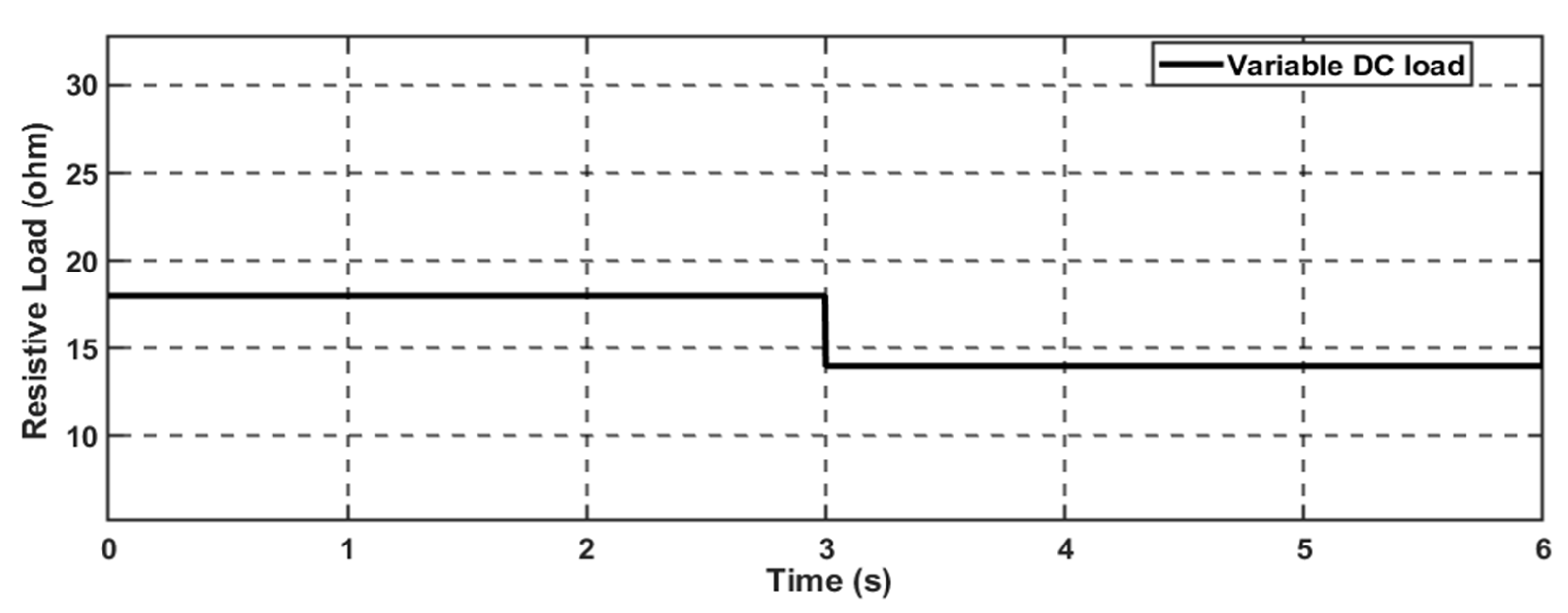
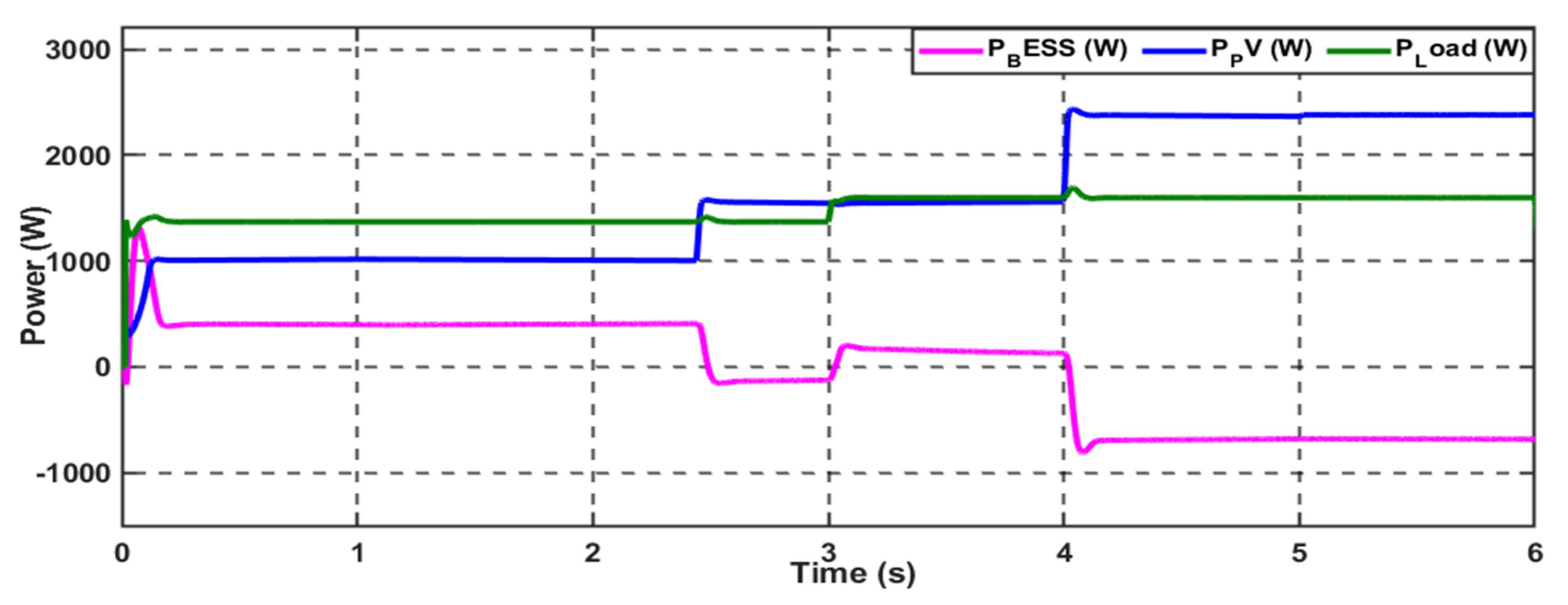
4.1. Scenario 1: Variable DC Load
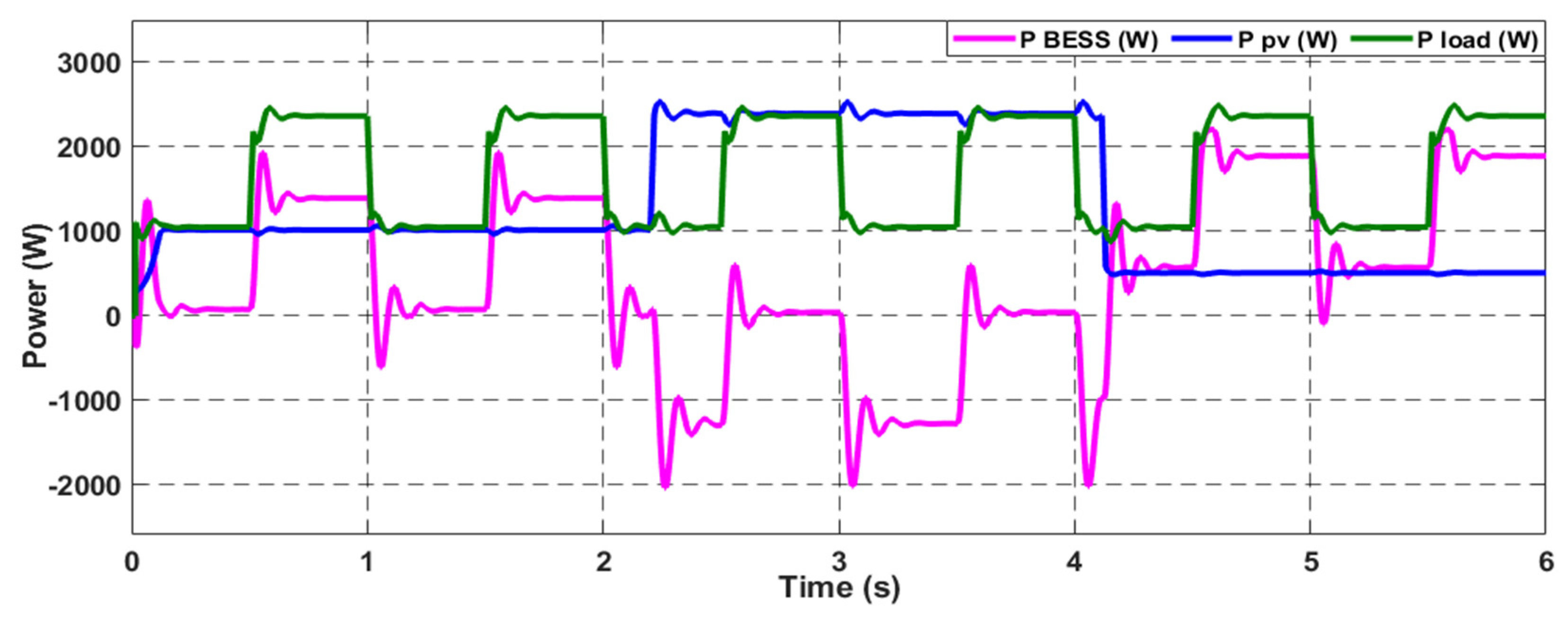
In this case study, the effectiveness of the proposed control scheme in enhancing the DC microgrid stability is evaluated under a standard variable DC load with a 20% step-down change in the total connected load; the load profile is demonstrated in Figure 9. This load profile is represented by a variable resistance connected to the common bus of the DC microgrid. Firstly, the performance of the proposed system was investigated with the conventional PI-PI control scheme; the system can supply the load with the requested power through the hybridization between the PV generation system and the battery, as Figure 10 depicts. The MG exhibits variations in solar radiation at a time equal to 2.5 s and 4 s; the combination of the PV and battery can fulfill the load demand. The system can supply the load when a step-down change occurs at t = 3 s.
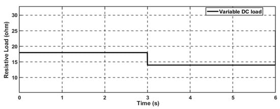
Figure 9.
Variable DC load with a step-down change.
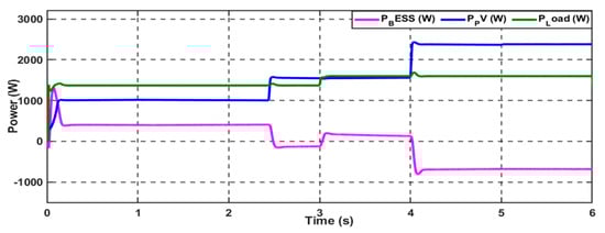
Figure 10.
Power generation from the standalone DCMG uses PI−PI control scheme (Scenario 1).
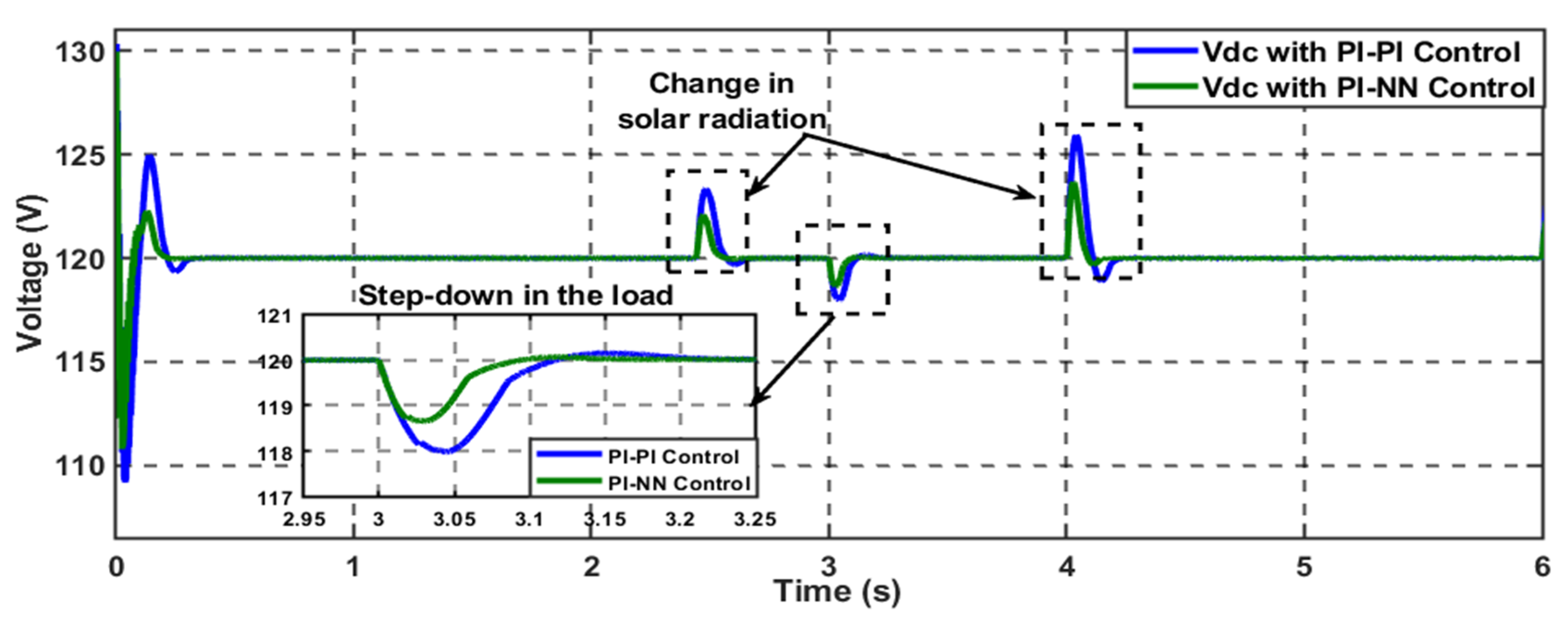
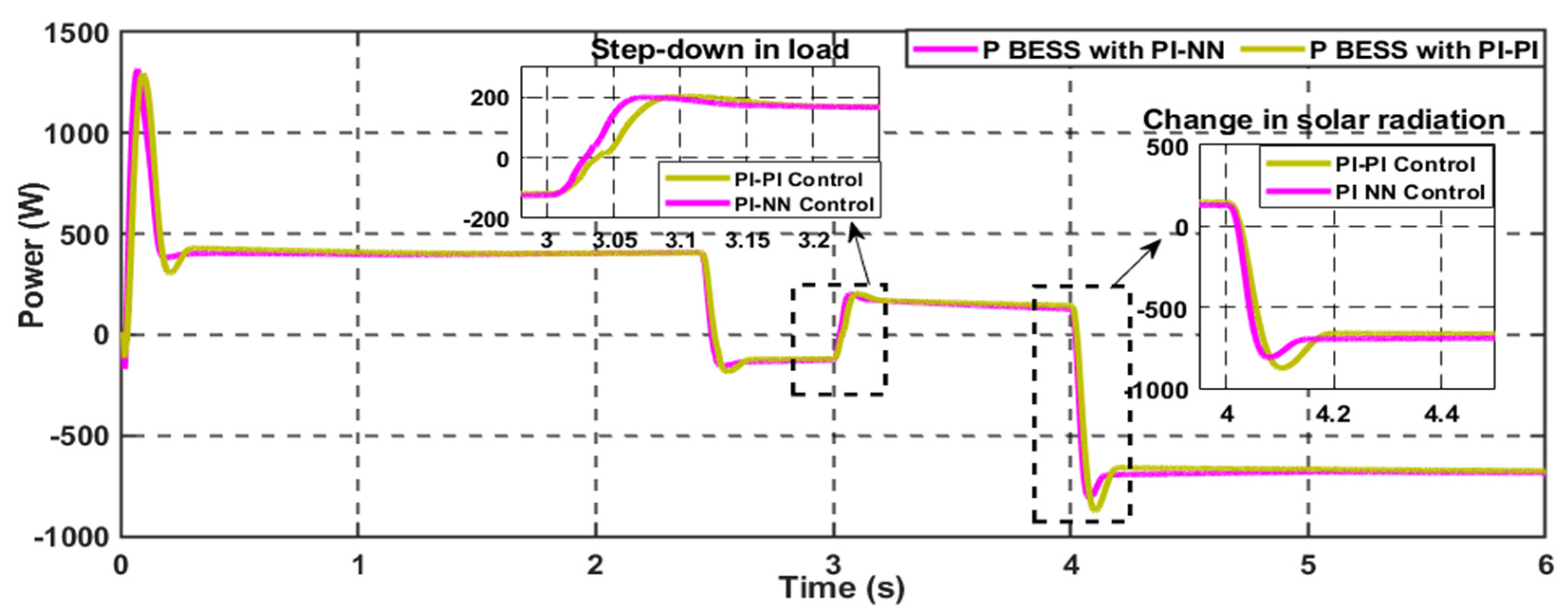
To enhance the system’s transient stability, the system’s performance was evaluated, employing the proposed hybrid control scheme under the same operating conditions. As shown in Figure 11, the proposed control scheme can improve the common DC bus voltage stability in terms of decreasing the settling time (Ts) and the percentage maximum peak (%Mp) values when the system faces changes in load variation and solar radiation due to the adaptability behavior of the proposed control scheme. On the contrary, the conventional PI-PI control scheme has fixed gains that cannot be changed during the system’s operation. Thus, it cannot cope perfectly with the changes during system operation. Furthermore, the performance of the generated power from the battery has been improved, as presented in Figure 12. We can summarize the key performance indicators for enhancing the system’s transient stability using the proposed control scheme, the minimization of the settling time, and the system’s maximum peak. The transient performance of the common DC voltage has been improved with a 4% decrease in the system settling time and a 3% depreciation in the %Mp value. It is worth mentioning that this load profile must be considered a manageable change that affects the system’s resiliency and stability. Thus, while the PI-based BESS control scheme can manage these challenges, the hybrid PI-NN control scheme shows only marginal improvement in transient response.

Figure 11.
Hybrid PI−NN control scheme enhances the DC voltage stability (Scenario 1).
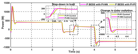
Figure 12.
A hybrid NN−PI control scheme enhances the BESS performance (Scenario 1).
4.2. Scenario 2: Constant Pulsed Power Load (CPPL)
The standalone DC microgrid performance is assessed under constant pulsed power load demand. As demonstrated in Figure 13, this severe load affects the MG stability due to the high-power demand within a short period in a constant repetition; in this test, the total requested load every 0.5 s is increased/decreased by six times from its original value, forming the CPPL demand. Beginning with the conventional PI-PI control architecture, the system can supply the load demand, as shown in Figure 14; however, the BESS experiences continuous stress with a high %Mp during the transition between the minimum and maximum limits of the total connected load.
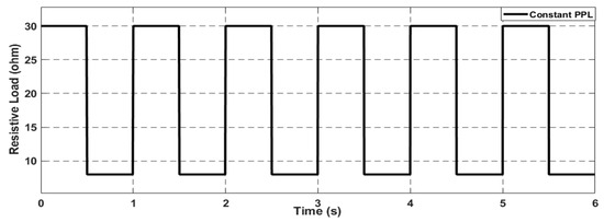
Figure 13.
Constant pulsed power load (CPPL) profile.
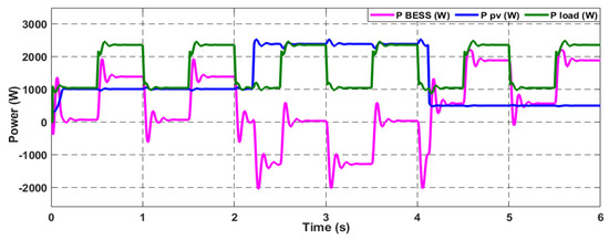
Figure 14.
The power generation from the standalone DCMG uses PI−PI control scheme (Scenario 2).
On the contrary, the stress on the BESS during transients was minimized by 25% from its initial maximum peak value when the hybrid control scheme was utilized, as depicted in Figure 15, which helps increase the BESS’s lifetime. Besides, the oscillations on the generated power from the BESS decreased with a fast action response, and the settling time decreased by 5%. This is due to the online adaptability of the Neural Network during the system operation, which makes the system more resilient and stable under this severe loading condition.
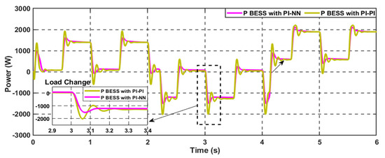
Figure 15.
The hybrid NN−PI control scheme enhances the BESS performance (Scenario 2).
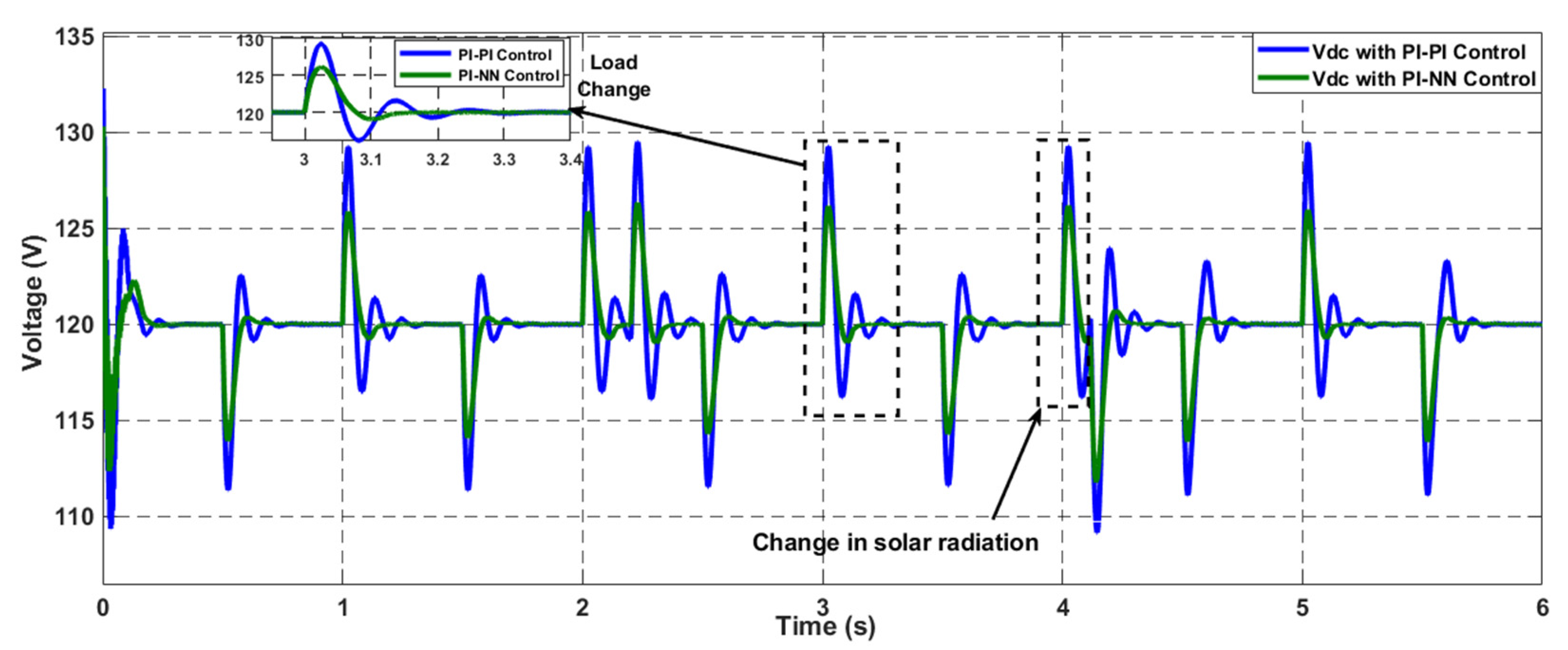
In terms of the DC voltage stability of the MG under the CPPL demand, as Figure 16 demonstrates, the proposed hybrid control scheme has enhancements in the DC voltage stability by decreasing the settling time and the percentage maximum peak of the voltage performance by 6% and 5%, respectively, compared to the conventional PI-PI control.

Figure 16.
The hybrid NN−PI control scheme enhances the DC voltage stability (Scenario 2).
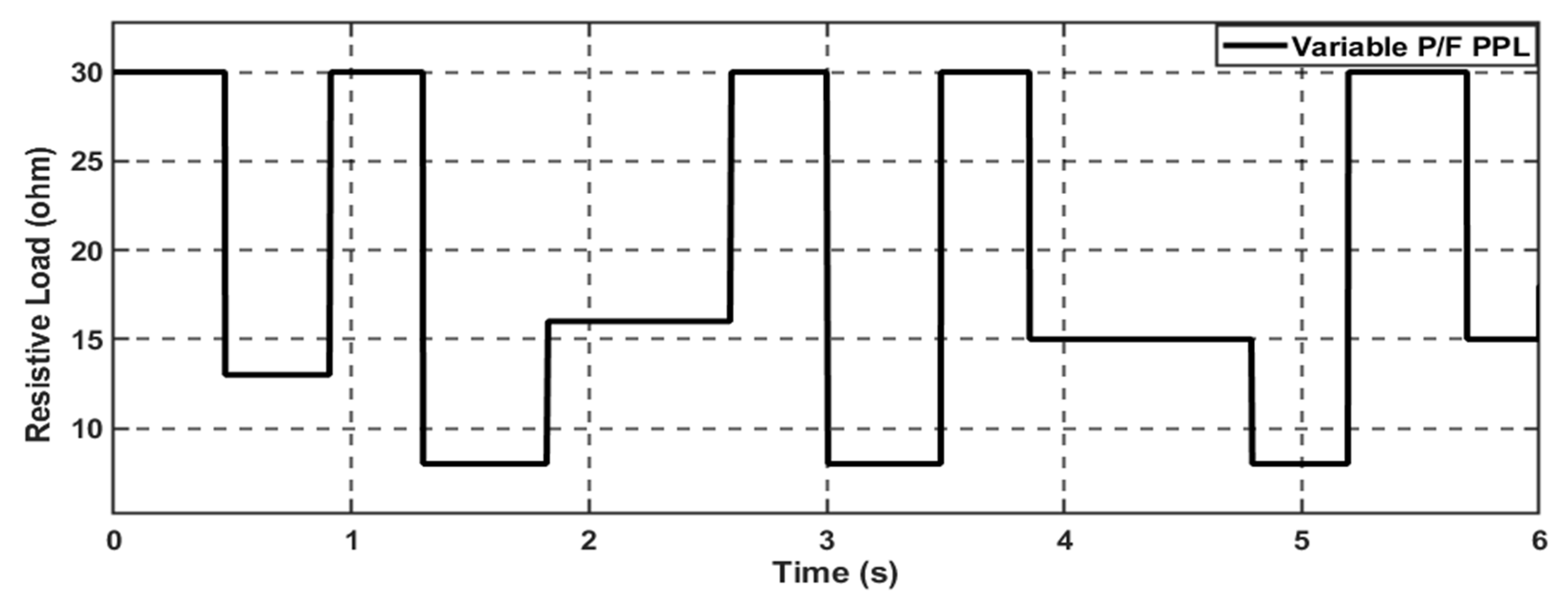
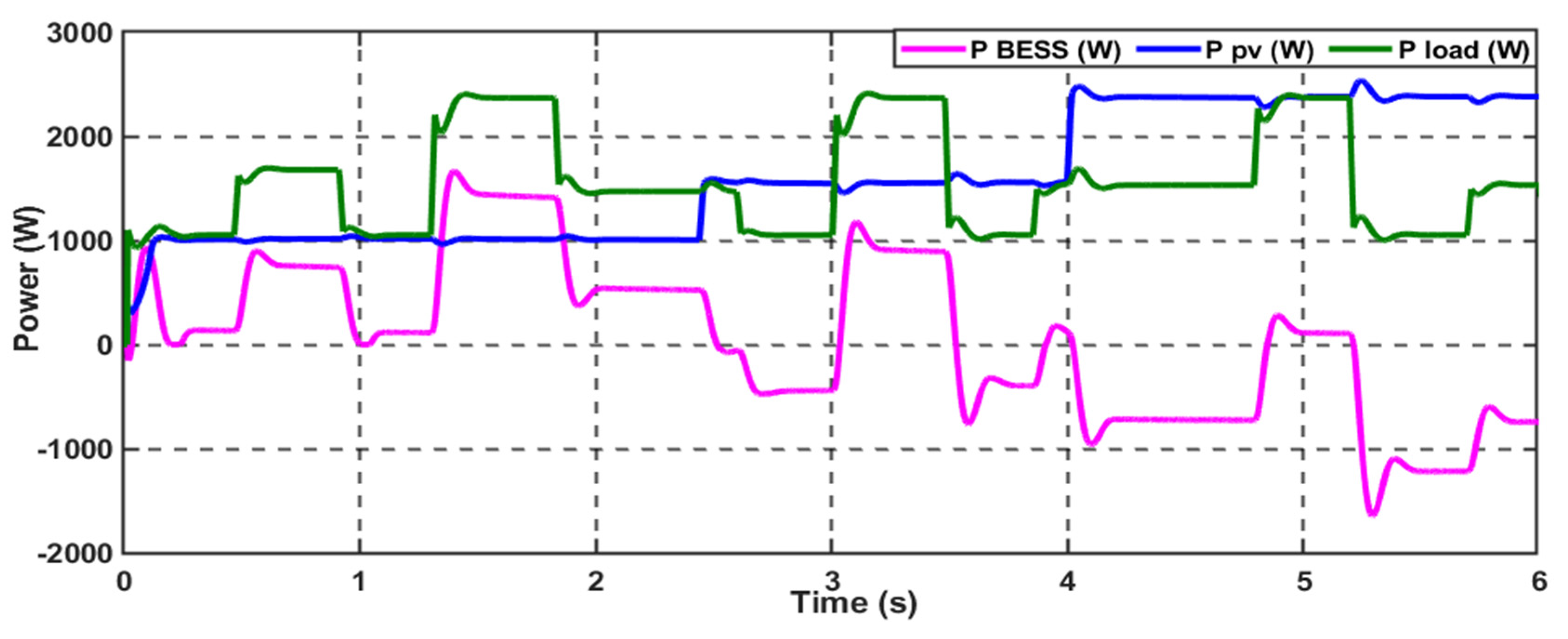
4.3. Scenario 3: Variable Power/Frequency Pulsed Power Load (VPPL)
The impact of the variable pulsed power load (VPPL) on the DC microgrid stability is examined in this simulation scenario. This innovative load profile continuously changes the amplitude of the power demand and varies with different frequencies, as illustrated in Figure 17. This load requirement affects the system stabilization and needs fast action response to sustain the load demand without losing the system stability. Figure 18 demonstrates that the system can supply the load with the required power by combining the PV and BESS, employing the conventional PI-PI controller. However, we used the hybrid control scheme to enhance the system’s transient performance and quickly adapt to the changes during the system operation.
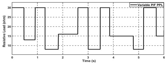
Figure 17.
Variable power/frequency pulsed power load (VPPL) profile.

Figure 18.
The power generation from the standalone DCMG uses PI−PI control scheme (Scenario 3).
Figure 19 and Figure 20 illustrate that the proposed intelligent control scheme has improved the transient performance of the BESS-generated power and the standard DC bus voltage, respectively. This ensures the overall system stability and resiliency under this severe loading condition.
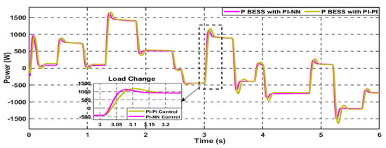
Figure 19.
The hybrid NN−PI control scheme enhances the BESS performance (Scenario 3).
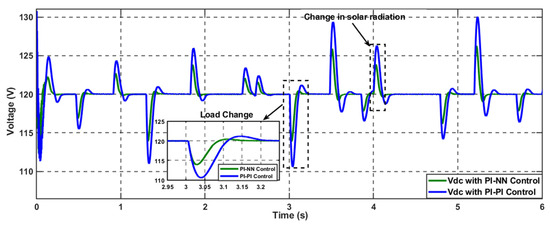
Figure 20.
The hybrid NN−PI control scheme enhances the DC voltage stability (Scenario 3).
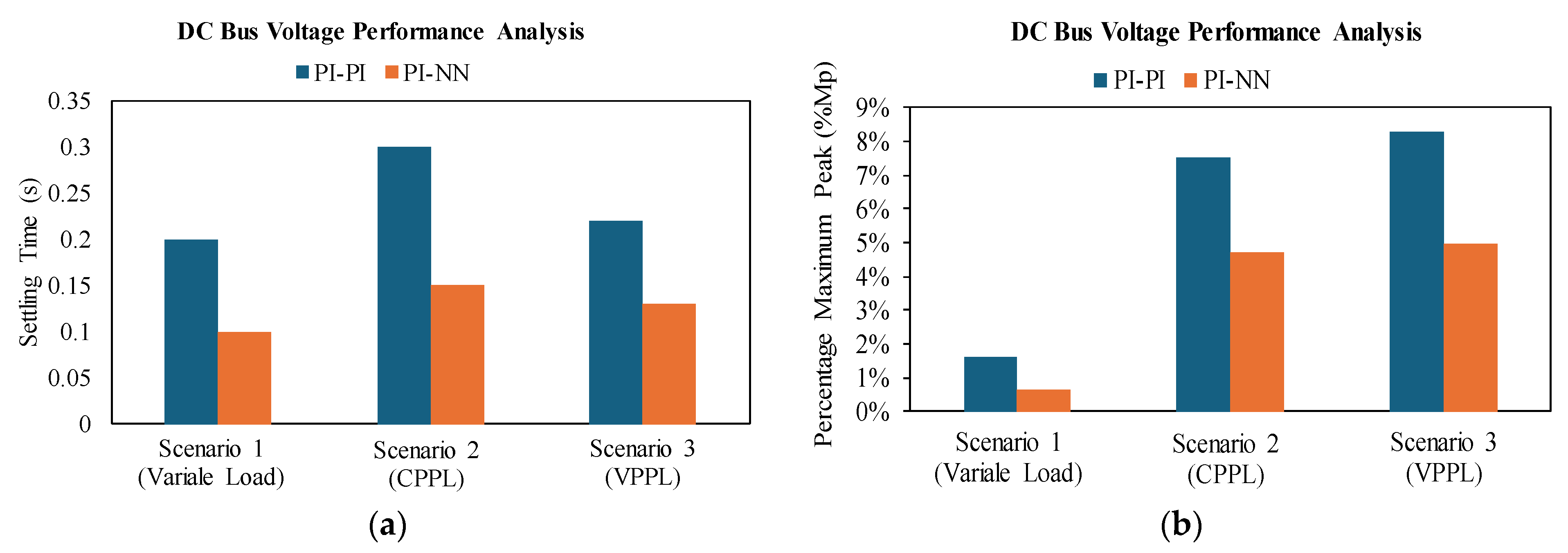
To conclude, the proposed PI-NN control scheme has effectively enhanced the transient stability performance and resiliency of the DC microgrid across various operational scenarios. The enhancement performance matrices of the common DC voltage, employing the PI-NN proposed scheme compared to the PI-PI controller in terms of the settling time and the percentage maximum peak (%Mp), are demonstrated in Figure 21. The proposed scheme improves voltage performance and notably impacts BESS performance, as illustrated in Figure 22, with a faster action response than the conventional PI-PI control scheme.
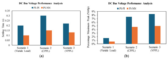
Figure 21.
Overall performance analysis of DC bus voltage: (a) Settling time (s). (b) Percentage maximum peak (%Mp).
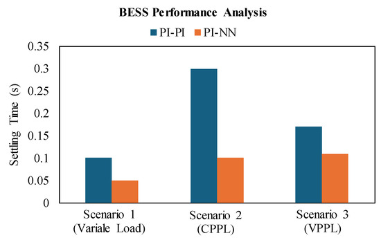
Figure 22.
Overall performance analysis of BESS in terms of enhancing the response time.
5. Hardware and Experimental Results
5.1. Experiment Setup
The experimental validation of the proposed control scheme has been conducted at the FIU smart grid testbed. As shown in Figure 23, the testbed represents a small-scale power system that integrates multiple power sources, either conventional AC power resources represented by synchronous generators or DC power sources, such as PV systems. Besides, various kinds of energy storage systems (ESSs), such as lithium-ion batteries, ultracapacitors, and flywheels, are also used. Consequently, it offers an environment that facilitates developing, testing, and implementing various innovative solutions seamlessly to enhance the DC microgrids’ performance and the overall smart grid systems’ resiliency, reliability, sustainability, and security across various industrial application processes. This flexible hardware environment enables the hybridization between multiple RESs with ESSs through bi-direction bidirectional converters, forming standalone DC microgrid systems, in addition to the ability to integrate multiple microgrids through flexible and secure communication surface with a robust hieratical control scheme to extend the system to the multi-microgrid level of operation. Furthermore, the smart grid testbed can integrate the DC microgrid into the AC side, which represents a small scall utility grid, utilizing bidirectional AC/DC converters. Therefore, we can implement various real-world operational scenarios, with their hardware implementation, that tackle the practical challenges within the smart grids and offer innovative control, protection, communication, and cyber security solutions that can be used in the industry.
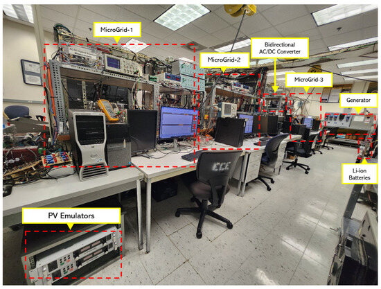
Figure 23.
General overview of FIU smart grid testbed.
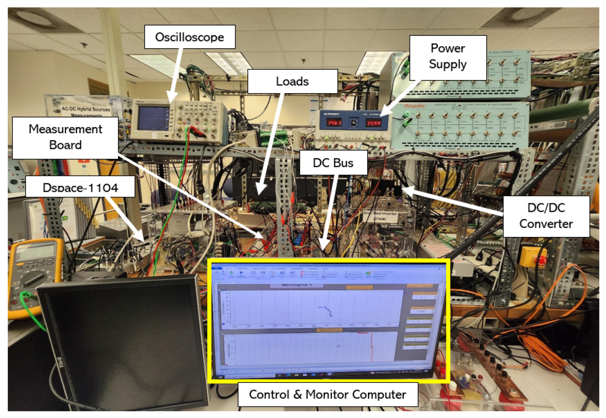
In this paper, we focus on the standalone DC microgrid level of operation, and the proposed control system was evaluated on a laboratory-scale DC microgrid at the FIU smart grid testbed, as shown in Figure 24.
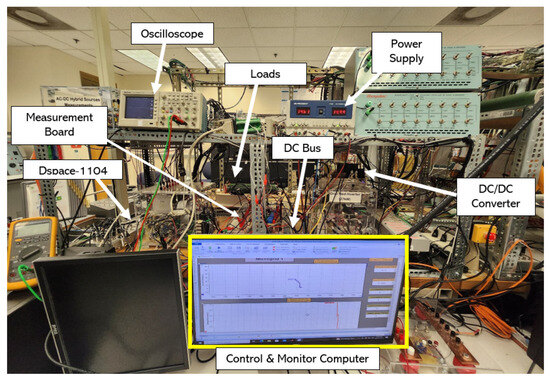
Figure 24.
Hardware implementation of the proposed control scheme in the standalone DC microgrid.
The microgrid includes a photovoltaic (PV) system represented by a Magna Power XRS 175-16/208 (Magna-Power Electronics, Flemington, NJ, USA) pro-grammable power supply. It also includes an energy storage system that uses LiFePO4 RENOGY (12.8 V, 100 Ah, Renogy, Ontario, CA, USA). The core control component, a dSPACE 1104 (dSPACE GmbH, Wixom, MI, USA), is critical for controlling power flow and ensuring high system performance. DC-DC bidirectional converters were used to control energy storage system (ESS) currents. Furthermore, a PPL switching board was built to create a pulsed load profile from resistive DC loads. The DC bus operates at 25 volts. Table 3 describes the hardware setup settings used in the present study.
Table 3.
The proposed DC microgrid’s hardware parameters.
5.2. Scenario 1: Load Step Change—PV Step Change
This work experimentally evaluated the proposed hybrid control method against the conventional PI-PI controller. The results demonstrate the effectiveness of the proposed control method in terms of voltage regulation and the reduction of stress on the energy storage system during the charging and discharging phases. The DC bus voltage, load, battery, and PV currents under the conventional PI-PI controller and the proposed hybrid NN-PI controller are illustrated in Figure 25a and Figure 25b, respectively.
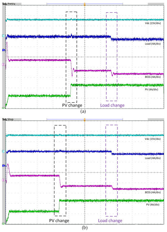
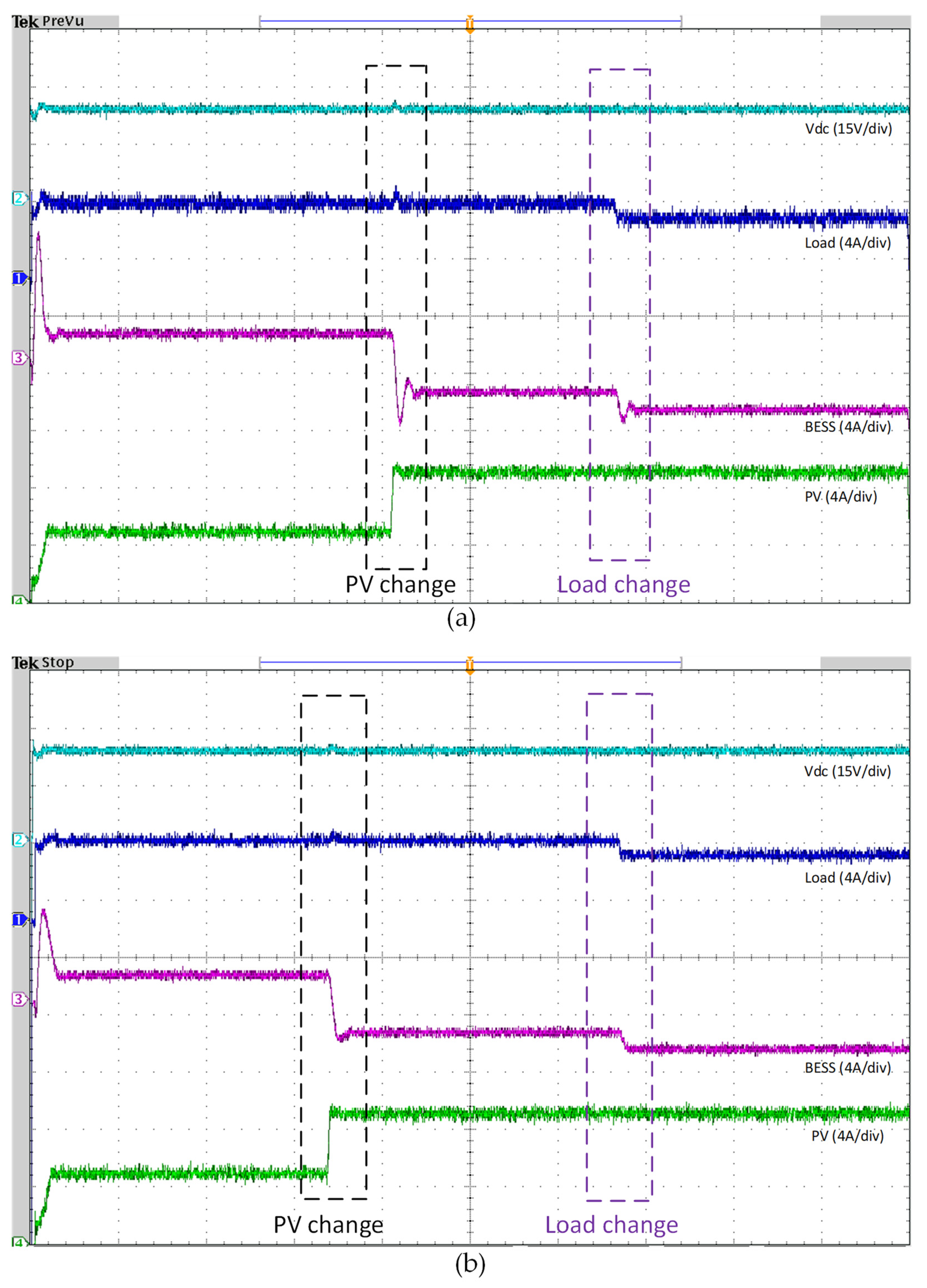
Figure 25.
Experimental validation of the proposed hybrid control scheme with irradiance variation and step load change. (a) Results of PI−PI control algorithm, (b) Proposed algorithm RNN−PI results.
The first disturbance that faces the system occurs at t = 4.3 s, when the PV power is changed while the load remains constant. In this case, the surplus energy is fed into the battery. Figure 25b shows that the hybrid control method has lower fluctuations than the PI-PI controller in Figure 25a. Moreover, voltage fluctuations are considerably minimized with the hybrid control approach. Another challenge affecting the system’s transient stability at t = 6.5 s involves a step-down change in the total connected load, affecting the DC bus voltage and BESS generation performance.
The experimental results show that the proposed hybrid control method can effectively manage the disturbances during the system operation and improve the overall system stability with better performance during transients than the conventional PI-PI method.
5.3. Scenario 2: Constant Pulsed Load
In the second scenario, we examine the impact of a critical load, precisely a constant pulsed load characterized by repeated high power demands at regular intervals. This scenario requires high-performance control and an energy storage system to maintain system stability. The pulse load starts at 75 W and can exceed 200 W with a frequency of 0.1 Hz and a duty cycle of 50%. Figure 26a and Figure 26b present the DC bus voltage, battery, load, and PV current, utilizing the PI-PI control method and proposed NN-PI algorithm, respectively.
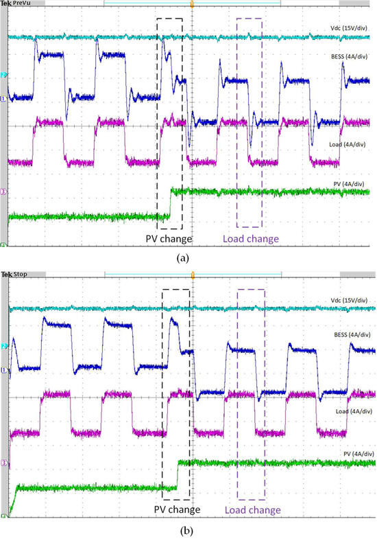
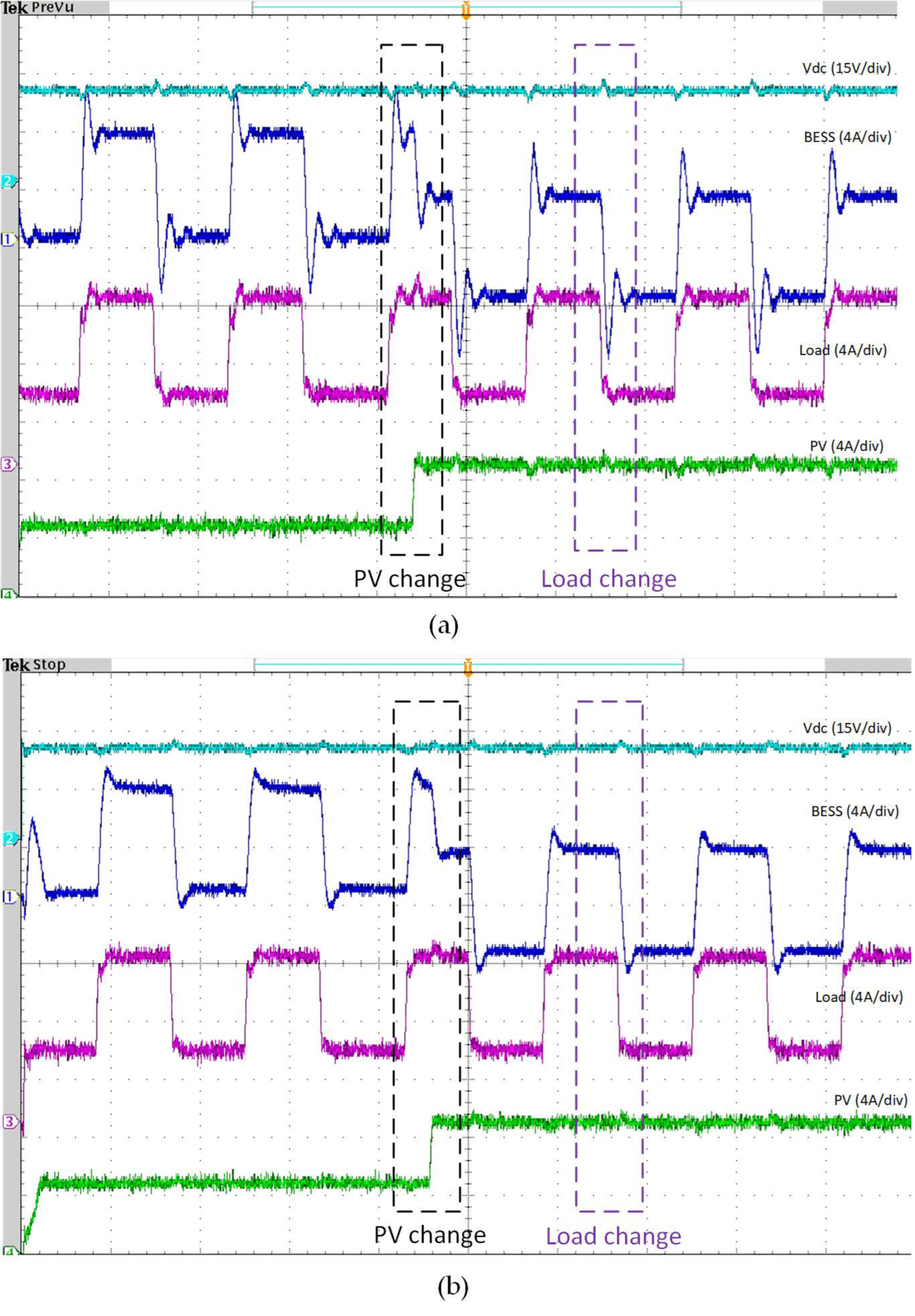
Figure 26.
Experimental validation of the proposed hybrid control scheme with irradiance variation and constant PPL. (a) Results of PI−PI control algorithm, (b) Proposed algorithm RNN−PI results.
Under the conventional PI-PI controller, the DC bus voltage exhibits noticeable fluctuations in response to the pulse load. These fluctuations are significantly reduced when using the proposed hybrid control method, as depicted in Figure 26b.
The constant pulsed load imposes considerable stress on the energy storage system, requiring the system to respond to sudden and notable power demands rapidly. During the pulse load periods, the battery current fluctuates considerably due to the substantial power requested by the load. This indicates significant stress on the battery, primarily due to its reliance on the PV system’s contribution. The PV system at t = 4.2 s experiences a step change, resulting in excess energy during periods of no pulse load, resulting in the battery charging. This dynamic further stresses the battery, as it must constantly adapt to the changing power demands. The rapid charging and discharging cycles can reduce lifespan.
In contrast, the proposed hybrid control method effectively mitigates these issues. The hybrid control minimizes the fluctuations in the DC bus voltage and stabilizes the battery current more effectively than the PI-PI controller. Figure 26b illustrates that the DC bus voltage remains more stable under the hybrid control, and the battery experiences fewer fluctuations even during high power demands from the pulse load. This stability is crucial for maintaining the reliability and efficiency of the energy storage system. The hybrid control method also efficiently manages the energy flow, ensuring excess PV energy is stored in the battery without causing significant stress. By optimizing the energy distribution between the PV system and the battery, the hybrid control strategy enhances the overall performance and reliability of the energy storage system. This approach reduces the battery’s stress and improves the overall system efficiency, demonstrating its superiority over the conventional PI-PI method.
5.4. Scenario 3: Variable Pulsed Load
Within this experiment, we subjected the system to a severe challenge characterized by a variable pulse power load (VPPL), with variation in the amplitude of the requested power and frequency. The performance of the proposed control scheme compared to the conventional PI-PI is presented in Figure 27a,b. During the system operation within this experimental test, the system initially managed acceptably; however, as time progressed, the intervals between pulses decreased, imposing a more significant strain on the battery. This led to a noticeable decrease in the system’s overall efficiency and stability over the long time running of the system.
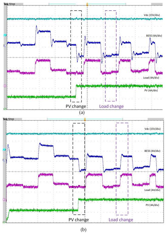
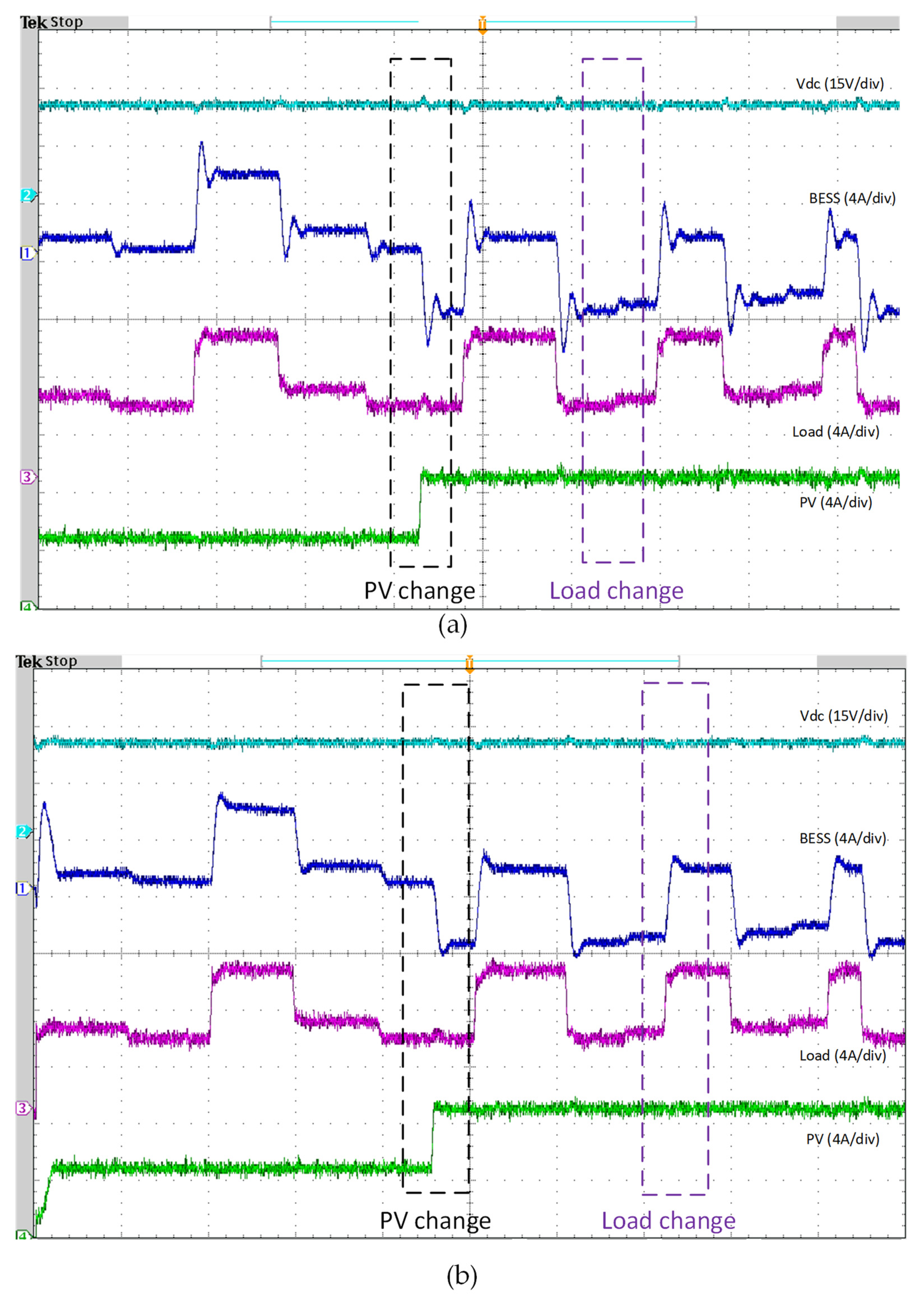
Figure 27.
Experimental validation of the proposed hybrid control scheme with irradiance variation and variable PPL. (a) Results of PI−PI control algorithm, (b) Proposed algorithm RNN−PI results.
As demonstrated in Figure 27a, the DC microgrid, utilizing conventional PI-PI control, can manage the variable pulse load relatively well at the beginning of this test. This is due to the sufficient time intervals between pulses that allow the battery to recover and stabilize. However, as the frequency and intensity of the pulses increased, in addition to the changes in solar irradiance level, the system began to show signs of strain on the BESS performance, with a high overshoot at the transient changes. Consequently, the conventional PI-PI controller struggled to maintain stable DC bus voltage and battery current under these dynamic conditions.
In contrast, the proposed hybrid NN-PI control scheme has enhanced the overall system transient stability, as illustrated in Figure 27b. During this severe operational scenario of high pulsed power load demand with a variable rate of change, the proposed scheme can manage the power-sharing well while decreasing the stress on the BESS during the charging and discharging periods in the forms of reducing the percentage of both over and under overshoot of the generated power. Besides, the overall stability of the common DC bus voltage has been improved with less settling time and %Mp compared to the conventional control scheme.
To summarize, the analysis of both scenarios highlights the significance of an advanced control strategy in maintaining the stability and efficiency of an energy storage system under dynamic load conditions. The hybrid control method outperforms the conventional PI-PI controller by minimizing voltage fluctuations, reducing battery stress, and optimizing energy flow. This enhanced control approach is crucial for ensuring the reliability and longevity of energy storage systems in the face of increasingly demanding and variable loads.
6. Conclusions
This work proposes an innovative hybrid control scheme to enhance the autonomous DC microgrid transient performance across several operating conditions. The proposed hybrid NN-PI control scheme aims to improve the operation of the BESS control loop by enhancing the generated power performance of the BESS and improving the overall transient stability of the common DC bus voltage. The proposed control algorithm has been evaluated under different loading conditions, including pulsed power load (PPL) demand, which is considered a severe challenge within the standalone DC microgrids operation, as they require a high amount of power within a short period, affecting the system stability. The introduced comparative analysis based on the simulation results has proved the superiority of the proposed hybrid NN-PI control scheme over the conventional PI-PI control under various operational scenarios, including constant PPL (CPPL) and variable PPL (VPPL). The enhancement in the transient performance has been evaluated regarding how the proposed scheme has minimized the settling time (Ts) and the percentage maximum peak (%Mp) in both the BESS-generated power and the Common DC bus voltage. This is due to the online adaptability behavior of NN during the system operation, which can compensate for the limitation in conventional PI controllers with fixed gains.
Furthermore, the hardware implementation of the hybrid DC microgrid, integrating the PV generation system and the BESS, has been introduced to provide the platform needed to assess and validate the proposed control scheme. The experimental results demonstrate the effectiveness of the proposed hybrid NN-PI algorithm under real-world operation scenarios over the conventional PI-PI control. Notably, it provides a fast action response under different scenarios, decreasing the %Mp in the DC bus voltage. Furthermore, the stress on the BESS during the transient periods was minimized with less %Mp compared to the conventional PI-PI scheme, increasing the lifetime of the BESS. As a future study, several adaptive control schemes can be developed and tested within the implemented hardware setup to enhance the DC microgrid stability. Besides, we can integrate different kinds of ESS into the MG, such as Ultracapacitors, and examine how this will affect the overall sustainable and stable operation of the standalone DC microgrid.
Author Contributions
Conceptualization, A.A., O.A. and S.M.S.H.R.; methodology, A.A. and O.A.; software, A.A.; validation, A.A.; formal analysis, A.A. and O.A.; resources, A.A. and O.A. and O.A.M.; data curation, A.A. and O.A.; writing—original draft preparation, A.A., O.A., S.M.S.H.R., R.A.T. and A.M.I.; writing—review and editing, A.A., O.A., and O.A.M.; visualization, O.A. and S.M.S.H.R.; supervision, O.A.M.; project administration, O.A.M.; funding acquisition, O.A.M. All authors have read and agreed to the published version of the manuscript.
Funding
This work was partially supported by grants from the Office of Naval Research, the National Science Foundation, and the US Department of Energy. The authors are with the Energy Systems Research Laboratory, Florida International University, Miami, FL 33174, USA. (Corresponding author: Osama A. Mohammed, mohammed@fiu.edu).
Data Availability Statement
Data are available upon request from the corresponding author.
Conflicts of Interest
The authors declare no conflicts of interest.
Abbreviations
| RES | Renewable Energy Source |
| MG | Microgrid |
| ESS | Energy Storage System |
| BESS | Battery Energy Storage System |
| PV | Photovoltaic |
| SC | Supercapacitor |
| MPPT | Maximum Power Point Tracking |
| DER | Distributed Energy Resource |
| DC | Direct Current |
| AC | Alternative Current |
| PI | Proportional Integral |
| ML | Machine Learning |
| ANN | Artificial Neural Network |
| HLRNN | Hidden Layer Recurrent Neural Network |
| FLC | Fuzzy Logic Control |
| HESS | Hybrid Energy Storage System |
| NVSP | New Voltage Stability Pointer |
| FFNN | Feedforward Neural Network |
| CFNN | Cascade-Forward Neural Network |
| LRNN | Layer Recurrent Neural Network |
| LLNN | linear layer Neural Network |
| PSO | Particle Swarm Optimization |
| GA | Genetic Algorithm |
| ABC | Artificial Bee Colony |
| BSA | Backtracking Search Algorithm |
| MPC | Model Predictive Control |
| LFC | Load Frequency Control |
| LV | Low Voltage |
| HV | High Voltage |
| RNN | Recurrent Neural Network |
| SM | Sliding Mode |
| PPL | Pulsed Power Load |
| CPPL | Constant Pulsed Power Load |
| VPPL | Variable Power/Frequency Pulsed Power Load |
| SOC | State Of Charge |
| P&O | Perturb and observe |
| Ts | Settling Time |
| %Mp | Percentage Maximum Peak |
References
- Blaabjerg, F.; Yang, Y.; Ma, K. Power Electronics—The Key Technology for Renewable Energy System Integration. In Proceedings of the 2013 3rd International Conference on Electric Power and Energy Conversion Systems, EPECS 2013, Istanbul, Turkey, 2–4 October 2013; IEEE: Palermo, Italy, 2013. [Google Scholar] [CrossRef]
- Aghmadi, A.; Hussein, H.; Polara, K.H.; Mohammed, O. A Comprehensive Review of Architecture, Communication, and Cybersecurity in Networked Microgrid Systems. Inventions 2023, 8, 84. [Google Scholar] [CrossRef]
- Eghtedarpour, N.; Farjah, E. Distributed charge/discharge control of energy storages in a renewable-energy-based DC micro-grid. IET Renew. Power Gener. 2014, 8, 45–57. [Google Scholar] [CrossRef]
- Zheng, J.; Liang, Z.T.; Li, Y.; Li, Z.; Wu, Q.H. Multi-Agent Reinforcement Learning With Privacy Preservation for Continuous Double Auction-Based P2P Energy Trading. IEEE Trans. Ind. Inform. 2024, 20, 6582–6590. [Google Scholar] [CrossRef]
- Shahgholian, G. A brief review on microgrids: Operation, applications, modeling, and control. Int. Trans. Electr. Energy Syst. 2021, 31, e12885. [Google Scholar] [CrossRef]
- Korompili, A.; Monti, A. Review of Modern Control Technologies for Voltage Regulation in DC/DC Converters of DC Microgrids. Energies 2023, 16, 4563. [Google Scholar] [CrossRef]
- Joshi, A.; Capezza, S.; Alhaji, A.; Chow, M.Y. Survey on AI and Machine Learning Techniques for Microgrid Energy Management Systems. IEEE/CAA J. Autom. Sin. 2023, 10, 1513–1529. [Google Scholar] [CrossRef]
- Aghmadi, A.; Ali, O.; Mohammed, O.A. Enhancing DC Microgrid Stability under Pulsed Load Conditions through Hybrid Energy Storage Control Strategy. In Proceedings of the 2023 IEEE Industry Applications Society Annual Meeting, (IAS), Nashville, TN, USA; 2023; pp. 1–6. [Google Scholar] [CrossRef]
- Ma, T.; Cintuglu, M.H.; Mohammed, O.A. Control of a hybrid AC/DC microgrid involving energy storage and pulsed loads. IEEE Trans. Ind. Appl. 2017, 53, 567–575. [Google Scholar] [CrossRef]
- Li, H.; Yun, Z.; Liang, J.; Zhang, F. Optimized Operation Mode of Coordination between the Flywheel Energy Storage and Generators for Pulsed Loads in Micro-grid. In Proceedings of the 2017 2nd International Conference on Power and Renewable Energy, Chengdu, China, 20–23 September 2017; IEEE: Chengdu, China, 2017. [Google Scholar]
- Aghmadi, A.; Mohammed, O.A. Operation and Coordinated Energy Management in Multi-Microgrids for Improved and Resilient Distributed Energy Resource Integration in Power Systems. Electronics 2024, 13, 358. [Google Scholar] [CrossRef]
- Elbeshbeshy, A.M.; Ghanem, A.; Abulanwar, S.; Deng, F.; Kaddah, S.S.; Rizk, M.E.M. Enhanced Stability in Hybrid AC/DC Microgrids with Controlled Magnetic Energy Router. In Proceedings of the 2023 24th International Middle East Power System Conference, MEPCON 2023, Mansoura, Egypt, 19–21 December 2023; Institute of Electrical and Electronics Engineers Inc.: Piscataway, NJ, USA, 2023. [Google Scholar] [CrossRef]
- Badrudeen, T.U.; Nwulu, N.I.; Gbadamosi, S.L. Neural Network Based Approach for Steady-State Stability Assessment of Power Systems. Sustainability 2023, 15, 1667. [Google Scholar] [CrossRef]
- Zhang, L.; Sun, Y.; Wang, A.; Zhang, J. Neural network modeling and dynamic behavior prediction of nonlinear dynamic systems. Nonlinear Dyn. 2023, 111, 11335–11356. [Google Scholar] [CrossRef]
- Abdolrasol, M.G.M.; Hussain, S.M.S.; Ustun, T.S.; Sarker, M.R.; Hannan, M.A.; Mohamed, R.; Ali, J.A.; Mekhilef, S.; Milad, A. Artificial Neural Networks Based Optimization Techniques: A Review. Electronics 2021, 10, 2689. [Google Scholar] [CrossRef]
- Akpolat, A.N.; Habibi, M.R.; Baghaee, H.R.; Dursun, E.; Kuzucuoğlu, A.E.; Yang, Y.; Dragičević, T.; Blaabjerg, F. Dynamic Stabilization of DC Microgrids Using ANN-Based Model Predictive Control. IEEE Trans. Energy Convers. 2022, 37, 999–1010. [Google Scholar] [CrossRef]
- Rehimi, S.; Mirzaei, R.; Bevrani, H. ANN-Based Frequency and Tie-Line Power Control in Interconnected Microgrids. In Proceedings of the 2019 6th International Conference on Control, Instrumentation and Automation, ICCIA 2019, Sanandaj, Iran, 30–31 October 2019. [Google Scholar] [CrossRef]
- Rafikiran, S.; Devadasu, G.; Basha, C.H.; Tom, P.M.; Prashanth, V.; Dhanamjayulu, C.; Kumbhar, A.; Muyeen, S.M. Design and performance analysis of hybrid MPPT controllers for fuel cell fed DC-DC converter systems. Energy Rep. 2023, 9, 5826–5842. [Google Scholar] [CrossRef]
- Chetouani, E.; Errami, Y.; Obbadi, A.; Sahnoun, S. Self-adapting PI controller for grid-connected DFIG wind turbines based on recurrent neural network optimization control under unbalanced grid faults. Electr. Power Syst. Res. 2023, 214, 108829. [Google Scholar] [CrossRef]
- Zdiri, M.A.; Guesmi, T.; Alshammari, B.M.; Alqunun, K.; Almalaq, A.; Salem, F.M.; Hadj Abdallah, H.; Toumi, A. Design and Analysis of Sliding-Mode Artificial Neural Network Control Strategy for Hybrid PV-Battery-Supercapacitor System. Energies 2022, 15, 4099. [Google Scholar] [CrossRef]
- Aghmadi, A.; Ali, O.; Hussein, H.; Mohammed, O.A. Dynamic Pulsed Load Mitigation in PV-Battery-Supercapacitor Systems: A Hybrid PI-NN Controller Approach. In Proceedings of the 2023 IEEE Design Methodologies Conference, DMC 2023, Miami, FL, USA, 24–26 September 2023; Institute of Electrical and Electronics Engineers Inc.: Piscataway, NJ, USA, 2023. [Google Scholar] [CrossRef]
- Idrissi, Y.E.A.; Assalaou, K.; Elmahni, L.; Aitiaz, E. New improved MPPT based on artificial neural network and PI controller for photovoltaic applications. Int. J. Power Electron. Drive Syst. 2022, 13, 1791–1801. [Google Scholar] [CrossRef]
- Depuru, S.R.; Mahankali, M. Performance analysis of a maximum power point tracking technique using silver mean method. Adv. Electr. Electron. Eng. 2018, 16, 25–35. [Google Scholar] [CrossRef]
- Rezkallah, M.; Singh, S.; Chandra, A.; Singh, B.; Tremblay, M.; Saad, M.; Geng, H. Comprehensive Controller Implementation for Wind-PV-Diesel Based Standalone Microgrid. IEEE Trans. Ind. Appl. 2019, 55, 5416–5428. [Google Scholar] [CrossRef]
- Sharma, R.K.; Mishra, S. Dynamic Power Management and Control of a PV PEM Fuel-Cell-Based Standalone ac/dc Microgrid Using Hybrid Energy Storage. IEEE Trans. Ind. Appl. 2018, 54, 526–538. [Google Scholar] [CrossRef]
- Mardani, M.M.; Vafamand, N.; Khooban, M.H.; Dragičević, T.; Blaabjerg, F. Design of Quadratic D-Stable Fuzzy Controller for DC Microgrids With Multiple CPLs. IEEE Trans. Ind. Electron. 2019, 66, 4805–4812. [Google Scholar] [CrossRef]
- Herrera, L.; Zhang, W.; Wang, J. Stability Analysis and Controller Design of DC Microgrids with Constant Power Loads. IEEE Trans. Smart Grid 2017, 8, 881–888. [Google Scholar] [CrossRef]
- Kardan, M.A.; Asemani, M.H.; Khayatian, A.; Vafamand, N.; Khooban, M.H.; Dragičević, T.; Blaabjerg, F. Improved Stabilization of Nonlinear DC Microgrids: Cubature Kalman Filter Approach. IEEE Trans. Ind. Appl. 2018, 54, 5104–5112. [Google Scholar] [CrossRef]
- Vafamand, N.; Khooban, M.H.; Dragičević, T.; Blaabjerg, F. Networked Fuzzy Predictive Control of Power Buffers for Dynamic Stabilization of DC Microgrids. IEEE Trans. Ind. Electron. 2019, 66, 1356–1362. [Google Scholar] [CrossRef]
- Su, M.; Liu, Z.; Sun, Y.; Han, H.; Hou, X. Stability analysis and stabilization methods of DC microgrid with multiple parallel-connected DC-DC converters loaded by CPLs. IEEE Trans. Smart Grid 2018, 9, 132–142. [Google Scholar] [CrossRef]
- Xu, Q.; Vafamand, N.; Chen, L.; Dragicevic, T.; Xie, L.; Blaabjerg, F. Review on Advanced Control Technologies for Bidirectional DC/DC Converters in DC Microgrids. IEEE J. Emerg. Sel. Top. Power Electron. 2021, 9, 1205–1221. [Google Scholar] [CrossRef]
- Gonzatti, R.B.; Li, Y.; Amirabadi, M.; Lehman, B.; Peng, F.Z. An Overview of Converter Topologies and Their Derivations and Interrelationships. IEEE J. Emerg. Sel. Top. Power Electron. 2022, 10, 6417–6429. [Google Scholar] [CrossRef]
- Abdullah, A.M.; Yatim, Y.A.H.M.; Tan, C.W.; Samosir, A.S. Control of a Bidirectional Converter to Interface Ultracapacitor with Renewable Energy Sources. In Proceedings of the 2013 IEEE international conference on industrial technology (ICIT), Cape Town, South Africa, 25–28 February 2013; IEEE: Piscataway, NJ, USA, 2013. [Google Scholar]
- Junhong, Z.; Jih-Sheng, L.; Wensong, Y. Bidirectional DC-DC converter modeling and unified controller with digital implementation. In Proceedings of the 2008 Twenty-Third Annual IEEE Applied Power Electronics Conference and Exposition, Austin, TX, USA, 24–28 February 2008; IEEE: Piscataway, NJ, USA, May, 2008. [Google Scholar]
- Lopez-Garcia, T.B.; Coronado-Mendoza, A.; Domínguez-Navarro, J.A. Artificial neural networks in microgrids: A review. Eng. Appl. Artif. Intell. 2020, 95, 103894. [Google Scholar] [CrossRef]
- Urias, M.E.G.; Sanchez, E.N.; Ricalde, L.J. Electrical Microgrid Optimization via a New Recurrent Neural Network. IEEE Syst. J. 2015, 9, 945–953. [Google Scholar] [CrossRef]
- Habibi, M.R.; Baghaee, H.R.; Dragičević, T.; Blaabjerg, F. Detection of false data injection cyber-attacks in DC microgrids based on recurrent neural networks. IEEE J. Emerg. Sel. Top. Power Electron. 2021, 9, 5294–5310. [Google Scholar] [CrossRef]
- Zeng, P.; Li, H.; He, H.; Li, S. Dynamic Energy Management of a Microgrid Using Approximate Dynamic Programming and Deep Recurrent Neural Network Learning. IEEE Trans. Smart Grid 2019, 10, 4435–4445. [Google Scholar] [CrossRef]
- Mao, S.; Sejdic, E. A Review of Recurrent Neural Network-Based Methods in Computational Physiology. IEEE Trans. Neural Netw. Learn. Syst. 2023, 34, 6983–7003. [Google Scholar] [CrossRef] [PubMed]
- Long, D.; Zhang, R.; Mao, Y. Recurrent Neural Networks with Finite Memory Length. IEEE Access 2019, 7, 12511–12520. [Google Scholar] [CrossRef]
- Husein, M.; Chung, I.Y. Day-ahead solar irradiance forecasting for microgrids using a long short-term memory recurrent neural network: A deep learning approach. Energies 2019, 12, 1856. [Google Scholar] [CrossRef]
- Bengio, Y.; Simard, P.; Frasconi, P. Learning Long-Term Dependencies with Gradient Descent is Difficult. IEEE Trans. Neural Netw. 1994, 5, 157–166. [Google Scholar] [CrossRef]


Disclaimer/Publisher’s Note: The statements, opinions and data contained in all publications are solely those of the individual author(s) and contributor(s) and not of MDPI and/or the editor(s). MDPI and/or the editor(s) disclaim responsibility for any injury to people or property resulting from any ideas, methods, instructions or products referred to in the content. |
© 2024 by the authors. Licensee MDPI, Basel, Switzerland. This article is an open access article distributed under the terms and conditions of the Creative Commons Attribution (CC BY) license (https://creativecommons.org/licenses/by/4.0/).