Review

Surface-Coating Strategies of Si-Negative Electrode Materials in Lithium-Ion Batteries

School of Chemical, Biological, and Battery Engineering, Gachon University, Seongnam-si 13120, Republic of Korea
*
Author to whom correspondence should be addressed.
Batteries 2024, 10(9), 327; https://doi.org/10.3390/batteries10090327
Submission received: 2 August 2024 / Revised: 6 September 2024 / Accepted: 11 September 2024 / Published: 14 September 2024
(This article belongs to the Special Issue Functional Binders and Additives for Rechargeable Batteries)

Abstract

:
Silicon (Si) is recognized as a promising candidate for next-generation lithium-ion batteries (LIBs) owing to its high theoretical specific capacity (~4200 mAh g−1), low working potential (<0.4 V vs. Li/Li+), and abundant reserves. However, several challenges, such as severe volumetric changes (>300%) during lithiation/delithiation, unstable solid–electrolyte interphase (SEI) formation, and inherently low electrical and ionic conductivity, impede its practical application. To mitigate these challenges, direct contact between the surface of the Si particle and the electrolyte must be prevented. In this review, we elucidated the surface coating strategies to enhance the electro–chemical performance of Si-based materials. We identified the impact of various coating methods and materials on the performance of Si electrodes. Furthermore, the integration of coating strategies with nanostructure design can effectively buffer Si electrode volume expansion and prevent direct contact with the electrolyte, thereby synergistically enhancing electrochemical performance. We highlight opportunities and perspectives for future research on Si-negative electrodes in LIBs, drawing on insights from previous studies.

1. Introduction

Lithium-ion batteries (LIBs) have become the dominant battery technology owing to their high energy density, low self-discharge rate, and lack of memory effects. The escalating demand for high-capacity energy storage systems emphasizes the necessity to innovate batteries with enhanced energy densities. Consequently, materials for negative electrodes that can achieve high energy densities have attracted significant attention. Intercalation-based materials, such as graphite, have constrained energy density and are becoming insufficient to satisfy the expanding requirements of diverse applications. Consequently, a transition from intercalation to alloy-type electrode materials is underway. Among alloy-based materials, silicon (Si) is regarded as one of the most promising materials for application in next-generation LIBs. Si offers a theoretical specific capacity (4200 mAh g−1, Li22Si5) approximately 10-fold higher than that of graphite (372 mAh g−1). Moreover, its low working potential (<0.4 V vs. Li/Li+) enhances energy density [1,2]. The abundant reserves of Si also augment its competitiveness in pricing. However, several challenges hinder its practical application. Si undergoes considerable volumetric expansion and contraction (>300%) during lithiation/delithiation, which results in particle cracking and pulverization [3,4,5]. This phenomenon induces the formation of an unstable solid–electrolyte interphase (SEI) layer, contributing to a thick SEI and loss of electrical connectivity between the active material and the current collector. Additionally, the inherently low electrical (~1 × 10⁻⁵ S cm−1) and ionic (~1 × 10⁻¹⁴ S cm2 s−1) conductivity of Si contributes to various issues, such as low initial Coulombic efficiency (ICE) and reduced cycle life in electrochemical performance [6,7,8,9].
Extensive research efforts have been dedicated to various strategies to mitigate these challenges. Key research areas include SEI layer modification using electrolyte additives [10,11,12], novel binders [13,14,15], Si nanostructures [16,17,18,19,20,21,22], and surface/interface engineering [23,24,25,26,27,28,29]. Electrolyte additives aid in forming a thin, stable SEI layer by introducing various substances into the electrolyte, ensuring the integrity of the SEI layer over extended cycling periods and reducing continuous electrolyte decomposition. Binders are crucial in enhancing ICE and cycling stability, with various functional binders significantly improving the electrochemical performance of Si electrodes. The nanostructuring of Si presents a promising strategy by mitigating crack formation in active materials and providing the necessary space to accommodate the substantial volume changes that occur during charge/discharge cycles. However, the enlarged surface area of nanostructured Si may increase surface-side reactions, reducing ICE [22]. Preventing the direct exposure of Si particle surfaces to the electrolyte is essential for addressing these issues fundamentally. Surface/interface engineering involves modifying and stabilizing the electrode–electrolyte interface. Surface coating, a prominent strategy in this domain, involves applying a stable layer on the electrode surface to prevent continuous electrolyte decomposition, thus enhancing ICE and cycle life. The choice of both coating methods and materials significantly impacts the electrochemical performance, marking this as a critical area of research. Combining Si nanostructure design with surface-coating strategies [27,28,30,31,32,33,34,35,36,37,38,39,40] significantly enhances the electrochemical performance of Si-negative electrodes by providing a dual advantage: (i) Nanostructures accommodate the substantial volume expansion of Si during lithiation/delithiation, thereby preventing the cracking and degradation of the active material. (ii) The coating layer serves as a protective barrier, preventing direct exposure of Si to the electrolyte and reducing continuous electrolyte decomposition and the formation of an unstable SEI. This combined approach stabilizes the Si structure as well as enhances ICE and cycle life, resulting in more reliable and high-performance LiBs. Consequently, this approach has garnered significant interest.
In this review, the surface mechanisms of Si electrodes are discussed in detail, followed by the inherent challenges faced by these electrodes. We summarize surface-coating strategies for improving the electrochemical performance of Si materials, concentrating on coating methods and the impacts of various coating materials on the performance of Si-negative electrodes. We highlight the opportunities and perspectives for future research on Si-negative electrodes in LIBs, building upon prior studies.

2. Si-Negative Electrode

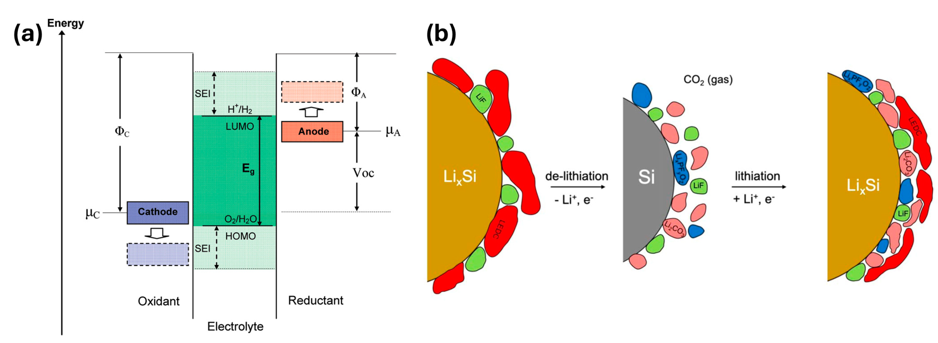
2.1. Reaction Mechanism of Si-Negative Electrode

Si is a negative electrode material that forms an alloy via an alloying reaction with lithium (Li) ions. During the lithiation process, Si metal accepts electrons and Li ions, becomes electrically neutral, and facilitates alloying. Conversely, during delithiation, Li ions are extracted from the alloy, reverting the material to its original Si metal state through dealloying.
xLi+ + xe + Si ↔ LixSi
Alloy-forming negative electrode materials can achieve significantly higher capacities than intercalation electrode materials, as they are not limited by the host atomic structure during reactions. In the Li–Si system, Li22Si5 is the Li-rich phase, containing substantially more Li than the fully lithiated graphite phase, LiC6. Thus, Si can achieve a theoretical maximum specific capacity of 4200 mAh g−1 during lithiation, whereas graphite reaches only 372 mAh g−1. Primarily, crystalline Si has been developed as an active material, undergoing electrochemical lithiation via a two-phase mechanism, likely owing to the high activation energy required to decompose the crystalline Si matrix [41,42,43,44]. During this process, Si reacts with Li, resulting in the formation of lithiated amorphous Si (LixSi). This LixSi phase is highly lithiated, containing approximately 3.4 ± 0.2 Li atoms per Si atom [45].
The Li storage mechanism in crystalline Si varies with temperature (Figure 1). At high temperatures, Si exhibits a step-shaped galvanostatic voltage profile during lithiation/delithiation, arising from Si and Li ions, sequentially forming four stable crystalline intermediate phases (intermediate equilibrium phases) [46]. These phases, with nominal compositions of Li12Si7, Li7Si3, Li13Si4, and Li22Si5, exhibit voltage plateaus at 0.332, 0.288, 0.157, and 0.044 V. Among these, the Li22Si5 phase demonstrates the highest theoretical capacity for Si electrodes at high temperatures, reaching up to 4200 mAh g−1 [47]. In contrast, at room temperature, Si displays a continuous upward- and downward-curved galvanostatic voltage profile during lithiation/delithiation [41,48]. Initially, crystalline Si undergoes a two-phase reaction, where a significant number of Li ions surround the Si, transforming it into lithiated amorphous Si (LixSi) rather than forming equilibrium phases. Subsequently, the reaction continues in an amorphous state. During this process, the initial crystalline structure of Si is disrupted and fragmented, leading to the formation of Si–Si single bonds and Si atoms. These fragments continuously integrate into amorphous Li15Si4, resulting in a relatively flat voltage plateau at approximately 0.1 V [44,49]. The lithiation process at room temperature involves electrochemical solid-state amorphization, which forms metastable amorphous LixSi phases instead of equilibrium intermetallic compounds [46]. Solid-state amorphization occurs because the formation of equilibrium phases is kinetically hindered, resulting in the formation of an amorphous phase with a lower Gibbs free energy than that of the reactants [41]. During the lithiation process, when the potential decreases by approximately 50 mV, the highly lithiated amorphous LixSi immediately converts to metastable crystalline Li15Si4. Therefore, at room temperature, each Si atom can accommodate approximately 3.75 Li ions, resulting in a theoretical capacity of 3580 mAh g−1 [50]. The metastable Li15Si4 phase, not observed to be a line compound, undergoes a reaction within this phase when the cell has an open-circuit potential, leading to a self-discharge mechanism [45]. This can potentially cause a capacity loss in batteries with Si-negative electrodes. Subsequently, the crystalline Li15Si4 phase returns to amorphous Si during delithiation, accompanied by volume contraction [51]. At room temperature, the discontinuous conduction pathways of Si, along with the residual Li15Si4 within the Si bulk phase, increase the irreversible capacity, thereby reducing the ICE.

2.2. SEI Formation of Si-Negative Electrode

During the initial lithiation of the negative electrode, as Li ions are incorporated into the active material, the potential of the negative electrode decreases below 1 V (vs. Li/Li+) toward the reference electrode (Li metal), approaching 0 V in the later stages of the process. In Figure 2a, the stability window of the electrolyte (Eg) is represented by the energy gap between the lowest unoccupied molecular orbital (LUMO) and the highest occupied molecular orbital (HOMO) [52]. If the electrochemical potential (μA) of the negative electrode exceeds the LUMO, the electrolyte is reduced until a passivation layer forms that prevents electron transfer to the LUMO. Typically, the organic electrolytes used in LIBs exhibit oxidation and reduction potentials around 4.7 V and 1.0 V vs. Li/Li+, respectively [53]. The working potential of Si electrodes, approximately 0.37 V vs. Li/Li+, falls below the stability window of the electrolyte [54]. This decrease in voltage prompts the organic electrolyte to undergo reductive decomposition on the surface of the negative electrode, owing to the reduction potential of the electrolyte exceeding that of Li. The interaction of the organic electrolyte with the active material results in the formation of an SEI layer on the negative electrode surface [52]. The composition and structure of the SEI layer on Si electrodes evolve into a more complex form with repeated cycling owing to inherent structural instability. In EC-based electrolytes, the initial SEI on Si electrodes predominantly comprises lithium ethylene dicarbonate (LEDC) and lithium fluoride (LiF), which are reduction products of the electrolyte [55]. During the lithiation/delithiation process, the extensive volume changes cause fractures in Si particles, increasing their surface area. This results in LEDC, the initial SEI component, evolving into a more complex SEI, which produces lithium carbonate (Li2CO3), lithium oxide (Li2O), CO2, and other by-products (Figure 2b). On the Si surface, predominantly oxidized to SiO2, reactions with Li yield by-products such as lithium silicate (LixSiOy) and Li2O [56]. Consequently, a substantial amount of lithium silicate accumulates on the Si surface, with the SEI layer progressively being composed of LEDC, Li2CO3, and LiF towards the outer regions [52,57,58,59,60]. To overcome the challenges with Si electrodes, which will be outlined in the following sections, a comprehensive understanding of surface reactions must be established in advance.

2.3. Challenges of Si-Negative Electrode

Si particles exhibit intrinsic properties that lead to unfavorable phenomena in Si-negative electrodes (Figure 3). This section provides a detailed discussion of the various challenges associated with Si, specifically addressing extreme volume change, unstable SEI, and low electrical conductivity.

2.3.1. Extreme Volume Change during (De)Lithiation

Commercially used graphite electrodes experience approximately 10–13% expansion during Li intercalation [63]. However, one unavoidable challenge with alloy-type electrode materials such as Si is the significant volume change during lithiation/delithiation, leading to decreased cycle stability. When fully lithiated, Si accommodates approximately 4.4 Li atoms per Si atom, resulting in a substantial volume expansion of approximately 420% (assuming that the final alloy composition is Li22Si5). As depicted in Figure 3, the repetitive large volume changes in the particles induce high internal stresses in the Si, leading to the cracking and pulverization of the Si particles. The fragmentation of Si particles causes the active material to lose electrical contact with the electrode components, including conduction agents, binders, conductive networks, and current collectors, resulting in self-isolation of the active material. Consequently, this loss of active material accelerates capacity fading and can lead to reduced rate capability and voltage degradation [3]. Therefore, ongoing research efforts focus on alleviating the volume expansion of Si particles during cycling to enhance cycle stability.

2.3.2. Unstable Solid–Electrolyte Interphase (SEI)

Significant volume changes in Si electrodes induce particle pulverization leading to repetitive growth and the formation of unstable SEI layers [4]. During cycling, the pulverization repeatedly exposes fresh Si surfaces to the electrolyte, causing the cracking, delamination, and regrowth of the SEI layers (Figure 3). As the SEI layer continues to grow excessively, it leads to ongoing decomposition and consumption of the electrolyte, resulting in a significant depletion of Li ions. In EC-based electrolytes, SEI components such as LEDC, Li2CO3, Li2O, and CO2, which predominantly dissolve in the electrolyte or exist as gases, increase the porosity of the SEI layer. This enhanced porosity facilitates further electrolyte reduction and forms a thicker SEI. A thick SEI layer impedes both electrical conduction pathways and the diffusion of Li ions into the electrode, significantly hindering electrochemical reactions and resulting in reduced Coulombic efficiency (CE) and reversible capacity. Consequently, for optimal electrochemical performance, the SEI layer must effectively prevent direct contact between the electrolyte and the active material to avoid further electrolyte decomposition [5]. Especially for Si, the SEI requires robustness to withstand the substantial volume expansion of Si particles during cycling, thereby adapting flexibly to changes in particle morphology and ensuring stability through extended cycling periods.

2.3.3. Low Intrinsic Electrical Conductivity

Si, a semiconductor, exhibits low intrinsic electrical conductivity, approximately 1 × 10⁻³ S cm−1. Following lithiation, this conductivity may increase to approximately 1 × 10² S cm−1; however, such enhancement is inadequate for efficient electron and Li-ion transport within the Si matrix, thus hindering overall battery performance [6]. Additionally, Si demonstrates a low Li diffusion coefficient, ranging from 10−14 to 10−13 cm2 s−1, which further restricts Li-ion mobility [7,8,9]. These intrinsic limitations, including low electrical conductivity and sluggish Li diffusion, severely limit the utilization of its full capacity and impact its rate capabilities and overall efficiencies [64,65,66]. Therefore, the development of innovative strategies to augment the conductivity and mobility of Li ions is crucial for improving battery performance.

3. Surface-Coating Strategies for Improvement of Si Performance

To address the challenges associated with Si electrodes, extensive research has been conducted. Nanotechnologies, in particular, have proven to be an effective strategy for enhancing cycle life and rate capabilities [16,17,18,19,20,21,22]. Nanomaterials, compared to bulk materials, exhibit markedly different behaviors due to their unique properties: (i) They can buffer volume changes during lithiation/delithiation, enhancing cycle stability and maintaining a high capacity. (ii) Their increased surface area shortens electron transport and Li-ion diffusion distances, reducing polarization and improving rate capabilities [67]. However, Si nanoparticles (SiNPs) still experience fragmentation during cycling, owing to the extreme volume expansion of Si (>300%), even as particle expansion diminishes. This results in unstable SEI growth and reduced cycle stability. The large surface areas cause uncontrolled reactions and thermal runaway, raising serious safety concerns. Additionally, their intrinsic low electrical and ionic conductivity lead to low ICE [68,69]. To address these limitations of SiNPs, considerable research has focused on the development of Si nanocomposites with core–shell, yolk–shell, porous, and hollow structures. Surface coating has proven to be highly effective in preventing direct contact between Si and the electrolyte. These coatings enhance electrochemical stability, modify the properties of Si, and facilitate the formation of a thin, stable SEI film. They also facilitate rapid Li-ion transport and can be either robust or flexible, thereby mitigating the mechanical stress experienced by SiNPs [70]. The introduction of coating layers into Si nanostructures is increasingly being recognized as a promising strategy for enhancing both tap density and cycling stability [32,33,34,36,37,38,40,71,72].

3.1. Common Coating Methods

To enhance the efficiency of next-generation LIBs, research on various surface-coating strategies has intensified. This section addresses the six most commonly employed coating methods: high-energy ball milling, hydrothermal synthesis, chemical vapor deposition, electrospinning, the sol–gel method, and spray drying. A schematic of these common coating methods is provided in Figure 4. Each coating method exhibits distinct advantages and limitations; thus, combining two or more methods is a common practice to optimize outcomes. When applying surface-coating processes to SiNPs, considering the high performance as well as cost, efficiency, and complexity of the processing methods is imperative. The advantages and disadvantages of each surface-coating method are briefly described in Table 1.
Table 1. Comparison of the advantages and disadvantages of different coating methods [73]. Reused with permission from Ref. [73]. Copyright © 2021 WILEY.
Coating MethodAdvantagesDisadvantages
High-energy ball millingLow cost, easy operation, simple equipment, suitable for industrial productionNon-uniform coating layer that detaches easily, contamination of products despite adequate protection
HydrothermalLow cost, low process temperature, minimal pollution, simple equipment, suitable for large-scale preparation and industrial productionExtended processing time, low purity, non-uniform coating layer thickness, partial oxidation of Si particles, frequent necessity for subsequent treatments
CVDHigh uniformity (quality), controllable coating thickness, dense coating layerHigh-temperature requirements, high costs, complex processing steps, limitations on materials that can be coated, variable yields, expensive equipment
ElectrospinningCapable of preparing complex hierarchical and free-standing structures, high uniformityLimited geometrical freedom, non-scalable due to low production rates, potential safety hazards due to high voltage
Sol–gelHigh processing feasibility, excellent homogeneity, cost-effectivenessSignificant shrinkage during processing, presence of residual porosity or hydroxyl groups, long processing times
Spray dryingLow cost, ease of operation, suitable for large-scale production in continuous modeRestrictions on materials that can be coated, thick coating layers, large equipment size, complex equipment requirements, high power consumption, low energy efficiency
Figure 4. Scheme of fundamental setup and procedures of common coating methods. (a) HEBM [74]. Reprinted with permission from Ref. [74]. Copyright © 2022 MDPI. (b) Hydrothermal method. (c) CVD. (d) Electrospinning [75]. Reprinted with permission from Ref. [75]. Copyright © 2021 Elsevier. (e) Sol–gel. (f) Spray drying [76]. Reprinted with permission from Ref. [76]. Copyright © 2018 MDPI.
Batteries 10 00327 g004

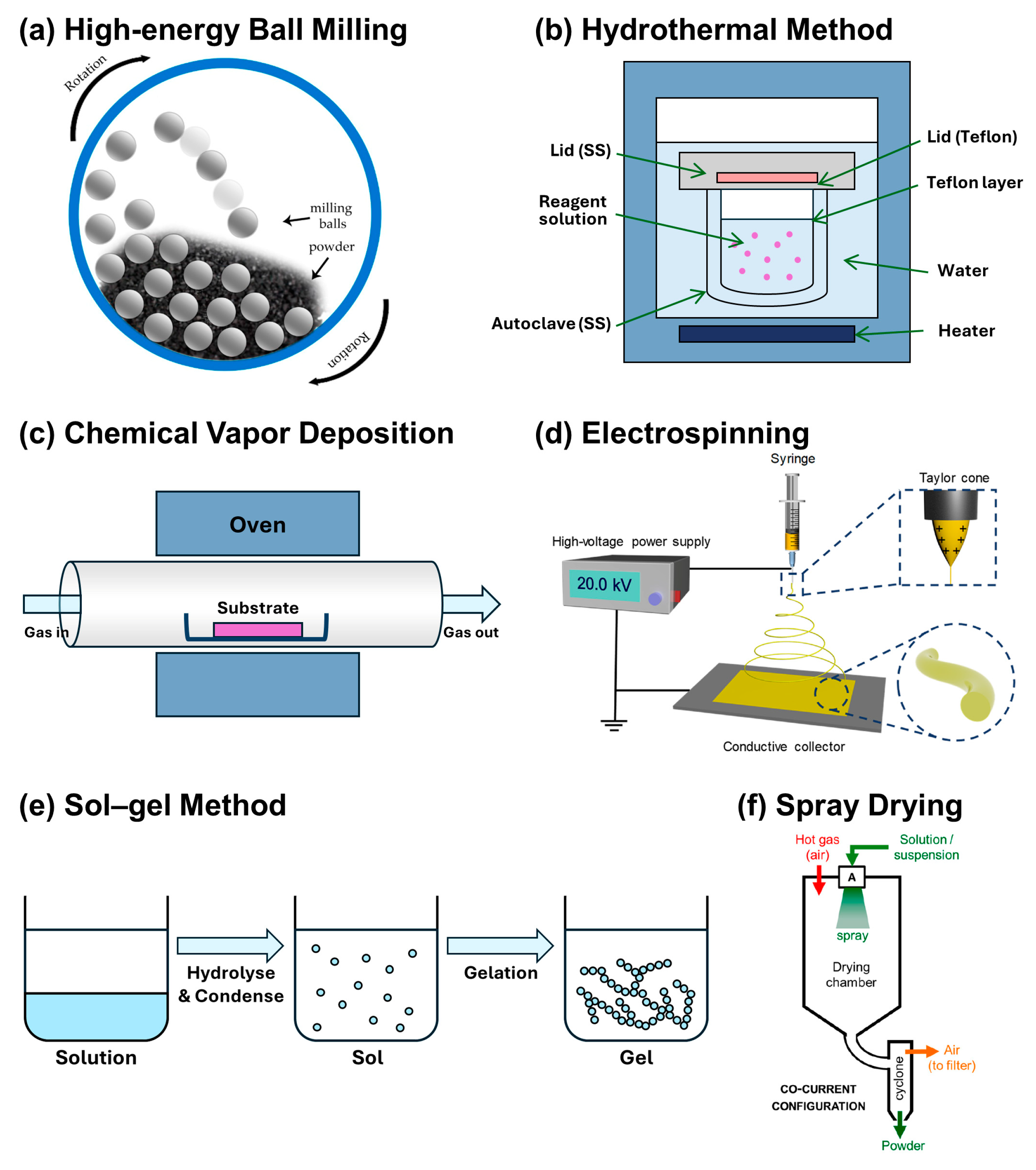
3.1.1. High-Energy Ball Milling (HEBM)

HEBM represents an efficient method for nanoparticle production. The HEBM process is depicted in Figure 4a [74]. This method operates on the principle of mechanical alloying, where repeated fracturing and cold welding of powder particles occur. The rotation of the milling chamber generates significant impact forces and friction between balls and chamber walls, leading to the deformation and fracture of raw materials [77,78,79]. These interactions lead to surface modifications that result in the synthesis of nanostructured materials with enhanced chemical properties [80]. Owing to its simplicity, cost-effectiveness, and scalability, HEBM has been predominantly utilized for the surface coating of Si-based active materials [81]. Fan et al. [24] synthesized nano-sized Si/C core-shell structures by combining HEBM with subsequent carbonization using polyperinaphthalene (PPN) as the carbon precursor. The resulting samples exhibited an initial capacity of 1512.6 mAh g−1 and maintained a capacity retention of 74.2% after 500 cycles. This improvement is attributed to the modification of the Si surface by ball milling, which allows for the formation of covalent bonds between the carbon shell and Si surface, thereby enhancing structural stability. However, this method introduces impurities, presents challenges in particle size control depending on milling duration, and poses limitations on feasible chemical combinations, complicating its application in large-scale composite manufacturing [77].

3.1.2. Hydrothermal Method

Hydrothermal synthesis, a widely employed method for producing various metal oxide nanostructured materials, primarily facilitates the synthesis of crystals and ceramic powders. A fundamental setup for the hydrothermal method is schematically shown in Figure 4b. This process involves chemical reactions within a mixed precursor solution under conditions exceeding the boiling point of water. An autoclave reactor is typically used to generate necessary high-temperature and high-pressure environments, utilizing water or organic solvents as the reaction medium to fabricate nanomaterials. The resultant slurry is cooled, filtered, washed, and dried to obtain the synthesized powder. For carbon coatings, the carbon source must undergo additional heat treatment at elevated temperatures of 400–750 °C in a N2 or Ar atmosphere to achieve carbonization. Shao et al. [25] employed glucose as a carbon source to synthesize nanostructured Si/porous carbon spherical composites (N-SPC) using a hydrothermal process combined with a soft template method. The porous structure facilitated SEI layer formation and enhanced the mobility of electrons and Li ions. Consequently, the N-SPC composites exhibited high cycling stability with an 85% capacity retention and 1607 mAh g⁻1 after 100 cycles. Additionally, they demonstrated excellent rate capability, delivering 1050 mAh g⁻1 even at a high current density of 10 A g⁻1. The temperature of the water is a critical parameter, as it influences the reaction rate, ionization degree, particle size, and crystalline structure of the powder. Furthermore, the particle size, morphology, and chemical composition can be controlled by adjusting the concentration of the reactants and the reaction duration [82]. During the process, heated water facilitates particle diffusion, leading to relatively rapid crystal growth. This method is simple, cost-effective, and particularly effective at preserving intrinsic material properties. It is suitable for growing large, high-quality crystals with controlled composition. However, it may yield non-uniform thickness of coating layers and partial oxidation of Si particles, and it may present challenges in monitoring crystal growth.

3.1.3. Chemical Vapor Deposition (CVD)

CVD is a widely used technique to create thin films and coatings by depositing material from a vapor phase onto a substrate, where gaseous precursors are decomposed through chemical reactions. The CVD process is depicted in Figure 4c. This process involves transporting gaseous reactants into a tube furnace, where they undergo chemical reactions and are subsequently deposited onto the substrate surface. Wu et al. [26] synthesized double-walled Si–SiOx nanotubes (DWSiNTs) by coating carbon fibers with Si via CVD, followed by annealing in an air atmosphere to selectively remove the inner carbon template. The SiOx layer of the continuous Si tube provided mechanical robustness, mitigating volume expansion as Si expanded inward. Consequently, DWSiNTs maintained stable capacity over a long-term cycle of up to 6000 cycles. Through this method, high-quality and high-purity films can be synthesized, and the thickness of the coating layer can also be controlled. In producing Si-based electrode materials, CVD is utilized to enhance the synergy between the coating material and the surface of SiNPs. Additionally, the process is relatively convenient and easily controlled due to its mechanized nature. However, CVD is associated with high costs, the necessity for high-temperature conditions, and the complexity of processing steps. Additionally, other gas-phase deposition methods, including atomic layer deposition (ALD) [83,84,85], physical vapor deposition (PVD) [86,87,88,89], pulsed laser deposition (PLD) [87,90], and supercritical carbon dioxide fluid method (SCCO2) [91], are also being investigated for coating Si.

3.1.4. Electrospinning

Electrospinning is an effective method for synthesizing nanofibers from polymer solutions and composites. A fundamental setup for electrospinning to produce nanofibers is schematically shown in Figure 4d [75]. This process uses kilovolt-level electrostatic voltages on polymer solutions, creating a Taylor cone, where electric fields cause charged droplets to overcome surface tension and create polymer nanofibers [92,93]. Among the various parameters, adjusting the precursor solution composition is the most convenient method for controlling the produced fibers. Its economic viability and simplicity make it suitable for preparing complex hierarchical and free-standing structures. In the LiB industry, electrospinning is employed to synthesize carbon nanofibers (CNFs) that are subsequently coated onto SiNPs to enhance electrochemical performance. Zhang’s group [27] utilized polyacrylonitrile (PAN) as both a spinning medium and carbon precursor to synthesize Si/C composite nanofibers through electrospinning and subsequent carbonization. Electrodes derived from 15 wt.% Si/PAN precursors carbonized at 800 °C demonstrated a high capacity of 962 mAh g⁻1 and stable cycling performance with 67.3% capacity retention after 50 cycles. This enhanced performance is due to the high surface area of CNFs, excellent electrical conductivity, and continuous carrier transport channels, which effectively buffer the volume expansion of Si during lithiation and facilitate rapid carrier transport. Nonetheless, this method faces challenges such as low yield and potential safety risks associated with high voltage.

3.1.5. Sol–Gel Method

The sol–gel method is a low-temperature wet synthesis method often developed for the synthesizing metal oxides or inorganic materials such as ceramics or glasses. The procedures in the sol–gel method are depicted in Figure 4e. The sol–gel method, originally developed for synthesizing inorganic materials such as ceramics and glasses, is straightforward and scalable. The process involves creating a colloidal suspension (sol) and inducing gelation to form a network structure (gel), which is then dried and heat-treated. Within the LiB industry, this technique is applied extensively to produce SiO2 or carbon layers that coat the surfaces of SiNPs. Specifically, SiO2 is a sacrificial layer strategically etched to create voids within Si nanostructures. Liu et al. [94] synthesized a 3D N-doped carbon-coated hierarchically porous Si (hp-Si@NC) composite using a sol–gel process accompanied by phase separation, followed by a magnesiothermic reduction and a polydopamine pyrolysis. The hp-Si@NC composite demonstrates outstanding electrochemical performance due to its unique porosity and N-doped carbon layer. It exhibits initial discharge and charge capacities of 1077 and 723 mAh g⁻1, respectively, at a current density of 0.2 A g⁻1. The CE improves from 67.1% in the first cycle to 99% by the 100th cycle, indicating superior rate performance. Nonetheless, this method faces challenges such as significant shrinkage during processing, residual porosity (or hydroxyl groups), and prolonged processing times.

3.1.6. Spray Drying

Spray drying, a primary technique for the mass synthesis of powdered materials, involves dispersing a slurry or liquid into fine particles through mechanical action, subsequently drying into spherical powder particles using hot air. A fundamental setup for the hydrothermal method is schematically shown in Figure 4f [76]. Key parameters include the feed rate, atomization pressure, and drying temperature, which affect the particle size and morphology. Pan et al. [29] employed a spray-drying method followed by a calcination process to fabricate micro-sized Si@carbon@graphene spherical composites (Si@C@RGO). This structure, where Si is encapsulated with carbon and graphene, significantly enhances the electrical conductivity of the composite and accommodates the substantial volume changes of Si during cycling. As a result, the Si@C@RGO electrodes exhibited excellent electrochemical performance, achieving a capacity of 1599 mAh g⁻1 at 100 mA g⁻1, a capacity retention of 94.9% at 200 mA g⁻1, and a high reversible capacity of 951 mAh g⁻1 at 2000 mA g⁻1. Spray drying is highly scalable and relatively high-yield, making it increasingly popular for producing Si/C materials. Nevertheless, the limitations of this method include constraints on suitable coating materials and the potential for producing overly thick coating layers.

3.2. Coating Materials

Coating materials should ensure the effective prevention of direct exposure of Si particle surfaces to the electrolyte. Consequently, these materials should inherently demonstrate high mechanical stability to accommodate the volumetric expansion of Si during cycling, while also exhibiting electrochemical inertness to inhibit undesirable side reactions with Li-ions and the electrolyte. In addition, to compensate for the low electrical conductivity of Si, the coating material must also possess high electrical conductivity. Coating materials for nanostructured Si encompass a diverse range of substances, including carbon [28,30,32,33,34,35,36,95], silicon oxides [38,39,40], metals [31,37,96,97], metal oxides [71,72,84], and polymers [98,99,100,101]. In this review, we categorize the coating materials based on their chemical composition and physical properties into four main groups: carbonaceous materials, Si oxides, metals, and metal oxides. The advantages and disadvantages of each surface-coating material are briefly described in Table 2.

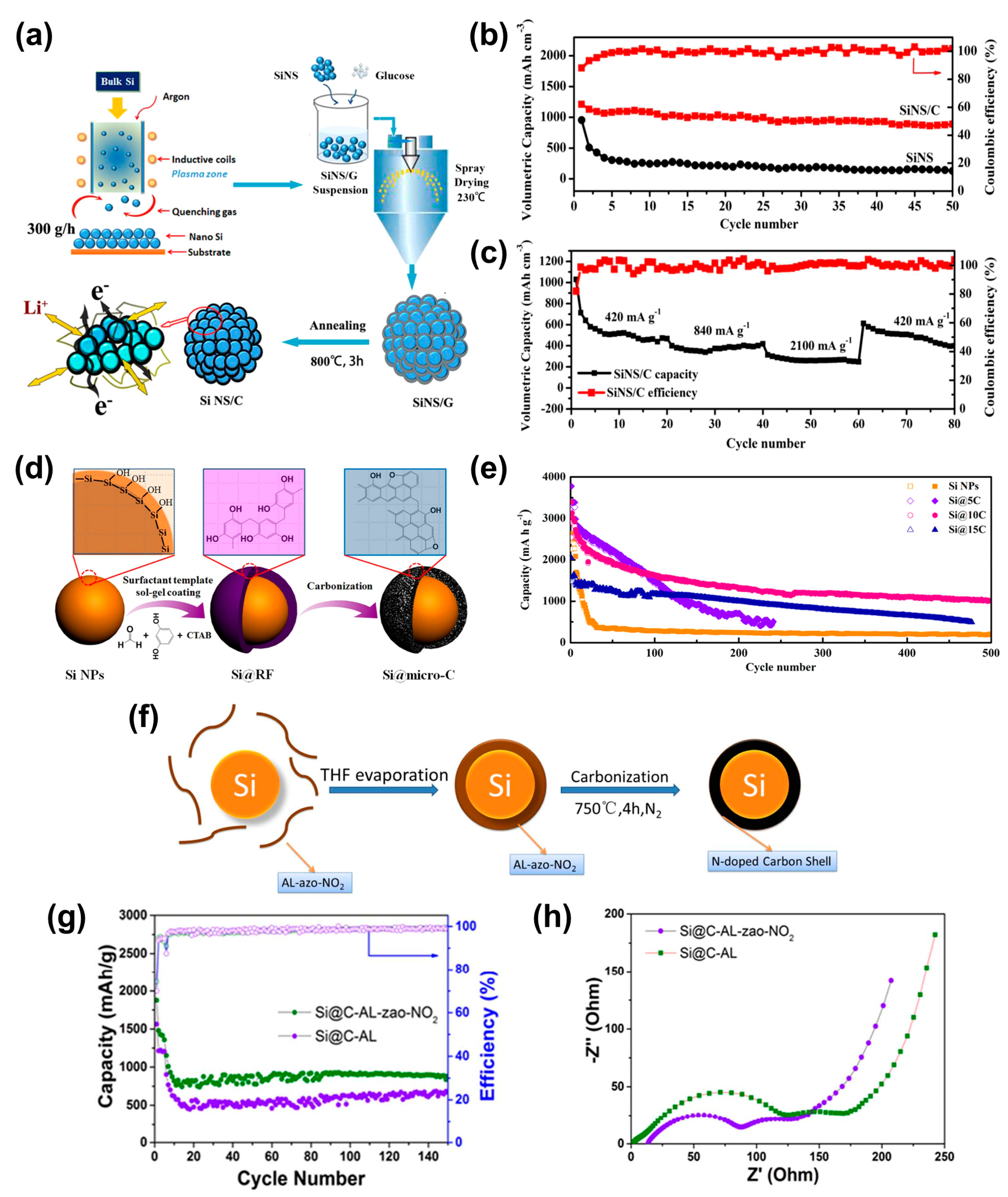
3.2.1. Carbonaceous Materials

Carbon-coated Si-based negative electrodes have been a focal point since their proposal in the early 21st century [102]. Owing to their numerous advantages, carbonaceous materials are the prevalent choice for Si coatings. Carbon exhibits excellent electrical conductivity, which enhances electrical contact between Si particles and other electrode components, reducing electrode polarization. Additionally, carbon coatings stabilize the negative electrode–electrolyte interface, inhibiting excessive SEI growth and enhancing CE. The minimal volume change in carbon during cycling (approximately 10% for graphite) effectively buffers the volume expansion of Si [63,103]. These benefits of carbon coating have established structures such as core–shell, yolk–shell, and porous configurations as promising strategies for embedding Si particles within a uniform carbon shell.
Core–shell structures consist of a sturdy inner core surrounded by one or more diverse material layers (shells). The outer carbon shell protects the Si core from environmental fluctuations, restricts volume expansion, and preserves structural integrity, thereby preventing the aggregation of the core into larger particles. Such architectures frequently exhibit enhanced chemical and physical properties relative to that of monolithic materials [104]. Hou et al. [32] synthesized a Si/C micro-/nanocomposite (SiNS/C) with a 3D plum pudding-like morphology through radiofrequency induction thermal plasma processing and subsequent spray drying using glucose as the carbon source (Figure 5a). This Si/C electrode demonstrated a high ICE of 88%, a high volumetric capacity of ~1244 mAh cm−3, and a stable rate performance compared with that of pristine SiNPs (Figure 5b,c). The enhanced electrochemical performance is attributed to the 3D structure, which accommodates volume changes, facilitates Li-ion transport, and enhances conductivity and stability through the carbon matrix. Luo et al. [33] investigated the impact of carbon-coating thickness on the long-term cycling performance of core–shell structures prepared by the sol–gel method, coating SiNPs with a phenolic-resin-based microporous carbon layer (Figure 5d). An analysis of samples with carbon shell thicknesses of 5, 10, and 15 nm showed that the 10 nm carbon shell displayed the highest capacity of 1006 mAh g−1 and a CE of 99.5% after 500 cycles at 500 mA g−1 (Figure 5e). A 10 nm carbon shell is optimal as it effectively alleviates internal stress caused by volume changes in SiNPs during cycling while facilitating fast Li-ion transport and stable SEI film formation. Precise engineering of the carbon shell thickness is crucial for balancing capacity and structural stability. Du et al. [34] synthesized carbon-coated SiNPs using alkali lignin (AL) or an AL-derived azo polymer (AL-azo-NO2) as carbon precursors. The Si@C composites were prepared by evaporating the THF solvent from the dispersion solutions of the SiNP/carbon precursors, followed by carbonization in a nitrogen atmosphere (Figure 5f). The AL-azo-NO2 precursor can synthesize an N-doped carbon shell, exhibiting superior electrochemical performance compared to that of AL-derived carbon shell. Si@C-AL-azo-NO2 demonstrated a high reversible capacity of 882 mAh g−1 at 200 mA g−1 with a high CE of 99% (Figure 5g) and a lower Rct value due to its N-doped carbon shell (Figure 5h). These results confirm that N-doped carbon significantly enhances electrical conductivity and improve electrochemical performance relative to undoped Si@C materials. However, during lithiation/delithiation, the volumetric expansion of the core SiNPs within Si/C core–shell structures can compromise the structural integrity of the carbon shell, potentially leading to the exposure of the Si core. Therefore, novel structures aimed at mitigating this issue have been a subject of discussion.
In contrast to the core–shell structure, the Si/C yolk–shell structure, where the Si core and carbon shell experience indirect contact, is characterized by a hybrid design with a hollow carbon shell surrounding a mobile Si core in an empty space. This void effectively buffers the volume expansion of the Si core during cycling, outperforming the core–shell structure. Consequently, this design is highly beneficial for maintaining the integrity of the Si core by shielding it from exposure to the external environment. Zhang et al. [28] employed a one-pot sol–gel approach, utilizing resorcinol–formaldehyde (RF) and tetraethyl orthosilicate (TEOS) as precursors, to synthesize Si/C yolk–shell composites. This method involved etching the SiO2 layer with a 15% HF solution (Figure 6a). In this configuration, a ~60 nm void between the Si core and the carbon shell effectively mitigates the volume expansion of Si particles, thereby enhancing cycle stability. As a result, the Si@HC-1 samples exhibited a high charge capacity of 1807.4 mAh g⁻1. Furthermore, at 1 A g⁻1, these samples maintained a reversible capacity of 500 mAh g⁻1 even after 2000 cycles (Figure 6b). This verifies that the carbon shell serves a dual function: enhancing the electrical conductivity of Si and acting as a protective barrier during cycling. This prevents electrolyte decomposition, thereby ensuring stable maintenance of the SEI. Similar research has been conducted on dual yolk–shell structures. Yang et al. [30] reported the first successful synthesis of a dual yolk–shell structure (Si/void/SiO2/void/C). This novel structure was fabricated by selectively etching SiO2 in a Si/SiO2/C configuration using HF solution (Figure 6c). In the dual yolk–shell structure, the carbon layer enhances conductivity, and the SiO2 layer provides mechanical strength. The two inner voids effectively accommodate the volume expansion of Si during lithiation. Consequently, the Si/C core–shell structure exhibited a sharp capacity decline within the first 10 cycles under identical experimental conditions. Conversely, the dual yolk–shell structure demonstrated outstanding electrochemical performance, maintaining a stable and high specific capacity of 956 mA h g−1 and a capacity retention rate of 83% at a current density of 0.46 A g−1 even after 430 cycles (Figure 6d). Additionally, the Si/void/SiO2/void/C composite demonstrated excellent rate capability (Figure 6e).
The porous structure, similar to that of the yolk–shell structure, integrates voids within its framework to mitigate the volumetric expansion of Si. The yolk–shell structure establishes a gap between the Si and carbon shells to introduce voids, whereas the porous structure incorporates voids directly within the Si matrix to mitigate volumetric expansion; that is, a structure in which porous Si is coated with carbon. Consequently, as porosity in Si increases, the potential to mitigate volumetric expansion also increases. However, this increased porosity can significantly diminish the compressive strength of the particles, leading to a decline in structural integrity. Furthermore, increased porosity augments the specific surface area of the Si-negative electrode, facilitating rapid Li-ion diffusion, which enhances the reactivity of the negative electrode and, consequently, its electrochemical performance. Nonetheless, such enhanced reactivity may promote side reactions at the electrode–electrolyte interface, emphasizing the necessity for a carbon-coated layer to prevent direct contact between the electrolyte and electrode surface and to stabilize the interface. Therefore, the meticulous design of the carbon-coated porous Si structure is pivotal for achieving high ICE and sustained cycle stability. An et al. [35] synthesized ant-nest-like microscale porous Si (AMPSi) using a scalable top-down technique, creating a structure of three-dimensionally interconnected Si nanoligaments and bicontinuous nanopores (Figure 7a). This porous configuration accommodates volume expansion during cycling, effectively mitigating particle-level outward expansion (Figure 7b). The carbon-coated AMPSi-negative electrode exhibited outstanding electrochemical performance, with a specific capacity of 1271 mAh g−1 and 90% capacity retention after 1000 cycles at 2100 mA g−1 (Figure 7c). Additionally, the electrode showed a substantial reduction in volume expansion to 17.8% during cycling, relative to the 300% expansion observed in pure Si electrodes. To examine the impact of porosity within the porous structure on electrochemical performance, Men et al. [36] synthesized hierarchically structured Si/C composite microspheres using a spray-drying-assisted magnesiothermic reduction method (Figure 7d). During this process, a carbon precursor, gelatin, was deposited onto the SiO2 nanospheres; subsequent magnesiothermic reduction carbonized the gelatin, resulting in porous SiNPs encapsulated in a carbon shell. TEM analysis confirmed successful carbon coating on the SiNPs in all three samples (Si/C-X, X = 1, 2, 3), with increasing carbon content and density and decreasing porosity as X increased. During the galvanostatic cycling evaluation (Figure 7e) at a current density of 200 mA g−1, Si/C-2 maintained an excellent reversible capacity of 523 mAh g−1 and a CE above 99% even after 300 cycles. Si/C-2 exhibited superior rate capability (Figure 7f), attributed to its optimal porous structure, which mitigates volume expansion during lithiation/delithiation, and the appropriate thickness of the carbon coating, which enhances the stability and conductivity of the electrode material, facilitating efficient electrochemical reactions even under high-rate conditions. Therefore, the rational design of porous structures with optimal void spaces and density is paramount for Si/C composite negative electrodes to achieve high energy density, exceptional ICE, and extended cycling stability.

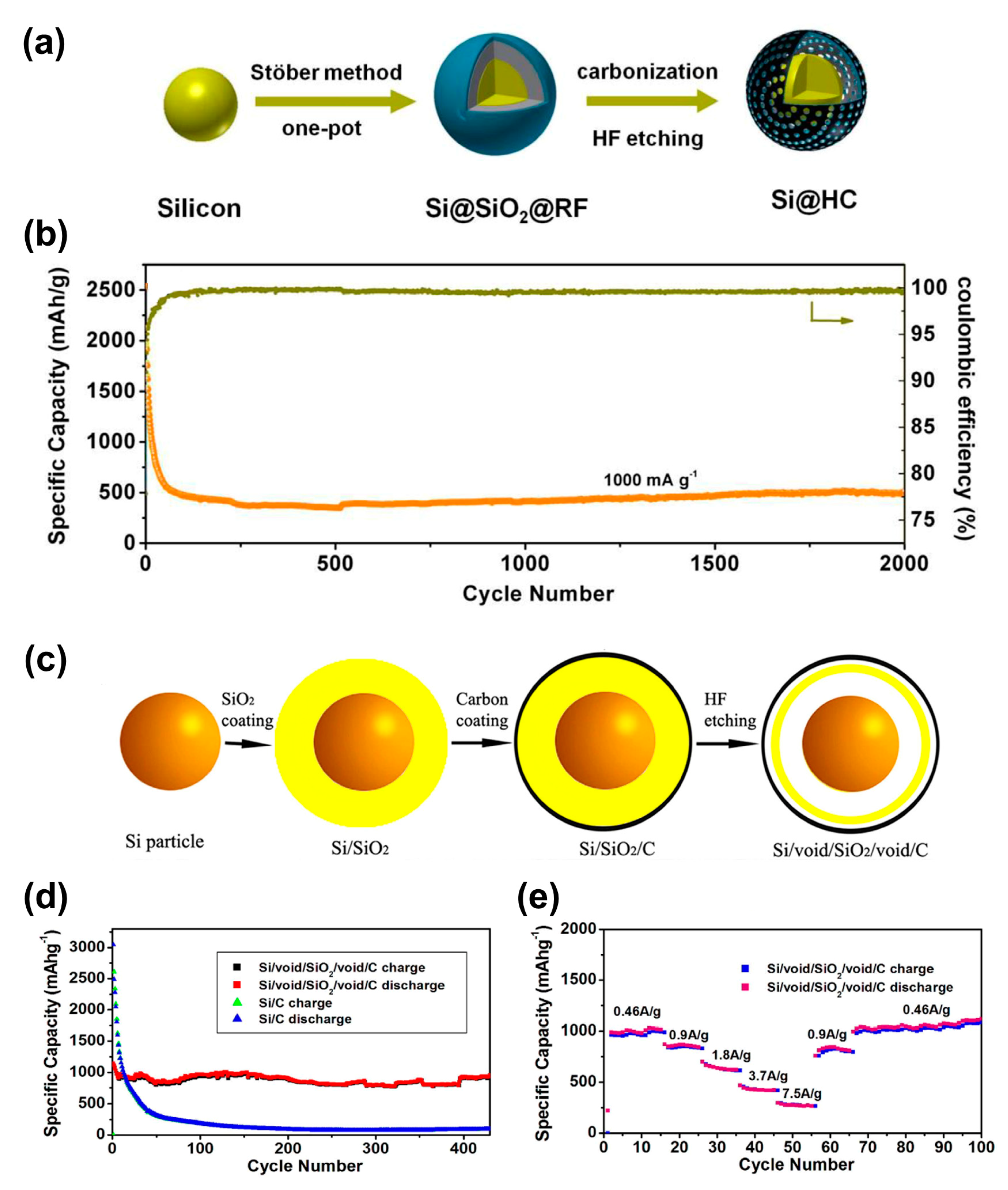
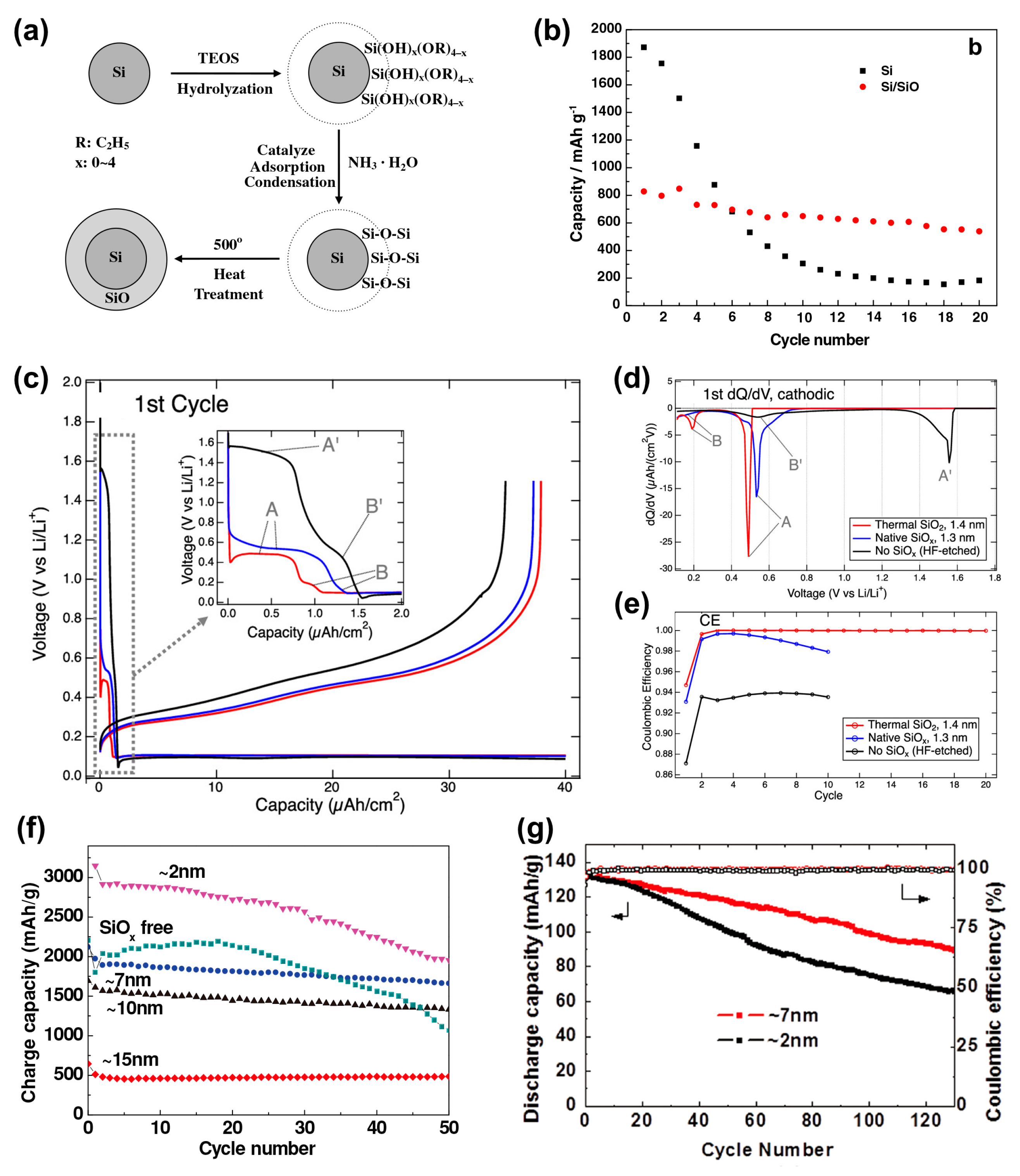
3.2.2. Si Oxides (SiOx)
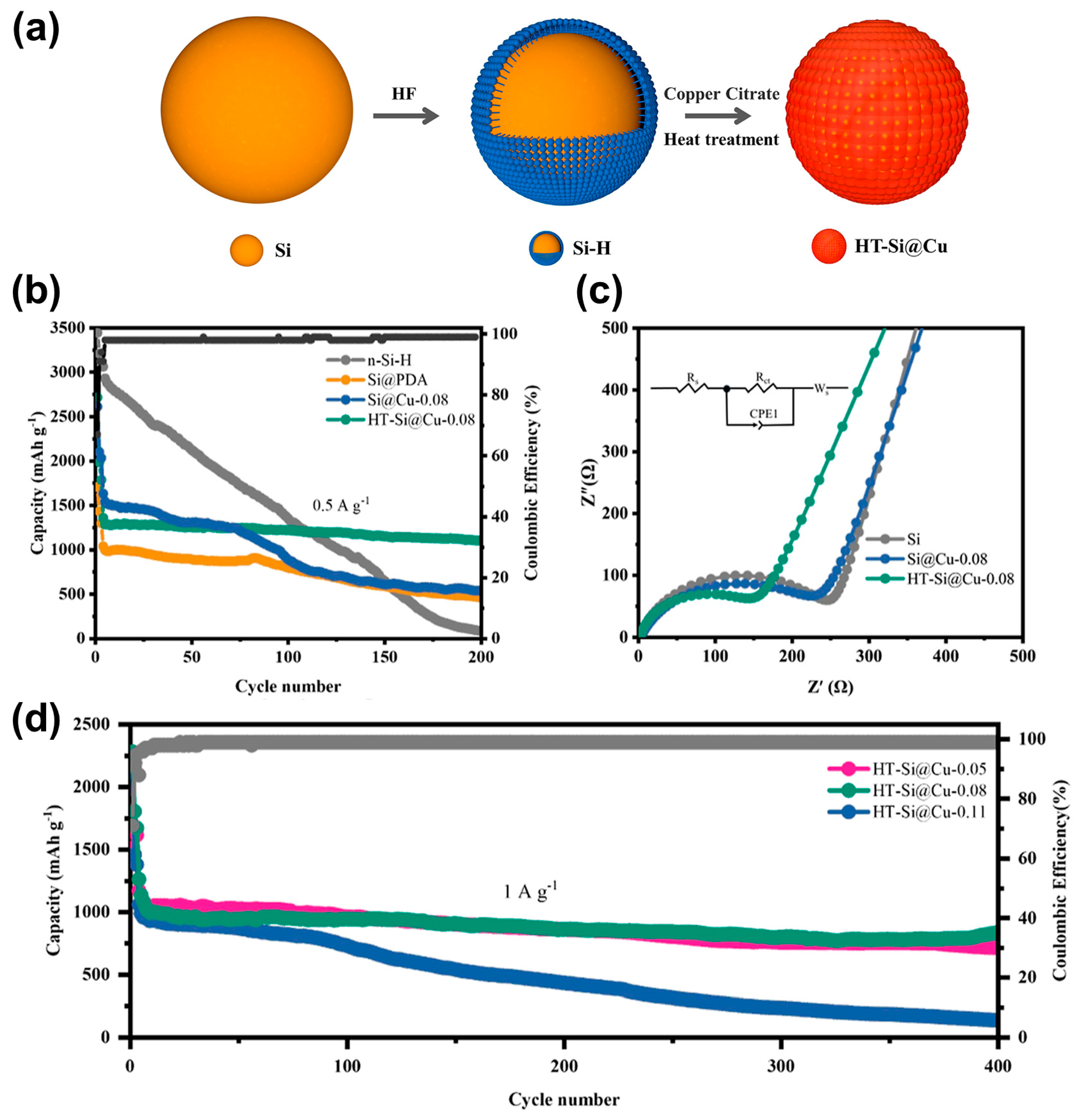
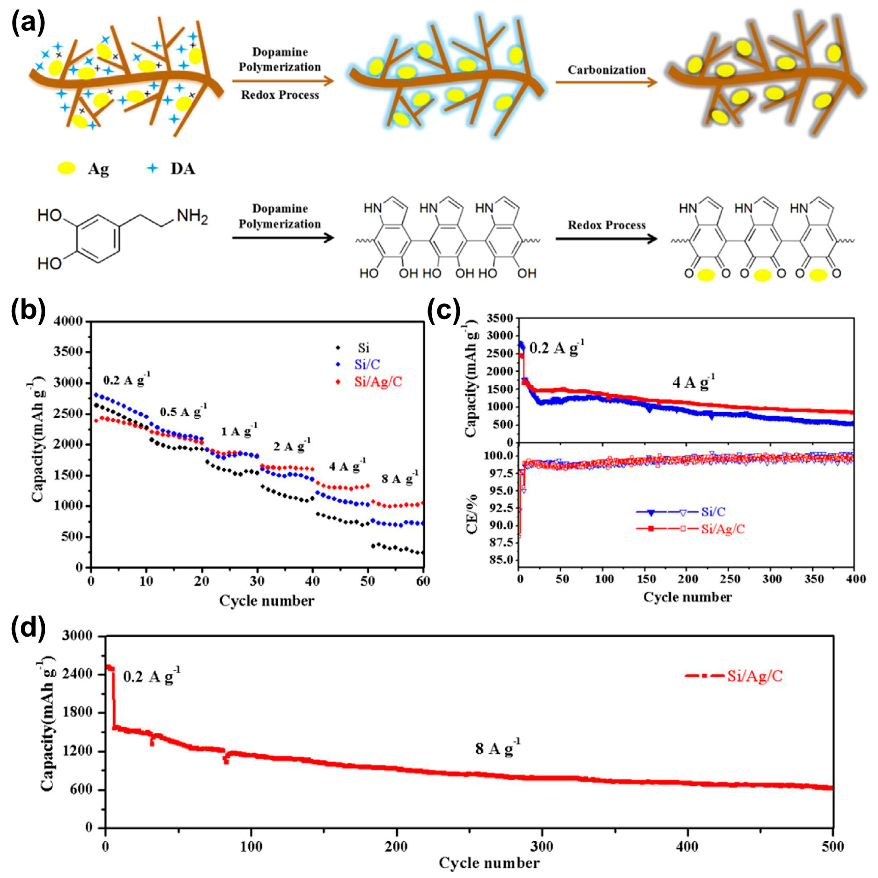
Si powder typically exhibits a surface covered with a native oxide layer (amorphous SiOx) with hydroxyl groups present at its terminations. Trace amounts of water and oxygen inevitably lead to the formation of an insulating SiOx layer. Density functional theory has demonstrated the following characteristics for this SiOx layer: SiOx exhibits much lower volumetric expansion than that of Si (approximately 160% during lithiation/delithiation), attributed to the significantly higher Si–O bonding energy compared with that of Si–Si bonding energy. During lithiation, SiOx acts as a barrier that blocks electrical conduction, leading to its transformation into lithium oxide (Li2O) and lithium silicate (Li4SiO4). These compounds serve as a matrix to buffer volume expansion in subsequent cycles. Consequently, the SiOx layer contributes substantially to structural stability during cycling, facilitating the formation of a stable SEI film and thereby enhancing cycling stability. Zhang et al. [38] synthesized a core–shell-structured Si/SiO nanocomposite using a sol–gel method, followed by additional heat treatment. Tetraethyl orthosilicate (TEOS) served as the SiO precursor (Figure 8a). The SiO coating layer acted as a barrier to prevent the aggregation of SiNPs during cycling. Additionally, it functioned as a buffer by forming Li4SiO4, which mitigates the volume expansion of the SiNPs and alleviates the destruction of the Si crystalline structure. The core–shell Si/SiO nanocomposite demonstrated superior Li insertion/extraction reversibility, higher CE, and better capacity retention than that of SiNPs (Figure 8b). The formation of SEI varied significantly with the surface of Si. Schnable et al. [39] conducted experiments on three types of Si wafers: a SiOx-free surface, native SiOx, and thermally grown SiO2 coatings (Figure 8c–e). The SiOx-free surface exhibited the lowest CE (<94%), the thickest SEI, and the highest overpotential for lithiation. Conversely, the SiOx surfaces demonstrated a high CE (>99%) after the second cycle, with a thinner and more stable SEI and a lower overpotential for lithiation. SiOx lowers the onset potential for electrolyte reduction and produces an SEI with fewer P–F species. However, the native SiOx surface exhibited a decay in the CE after the fifth cycle, which was associated with the resurgence of electrolyte reduction. Therefore, it was concluded that the thermally grown SiO2-coated surface minimizes side reactions and maintains the most stable SEI, ensuring efficient cycling. Sim et al. [40] investigated the optimal thickness of the SiO2 coating layer by evaluating the electrochemical performance of core@shell bulk@nanowire Si-negative electrodes with various SiO2 coating thicknesses. They observed that excessively thick native SiO2 coatings (10 and 15 nm) hindered the full lithiation of the electrode, resulting in decreased CE and specific capacity (Figure 8f). Owing to the low conductivity of the amorphous SiO2 shell, the coating must be sufficiently thin to allow for Li-ion insertion/extraction. However, excessively thin SiO2 layers (2 nm) failed to effectively buffer the volume expansion of the SiNPs. A SiO2 coating thickness of 7 nm significantly improved the electrochemical performance, including specific capacity, CE, and capacity retention, while effectively mitigating volume expansion (Figure 8g). Recently, Si carbide and nitride coatings, including Si oxycarbide (SiOC) [91,105,106,107] and Si nitride (SiNx) [108,109,110], have also been researched as coating materials to further enhance the performance of Si electrodes.

3.2.3. Metals

Owing to their higher electrical conductivity and mechanical strength compared with that of carbon materials, metals are being explored for coating Si surfaces. The selection of metals for coating materials must meet the conditions under which they facilitate the transport of Li ions through Si while remaining inert toward Li and electrolytes. Metal coating materials such as Cu, Ag, Ni, Co, and Fe have been employed for this purpose, with particular emphasis on the extensive research involving Cu and Ag.
Cu is a highly suitable coating material for mitigating the severe volume expansion and low electrical conductivity of Si during cycling. Its excellent electrical conductivity effectively enhances the electrochemical performance of SiNPs. Moreover, Cu remains electrochemically inert in the presence of Li ions, thereby mechanically stabilizing the SiNPs throughout cycling. Kwon et al. [37] synthesized Cu-deposited mesoporous SiNPs (mp-Si@Cu) via magnesiothermic reduction and electroless deposition. The mp-Si@Cu nanocomposite exhibited high ICE, long-term cycle stability, a high capacity of 1569 mAh g−1 after 200 cycles at a current density of 1000 mA g−1, and superior rate capability compared with that of mp-Si and mp-Si@C. The superior electrochemical performance of mesoporous Si@Cu is attributed to the deposition of Cu onto the Si surface, which enhances the electrical conductivity, increases Li+ ion mobility, and improves the structural stability, restricting the aggregation and pulverization of Si. Xu et al. [96] investigated a novel coating method through in situ solution chemical deposition and subsequent heat treatment, which successfully coated a high-strength Cu-based metal shell onto SiNPs (formation of HT-Si@Cu). The treatment of SiNPs with dilute HF acid generates reactive hydrogenated Si (n-Si-H) on the surface, followed by the addition of copper citrate, and results in the immediate reduction of Cu2+ ions and the formation of a Si@Cu composite. Additionally, heat treatment in an Ar/H2 mixed atmosphere further strengthens the bonding between Si and Cu, resulting in the synthesis of heat-treated Si@Cu (HT-Si@Cu) (Figure 9a). Particularly, the [email protected] electrode exhibited the best electrochemical performance, demonstrating superior cycling stability with a specific capacity of 1102 mAh g−1 and 85.7% capacity retention after 200 cycles at 0.5 A g−1 (Figure 9b). This performance is attributed to the high-temperature treatment, which effectively enhanced the contact between Si and Cu, facilitating the formation of a stable electrode interface. EIS results confirmed that the [email protected] electrode had the lowest resistance (Figure 9c), indicating a significant improvement in electronic conductivity due to the additional heat treatment. Even after 400 cycles at 1 A g⁻1, it maintained a capacity of 837 mAh g⁻1 with 83.6% capacity retention, exceeding the cycling performance of previously reported Si/Cu electrodes (Figure 9d). This improvement is due to the enhanced conductivity provided by the Cu and Cu₃Si phases on the Si particle surfaces and the alleviation of stress caused by volume expansion.
Research on the coating of Ag onto Si has gained significant attention due to its superior electrical conductivity compared with that of Cu. This characteristic can potentially enhance the electrochemical performance of Si-based electrode materials. The silver coating increases the electrical conductivity of Si particles and improves the diffusion rate of Li ions, thereby enhancing the cycling stability of Si-based electrodes. Hao et al. [31] synthesized a bimodal porous (BP) Si/Ag composite under mild conditions using the dealloying method. Because of its unique BP structure with abundant porosity and the integration of highly conductive Ag, the fabricated Si/Ag composite exhibited enhanced conductivity and mitigated volume changes in the Si network during repeated charge/discharge cycles. Consequently, the BP Si/Ag electrode demonstrated excellent cycling reversibility, maintaining a capacity exceeding 1000 mAh g⁻1 with a capacity retention of 89.2% after 200 cycles at 1 A g⁻1. The addition of a carbon coating to the Si/Ag composite results in further improved cycling stability and rate performance. Wu et al. [97] synthesized Si/Ag/PDA composites by uniformly introducing silver ions into Si through a vacuumization process, followed by coating with PDA, a carbon precursor. The PDA layer on dendritic Si forms via an in situ reduction reaction, accompanied by the oxidative polymerization of dopamine, without requiring additional reductants. Subsequent annealing in a high-purity N2 atmosphere produces the Si/Ag/C composite (Figure 10a). The Si/Ag/C electrode exhibited the highest rate performance, achieving 1046.9 mAh g⁻1 at 8 A g⁻1 (10th cycle), which is superior to that of the Si/C electrode (715.7 mAh g⁻1) and the Si electrode (237.8 mAh g⁻1) (Figure 10b). Additionally, this electrode demonstrated better cycling performance than the Si/C electrode, maintaining 845.8 mAh g⁻1 after 400 cycles at 4 A g⁻1, corresponding to an average capacity decay of 2.1 mAh g⁻1 per cycle (Figure 10c). Remarkably, it also exhibited excellent long-term cycling stability at a high current density of 8 A g⁻1, maintaining 633.1 mAh g⁻1 after 500 cycles, with a significantly low capacity decay rate of 0.9 mAh g⁻1 per cycle between cycles 200 and 500 (Figure 10d). Based on characterization analysis, the Si/Ag/C composite features a strong and porous structure that enables fast Li+ ion diffusion and electron conduction, thereby promoting the formation of a thinner and more stable SEI film.

3.2.4. Metal Oxides

Metal oxides are robust and suitable as coating materials for Si particles; they effectively reduce side reactions and expand buffer volume. Among these, titanium oxide stands out owing to its negligible volume change during lithiation (<4%), enhanced electrical conductivity, and excellent thermal stability. Yang et al. (2021) [72] synthesized an amorphous TiO2-coated composite with a controlled porous structure through magnesiothermic solid-state reactions (Figure 11a). Electrochemical tests revealed that the amorphous TiO2-coated porous Si composite electrode maintained a high reversible capacity of 1965 mAh g−1 after 100 cycles and an improved ICE of 90.1% (Figure 11b). In another study, Yang et al. (2017) [71] encapsulated commercial SiNPs in amorphous TiO2 using a sol–gel strategy, creating core–shell structures (Figure 11c). The amorphous TiO2 shell provides superior buffering effects compared with that of crystalline TiO2 shells, as well as enhanced safety over conventional carbon-coated Si-based negative electrodes (Figure 11d). Alumina (Al2O3), known for its high ionic conductivity, has been utilized as an alternative protective layer to mitigate electrode material cracking and stabilize the structure. Lee et al. [84] synthesized an Fe–Si powder coated with Al2O3 layers of varying thicknesses through atomic layer deposition (ALD) (controlling the Al2O3 content by varying the exposure time to trimethylaluminum (Figure 11e). With increased Al2O3 content, the electrochemical properties improved significantly; capacity retention rates of the pouch full cell at 300 cycles reached 69.8%, 72.3%, and 79.1%, demonstrating the effectiveness of the Al2O3 layer in suppressing volume expansion of Si and inhibiting SEI formation owing to cracking (Figure 11f).

4. Conclusions

Si is highly regarded as a potential next-generation negative electrode material for LIBs owing to its high theoretical capacity and energy density. However, Si-negative electrodes suffer from substantial volume expansion during lithiation/delithiation, leading to the exposure of fresh Si surfaces and continuous electrolyte decomposition, which inevitably results in a short cycle life. While various strategies, including electrolyte additives, functional binders, and Si nanostructures have been proposed to address these challenges, the fundamental solution lies in preventing the direct exposure of Si particle surfaces to the electrolyte. Combining Si nanostructure design with surface-coating techniques provides a dual advantage: buffering the volume expansion of Si and preventing direct contact with the electrolyte, thereby synergistically enhancing electrochemical performance. Consequently, this approach has garnered significant interest.
Diverse coating processes such as high-energy ball milling (HEBM), hydrothermal methods, and chemical vapor deposition (CVD) have been developed. HEBM offers a simple and cost-effective process, although it typically does not yield high-quality coatings. In contrast, CVD can produce coatings with highly uniform density and thickness but necessitates significant financial investment. Each coating method possesses distinct advantages and limitations, often requiring the combination of multiple processes for a comprehensive coating study. When applying coating technologies, it is essential to consider not only performance but also cost, efficiency, and convenience.
Nanostructured Si coating materials are categorized into four groups based on their chemical composition and physical properties: carbonaceous materials, silicon oxides, metals, and metal oxides. Carbonaceous materials are commonly used for Si coatings due to their excellent electrical conductivity and minimal volume change. SiOx significantly enhances cycling stability and CE when used as a coating layer, owing to its high density, theoretical capacity, and lower volume expansion compared to pure Si. Metals, such as Cu, offer superior electrical conductivity and mechanical strength compared to carbon materials and remain electrochemically inactive towards Li ions, thereby stabilizing cycling performance when used as a coating. Metal oxides, including TiO2 and Al2O3, provide robust buffering against volume changes and effectively reduce side reactions within the electrode. TiO2, in particular, demonstrates minimal volume change during lithiation, coupled with excellent electrical and thermal stability, leading to significant improvements in overall electrochemical performance. Al2O3, known for its high ionic conductivity and low volume change, further enhances long-term cycle performance and capacity retention with increasing content.
Given the distinct characteristics of each process and material, selecting appropriate coating techniques and materials is critical to the coating strategy. The choice of process and material can result in significant performance variations, even when coating the same substrate. Additionally, the quality of the coating layer is critically important. Low-quality coating layers that are uneven or rough can result in the formation of an unstable SEI, which subsequently triggers continuous electrolyte decomposition. Therefore, ongoing research into coating conditions, such as temperature and duration, is essential for improving the quality of the coating layer. Moreover, given that an electrochemically inert coating layer inevitably results in a reduction in energy density, determining the optimal coating thickness that maximizes electrochemical performance while mitigating this inherent loss is imperative. Beyond improving the electrochemical performances, the development of coating technologies should also consider commercial viability by focusing on cost-effectiveness, process efficiency, and scalability. A comprehensive consideration of these factors will enhance the overall efficacy and impact of coating technologies to the greatest extent possible. In the context of ongoing research focused on high-Ni positive electrodes with over 90% nickel content, the application of Si-negative electrodes is imperative to increase the energy density of batteries. Although the current Si content in negative electrodes remains below 10%, it is challenging to resolve all issues of Si electrodes through surface modification alone. Nevertheless, continuous research and development in surface-coating processes and materials, alongside other technological advancements, will enable a gradual increase in Si content in next-generation battery negative electrodes.

Author Contributions

Conceptualization, W.S. and O.B.C.; writing—original draft preparation, W.S.; writing—review and editing, W.S. and O.B.C.; supervision, O.B.C. All authors have read and agreed to the published version of the manuscript.

Funding

This work was supported by the Gachon University research fund of 2023 (GCU-202400930001).

Conflicts of Interest

The authors declare no conflict of interest.

References

  1. McDowell, M.T.; Lee, S.W.; Nix, W.D.; Cui, Y. 25th anniversary article: Understanding the lithiation of silicon and other alloying anodes for lithium-ion batteries. Adv. Mater. 2013, 25, 4966–4985. [Google Scholar] [CrossRef] [PubMed]
  2. Sun, Y.; Liu, N.; Cui, Y. Promises and challenges of nanomaterials for lithium-based rechargeable batteries. Nat. Energy 2016, 1, 16071. [Google Scholar] [CrossRef]
  3. Yang, G.; Frisco, S.; Tao, R.; Philip, N.; Bennett, T.H.; Stetson, C.; Zhang, J.-G.; Han, S.-D.; Teeter, G.; Harvey, S.P.; et al. Robust Solid/Electrolyte Interphase (SEI) Formation on Si Anodes Using Glyme-Based Electrolytes. ACS Energy Lett. 2021, 6, 1684–1693. [Google Scholar] [CrossRef]
  4. Jin, Y.; Li, S.; Kushima, A.; Zheng, X.; Sun, Y.; Xie, J.; Sun, J.; Xue, W.; Zhou, G.; Wu, J.; et al. Self-healing SEI enables full-cell cycling of a silicon-majority anode with a coulombic efficiency exceeding 99.9%. Energy Environ. Sci. 2017, 10, 580–592. [Google Scholar] [CrossRef]
  5. Eshetu, G.G.; Diemant, T.; Grugeon, S.; Behm, R., Jr.; Laruelle, S.; Armand, M.; Passerini, S. In-depth interfacial chemistry and reactivity focused investigation of lithium–imide-and lithium–imidazole-based electrolytes. ACS Appl. Mater. Interfaces 2016, 8, 16087–16100. [Google Scholar] [CrossRef]
  6. Pollak, E.; Salitra, G.; Baranchugov, V.; Aurbach, D. In Situ Conductivity, Impedance Spectroscopy, and Ex Situ Raman Spectra of Amorphous Silicon during the Insertion/Extraction of Lithium. J. Phys. Chem. C 2007, 111, 11437–11444. [Google Scholar] [CrossRef]
  7. Kulova, T.; Skundin, A.; Pleskov, Y.V.; Terukov, E.; Kon’Kov, O. Lithium insertion into amorphous silicon thin-film electrodes. J. Electroanal. Chem. 2007, 600, 217–225. [Google Scholar] [CrossRef]
  8. Li, J.; Xiao, X.; Yang, F.; Verbrugge, M.W.; Cheng, Y.-T. Potentiostatic intermittent titration technique for electrodes governed by diffusion and interfacial reaction. J. Phys. Chem. C 2012, 116, 1472–1478. [Google Scholar] [CrossRef]
  9. Xie, J.; Imanishi, N.; Zhang, T.; Hirano, A.; Takeda, Y.; Yamamoto, O. Li-ion diffusion in amorphous Si films prepared by RF magnetron sputtering: A comparison of using liquid and polymer electrolytes. Mater. Chem. Phys. 2010, 120, 421–425. [Google Scholar] [CrossRef]
  10. Aupperle, F.; von Aspern, N.; Berghus, D.; Weber, F.; Eshetu, G.G.; Winter, M.; Figgemeier, E. The role of electrolyte additives on the interfacial chemistry and thermal reactivity of Si-anode-based Li-ion battery. ACS Appl. Energy Mater. 2019, 2, 6513–6527. [Google Scholar] [CrossRef]
  11. Li, Q.; Liu, X.; Han, X.; Xiang, Y.; Zhong, G.; Wang, J.; Zheng, B.; Zhou, J.; Yang, Y. Identification of the solid electrolyte interface on the Si/C composite anode with FEC as the additive. ACS Appl. Mater. Interfaces 2019, 11, 14066–14075. [Google Scholar] [CrossRef] [PubMed]
  12. Pathak, A.D.; Samanta, K.; Sahu, K.K.; Pati, S. Mechanistic insight into the performance enhancement of Si anode of a lithium-ion battery with a fluoroethylene carbonate electrolyte additive. J. Appl. Electrochem. 2021, 51, 143–154. [Google Scholar] [CrossRef]
  13. Liu, J.; Zhang, Q.; Zhang, T.; Li, J.T.; Huang, L.; Sun, S.G. A robust ion-conductive biopolymer as a binder for Si anodes of lithium-ion batteries. Adv. Funct. Mater. 2015, 25, 3599–3605. [Google Scholar] [CrossRef]
  14. Jiao, X.; Yin, J.; Xu, X.; Wang, J.; Liu, Y.; Xiong, S.; Zhang, Q.; Song, J. Highly energy-dissipative, fast self-healing binder for stable Si anode in lithium-ion batteries. Adv. Funct. Mater. 2021, 31, 2005699. [Google Scholar] [CrossRef]
  15. Li, Z.; Wu, G.; Yang, Y.; Wan, Z.; Zeng, X.; Yan, L.; Wu, S.; Ling, M.; Liang, C.; Hui, K.N. An ion-conductive grafted polymeric binder with practical loading for silicon anode with high interfacial stability in lithium-Ion batteries. Adv. Energy Mater. 2022, 12, 2201197. [Google Scholar] [CrossRef]
  16. Ng, S.H.; Wang, J.; Wexler, D.; Konstantinov, K.; Guo, Z.P.; Liu, H.K. Highly reversible lithium storage in spheroidal carbon-coated silicon nanocomposites as anodes for lithium-ion batteries. Angew. Chem. Int. Ed. 2006, 45, 6896–6899. [Google Scholar] [CrossRef]
  17. Chan, C.K.; Peng, H.; Liu, G.; McIlwrath, K.; Zhang, X.F.; Huggins, R.A.; Cui, Y. High-performance lithium battery anodes using silicon nanowires. Nano Lett. 2008, 3, 31–35. [Google Scholar] [CrossRef]
  18. Park, M.-H.; Kim, M.G.; Joo, J.; Kim, K.; Kim, J.; Ahn, S.; Cui, Y.; Cho, J. Silicon nanotube battery anodes. Nano Lett. 2009, 9, 3844–3847. [Google Scholar] [CrossRef]
  19. Reece, S.Y.; Hamel, J.A.; Sung, K.; Jarvi, T.D.; Esswein, A.J.; Pijpers, J.J.; Nocera, D.G. Wireless solar water splitting using silicon-based semiconductors and earth-abundant catalysts. Science 2011, 334, 645–648. [Google Scholar] [CrossRef]
  20. Liu, N.; Lu, Z.; Zhao, J.; McDowell, M.T.; Lee, H.-W.; Zhao, W.; Cui, Y. A pomegranate-inspired nanoscale design for large-volume-change lithium battery anodes. Nat. Nanotechnol. 2014, 9, 187–192. [Google Scholar] [CrossRef]
  21. Li, P.; Hwang, J.-Y.; Sun, Y.-K. Nano/Microstructured Silicon–Graphite Composite Anode for High-Energy-Density Li-Ion Battery. ACS Nano 2019, 13, 2624–2633. [Google Scholar] [CrossRef] [PubMed]
  22. Yang, Y.; Yuan, W.; Kang, W.; Ye, Y.; Yuan, Y.; Qiu, Z.; Wang, C.; Zhang, X.; Ke, Y.; Tang, Y. Silicon-nanoparticle-based composites for advanced lithium-ion battery anodes. Nanoscale 2020, 12, 7461–7484. [Google Scholar] [CrossRef] [PubMed]
  23. Gauthier, M.; Mazouzi, D.; Reyter, D.; Lestriez, B.; Moreau, P.; Guyomard, D.; Roué, L. A low-cost and high performance ball-milled Si-based negative electrode for high-energy Li-ion batteries. Energy Environ. Sci. 2013, 6, 2145–2155. [Google Scholar] [CrossRef]
  24. Fan, S.; Wang, H.; Qian, J.; Cao, Y.; Yang, H.; Ai, X.; Zhong, F. Covalently Bonded Silicon/Carbon Nanocomposites as Cycle-Stable Anodes for Li-Ion Batteries. ACS Appl. Mater. Interfaces 2020, 12, 16411–16416. [Google Scholar] [CrossRef]
  25. Shao, D.; Tang, D.; Mai, Y.; Zhang, L. Nanostructured silicon/porous carbon spherical composite as a high capacity anode for Li-ion batteries. J. Mater. Chem. A 2013, 1, 15068–15075. [Google Scholar] [CrossRef]
  26. Wu, H.; Chan, G.; Choi, J.W.; Ryu, I.; Yao, Y.; McDowell, M.T.; Lee, S.W.; Jackson, A.; Yang, Y.; Hu, L.; et al. Stable cycling of double-walled silicon nanotube battery anodes through solid-electrolyte interphase control. Nat. Nanotechnol. 2012, 7, 310–315. [Google Scholar] [CrossRef]
  27. Li, Y.; Guo, B.; Ji, L.; Lin, Z.; Xu, G.; Liang, Y.; Zhang, S.; Toprakci, O.; Hu, Y.; Alcoutlabi, M. Structure control and performance improvement of carbon nanofibers containing a dispersion of silicon nanoparticles for energy storage. Carbon 2013, 51, 185–194. [Google Scholar] [CrossRef]
  28. Zhang, W.; Li, J.; Guan, P.; Lv, C.; Yang, C.; Han, N.; Wang, X.; Song, G.; Peng, Z. One-pot sol-gel synthesis of Si/C yolk-shell anodes for high performance lithium-ion batteries. J. Alloys Compd. 2020, 835, 155135. [Google Scholar] [CrossRef]
  29. Pan, Q.; Zuo, P.; Lou, S.; Mu, T.; Du, C.; Cheng, X.; Ma, Y.; Gao, Y.; Yin, G. Micro-sized spherical silicon@carbon@graphene prepared by spray drying as anode material for lithium-ion batteries. J. Alloys Compd. 2017, 723, 434–440. [Google Scholar] [CrossRef]
  30. Yang, L.Y.; Li, H.Z.; Liu, J.; Sun, Z.Q.; Tang, S.S.; Lei, M. Dual yolk-shell structure of carbon and silica-coated silicon for high-performance lithium-ion batteries. Sci. Rep. 2015, 5, 10908. [Google Scholar] [CrossRef]
  31. Hao, Q.; Zhao, D.; Duan, H.; Zhou, Q.; Xu, C. Si/Ag composite with bimodal micro-nano porous structure as a high-performance anode for Li-ion batteries. Nanoscale 2015, 7, 5320–5327. [Google Scholar] [CrossRef] [PubMed]
  32. Hou, G.; Cheng, B.; Cao, Y.; Yao, M.; Li, B.; Zhang, C.; Weng, Q.; Wang, X.; Bando, Y.; Golberg, D.; et al. Scalable production of 3D plum-pudding-like Si/C spheres: Towards practical application in Li-ion batteries. Nano Energy 2016, 24, 111–120. [Google Scholar] [CrossRef]
  33. Luo, W.; Wang, Y.; Chou, S.; Xu, Y.; Li, W.; Kong, B.; Dou, S.X.; Liu, H.K.; Yang, J. Critical thickness of phenolic resin-based carbon interfacial layer for improving long cycling stability of silicon nanoparticle anodes. Nano Energy 2016, 27, 255–264. [Google Scholar] [CrossRef]
  34. Du, L.; Wu, W.; Luo, C.; Zhao, H.; Xu, D.; Wang, R.; Deng, Y. Lignin derived Si@C composite as a high performance anode material for lithium ion batteries. Solid State Ion. 2018, 319, 77–82. [Google Scholar] [CrossRef]
  35. An, W.; Gao, B.; Mei, S.; Xiang, B.; Fu, J.; Wang, L.; Zhang, Q.; Chu, P.K.; Huo, K. Scalable synthesis of ant-nest-like bulk porous silicon for high-performance lithium-ion battery anodes. Nat. Commun. 2019, 10, 1447. [Google Scholar] [CrossRef]
  36. Men, X.; Wang, T.; Xu, B.; Kong, Z.; Liu, X.; Fu, A.; Li, Y.; Guo, P.; Guo, Y.-G.; Li, H.; et al. Hierarchically structured microspheres consisting of carbon coated silicon nanocomposites with controlled porosity as superior anode material for lithium-ion batteries. Electrochim. Acta 2019, 324, 134850. [Google Scholar] [CrossRef]
  37. Kwon, S.; Kim, K.H.; Kim, W.S.; Hong, S.H. Mesoporous Si-Cu nanocomposite anode for a lithium ion battery produced by magnesiothermic reduction and electroless deposition. Nanotechnology 2019, 30, 405401. [Google Scholar] [CrossRef]
  38. Zhang, T.; Gao, J.; Zhang, H.P.; Yang, L.C.; Wu, Y.P.; Wu, H.Q. Preparation and electrochemical properties of core-shell Si/SiO nanocomposite as anode material for lithium ion batteries. Electrochem. Commun. 2007, 9, 886–890. [Google Scholar] [CrossRef]
  39. Schnabel, M.; Arca, E.; Ha, Y.; Stetson, C.; Teeter, G.; Han, S.-D.; Stradins, P. Enhanced Interfacial Stability of Si Anodes for Li-Ion Batteries via Surface SiO2 Coating. ACS Appl. Energy Mater. 2020, 3, 8842–8849. [Google Scholar] [CrossRef]
  40. Sim, S.; Oh, P.; Park, S.; Cho, J. Critical thickness of SiO2 coating layer on core@shell bulk@nanowire Si anode materials for Li-ion batteries. Adv. Mater. 2013, 25, 4498–4503. [Google Scholar] [CrossRef]
  41. Limthongkul, P.; Jang, Y.-I.; Dudney, N.J.; Chiang, Y.-M. Electrochemically-driven solid-state amorphization in lithium-silicon alloys and implications for lithium storage. Acta Mater. 2003, 51, 1103–1113. [Google Scholar] [CrossRef]
  42. Chon, M.J.; Sethuraman, V.A.; McCormick, A.; Srinivasan, V.; Guduru, P.R. Real-Time Measurement of Stress and Damage Evolution during Initial Lithiation of Crystalline Silicon. Phys. Rev. Lett. 2011, 107, 045503. [Google Scholar] [CrossRef] [PubMed]
  43. Key, B.; Morcrette, M.; Tarascon, J.-M.; Grey, C.P. Pair distribution function analysis and solid state NMR studies of silicon electrodes for lithium ion batteries: Understanding the (de) lithiation mechanisms. J. Am. Chem. Soc. 2011, 133, 503–512. [Google Scholar] [CrossRef] [PubMed]
  44. Liu, X.H.; Wang, J.W.; Huang, S.; Fan, F.; Huang, X.; Liu, Y.; Krylyuk, S.; Yoo, J.; Dayeh, S.A.; Davydov, A.V. In situ atomic-scale imaging of electrochemical lithiation in silicon. Nat. Nanotechnol. 2012, 7, 749–756. [Google Scholar] [CrossRef]
  45. Key, B.; Bhattacharyya, R.; Morcrette, M.; Seznec, V.; Tarascon, J.-M.; Grey, C.P. Real-time NMR investigations of structural changes in silicon electrodes for lithium-ion batteries. J. Am. Chem. Soc. 2009, 131, 9239–9249. [Google Scholar] [CrossRef]
  46. Wen, C.J.; Huggins, R.A. Chemical diffusion in intermediate phases in the lithium-silicon system. J. Solid State Chem. 1981, 37, 271–278. [Google Scholar] [CrossRef]
  47. Li, L.; Deng, J.; Wang, L.; Wang, C.; Hu, Y.H. Boron-doped and carbon-controlled porous Si/C anode for high-performance lithium-ion batteries. ACS Appl. Energy Mater. 2021, 4, 8488–8495. [Google Scholar] [CrossRef]
  48. Yu, Y.; Zhu, J.; Zeng, K.; Jiang, M. Mechanically robust and superior conductive n-type polymer binders for high-performance micro-silicon anodes in lithium-ion batteries. J. Mater. Chem. A 2021, 9, 3472–3481. [Google Scholar] [CrossRef]
  49. Johari, P.; Qi, Y.; Shenoy, V.B. The mixing mechanism during lithiation of Si negative electrode in Li-ion batteries: An ab initio molecular dynamics study. Nano Lett. 2011, 11, 5494–5500. [Google Scholar] [CrossRef]
  50. Obrovac, M.; Christensen, L. Structural changes in silicon anodes during lithium insertion/extraction. Electrochem. Solid-State Lett. 2004, 7, A93. [Google Scholar] [CrossRef]
  51. Li, J.; Dahn, J. An in situ X-ray diffraction study of the reaction of Li with crystalline Si. J. Electrochem. Soc. 2007, 154, A156. [Google Scholar] [CrossRef]
  52. Wang, A.; Kadam, S.; Li, H.; Shi, S.; Qi, Y. Review on modeling of the anode solid electrolyte interphase (SEI) for lithium-ion batteries. Npj Comput. Mater. 2018, 4, 15. [Google Scholar] [CrossRef]
  53. An, S.J.; Li, J.; Daniel, C.; Mohanty, D.; Nagpure, S.; Wood, D.L. The state of understanding of the lithium-ion-battery graphite solid electrolyte interphase (SEI) and its relationship to formation cycling. Carbon 2016, 105, 52–76. [Google Scholar] [CrossRef]
  54. Wu, H.; Du, N.; Zhang, H.; Yang, D. Voltage-controlled synthesis of Cu–Li2O@Si core–shell nanorod arrays as high-performance anodes for lithium-ion batteries. J. Mater. Chem. A 2014, 2, 20510–20514. [Google Scholar] [CrossRef]
  55. Heiskanen, S.K.; Kim, J.; Lucht, B.L. Generation and evolution of the solid electrolyte interphase of lithium-ion batteries. Joule 2019, 3, 2322–2333. [Google Scholar] [CrossRef]
  56. Young, B.T.; Heskett, D.R.; Nguyen, C.C.; Nie, M.; Woicik, J.C.; Lucht, B.L. Hard X-ray photoelectron spectroscopy (HAXPES) investigation of the silicon solid electrolyte interphase (SEI) in lithium-ion batteries. ACS Appl. Mater. Interfaces 2015, 7, 20004–20011. [Google Scholar] [CrossRef]
  57. Lu, P.; Li, C.; Schneider, E.W.; Harris, S.J. Chemistry, impedance, and morphology evolution in solid electrolyte interphase films during formation in lithium ion batteries. J. Phys. Chem. C 2014, 118, 896–903. [Google Scholar] [CrossRef]
  58. Cresce, A.V.; Russell, S.M.; Baker, D.R.; Gaskell, K.J.; Xu, K. In situ and quantitative characterization of solid electrolyte interphases. Nano Lett. 2014, 14, 1405–1412. [Google Scholar] [CrossRef]
  59. Yoon, T.; Milien, M.S.; Parimalam, B.S.; Lucht, B.L. Thermal Decomposition of the Solid Electrolyte Interphase (SEI) on Silicon Electrodes for Lithium Ion Batteries. Chem. Mater. 2017, 29, 3237–3245. [Google Scholar] [CrossRef]
  60. Kim, J.; Chae, O.B.; Lucht, B.L. Perspective—Structure and stability of the solid electrolyte interphase on silicon anodes of lithium-ion batteries. J. Electrochem. Soc. 2021, 168, 030521. [Google Scholar] [CrossRef]
  61. Goodenough, J.B.; Kim, Y. Challenges for Rechargeable Li Batteries. Chem. Mater. 2010, 22, 587–603. [Google Scholar] [CrossRef]
  62. Chae, S.; Ko, M.; Kim, K.; Ahn, K.; Cho, J. Confronting Issues of the Practical Implementation of Si Anode in High-Energy Lithium-Ion Batteries. Joule 2017, 1, 47–60. [Google Scholar] [CrossRef]
  63. Schweidler, S.; de Biasi, L.; Schiele, A.; Hartmann, P.; Brezesinski, T.; Janek, J. Volume Changes of Graphite Anodes Revisited: A Combined Operando X-ray Diffraction and In Situ Pressure Analysis Study. J. Phys. Chem. C 2018, 122, 8829–8835. [Google Scholar] [CrossRef]
  64. Arico, A.S.; Bruce, P.; Scrosati, B.; Tarascon, J.-M.; Van Schalkwijk, W. Nanostructured materials for advanced energy conversion and storage devices. Nat. Mater. 2005, 4, 366–377. [Google Scholar] [CrossRef]
  65. Bruce, P.G.; Scrosati, B.; Tarascon, J.M. Nanomaterials for rechargeable lithium batteries. Angew. Chem. Int. Ed. 2008, 47, 2930–2946. [Google Scholar] [CrossRef]
  66. Mukherjee, R.; Krishnan, R.; Lu, T.-M.; Koratkar, N. Nanostructured electrodes for high-power lithium ion batteries. Nano Energy 2012, 1, 518–533. [Google Scholar] [CrossRef]
  67. Goriparti, S.; Miele, E.; De Angelis, F.; Di Fabrizio, E.; Zaccaria, R.P.; Capiglia, C. Review on recent progress of nanostructured anode materials for Li-ion batteries. J. Power Sources 2014, 257, 421–443. [Google Scholar] [CrossRef]
  68. Ma, D.; Cao, Z.; Hu, A. Si-based anode materials for Li-ion batteries: A mini review. Nano-Micro Lett. 2014, 6, 347–358. [Google Scholar] [CrossRef]
  69. Zuo, X.; Zhu, J.; Müller-Buschbaum, P.; Cheng, Y.-J. Silicon based lithium-ion battery anodes: A chronicle perspective review. Nano Energy 2017, 31, 113–143. [Google Scholar] [CrossRef]
  70. Li, W.; Yang, J.; Wu, Z.; Wang, J.; Li, B.; Feng, S.; Deng, Y.; Zhang, F.; Zhao, D. A versatile kinetics-controlled coating method to construct uniform porous TiO2 shells for multifunctional core–shell structures. J. Am. Chem. Soc. 2012, 134, 11864–11867. [Google Scholar] [CrossRef]
  71. Yang, J.; Wang, Y.; Li, W.; Wang, L.; Fan, Y.; Jiang, W.; Luo, W.; Wang, Y.; Kong, B.; Selomulya, C.; et al. Amorphous TiO2 Shells: A Vital Elastic Buffering Layer on Silicon Nanoparticles for High-Performance and Safe Lithium Storage. Adv. Mater. 2017, 29, 1700523. [Google Scholar] [CrossRef] [PubMed]
  72. Yang, Y.; Yang, H.-R.; Seo, H.; Kim, K.; Kim, J.-H. Novel synthesis of porous Si-TiO2 composite as a high-capacity anode material for Li secondary batteries. J. Alloys Compd. 2021, 872, 159640. [Google Scholar] [CrossRef]
  73. Xu, K.; Liu, X.; Guan, K.; Yu, Y.; Lei, W.; Zhang, S.; Jia, Q.; Zhang, H. Research Progress on Coating Structure of Silicon Anode Materials for Lithium-Ion Batteries. ChemSusChem 2021, 14, 5135–5160. [Google Scholar] [CrossRef] [PubMed]
  74. Tsamos, D.; Krestou, A.; Papagiannaki, M.; Maropoulos, S. An overview of the production of magnetic core-shell nanoparticles and their biomedical applications. Metals 2022, 12, 605. [Google Scholar] [CrossRef]
  75. Huang, A.; Ma, Y.; Peng, J.; Li, L.; Chou, S.-l.; Ramakrishna, S.; Peng, S. Tailoring the structure of silicon-based materials for lithium-ion batteries via electrospinning technology. eScienc. 2021, 1, 141–162. [Google Scholar] [CrossRef]
  76. Vertruyen, B.; Eshraghi, N.; Piffet, C.; Bodart, J.; Mahmoud, A.; Boschini, F. Spray-Drying of Electrode Materials for Lithium- and Sodium-Ion Batteries. Materials 2018, 11, 1076. [Google Scholar] [CrossRef]
  77. Koch, C.C.; Whittenberger, J. Mechanical milling/alloying of intermetallics. Intermetallics 1996, 4, 339–355. [Google Scholar] [CrossRef]
  78. Yadav, T.P.; Yadav, R.M.; Singh, D.P. Mechanical milling: A top down approach for the synthesis of nanomaterials and nanocomposites. Nanosci. Nanotechnol. 2012, 2, 22–48. [Google Scholar] [CrossRef]
  79. Kuziora, P.; Wyszyńska, M.; Polanski, M.; Bystrzycki, J. Why the ball to powder ratio (BPR) is insufficient for describing the mechanical ball milling process. Int. J. Hydrogen Energy. 2014, 39, 9883–9887. [Google Scholar] [CrossRef]
  80. Xing, T.; Sunarso, J.; Yang, W.; Yin, Y.; Glushenkov, A.M.; Li, L.H.; Howlett, P.C.; Chen, Y. Ball milling: A green mechanochemical approach for synthesis of nitrogen doped carbon nanoparticles. Nanoscale 2013, 5, 7970–7976. [Google Scholar] [CrossRef]
  81. Hu, R.; Sun, W.; Chen, Y.; Zeng, M.; Zhu, M. Silicon/graphene based nanocomposite anode: Large-scale production and stable high capacity for lithium ion batteries. J. Mater. Chem. A 2014, 2, 9118–9125. [Google Scholar] [CrossRef]
  82. Mirzaei, A.; Neri, G. Microwave-assisted synthesis of metal oxide nanostructures for gas sensing application: A review. Sens. Actuators B Chem. 2016, 237, 749–775. [Google Scholar] [CrossRef]
  83. Bai, Y.; Yan, D.; Yu, C.; Cao, L.; Wang, C.; Zhang, J.; Zhu, H.; Hu, Y.-S.; Dai, S.; Lu, J.; et al. Core-shell Si@TiO2 nanosphere anode by atomic layer deposition for Li-ion batteries. J. Power Sources 2016, 308, 75–82. [Google Scholar] [CrossRef]
  84. Lee, K.; Yoon, S.; Hong, S.; Kim, H.; Oh, K.; Moon, J. Al2O3-Coated Si-Alloy Prepared by Atomic Layer Deposition as Anodes for Lithium-Ion Batteries. Materials 2022, 15, 4189. [Google Scholar] [CrossRef]
  85. Zhu, H.; Shiraz, M.H.A.; Liu, L.; Zhang, Y.; Liu, J. Atomic layer deposited aluminum oxynitride coating for high-performance Si anode in lithium-ion batteries. Appl. Surf. Sci. 2022, 578, 151982. [Google Scholar] [CrossRef]
  86. Kim, D.; Kim, K.H.; Lim, C.; Lee, Y.-S. Carbon-coated SiOx anode materials via PVD and pyrolyzed fuel oil to achieve lithium-ion batteries with high cycling stability. Carbon Lett. 2022, 32, 321–328. [Google Scholar] [CrossRef]
  87. Garino, N.; Biserni, E.; Bassi, A.L.; Bruno, P.; Gerbaldi, C. Mesoporous Si and multi-layered Si/C films by pulsed laser deposition as Li-ion microbattery anodes. J. Electrochem. Soc. 2015, 162, A1816. [Google Scholar] [CrossRef]
  88. Tong, L.; Wang, P.; Fang, W.; Guo, X.; Bao, W.; Yang, Y.; Shen, S.; Qiu, F. Interface Engineering of Silicon/Carbon Thin-Film Anodes for High-Rate Lithium-Ion Batteries. ACS Appl. Mater. Interfaces 2020, 12, 29242–29252. [Google Scholar] [CrossRef]
  89. Qiao, L.; Yang, Z.; Li, X.; He, D. Improvement of electrochemical performances of ultrathin Ti-coated Si-based multilayer nanofibers as anode materials for lithium-ion batteries. Surf. Coat. Technol. 2021, 424, 127669. [Google Scholar] [CrossRef]
  90. Hadi, A.J.; Nayef, U.M.; Mutlak, F.A.H.; Jabir, M.S. Enhanced photodetection performance of vanadium pentoxide nanostructures deposited on porous silicon substrate via pulsed laser deposition. Opt. Quantum Electron. 2023, 56, 321. [Google Scholar] [CrossRef]
  91. Hernandha, R.F.H.; Umesh, B.; Patra, J.; Chen, C.-Y.; Li, J.; Chang, J.-K. Core-Shell Si@SiOC Particles Synthesized Using Supercritical Carbon Dioxide Fluid for Superior Li-Ion Storage Performance. Adv. Sci. 2024, 11, 2401350. [Google Scholar] [CrossRef] [PubMed]
  92. Lei, Y.; Wang, Q.; Peng, S.; Ramakrishna, S.; Zhang, D.; Zhou, K. Electrospun inorganic nanofibers for oxygen electrocatalysis: Design, fabrication, and progress. Adv. Energy Mater. 2020, 10, 1902115. [Google Scholar] [CrossRef]
  93. Lu, X.; Wang, C.; Favier, F.; Pinna, N. Electrospun nanomaterials for supercapacitor electrodes: Designed architectures and electrochemical performance. Adv. Energy Mater. 2017, 7, 1601301. [Google Scholar] [CrossRef]
  94. Liu, W.; Wang, J.; Wang, J.; Guo, X.; Yang, H. Three-dimensional nitrogen-doped carbon coated hierarchically porous silicon composite as lithium-ion battery anode. J. Alloys Compd. 2021, 874, 159921. [Google Scholar] [CrossRef]
  95. Ou, S.; Meng, T.; Xie, Z.; Feng, J.; Wang, Q.; Zhou, D.; Liu, Z.; Wang, K.; Meng, C.; Tong, Y. Rational Design of Silicon Nanodots/Carbon Anodes by Partial Oxidization Strategy with High-Performance Lithium-Ion Storage. ACS Appl. Mater. Interfaces 2022, 14, 48801–48811. [Google Scholar] [CrossRef]
  96. Xu, Y.; Zhang, Y.; Hu, Q.; Li, H.; Jiao, F.; Wang, W.; Zhang, S.; Du, H. In Situ Copper Coating on Silicon Particles Enables Long Durable Anodes in Lithium-Ion Batteries. ACS Appl. Mater. Interfaces 2024, 16, 5058–5066. [Google Scholar] [CrossRef]
  97. Wu, Y.; Chen, G.; Wang, Z.; Zhao, Y.; Shi, L.; Zhu, J.; Zhang, M.; Jia, R.; Yuan, S. In situ constructed Ag/C conductive network enhancing the C-rate performance of Si based anode. J. Energy Storage 2018, 17, 102–108. [Google Scholar] [CrossRef]
  98. Yu, Y.; Yang, C.; Jiang, Y.; Zhu, J.; Zhao, Y.; Liang, S.; Wang, K.; Zhou, Y.; Liu, Y.; Zhang, J.; et al. Sponge-Like Porous-Conductive Polymer Coating for Ultrastable Silicon Anodes in Lithium-Ion Batteries. Small 2023, 19, 2303779. [Google Scholar] [CrossRef]
  99. Wang, H.; Fu, J.; Wang, C.; Wang, J.; Yang, A.; Li, C.; Sun, Q.; Cui, Y.; Li, H. A binder-free high silicon content flexible anode for Li-ion batteries. Energy Environ. Sci. 2020, 13, 848–858. [Google Scholar] [CrossRef]
  100. Liu, W.; Liu, J.; Zhu, M.; Wang, W.; Wang, L.; Xie, S.; Wang, L.; Yang, X.; He, X.; Sun, Y. Recycling of lignin and Si waste for advanced Si/C battery anodes. ACS Appl. Mater. Interfaces 2020, 12, 57055–57063. [Google Scholar] [CrossRef]
  101. Yu, C.; Tian, X.; Xiong, Z.; Zhang, Z.; Sun, Z.; Piao, X. High stability of sub-micro-sized silicon/carbon composites using recycling Silicon waste for lithium-ion battery anode. J. Alloys Compd. 2021, 869, 159124. [Google Scholar] [CrossRef]
  102. Yoshio, M.; Wang, H.; Fukuda, K.; Umeno, T.; Dimov, N.; Ogumi, Z. Carbon-Coated Si as a Lithium-Ion Battery Anode Material. J. Electrochem. Soc. 2002, 149, A1598. [Google Scholar] [CrossRef]
  103. Liu, D.; Liu, Z.j.; Li, X.; Xie, W.; Wang, Q.; Liu, Q.; Fu, Y.; He, D. Group IVA element (Si, Ge, Sn)-based alloying/dealloying anodes as negative electrodes for full-cell lithium-ion batteries. Small 2017, 13, 1702000. [Google Scholar] [CrossRef] [PubMed]
  104. Su, L.; Jing, Y.; Zhou, Z. Li ion battery materials with core-shell nanostructures. Nanoscale 2011, 3, 3967–3983. [Google Scholar] [CrossRef]
  105. Choi, S.; Jung, D.S.; Choi, J.W. Scalable Fracture-free SiOC Glass Coating for Robust Silicon Nanoparticle Anodes in Lithium Secondary Batteries. Nano Lett. 2014, 14, 7120–7125. [Google Scholar] [CrossRef]
  106. Wu, Z.; Lv, W.; Cheng, X.; Gao, J.; Qian, Z.; Tian, D.; Li, J.; He, W.; Yang, C. A Nanostructured Si/SiOC Composite Anode with Volume-Change-Buffering Microstructure for Lithium-Ion Batteries. Chem.—A Eur. J. 2019, 25, 2604–2609. [Google Scholar] [CrossRef]
  107. Jang, J.; Kim, H.; Lim, H.; Kim, K.j.; Jung, H.-G.; Kim, S.-O.; Choi, W. Surfactant-based selective assembly approach for Si-embedded silicon oxycarbide composite materials in lithium-ion batteries. Chem. Eng. J. 2020, 401, 126091. [Google Scholar] [CrossRef]
  108. Mei, S.; Guo, S.; Xiang, B.; Deng, J.; Fu, J.; Zhang, X.; Zheng, Y.; Gao, B.; Chu, P.K.; Huo, K. Enhanced ion conductivity and electrode–electrolyte interphase stability of porous Si anodes enabled by silicon nitride nanocoating for high-performance Li-ion batteries. J. Energy Chem. 2022, 69, 616–625. [Google Scholar] [CrossRef]
  109. Wu, C.-Y.; Chang, C.-C.; Duh, J.-G. Silicon nitride coated silicon thin film on three dimensions current collector for lithium ion battery anode. J. Power Sources 2016, 325, 64–70. [Google Scholar] [CrossRef]
  110. Xiao, Z.; Lei, C.; Yu, C.; Chen, X.; Zhu, Z.; Jiang, H.; Wei, F. Si@Si3N4@C composite with egg-like structure as high-performance anode material for lithium ion batteries. Energy Storage Mater. 2020, 24, 565–573. [Google Scholar] [CrossRef]
Figure 1. Electrochemical lithiation/delithiation curve of Si at high temperature (dotted line) and room temperature (solid line) [1]. Reprinted with permission from Ref. [1]. Copyright © 2013 WILEY-VCH.
Batteries 10 00327 g001
Figure 2. (a) Schematic open-circuit energy diagram of an electrolyte. ΦA and ΦC are the work functions, and μA and μC are the electrochemical potential of the negative and positive electrodes, respectively. Eg is the electrochemical stability window of the electrolyte. A μA > LUMO and/or a μC < HOMO requires kinetic stability via the formation of an SEI layer [61]. Reprinted with permission from Ref. [61]. Copyright © 2009 American Chemical Society. (b) Schematic diagram for the initial generation and evolution of the SEI layers on Si electrodes derived by EC-based electrolytes [60]. Reprinted with permission from Ref. [60]. Copyright © 2021 IOP Publishing Ltd.
Batteries 10 00327 g002
Figure 3. Challenges posed by significant volume expansion of Si particles during continuous cycling [62]. Reprinted with permission from Ref. [62]. Copyright © 2017 Elsevier Inc.
Batteries 10 00327 g003
Figure 5. Synthesis process and electrochemical performance of Si/C core–shell-structured materials. (a) Schematic of the preparation of the 3D SiNS/C. (b) Cycling performance at 210 mA g−1 and (c) rate performance at various current densities (420, 840, and 2100 mA g−1) for the SiNS/C composite electrode [32]. Reprinted with permission from Ref. [32]. Copyright © 2016 Elsevier. (d) Schematic of the fabrication of phenolic resin-based carbon interfacial layer coated SiNPs. (e) Cycle performance of carbon coated Si core–shell structures with controllable layer thickness at a current density of 500 mA g−1 [33]. Reprinted with permission from Ref. [33]. Copyright © 2016 Elsevier Ltd. (f) Schematic of the preparation of the N-doped carbon shell-coated Si/C nanocomposites. (g) Cycling performance and (h) impedance measurements for Si@C-AL and Si@C-AL-azo-NO2 [34]. Reprinted with permission from Ref. [34]. Copyright © 2018 Elsevier B.V.
Batteries 10 00327 g005
Figure 6. Synthesis process and electrochemical performance of Si/C yolk–shell structured materials. (a) Schematic diagram of the synthesis process for the Si@HC yolk–shell structure (Si@void@HC). (b) Long-term cycling performance of the Si@HC-1 at 1000 mA g−1. [28]. Reprinted with permission from Ref. [28]. Copyright © 2020 Elsevier B.V. (c) Schematic diagram of the synthesis process for the dual yolk–shell structure. (d) Cycling behavior of Si/void/SiO2/void/C and Si/C composite at a current density of 0.46 A g−1 (e) Rate performance of Si/void/SiO2/void/C composite at different current densities [30]. Reprinted with permission from Ref. [30]. Copyright © 2015 nature.
Batteries 10 00327 g006
Figure 7. Synthesis process and electrochemical performance of carbon-coated porous Si materials. (a) Schematic of the preparation of AMPSi and AMPSi@C and (b) the lithiation/delithiation process of the AMPSi. (c) Long cycling test of AMPSi@C at 0.5 C after activating the first three circles at 0.05 C (1 C  =  4.2 A g−1) [35]. Reprinted with permission from Ref. [35]. Copyright © 2019 nature. (d) Schematic illustration of the synthetic route to the carbon-coated porous Si nanospheres. (e) Cycling stability of p-Si, Si/C-1, Si/C-2, and Si/C-3 at a current density of 200 mA g−1. (f) Rate capability of Si/C-1, Si/C-2, and Si/C-3 at stepped current densities ranging from 100 to 2000 mA g−1 [36]. Reprinted with permission from Ref. [36]. Copyright © 2019 Elsevier Ltd.
Batteries 10 00327 g007
Figure 8. Synthesis process and electrochemical performance of SiOx-coated Si materials. (a) Schematic illustration of the formation of core–shell Si/SiO nanocomposite by a sol–gel and a following heat-treatment process. (b) Cycling behaviors of the Si/SiO nanocomposite and the SiNPs [38]. Reprinted with permission from Ref. [38]. Copyright © 2006 Elsevier B.V. Galvanostatic cycling of Si wafers with three different surfaces (a SiOx-free surface, native SiOx, and thermally grown SiO2 coatings). (c) First cycle (start of first cathodic half-cycle is enlarged in the inset, and differential capacity dQ/dV is presented in (d)). (e) CE [39]. Reprinted with permission from Ref. [39]. Copyright © 2020 American Chemical Society. (f) Plot of charge capacity vs. cycle number of half cells with 0, 2, 7, 10, and 15 nm SiOx coatings (after one cycle at 0.1 C rate, the rest of the cycles were at 0.2 C). (g) Plot of discharge capacity vs. cycle number of full cells (LiCoO2 core@shell bulk@nanowire Si) with 2 and 7 nm SiOx coatings at 0.2 C rate [40]. Reprinted with permission from Ref. [40]. Copyright © 2013 WILEY-VCH.
Batteries 10 00327 g008
Figure 9. Synthesis process and electrochemical performance of Cu-coated Si materials. (a) Schematic illustration of the preparation of HT-Si@Cu. (b) Cycle performance of n-Si–H, Si@PDA, [email protected], and [email protected]. (c) Nyquist plots of n-Si, [email protected], and [email protected] before cycling. (d) Long-term cycle performance of [email protected], [email protected], and [email protected] [96]. Reprinted with permission from Ref. [96]. Copyright © 2024 American Chemical Society.
Batteries 10 00327 g009
Figure 10. Synthesis process and electrochemical performance of Ag-coated Si materials. (a) Schematic of the synthesis process and chemical reaction formula of dopamine polymerization and redox process of the Si/Ag/C composite. (b) Rate capacity of the Si, Si/C, Si/Ag/C electrodes between 0.01 V and 1.5 V at various rates. (c) Cycling performance and Coulombic efficiency of Si/C and Si/Ag/C electrodes at 0.2 A g−1 for the first five cycles and at 4 A g−1 for the following cycles. (d) Long-term cycling performance of the Si/Ag/C electrode at 0.2 A g−1 for the first five cycles and at 8 A g−1 for the following cycles [97]. Reprinted with permission from Ref. [97]. Copyright © 2018 Elsevier Ltd.
Batteries 10 00327 g010
Figure 11. Synthesis process and electrochemical performance of metal oxide-coated Si materials. (a) Schematic illustration of the synthesis of the pSi and pSi-aTiO2 composite. (b) Cycle performance results of the non-porous Si, pSi, and pSi-aTiO2 electrodes at a specific current of 0.1 A g−1 [72]. Reprinted with permission from Ref. [72]. Copyright © 2021 Elsevier B.V. (c) Schematic illustration of the fabrication process for the amorphous TiO2-coated Si core–shell nanoparticles. (d) Cycling performance of the pristine Si, Si@a-TiO2, and Si@c-TiO2 nanoparticle electrodes at a current density of 420 mA g−1 (first activated with five cycles at 140 mA g−1). [71] Reprinted with permission from Ref. [71]. Copyright © 2017 WILEY-VCH. (e) Cross-sectional S/TEM-EDS image of the Al2O3-coated Si powder. (f) Cyclic performance of the N–Si alloy and Al2O3-1 and Al2O3-2 powders [84]. Reprinted with permission from Ref. [84]. Copyright © 2022 MDPI.
Batteries 10 00327 g011
Table 2. Comparison of the advantages and disadvantages of different coating materials.
Coating MaterialAdvantagesDisadvantages
Carbonaceous MaterialsHigh electrical conductivity, buffering volume expansion due to its minimal volume changeLower mechanical strength compared to other coating materials, low Coulombic efficiency
Si Oxides (SiOx)Buffering of volume expansion due to lower volumetric expansion compared to pure Si (160%)Low electrical conductivity, complex high-temperature oxidation processes
MetalsCopper (Cu)Excellent electrical conductivity compared to that of carbon, favorable mechanical ductility, electrochemical inertness leading to the mechanical stabilization of SiNPsHigh equipment costs, complex preparation procedures
Silver (Ag)Superior electrical conductivity than that of Cu, reduction in interparticle resistance, promoting Li-ion diffusion and decreasing Li-ion consumptionExpensive materials, time consuming, demanding experimental conditions
Metal
Oxides
Titanium dioxide
(TiO2)
Buffering of volume expansion due to negligible volume change during lithiation (<4%), excellent thermal stabilityLower Li-ion diffusion coefficient (~10−17 cm2 S−1), poor electrical conductivity (~10−12 S cm−1)
Alumina (Al2O3)High ionic conductivity and mechanical stability, suppression of material degradation, prevention of cobalt diffusion and dissolution, increased output voltageLow electrical conductivity (~10−16 S cm−1), high processing costs
Disclaimer/Publisher’s Note: The statements, opinions and data contained in all publications are solely those of the individual author(s) and contributor(s) and not of MDPI and/or the editor(s). MDPI and/or the editor(s) disclaim responsibility for any injury to people or property resulting from any ideas, methods, instructions or products referred to in the content.

