Review

Recent Progress in Cathode-Free Zinc Electrolytic MnO2 Batteries: Electrolytes and Electrodes

by
Shiwei Liu
1,2,
Zhongqi Liang
1,
Hang Zhou
1,
Weizheng Cai
3,
Jiazhen Wu
3,
Qianhui Zhang
4,
Guoshen Yang
5,
Walid A. Daoud
6,
Zanxiang Nie
2,
Pritesh Hiralal
2,
Shiqiang Luo
2,* and
Gehan A. J. Amaratunga
2,7,8,*
1
School of Electronic and Computer Engineering, Peking University Shenzhen Graduate School, Shenzhen 518055, China
2
Zinergy Shenzhen Ltd., Gangzhilong Science Park, Shenzhen 518110, China
3
Department of Materials Science and Engineering, Southern University of Science and Technology, Shenzhen 518055, China
4
School of Microelectronics Science and Technology, Sun Yat-Sen University, Guangzhou 510275, China
5
School of Information Science and Engineering, Shandong University, 72 Binhai Road, Qingdao 266237, China
6
Department of Mechanical Engineering, City University of Hong Kong, Kowloon, Hong Kong 999077, China
7
Department of Engineering, Electrical Engineering Division, University of Cambridge, 9 JJ Thomson Avenue, Cambridge CB3 0FA, UK
8
Institute of Critical Materials for Integrated Circuits, Shenzhen Polytechnic University, Shenzhen 518055, China
*
Authors to whom correspondence should be addressed.
Batteries 2025, 11(5), 171; https://doi.org/10.3390/batteries11050171
Submission received: 13 March 2025 / Revised: 15 April 2025 / Accepted: 22 April 2025 / Published: 23 April 2025

Abstract

:
Zinc–manganese dioxide (Zn–MnO2) batteries, pivotal in primary energy storage, face challenges in rechargeability due to cathode dissolution and anode corrosion. This review summarizes cathode-free designs using pH-optimized electrolytes and modified electrodes/current collectors. For electrolytes, while acidic systems with additives (PVP, HAc) enhance ion transport, dual-electrolyte configurations (ion-selective membranes/hydrogels) reduce Zn corrosion. Near-neutral strategies utilize nanomicelles/complexing agents to regulate MnO2 deposition. Moreover, mediators (I, Br, Cr3+) reactivate MnO2 but require shuttle-effect control. For the electrodes/current collectors, electrode innovations including SEI/CEI layers and surfactant-driven phase tuning are introduced. Electrode-free designs and integrated “supercapattery” systems combining supercapacitors with Zn–MnO2/I2 chemistries are also discussed. This review highlights electrolyte–electrode synergy and hybrid device potential, paving the way for sustainable, high-performance Zn–MnO2 systems.

1. Introduction

Zinc–manganese dioxide (MnO2) batteries continue to dominate the primary battery market, making efforts to render them rechargeable highly promising [1]. However, rechargeable alkaline Zn–MnO2 batteries have historically suffered from poor cycling performance, prompting recent research to focus on near-mild acidic or neutral electrolytes [1,2]. Although the first report of a Zn//γ-MnO2 battery using a mild acidic ZnSO4 electrolyte dates back to 1988 [3], widespread attention emerged only in 2012 when Zn//α-MnO2 demonstrated excellent reversibility and cyclability, as illustrated in Figure 1a [4]. Initially, the electrochemical mechanism was attributed to Zn2+ ion (de)intercalation, facilitated by the large 2 × 2 tunnel structure of α-MnO2 [4]. However, after a decade of research, alternative mechanisms have been proposed. A comprehensive review categorizes these mechanisms as follows [5]: exclusive Zn2+ (de)intercalation, H+ conversion, Zn2+ and H+ dual-ion (de)intercalation, mixed intercalation–conversion, deposition–dissolution coupled with (de)intercalation, and exclusive deposition–dissolution. Hybrid reaction mechanisms involving deposition–dissolution and (de)intercalation are also summarized in ref [6]. These conflicting explanations arise partly from the diverse crystal phases of manganese oxides [7] and partly from misattributing XRD peaks of parasitic layered hydroxide products (e.g., zinc basic sulfate, Zn4(OH)6(SO4)·nH2O [ZBS] in ZnSO4 electrolytes) to electrochemically active phases such as zinc buserite, zinc birnessite, ZnMn2O4, MnOOH, Mn2O3, MnO, or Mn3O4 [5]. For instance, non-operando measurements of discharged MnO2 cathodes may inadvertently lose intercalated water molecules, complicating the analysis [8,9].
To introduce the deposition–dissolution mechanism, which is the main mechanism for this review, key studies are examined here. In ref. [10], STEM imaging of discharged α-MnO2 nanowires in 1 M ZnSO4 (Figure 1b) revealed severe tunnel distortion near the surface, indicative of H+ intercalation, while the 2 × 2 tunnels showed no occupancy by heavy cations like Zn2+. EDS mapping further confirmed the absence of Zn in the discharged nanowires. Similarly, ref. [11] demonstrated no Zn incorporation in α-MnO2 nanowires cycled in 2 M ZnSO4 + 0.1 M MnSO4 via EDS (Figure 1c). This suggests Zn2+ intercalation may require MnO2 phases with larger structural channels, such as 3 × 3 todorokite, layered, or amorphous phases. Notably, both studies observed nanowire fragmentation (Figure 1d) and Zn-rich nanograin formation [10,11], implying Zn2+ (de)intercalation could occur in secondary manganese oxides formed during cycling. Additionally, significant Mn2+ concentration fluctuations during charge/discharge [11,12,13,14] support the widely accepted deposition–dissolution mechanism of manganese oxides (with or without Mn2+). For example, Zn//ZBS batteries utilizing ZnSO4-based electrolytes with varying concentrations of MnSO4 have been demonstrated (Figure 1e) [15,16]. These findings suggest that the dominant electrochemical process depends critically on electrolyte conditions. The key factors may be the solubility and remaining concentration of Mn2+ in the electrolytes during cycling. For flow batteries, when electrolyte volume exceeds the MnO2 deposition requirement during charging, excess volume promotes MnO2 dissolution and stabilizes pH, favoring an exclusive deposition–dissolution mechanism [17]. Furthermore, the formation of inactive materials (e.g., ZnMn2O4) in static batteries during cycling, which consume Mn2+, may also alter reaction pathways, as shown in Figure 1f [18].
Unlike conventional mildly acidic Zn–MnO2 batteries, which rely on Mn4+/Mn3+ redox (theoretical capacity: 308 mAh/g), recent zinc electrolytic MnO2 batteries utilize a two-electron Mn2+/Mn4+ redox process (theoretical capacity: 616 mAh/g) [19]. These systems also exhibit higher discharge voltages [20]. The remainder of this paper focuses on reviewing advances in cathode-free zinc electrolytic MnO2 batteries, where MnO2 is electrochemically deposited onto carbon current collectors from Mn2+-containing electrolytes [21]. The reactions are summarized in Section 2.2. Without special notes, ions other than Zn2+ and Mn2+ can be regarded as supporting materials.
Figure 1. The deposition–dissolution mechanism of MnO2 in zinc-manganese batteries: (a) the first report on a Zn//α-MnO2 battery with mild aqueous ZnSO4 as electrolyte, where Zn2+ was proposed to insert into the 2 × 2 tunnel structure of α-MnO2. Reproduced with permission from ref. [4]. Copyright 2012, John Wiley & Son; (b) STEM analysis of discharged α-MnO2 nanowires. The (001) projections of MnO2 demonstrate essentially “empty” tunnels without the presence of heavy cations. The high-magnification image (right) depicts non-uniform and anisotropic tunnel distortion caused by H+ intercalation. Reproduced with permission from ref. [10]. Copyright 2022, Springer Nature; (c) STEM-HAADF image of short nanorods and STEM-EDS mappings showing the elemental distributions of Mn, O, and Zn in the MnO2 electrode during the first discharge cycle Reproduced with permission from ref. [11]. Copyright 2016, Springer Nature; (d) low-magnification TEM images of the α-MnO2 electrode after 1, 10, and 50 cycles (from (left) to (right)), showing fragmentation during cycling. Reproduced with permission from ref. [10]. Copyright 2022, Springer Nature; (e) charge/discharge capacity and Coulombic efficiency of batteries based on cathode Zn4SO4(OH)6·4H2O (ZHS) with 2 M ZnSO4 + x M MnSO4 (variable x) electrolytes in the first cycle, where the ZHS serves as electrolyte salts. Reproduced with permission from ref. [15]. Copyright 2020, Elsevier; (f) Mn-based competitive capacity evolution protocol, where the initial MnO2 is layered structure and the Mn2+ concentration decreased during cycling. Different mechanism stages are shown at the (upper) section along with the cycle profile partitioning and pH values at 1.85 V; the (middle) section illustrates micro-mechanism schematics across four regions; the (bottom) section presents the Mn2+ concentration and contribution ratio. Reproduced with permission from ref. [18]. Copyright 2022, Royal Society of Chemistry.
Batteries 11 00171 g001

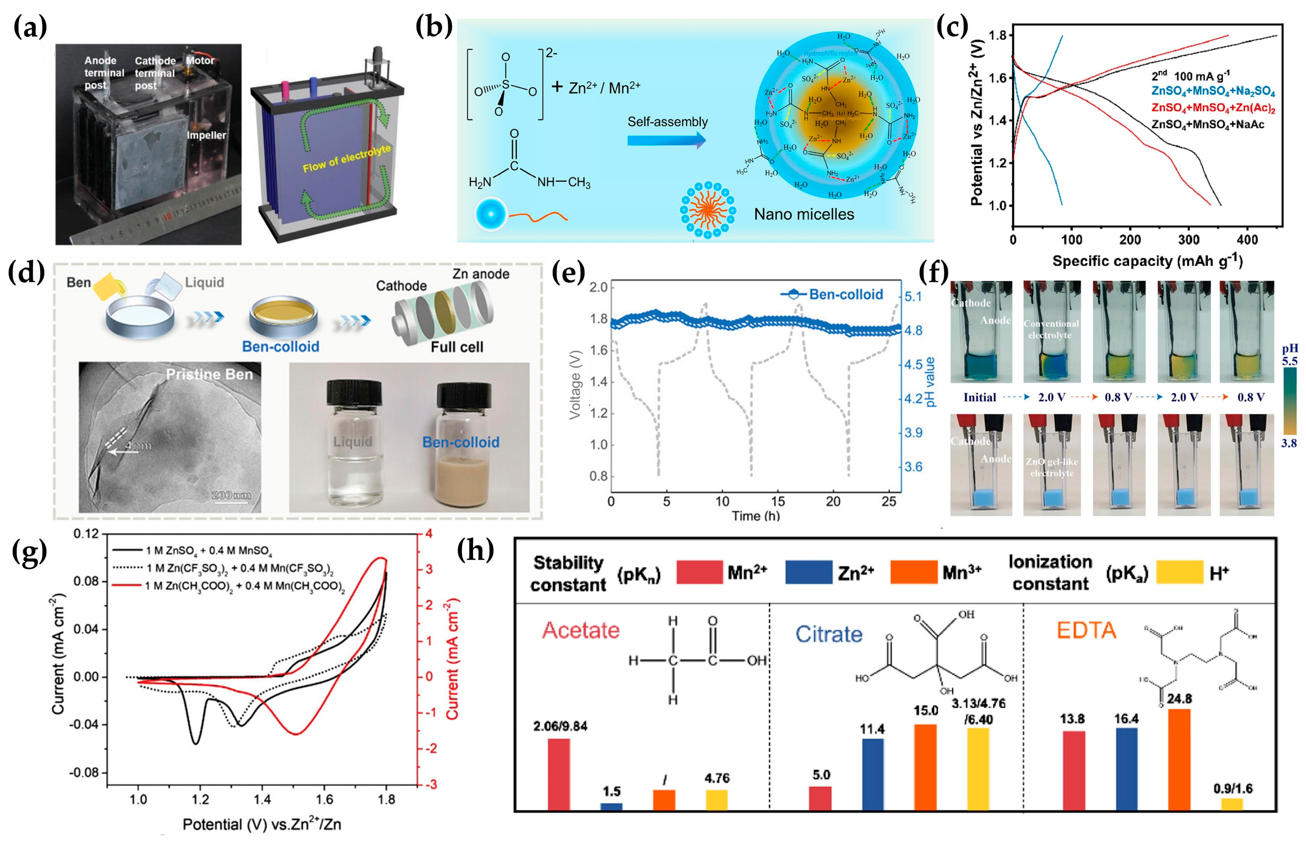
2. Electrolytes Modifications

2.1. Acid Electrolytes

Since Mn2+/MnO2 redox reactions are more favorable in acidic electrolytes, zinc metal anodes were initially deemed unsuitable for electrolytic MnO2 batteries due to hydrogen evolution issues [22,23]. Early studies instead explored alternative anodes such as hydrogen (H2) [24], Cu [22,23,25], Bi [22], Cd [23] and Pb [26]. For example, the MnO2–H2 battery utilized a 40% platinum-on-carbon catalyst to facilitate H2 reactions and employed a cylindrical structure for H2 storage (Figure 2a) [24]. While this system maintained a stable potential of ~1.254 V after 80 h of self-discharge, its remaining capacity was only ~71%. Metals stable in acidic electrolytes (e.g., Cu or Bi) were paired with MnO2, achieving open-circuit voltages below 1.2 V (Figure 2b) [22]. However, prolonged cycling revealed Cu2+ insertion into MnO2 at discharge voltages < 0.5 V. Then, hybrid systems integrating MnO2–Cu and MnO2–H2 via a two-step process were proposed, though at the cost of Cu consumption, H2SO4 usage, and excess energy input [25]. Alternatively, toxic Pb- and Cd-based MnO2 batteries achieved higher discharge voltages of 1.55 V and 1.68 V, respectively [23,26]. Notably, the MnO2/Mn2+ redox exhibited superior reversibility compared to commercial PbO2 cathodes, with higher current density and lower oxygen evolution overpotential (Figure 2c) [26].
The first Zn//electrolytic MnO2 battery demonstrated a high discharge voltage of 1.95 V, exceeding those of Zn2+ or H+ insertion mechanisms [20]. This system employed Zn foil, carbon cloth, and an electrolyte of 1 M ZnSO4 + 1 M MnSO4 + 0.1 M H2SO4. Initial charging deposited Zn and ε-MnO2, while subsequent cycles involved H+ and Zn2+ interactions (Figure 2d) [20]. Remarkably, the low-pH (~1) electrolyte maintained a stable pH and a 2.41 V working window for at least 50 cycles. Later studies showed that adding 0.07 mM polyvinylpyrrolidone (PVP) to this electrolyte significantly improved Coulombic efficiency and cyclability by modulating cationic solvation structures, enhancing Mn2+/Zn2+ migration and MnO2/Zn deposition–dissolution kinetics (Figure 3a) [27].
Beyond H2SO4, other acids such as HCl [28], acetic acid (HAc) [29,30,31] and methanesulfonic acid (MSA) [32] have been explored. Replacing 0.1 M H2SO4 with 0.2 M HAc in 1 M ZnSO4 + 1 M MnSO4 increased capacity contributions from (de)intercalation mechanisms (Figure 3b). HAc also reduced anode corrosion and hydrogen evolution while stabilizing pH fluctuations via reversible ionization (Figure 3c), leading to higher reversible capacity and improved cycling stability [29]. The pH buffering effect of HAc is due its weak acid nature compared with H2SO4 [19], which may be the case for MSA. Comparative studies of Zn//α-MnO2 batteries in 2 M ZnSO4 with 0.1 M MnSO4 or carboxylate additives highlighted the buffering effect of anions on interfacial H+ and steric hindrance of Mn2+ migration (Figure 3d) [33]. This mechanism may extend to cathode-free systems. Moreover, further increasing acetate content (e.g., 1 M ZnSO4 + 0.1 M MnSO4 + 0.1 M NaAc + 0.5 M HAc) shifted the dominant mechanism toward MnO2 deposition–dissolution by impeding H+/Zn2+ intercalation [30]. Further modification includes replacing sulfate with acetate and addition of KBr, which tripled ionic conductivity, likely due to Br integration into Zn2+/Mn2+ solvation shells, enhancing cation mobility [31]. In addition, charging protocols also impact performance; while high-voltage constant charging enables fast charging, it promotes Mn3+ formation, lowering Coulombic efficiency and cycle life (Figure 3e) [32].
Figure 2. Reaction mechanisms of Mn2+/MnO2 in acidic electrolytes: (a) schematic and digital photograph of the scaled-up membrane-free cylindrical Mn–H2 cell. Reproduced with permission from ref. [24]. Copyright 2018, Springer Nature; (b) pourbaix diagram of MnO2 cathode and Zn/Bi/Cu anode materials under varying pH conditions, to show the voltage difference. Reproduced with permission from ref. [22]. Copyright 2019, John Wiley & Son; (c) cyclic voltammetry (CV) comparison between Mn2+/MnO2 and PbSO4/PbO2 systems, where the currents indicate the reactivity. Reproduced with permission from ref. [26]. Copyright 2020, Royal Society of Chemistry; (d) schematic illustration of reactions steps for the zinc electrolytic MnO2 battery. Reproduced with permission from ref. [20]. Copyright 2019, John Wiley & Son: (top): Initial chronoamperometric charge process. Zn2+ and Mn2+ cations in the electrolyte are deposited onto the anode and cathode current collectors, forming metallic Zn and MnO2, respectively. (bottom): Subsequent reversible galvanostatic discharge and chronoamperometric charge cycles. During discharge, electrolytic MnO2 undergoes H+ and Zn2+ intercalation at the cathode, while Zn stripping and dissolution occur at the anode.
Batteries 11 00171 g002
Figure 3. Modifications for depositing MnO2 in acidic electrolytes: (a) schematic of the role of the cationic accelerator (PVP) in facilitating cation transport within aqueous MnO2–Zn batteries. Reproduced with permission from ref. [27]. Copyright 2022, John Wiley & Son; (b) galvanostatic discharge profiles and capacity contributions from MnO2 dissolution in electrolytes containing 0.1 M H2SO4 and 0.2 M HAc, where the high-voltage regions correspond deposition–dissolution process; (c) in situ pH measurements and corresponding H+ concentrations (circles) during cycling in a battery with 0.1 M HAc and 0.2 M H2SO4, where less pH fluctuation was showed for HAc case Reproduced with permission from ref. [29]. Copyright 2021, John Wiley & Son; (d) evolution of the electric double layer model at the cathode–electrolyte interface during charging: Modulation of interfacial H+ concentration and operating potential to thermodynamically enhance capacity. Reproduced with permission from ref. [33]. Copyright 2022, John Wiley & Son. (e) The effects of different charging conditions on the deposited MnO2. Reproduced with permission from ref. [32]. Copyright 2023, Elsevier.
Batteries 11 00171 g003

2.2. Dual Electrolytes

To mitigate Zn corrosion in acidic electrolytes, one strategy involves employing selective membranes and introducing a Zn-compatible secondary electrolyte [34,35]. Unlike the reactions in Figure 2d, the overall cell reaction shifts from Equations (R1) and (R2) to Equations (R1) and (R3), increasing the theoretical potential from 1.992 V to 2.428 V (Figure 4a).
Reactions:
Cathode: Mn2+ + 2H2O ⇄ MnO2 + 4H+ + 2e; E0 = 1.229 V vs. SHE
Anode (Acidic): Zn2+ + 2e ⇄ Zn; E0 = −0.763 V vs. SHE
Anode (Alkaline): Zn(OH)42− + 2e ⇄ Zn + 4OH; E0 = −1.199 V vs. SHE
Bipolar membranes (BPMs) were used to separate dual electrolytes, showing lower charge–discharge voltage gaps compared to anion/cation exchange membranes [36]. While BPMs allow H+/OH crossover to form water (Figure 4b) [36], another report adopts K+ and SO42− permeation [37]. Both systems achieved average voltages of ~2.44 V. Notably, introducing Ni2+ into the catholyte enhanced Mn2+/MnO2 electrolysis kinetics, improving the high-current (50 C) performance [36].
To prevent electrolyte neutralization, a neutral middle chamber separated by anion/cation exchange membranes was implemented (Figure 4c) [38]. Concentration gradients across the membranes generated an electric field, boosting the open-circuit voltage further to 2.83 V [38]. In this report, a scaled-up static pack powering LED panels using hybrid wind–photovoltaic energy was demonstrated. Similarly, a flow battery variant employed Bi2O3-modified carbon felt cathodes and Ni2+/Mg2+ catalysts in the catholyte was reported [39]. During charging process, Bi2O3 was dissolved and then reconstructed as nanosized crystal onto MnO2, while NiO2 formed from Ni2+. However, despite stable catholyte/anolyte pH, the middle chamber’s pH dropped from 4.8 to 2.35 after five cycles, indicating proton leakage [39].
For systems accepting discharge voltages of ~1.9 V, a membrane with solely anion or cation exchange functions were investigated. For instance, near-neutral anolytes (instead of alkaline) paired with anion exchange membranes (AEMs) were tested (Figure 4d) [40]. To protect the Zn anode from the leaked proton, ZnAc2 was applied at anolyte to trap the leaked protons [40]. To further shield the proton leakage, hydrophobic bis(trifluoromethylsulfonyl)imide (TFSI)-conducting membranes (PILG: polymer/ionic liquid/graphene) which selectively transported TFSI was applied [41]. However, both anolyte and catholyte required costly TFSI incorporation. As another case, a cation exchange membrane was applied to separate alkaline anolyte and mild acid catholyte; however, the MnO2 was pre-coated on the cathode first, which may be the reason for its inefficiency of MnO2 deposition in the mild acid environment [42].
Besides ion-exchange membranes, hydrogels and salt bridges were investigated to separate the dual electrolytes. As shown in Figure 4e, a Zn–MnO2 battery based on a liquid acidic catholyte coupled with KOH hydrogel and cellophane as a separator displayed an open-circuit voltage of 2.4–2.8 V [43]. Another cathode-free battery design, shown in Figure 4f, utilized a polyacrylamide (PAM)-based catholyte containing 1 M MnSO4 and 1 M H2SO4, along with an anolyte of 2 M ZnSO4 [44]. Furthermore, a tri-layer hydrogel electrolyte was reported, comprising an acidic region (PAM + ZnSO4 + H+), a buffer region (sodium polyacrylate (PAANa) + ZnSO4), and a conservation region (PAM + ZnSO4), as illustrated in Figure 4g [45]. Although this approach avoided the use of expensive ion-selective membranes, concerns regarding proton leakage persisted.
When a traditional salt bridge gel composed of Na2SO4 and agar was employed to separate the alkaline anolyte and acidic catholyte, a discharge voltage of 2.37 V was achieved, as depicted in Figure 4h [46]. For alternative salt bridge strategies, poly(vinyl alcohol) (PVA) gel was first immersed in ZnAc2 solution and then in concentrated ZnSO4 solution, leveraging strong Hofmeister effects to form a stable salt bridge interface (Figure 4i) [47]. Another study exploited the low solubility of K2SO4 in Pluronic F-127 (polyethylene–polypropylene glycol). When H2SO4 catholyte and KOH anolyte came into contact, a self-forming K2SO4 salt bridge was generated at the interface [48].
Figure 4. Battery configurations with dual electrolytes: (a) electrochemical stability window of the hybrid aqueous battery system and minimum electrolysis voltage required for stable operation; (b) schematic of a Zn//MnO2 hybrid aqueous battery employing dual electrolytes during charge/discharge cycles, where water is formed and decomposed within membranes. Reproduced with permission from ref. [36]. Copyright 2020, John Wiley & Son; (c) cell structure and reaction mechanisms in an aqueous decoupled Zn//MnO2 battery: Acidic and alkaline electrolytes (separated by a neutral central chamber) enable decoupled cathode and anode reactions during discharge/charge. Reproduced with permission from ref. [38]. Copyright 2020, Springer Nature; (d) pH evolution of the anolyte in an electrolyte-decoupled MnO2/Zn battery (i.e., acid + neutral electrolytes). Reproduced with permission from ref. [40]. Copyright 2022, American Chemical Society; (e) battery design utilizing alkaline KOH gel electrolyte paired with acidic liquid electrolyte. Reproduced with permission from ref. [43]. Copyright 2019, American Chemical Society; (f) schematic of a cathode-free battery integrating mixed and decoupled gel electrolytes. Reproduced with permission from ref. [44]. Copyright 2021, American Chemical Society; (g) tri-layer hydrogel electrolyte structure in a Zn//MnO2 battery, comprising “Acid zone”, “Buffer zone”, and “Conservation zone”. Reproduced with permission from ref. [45]. Copyright 2021, John Wiley & Son; (h) digital image of a electrolytes-decoupled glass electrolytic cell with a salt bridge. Reproduced with permission from ref. [46]. Copyright 2023, Elsevier; (i) fabrication of PVA-based salt bridge film via the Hofmeister effect. PZA sol denotes a light-white sol after addition of ZnAc2 (zinc acetate) to the PVA solution. PZAS gel denotes the PZA sol after addition of concentrated ZnSO4 which induces gelation. Reproduced with permission from ref. [47]. Copyright 2022, John Wiley & Son.
Batteries 11 00171 g004

2.3. Near Neutral Electrolytes

To eliminate the need for ion-selective membranes, near-neutral electrolytes have been investigated for depositing MnO2 while mitigating severe Zn anode corrosion. As illustrated in Figure 5a, a membrane-free flow battery was constructed using zinc foil and carbon felt electrodes with a 1 M MnSO4 + 1 M ZnSO4 electrolyte [17]. Additionally, another novel cell design further enhanced electrolyte utilization by rotating deposited MnO2 out of the electrolyte. A subsequent study revealed the detailed experimental parameters, including carbon current collector selection, electrolyte salt concentration/ratio, electrolyte volume, and battery configuration [49]. The results demonstrated that lower Zn2+ proportions improved discharge curve stability, while higher Mn2+ concentrations reduced pH (2~4) and elevated discharge voltage. However, excessively high Mn2+ concentrations (3 M) hindered MnO2 dissolution and induced salt precipitation, impairing long-term cycling performance [49].
To enhance the cycling stability of a cathode-free battery (control electrolyte: 0.5 M MnSO4 + 1 M ZnSO4), 7 M methylurea (Mu) was introduced. Mu, containing hydrophilic and hydrophobic moieties, transformed the electrolyte into a nanomicellar system (Figure 5b). These nanomicelles disrupted the continuous aqueous phase and its hydrogen-bonding network, restructuring local hydrogen bonds within micelles or at micelle–water interfaces. Additionally, Mu participated in Zn2+/Mn2+ solvation, displacing water molecules to lower desolvation energy barriers and regulate nanograin formation [50]. The restructured hydrogen-bonding network suppressed water decomposition and parasitic side reactions on the Zn anode. A protective solid–electrolyte interface (SEI) layer (Znx(Mu)ᵧSO4·nH2O) also formed, preventing anode corrosion. While the enlarged Zn2+ solvation radius ([Zn(Mu)x(H2O)ᵧ]2+) may hinder Zn2+ intercalation, the elevated pH (5.26) still favored MnO2 deposition [50]. In another report, glycine (Gly) was explored as an additive for 0.1 M MnSO4 + 1 M ZnSO4 electrolyte [56]. Gly complexes with Mn2+, releasing H+ to promote MnO2 dissolution at the cathode, while adsorbing on the Zn anode surface to shield it from detrimental reactions [56].
The cathode-free battery can also serve as a control sample for normal batteries where MnO2 is pre-coated on the cathode. For example, the addition of acetate additives to sulfate electrolytes significantly increased the battery capacity, as shown in Figure 5c. This enhanced capacity was validated using stainless steel as the cathode-free electrode, confirming the additional involvement of a dissolution–deposition mechanism [51]. Another example involves the incorporation of bentonite colloid (Ben-colloid) into the electrolyte (Figure 5d). The Ben colloid was hypothesized to self-concentrate Mn2+ ions and reduce the deposition potential, where a stainless steel was also applied as the cathode-free electrode [52]. Both studies demonstrated the pH buffering effect of these additives with weak acid nature, as illustrated in Figure 5e. Specifically, when excess 0.2 g/mL ZnO was introduced, a gel-like electrolyte formed, maintaining a stable pH of 6.4 throughout the charge–discharge cycles (Figure 5f) [53]. In this gel electrolyte, H+ ions were effectively eliminated, thereby promoting manganese deposition. Further analysis revealed that Mn2+ ions and ZBS synergistically generated Zn2Mn3O8·H2O nanorod arrays as active material during charging [53]. In a separate study, ZnO was incorporated onto electrodes, but its primary effect appeared to be limited to modifying the electrolyte’s pH [57]. Additionally, Mn(H2PO4)2 was employed as a pH buffering agent in chloride-based electrolytes [58]. The buffering mechanism for Mn2+/MnO2 conversion was further extended to weak Brønsted acids [59]. Without pH buffering additives, the chloride electrolyte was compared with other anion salts, where 3 M ZnCl2 + 0.1 M MnCl2 was recommended [60].
Acetate-based (Ac) electrolytes have been extensively studied. Cyclic voltammetry (CV) of acetate-, sulfate-, and sulfonate-based electrolytes (1 M Zn2+ + 0.4 M Mn2+, Figure 5g) revealed distinct reaction mechanisms: acetate electrolytes exhibited a two-electron MnO2/Mn2+ reaction (reduction peak at 1.5 V), whereas sulfate/sulfonate systems showed Zn2+/H+ insertion into the MnO2 cathode, characterized by dual reduction peaks at 1.35 V and 1.2 V [54]. Complete MnO2 dissolution after discharge was confirmed in acetate electrolytes. Density functional theory (DFT) calculations indicated that acetate anions adsorb onto MnO2 surface sites, weakening H2O binding and reducing dissolution energy barriers [54]. Thus, acetate anions enhanced Zn anode compatibility. A flow battery utilizing 0.5 M MnAc2 + 0.5 M ZnCl2 + 2 M KCl as electrolyte achieved an area capacity of 10 mAh/cm2 [61]. After applying carbon black coating and higher electrolyte concentrations, the capacity further increased to 20 mAh/cm2. Subsequent optimization of electrolyte to 1 M MnAc2 + 1 M ZnAc2 + 2 M KCl fully coordinated generated H+, achieving an energy density of 42 Wh/L in static batteries [61]. Although Mn3+ disproportionation was not detected with Na4P2O7 as an indicator, ethylenediaminetetraacetate (EDTA) confirmed Mn3+ presence due to its stronger complexation capability than Ac [55,61]. Citrate and EDTA were further compared with acetate as complexing agents (Figure 5h). However, citrate electrolytes exhibited lower pH, while EDTA-based batteries suffered from self-discharge [55]. The criteria for selecting optimal complexing agents were proposed as follows [55]: (i) strong Mn2+ binding affinity to limit free Mn2+ concentration; (ii) minimal H+ consumption to maintain higher reaction potentials; (iii) weak interactions with Zn2+ and Mn3+ to avoid competitive binding (Zn2+ vs. Mn2+) or MnO2 suspension (Mn3+-induced instability), thereby preserving Coulombic efficiency (CE).

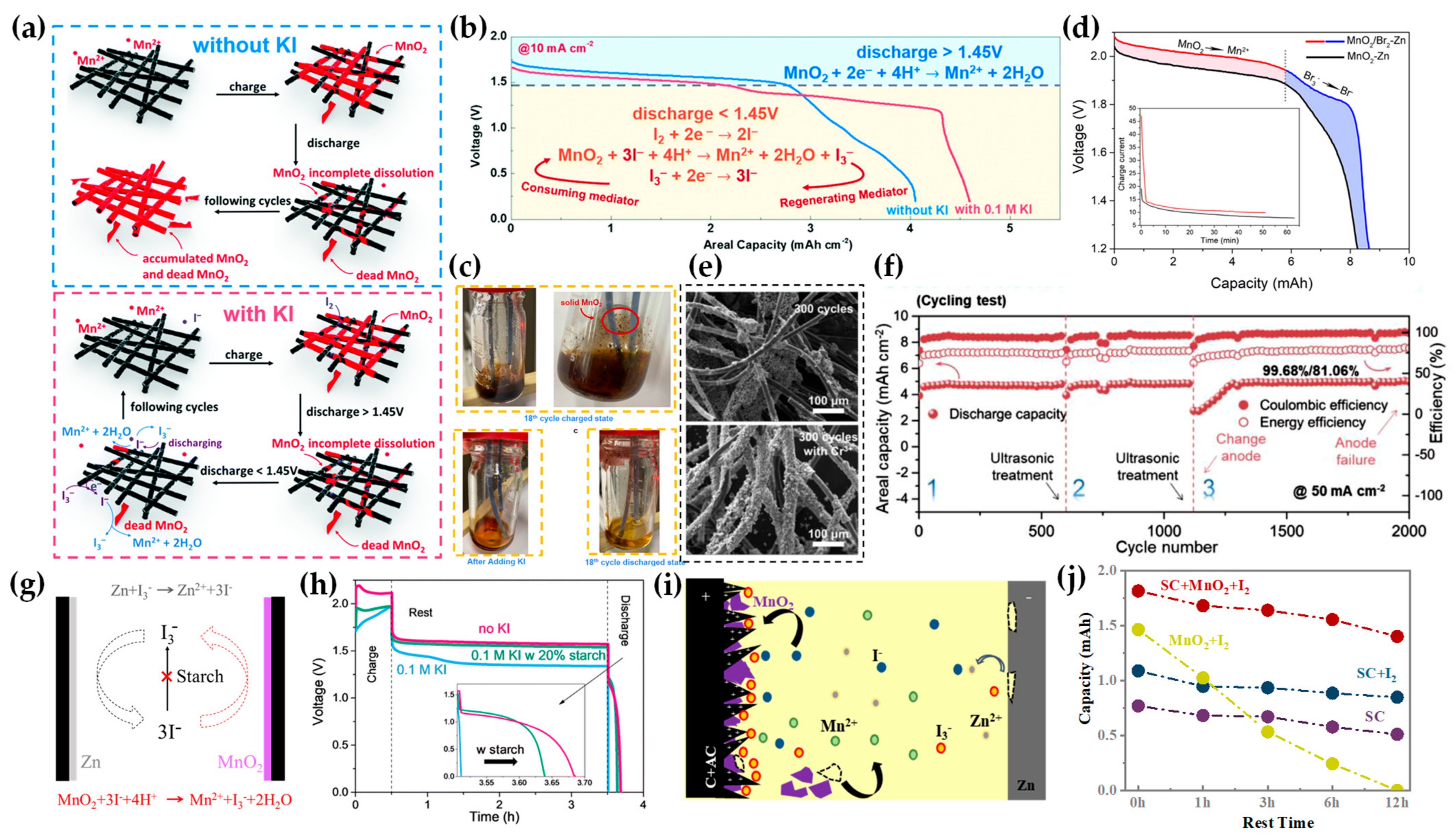
2.4. Mediator Additives

The disproportionation reaction of oxidized Mn3+ (2Mn3+ + 2H2O → MnO2 + 4H+ + Mn2+) leads to the formation of “dead” MnO2, which detaches from current collectors [32,55,61,62]. To recycle the dead MnO2, mediator additives are introduced into the electrolyte to reduce it back to Mn2+. As shown in Figure 6a,b, the addition of iodide (I) enables the oxidation of iodide to I3, facilitating the conversion of solid MnO2 into soluble Mn2+ [63]. Figure 6c demonstrates that dead MnO2 dispersing in the electrolyte after 18 cycles and can be dissolved completely upon adding KI, resulting in a transparent solution. Moreover, the generated I3 is also found to contribute to capacity as zinc–iodine batteries [63,64,65]. Similarly, bromide (Br) is proved to enhance capacity (Figure 6d), but its oxidation requires a high charging voltage (e.g., 2.2 V as the case in acidic sulfate electrolytes) [66]. When the charging voltage is fixed below 1.8 V, no Br2 forms, and Br primarily functions to improve electrolyte ion conductivity [31,65]. When chromium cations (Cr3+, with Cr2+/Cr3+ redox potential at −0.407 V vs. SHE, higher than Zn/Zn2+ at −0.763 V vs. SHE) act as mediators, uniform MnO2 deposition is promoted (Figure 6e) [55]. Additionally, ultrasonic treatment was proposed to recover batteries by dislodging over-thick MnO2 layers (Figure 6f) [55].
Although mediator additives improve capacity and MnO2 recovery, they also induce shuttle reactions with both electrodes [21,67,68]. These reactions become severe in thin-film batteries with limited electrolyte volume and narrow electrode gaps (Figure 6g). To mitigate this, starch was added to coordinate with I3, significantly extending battery shelf life (Figure 6h) [21,68]. Another strategy to mitigate shuttling employs activated carbon electrodes [67]. Compared to graphite, activated carbon’s high surface area provides more sites for MnO2 anchoring. Furthermore, positive charges accumulating at the cathode (supercapacitor-like effect) electrostatically attract I3. Combined with reduced MnO2 detachment and electrostatic interactions, this approach enhances both Coulombic efficiency and shelf life (Figure 6i,j) [67].

3. Electrode Modifications

3.1. Anode Modifications

For Zn anodes, constructing a solid electrolyte interface (SEI) is a common strategy to combat hydrogen evolution corrosion (HEC) caused by acidic electrolytes. A proton-resistant Pb-containing interface (composed of Pb and Pb(OH)2) was formed on Zn anodes (denoted as Zn@Pb) via a facile displacement reaction (i.e., immersing Zn foil in PbAc2 solution). This interface further transformed in situ into PbSO4 upon H2SO4 corrosion [69]. When PbAc2 was further added to the working electrolyte, Zn anode stability was significantly enhanced (Figure 7a,b). In situ XRD analysis revealed that Pb is plated and stripped on the anode surface during cycling. The Pb layer protects the Zn plating layer from HEC throughout the plating/stripping process due to Pb’s low affinity for H+ and strong Pb–Zn/Pb–Pb bonding [69].
In another report, a phytic acid (PA)-modified layer was fabricated by soaking Zn foil in a 1% PA solution [70]. Instead of H2SO4, H3PO4 was used as an acidic additive in the electrolyte. As shown in Figure 7c,d, incorporating H3PO4 suppressed hydrogen evolution, with an optimal electrolyte pH of 2.2. However, even with the PA-modified layer, HEC occurred when H2SO4 was introduced [70]. This occurred because zinc phosphate formation at the interface is necessary. During the Zn stripping, Zn2+ ions accumulate at the interface to form zinc phosphate (Zn3(PO4)2·4H2O, ZPO) and zinc hydroxide sulfate (Zn4SO4(OH)6·5H2O, ZHS) at the PA-modified layer. Subsequently, during Zn plating, H+ ions migrate alongside Zn2+ to the anode, where they are adsorbed by the PA-modified layer and absorbed by ZPO/ZHS. Throughout repeated plating/stripping cycles, H+ ions are reversibly adsorbed within the interphase, maintaining a stable proton concentration in the electrolyte [70].

3.2. Cathode Modifications

For most studied pre-coated MnO2 batteries, constructing a cathode electrolyte interface (CEI) is a common strategy to suppress MnO2 dissolution. Here, the CEI layer prevents dead MnO2 dispersion into the electrolyte via limiting Mn2+ diffusion. However, though we need the CEI to capture Mn3+ and H+, the CEI layer must also allow MnO2/Mn2+ redox reactions, as illustrated in Figure 7e [71]. After evaluating the electrostatic potential distributions of monomers, including acrylamide (AAm), 2-acrylamido-2-methylpropanesulfonic acid (AMPS), 2-chloroacrylic acid (ClAA), acrylic acid (AA), methacrylic acid (MAA), and vinylphosphonic acid (VPA), MAA was selected for in situ gel polymerization on carbon cloth (PMAA@CC) in the presence of Zn2+ and Mn2+ [71]. By minimizing dead MnO2 in the electrolyte, H+ generation is reduced, which in turn mitigates Zn anode corrosion and enhancing the reversibility of MnO2/Mn2+ reactions. Another approach to suppress Mn3+ diffusion and disproportionation involves manganese polyacrylate (PAAMn), which was coated on stainless steel foil as a cathode active material [72]. Due to the relatively low ion conductivity, the diffusion of Mn3+ may also be limited in hydrogels, as reported in refs. [44,45,73,74].
Doping deposited MnO2 is an effective method to improve conductivity. In dual-electrolyte systems, Ni3+ and Bi3+ doping catalyzes Mn2+/MnO2 reactions and enhances MnO2 conductivity without concerns about cation crossover due to anolyte/catholyte separation [36,39,75]. For single-electrolyte batteries, bismuth (III) pyridine-3,5-dicarboxylate (BiMOF) was employed as a Bi3+ reservoir to stabilize MnO2 structure by controlled Bi3+ release during Mn2+ deposition [76]. Similarly, adding Al3+ to the electrolyte was reported to form a proton–donor reservoir to maintain acidic conditions and to introduce oxygen vacancies into MnO2 [77].
As different phases were reported for the deposited MnO2, the crystal structure may vary with factors, such as anions, pH, and charging protocols. Notably, incorporating 0.1 mM surfactant molecules into the electrolyte induces favorable c-axis orientation in hexagonal Zn and MnO2 deposition (Figure 7f) [78]. The surfactant (e.g., t-Oct-C6H4-(OCH2CH2)nOH, n ≈ 9–10) with hydrophobic tail and hydrophilic head first form an aligned bilayer structure, followed by a gradient liquid crystal interphase during deposition. This interphase comprises lamellar liquid crystals (near the electrode), hexagonal liquid crystals (intermediate), and micelle clusters (near the electrolyte). Consequently, the layered δ-phase MnO2 was deposited instead of the ε-phase. (Figure 7g). Additionally, the surfactant promotes (002) plane growth of Zn, yielding a flat, compact anode morphology with enhanced corrosion resistance against hydrogen evolution [78].
Figure 7. Anti-corrosion strategies for Zn anodes and modifications to mitigate dissolution and crystal structures of MnO2 cathode: (a) cycling performance of Zn@Pb-Ad (Ad denotes PbAc2 additive in electrolyte), Zn@Pb, and bare Zn symmetric batteries in 0.2 M H2SO4 (4 mA cm−2, 0.5 mAh cm−2); (b) post-cycling photographs of Zn symmetric batteries, where the control bare Zn anode fell apart. Reproduced with permission from ref. [69]. Copyright 2023, John Wiley & Son; (c) optical images of Zn deposition on PAZn anodes with H3PO4 (PS) or H2SO4 (SS) additives at 30 mA cm−2 for 6 min. Hydrogen bubble formed for the H2SO4 case; (d) linear sweep voltammetry (LSV) curves of PAZn anodes in 1 M Na2SO4 at varying pH adjusted by H3PO4/H2SO4. The S shape curve for the H3PO4 case indicates the existence of optimal pH value. Reproduced with permission from ref. [70]. Copyright 2025, John Wiley & Son; (e) in situ hydrogel ion-anchoring strategy to form CEI for suppressing Mn3+ and H+ diffusion. Reproduced with permission from ref. [71]. Copyright 2024, American Chemical Society; (f) dynamic phase transition during deposition: from aligned surfactant bilayers to gradient liquid crystal interphases (lamellar near the electrode, hexagonal intermediate, and micelle clusters near the electrolyte); (g) TEM images of MnO2 deposited in pristine electrolyte (ε-phase, (top)) versus surfactant-modified electrolyte (δ-phase, (bottom)). Reproduced with permission from ref. [78]. Copyright 2024, Springer Nature.
Batteries 11 00171 g007

3.3. Current Collectors

For the cathode-free structure, the initial charging process deposits MnO2 from the electrolyte onto current collectors. During this step, metallic zinc is also plated, suggesting that a conventional zinc foil anode may be unnecessary. A dual electrode-free structure—using current collectors as initial electrodes—was demonstrated in MnO2–Cd/Zn/Cu batteries (Figure 8a) [21,23,78,79]. Furthermore, the cycling performance of cuvette cells and thin-film batteries with/without zinc anodes was compared using an electrolyte containing 1 M ZnAc2 + 1 M MnAc2 + 2 M KCl + 0.1 M KI. Results showed that electrode-free thin-film batteries (carbon//carbon configuration) exhibited lower Coulombic efficiencies (CEs) but longer cycle life than Zn//carbon systems (Figure 8b) [21]. Thus, although excess zinc compensates for deposition inefficiency and corrosion losses, it intensifies hydrogen evolution side reactions. Hydrogen generation caused battery inflation and failure, particularly sensitive in sealed thin-film structures with lean electrolyte volume and confined space, which are closer to real-world applications [21].
Interestingly, the electrode-free design enables a facile assembly of batteries with complex geometries. For example, a cable-shaped battery was fabricated by embedding two commercial carbon fiber ropes in a starch gel electrolyte (Figure 8c) [21,68]. During initial charging, Zn and MnO2 were directly deposited on the fibers, eliminating troublesome pre-coating steps. Here, the starch additive not only stabilized the gel electrolyte but also suppressed iodide-mediated shuttle reactions [21,68]. Another example is a micro-battery (Figure 8c), where polyacrylamide (PAM) hydrogel was applied to microelectrodes [79]. After full discharge, the battery reverts to its initial state (only current collectors), enabling polarity switching (Figure 8d,e). This feature enhances safety during over-discharge and expands application flexibility [21,79].
Integrating supercapacitor electrodes with the electrolyte of a zinc electrolytic MnO2 battery yielded a hybrid “supercapattery” (Figure 8f) [67]. For conventional supercapacitors, the stored charge quantity Q is only proportional to charged voltage V, if the capacitance C is fixed, i.e., Q = C × V. However, the electrochemical working window of the aqueous electrolytes is limited by the water decomposition. Thus, we integrated the two types of devices by leveraging Zn–I2 and Zn–MnO2 charge/discharge platforms, circumventing water decomposition limits. Furthermore, the iodide additive can recover dead MnO2. Overall, a flexible thin-film device that combines supercapacitor, Zn–I2 and Zn–MnO2 functionalities was demonstrated (Figure 8g). This integration outperformed individual components in capacity, shelf life, and cycle stability [67].

4. Outlooks and Perspectives

To reveal detailed information about the reviewed battery structures, Table 1 lists the electrode materials and electrolyte formulations. By categorizing recent strategies for performance and stability enhancement into electrolyte and electrode modifications, we propose the following possible research directions:
Electrolyte pH: Although initial electrolytes may be neutral, the charging process will generate H+, which inevitably acidifies the electrolyte. This acidic environment accelerates Zn anode corrosion and hydrogen evolution, leading to gas-induced battery inflation.
Electrolyte Volume: While electrolytes serve as material sources for Zn//MnO2 deposition, excessive volumes (taking 30 µL/cm2 for thin-film battery as a reference) reduce material utilization efficiency. Optimization should balance electrolyte quantity with deposition kinetics.
Zn Anode: Despite advances in Zn alloys and SEI layers for widely studied zinc–ion batteries (mostly based on mild acid sulphate electrolytes), their application in electrolytic MnO2 systems (mostly based on in acid or acetate electrolytes) remains unexplored. Translating these innovations may mitigate corrosion and hydrogen evolution.
MnO2 Cathode: Industrial electrolytic manganese dioxide (EMD) dominates the primary market. Studying doping and phase transitions during in situ MnO2 electrodeposition may help to refine EMD production processes.
Current Collectors: Excess Zn addition compensates for anode loss but obscures the reaction mechanisms. Single or dual electrode-free configurations are recommended as control experiment samples. Additionally, alignment between real-world application conditions and laboratory battery designs should be considered. For instance, carbon cloth/felt’s high surface area differs significantly from printed electrodes, potentially limiting practical relevance.
Battery Design: Thin-film batteries with lean electrolytes and compact dimensions closely mimic real-world applications. These structures are highly sensitive to hydrogen accumulation and have been commercialized (e.g., Zinergy’s products).
Shelf Life: Long-term stability tests are critical, especially for systems employing mediator additives prone to shuttle reactions.
Integrated Devices: Activated carbon electrodes enhance MnO2 anchoring and contribute pseudocapacitive capacity. Hybrid supercapattery designs (combining supercapacitors with Zn–MnO2/I2 chemistries) offer superior performance and novel mechanistic pathways.

Author Contributions

S.L. (Shiwei Liu): Data curation; Visualization; Validation; Software. Z.L.: Methodology; Investigation. H.Z.: Resources, Funding acquisition. W.C.: Methodology. J.W.: Resources. Q.Z.: Methodology. G.Y.: Formal analysis. W.A.D.: Resources. Z.N.: Funding acquisition; Project administration. P.H.: Funding acquisition; Project administration. S.L. (Shiqiang Luo): Conceptualization; Writing—Original draft preparation. G.A.J.A.: Supervision; Writing—Review and Editing. All authors have read and agreed to the published version of the manuscript.

Funding

This research was funded by the Guangdong Introducing Innovative and Entrepreneurial Teams Program, grant number 2019ZT08Z656 and by the Shenzhen Science and Technology Program, grant number KJZD20230923113759002, SZXJP20230703093207017 and KQTD20190929172522248.

Data Availability Statement

The data presented in this study are available upon request from the corresponding authors.

Acknowledgments

This work is supported by the Guangdong Introducing Innovative and Entrepreneurial Teams Program, the Shenzhen Science and Technology Program and the Shenzhen Association for Science and Technology.

Conflicts of Interest

Authors Shiwei Liu, Zanxiang Nie, Pritesh Hiralal, Shiqiang Luo and Gehan A. J. Amaratunga were employed by Zinergy Shenzhen Ltd. The remaining authors declare that the research was conducted in the absence of any commercial or financial relationships that could be construed as a potential conflict of interest.

References

  1. Luan, J.; Yuan, H.; Liu, J.; Zhong, C. Recent advances on charge storage mechanisms and optimization strategies of Mn-based cathode in zinc-manganese oxides batteries. Energy Storage Mater. 2024, 66, 103206. [Google Scholar] [CrossRef]
  2. Zhang, Z.; Li, W.; Shen, Y.; Wang, R.; Li, H.; Zhou, M.; Wang, W.; Wang, K.; Jiang, K. Issues and opportunities of manganese-based materials for enhanced Zn-ion storage performances. J. Energy Storage 2022, 45, 103729. [Google Scholar] [CrossRef]
  3. Shoji, T.; Hishinuma, M.; Yamamoto, T. Zinc-manganese dioxide galvanic cell using zinc sulphate as electrolyte. Rechargeability of the cell. J. Appl. Electrochem. 1988, 18, 521–526. [Google Scholar] [CrossRef]
  4. Xu, C.J.; Li, B.H.; Du, H.D.; Kang, F.Y. Energetic Zinc Ion Chemistry: The Rechargeable Zinc Ion Battery. Angew. Chem. Int. Edit. 2012, 51, 933–935. [Google Scholar] [CrossRef]
  5. Sambandam, B.; Mathew, V.; Kim, S.; Lee, S.; Kim, S.; Hwang, J.Y.; Fan, H.J.; Kim, J. An analysis of the electrochemical mechanism of manganese oxides in aqueous zinc batteries. Chem 2022, 8, 924–946. [Google Scholar] [CrossRef]
  6. Zhang, N.; Ji, Y.-R.; Wang, J.-C.; Wang, P.-F.; Zhu, Y.-R.; Yi, T.-F. Understanding of the charge storage mechanism of MnO2-based aqueous zinc-ion batteries: Reaction processes and regulation strategies. J. Energy Chem. 2023, 82, 423–463. [Google Scholar] [CrossRef]
  7. Zhang, N.; Wang, J.C.; Guo, Y.F.; Wang, P.F.; Zhu, Y.R.; Yi, T.F. Insights on rational design and energy storage mechanism of Mn-based cathode materials towards high performance aqueous zinc-ion batteries. Coordin. Chem. Rev. 2023, 479, 215009. [Google Scholar] [CrossRef]
  8. Lee, B.; Lee, H.R.; Kim, H.; Chung, K.Y.; Cho, B.W.; Oh, S.H. Elucidating the intercalation mechanism of zinc ions into alpha-MnO2 for rechargeable zinc batteries. Chem. Commun. 2015, 51, 9265–9268. [Google Scholar] [CrossRef]
  9. Chamoun, M.; Brant, W.R.; Tai, C.W.; Karlsson, G.; Noreus, D. Rechargeability of aqueous sulfate Zn/MnO2 batteries enhanced by accessible Mn2+ ions. Energy Storage Mater. 2018, 15, 351–360. [Google Scholar] [CrossRef]
  10. Yuan, Y.F.; Sharpe, R.; He, K.; Li, C.H.; Saray, M.T.; Liu, T.C.; Yao, W.T.; Cheng, M.; Jin, H.L.; Wang, S.; et al. Understanding intercalation chemistry for sustainable aqueous zinc-manganese dioxide batteries. Nat. Sustain. 2022, 5, 890–898. [Google Scholar] [CrossRef]
  11. Pan, H.; Shao, Y.; Yan, P.; Cheng, Y.; Han, K.S.; Nie, Z.; Wang, C.; Yang, J.; Li, X.; Bhattacharya, P.; et al. Reversible aqueous zinc/manganese oxide energy storage from conversion reactions. Nat. Energy 2016, 1, 16039. [Google Scholar] [CrossRef]
  12. Kim, S.H.; Oh, S.M. Degradation mechanism of layered MnO2 cathodes in Zn/ZnSO4/MnO2 rechargeable cells. J. Power Sources 1998, 72, 150–158. [Google Scholar] [CrossRef]
  13. Wu, D.R.; Housel, L.M.; Kim, S.J.; Sadique, N.; Quilty, C.D.; Wu, L.J.; Tappero, R.; Nicholas, S.L.; Ehrlich, S.; Zhu, Y.M.; et al. Quantitative temporally and spatially resolved X-ray fluorescence microprobe characterization of the manganese dissolution-deposition mechanism in aqueous Zn/alpha-MnO2 batteries. Energ. Environ. Sci. 2020, 13, 4322–4333. [Google Scholar] [CrossRef]
  14. Moon, H.; Ha, K.H.; Park, Y.; Lee, J.; Kwon, M.S.; Lim, J.; Lee, M.H.; Kim, D.H.; Choi, J.H.; Choi, J.H.; et al. Direct Proof of the Reversible Dissolution/Deposition of Mn2+/Mn4+ for Mild-Acid Zn-MnO2 Batteries with Porous Carbon Interlayers. Adv. Sci. 2021, 8, 2003714. [Google Scholar] [CrossRef] [PubMed]
  15. Guo, X.; Zhou, J.; Bai, C.L.; Li, X.K.; Fang, G.Z.; Liang, S.Q. Zn/MnO2 battery chemistry with dissolution-deposition mechanism. Mater. Today Energy 2020, 16, 100396. [Google Scholar] [CrossRef]
  16. Chen, H.; Dai, C.L.; Xiao, F.Y.; Yang, Q.J.; Cai, S.N.; Xu, M.W.; Fan, H.J.; Bao, S.J. Reunderstanding the Reaction Mechanism of Aqueous Zn-Mn Batteries with Sulfate Electrolytes: Role of the Zinc Sulfate Hydroxide. Adv. Mater. 2022, 34, 2109092. [Google Scholar] [CrossRef] [PubMed]
  17. Li, G.D.; Chen, W.; Zhang, H.; Gong, Y.J.; Shi, F.F.; Wang, J.Y.; Zhang, R.F.; Chen, G.X.; Jin, Y.; Wu, T.; et al. Membrane-Free Zn/MnO2 Flow Battery for Large-Scale Energy Storage. Adv. Energy Mater. 2020, 10, 1902085. [Google Scholar] [CrossRef]
  18. Yang, H.; Zhou, W.H.; Chen, D.; Liu, J.H.; Yuan, Z.Y.; Lu, M.J.; Shen, L.F.; Shulga, V.; Han, W.; Chao, D.L. The origin of capacity fluctuation and rescue of dead Mn-based Zn-ion batteries: A Mn-based competitive capacity evolution protocol. Energ. Environ. Sci. 2021, 15, 1106–1118. [Google Scholar] [CrossRef]
  19. Liu, Z.; Qin, L.; Lu, B.; Wu, X.; Liang, S.; Zhou, J. Issues and Opportunities Facing Aqueous Mn2+/MnO2-based Batteries. ChemSusChem 2022, 15, e202200348. [Google Scholar] [CrossRef]
  20. Chao, D.L.; Zhou, W.H.; Ye, C.; Zhang, Q.H.; Chen, Y.G.; Gu, L.; Davey, K.; Qiao, S.Z. An Electrolytic Zn-MnO2 Battery for High-Voltage and Scalable Energy Storage. Angew. Chem. Int. Ed. 2019, 58, 7823–7828. [Google Scholar] [CrossRef]
  21. Luo, S.; Liu, S.; Yang, G.; Liu, C.; Wu, J.; Hiralal, P.; Nie, Z.; Amaratunga, G.A.J.; Zhou, H. Electrode-free flexible batteries enabled by electro-deposition of both Zn and MnO2 from electrolytes. New J. Chem. 2024, 48, 1462–1466. [Google Scholar] [CrossRef]
  22. Liang, G.; Mo, F.; Li, H.; Tang, Z.; Liu, Z.; Wang, D.; Yang, Q.; Ma, L.; Zhi, C. A Universal Principle to Design Reversible Aqueous Batteries Based on Deposition–Dissolution Mechanism. Adv. Energy Mater. 2019, 9, 1901838. [Google Scholar] [CrossRef]
  23. Wang, M.; Chen, N.; Zhu, Z.; Meng, Y.; Shen, C.; Zheng, X.; Liang, D.; Chen, W. Electrode-Less MnO2-Metal Batteries with Deposition and Stripping Chemistry. Small 2021, 17, 2103921. [Google Scholar] [CrossRef] [PubMed]
  24. Chen, W.; Li, G.; Pei, A.; Li, Y.; Liao, L.; Wang, H.; Wan, J.; Liang, Z.; Chen, G.; Zhang, H.; et al. A manganese–hydrogen battery with potential for grid-scale energy storage. Nat. Energy 2018, 3, 428–435. [Google Scholar] [CrossRef]
  25. Huang, J.; Guo, Z.; Dong, X.; Bin, D.; Wang, Y.; Xia, Y. Low-cost and high safe manganese-based aqueous battery for grid energy storage and conversion. Sci. Bull. 2019, 64, 1780–1787. [Google Scholar] [CrossRef]
  26. Huang, J.; Yan, L.; Bin, D.; Dong, X.; Wang, Y.; Xia, Y. An aqueous manganese–lead battery for large-scale energy storage. J. Mater. Chem. A 2020, 8, 5959–5967. [Google Scholar] [CrossRef]
  27. Chuai, M.Y.; Yang, J.L.; Tan, R.; Liu, Z.C.; Yuan, Y.; Xu, Y.; Sun, J.F.; Wang, M.M.; Zheng, X.H.; Chen, N.; et al. Theory-Driven Design of a Cationic Accelerator for High-Performance Electrolytic MnO2-Zn Batteries. Adv. Mater. 2022, 34, 2203249. [Google Scholar] [CrossRef]
  28. Feng, Z.Y.; Gao, Z.Y.; Xue, Z.Y.; Yang, M.; Zhao, X.Y. Acidity Modulation of Electrolyte Enables High Reversible Mn2+/MnO2 Electrode Reaction of Electrolytic Zn-MnO2 Battery. J. Electron. Mater. 2022, 51, 6041–6046. [Google Scholar] [CrossRef]
  29. Liu, Z.X.; Yang, Y.Q.; Liang, S.Q.; Lu, B.A.; Zhou, J. pH-Buffer Contained Electrolyte for Self-Adjusted Cathode-Free Zn-MnO2 Batteries with Coexistence of Dual Mechanisms. Small Struct. 2021, 2, 2100119. [Google Scholar] [CrossRef]
  30. He, Z.F.; Lu, Y.T.; Wei, T.C.; Hu, C.C. Complementary Operando Electrochemical Quartz Crystal Microbalance and UV/Vis Spectroscopic Studies: Acetate Effects on Zinc-Manganese Batteries. ChemSusChem 2023, 16, e202300259. [Google Scholar] [CrossRef]
  31. Wu, J.; Li, Y.N.; Huang, J.Q.; Chi, X.W.; Yang, J.H.; Liu, Y. Bromide-acetate co-mediated high-power density rechargeable aqueous zinc-manganese dioxide batteries. J. Mater. Chem. A 2021, 9, 21888–21896. [Google Scholar] [CrossRef]
  32. Wang, H.; Wang, T.; Stevenson, G.; Chamoun, M.; Lindström, R.W. MnO2/Mn2+ chemistry: Charging protocol and electrolyte regulation. Energy Storage Mater. 2023, 63, 103008. [Google Scholar] [CrossRef]
  33. Liu, Z.; Li, L.; Qin, L.; Guo, S.; Fang, G.; Luo, Z.; Liang, S. Balanced Interfacial Ion Concentration and Migration Steric Hindrance Promoting High-Efficiency Deposition/Dissolution Battery Chemistry. Adv. Mater. 2022, 34, 2204681. [Google Scholar] [CrossRef] [PubMed]
  34. Durena, R.; Zukuls, A. A Short Review: Comparison of Zinc-Manganese Dioxide Batteries with Different pH Aqueous Electrolytes. Batteries 2023, 9, 311. [Google Scholar] [CrossRef]
  35. Dai, C.; Hu, L.; Jin, X.; Zhao, Y.; Qu, L. The Emerging of Aqueous Zinc-Based Dual Electrolytic Batteries. Small 2021, 17, e2008043. [Google Scholar] [CrossRef] [PubMed]
  36. Chao, D.; Ye, C.; Xie, F.; Zhou, W.; Zhang, Q.; Gu, Q.; Davey, K.; Gu, L.; Qiao, S.-Z. Atomic Engineering Catalyzed MnO2 Electrolysis Kinetics for a Hybrid Aqueous Battery with High Power and Energy Density. Adv. Mater. 2020, 32, 2001894. [Google Scholar] [CrossRef]
  37. Liu, C.; Chi, X.; Han, Q.; Liu, Y. A High Energy Density Aqueous Battery Achieved by Dual Dissolution/Deposition Reactions Separated in Acid-Alkaline Electrolyte. Adv. Energy Mater. 2020, 10, 1903589. [Google Scholar] [CrossRef]
  38. Zhong, C.; Liu, B.; Ding, J.; Liu, X.R.; Zhong, Y.W.; Li, Y.; Sun, C.B.; Han, X.P.; Deng, Y.D.; Zhao, N.Q.; et al. Decoupling electrolytes towards stable and high-energy rechargeable aqueous zinc-manganese dioxide batteries. Nat. Energy 2020, 5, 440–449. [Google Scholar] [CrossRef]
  39. Kim, M.; Lee, S.; Choi, J.; Park, J.; Park, J.W.; Park, M. Reversible metal ionic catalysts for high-voltage aqueous hybrid zinc-manganese redox flow batteries. Energy Storage Mater. 2023, 55, 698–707. [Google Scholar] [CrossRef]
  40. Sun, J.F.; Liu, Z.C.; Li, K.; Yuan, Y.; Zheng, X.H.; Xu, Y.; Wang, M.M.; Chuai, M.; Hu, H.L.; Chen, W. Proton-Trapping Agent for Mitigating Hydrogen Evolution Corrosion of Zn for an Electrolytic MnO2/Zn Battery. ACS Appl. Mater. Interfaces 2022, 14, 51900–51909. [Google Scholar] [CrossRef]
  41. Cui, Y.F.; Zhuang, Z.B.; Xie, Z.L.; Cao, R.F.; Hao, Q.; Zhang, N.; Liu, W.Q.; Zhu, Y.H.; Huang, G. High-Energy and Long-Lived Zn-MnO2 Battery Enabled by a Hydrophobic-Ion- Conducting Membrane. ACS Nano 2022, 16, 20730–20738. [Google Scholar] [CrossRef] [PubMed]
  42. Fan, W.J.; Liu, F.; Liu, Y.; Wu, Z.X.; Wang, L.L.; Zhang, Y.; Huang, Q.H.; Fu, L.J.; Wu, Y.P. A high voltage aqueous zinc-manganese battery using a hybrid alkaline-mild electrolyte. Chem. Commun. 2020, 56, 2039–2042. [Google Scholar] [CrossRef] [PubMed]
  43. Yadav, G.G.; Turney, D.; Huang, J.C.; Wei, X.; Banerjee, S. Breaking the 2 V Barrier in Aqueous Zinc Chemistry: Creating 2.45 and 2.8 V MnO2-Zn Aqueous Batteries. ACS Energy Lett. 2019, 4, 2144–2146. [Google Scholar] [CrossRef]
  44. Tang, H.; Yin, Y.; Huang, Y.; Wang, J.; Liu, L.; Qu, Z.; Zhang, H.; Li, Y.; Zhu, M.; Schmidt, O.G. Battery-Everywhere Design Based on a Cathodeless Configuration with High Sustainability and Energy Density. ACS Energy Lett. 2021, 6, 1859–1868. [Google Scholar] [CrossRef]
  45. Shen, Z.X.; Tang, Z.Q.; Li, C.W.; Luo, L.; Pu, J.; Wen, Z.R.; Liu, Y.; Ji, Y.; Xie, J.P.; Wang, L.T.; et al. Precise Proton Redistribution for Two-Electron Redox in Aqueous Zinc/Manganese Dioxide Batteries. Adv. Energy Mater. 2021, 11, 2102055. [Google Scholar] [CrossRef]
  46. Xu, Q.; Xie, Q.X.; Xue, T.; Cheng, G.; Wu, J.D.; Ning, L.; Yan, X.H.; Lu, Y.J.; Zou, Z.L.; Wang, B.P.; et al. Salt Bridge-intermediated three phase decoupling electrolytes for high voltage electrolytic aqueous Zinc-Manganese dioxides battery. Chem. Eng. J. 2023, 451, 138775. [Google Scholar] [CrossRef]
  47. Yuan, Y.; Yang, J.L.; Liu, Z.C.; Tan, R.; Chuai, M.; Sun, J.F.; Xu, Y.; Zheng, X.H.; Wang, M.M.; Ahmad, T.; et al. A Proton-Barrier Separator Induced via Hofmeister Effect for High-Performance Electrolytic MnO2-Zn Batteries. Adv. Energy Mater. 2022, 12, 2103705. [Google Scholar] [CrossRef]
  48. Durena, R.; Zukuls, A.; Vanags, M.; Sutka, A. How to increase the potential of aqueous Zn-MnO2 batteries: The effect of pH gradient electrolyte. Electrochim. Acta 2022, 434, 141275. [Google Scholar] [CrossRef]
  49. Panda, M.R.; El Meragawi, S.; Mirshekarloo, M.S.; Chen, W.; Shaibani, M.; Majumder, M. Acidity-Aided Surface Modification Strategy to Enhance In Situ MnO2 Deposition for High Performance Zn-MnO2 Battery Prototypes. Small 2024, 2311933. [Google Scholar] [CrossRef]
  50. Deng, Y.; Wang, H.; Fan, M.; Zhan, B.; Zuo, L.-J.; Chen, C.; Yan, L. Nanomicellar Electrolyte to Control Release Ions and Reconstruct Hydrogen Bonding Network for Ultrastable High-Energy-Density Zn-Mn Battery. J. Am. Chem. Soc. 2023, 145, 20109–20120. [Google Scholar] [CrossRef]
  51. Zhong, Z.P.; Li, J.Y.; Li, L.Y.; Xi, X.Y.; Luo, Z.G.; Fang, G.Z.; Liang, S.Q.; Wang, X.Y. Improving performance of zinc-manganese battery via efficient deposition/dissolution chemistry. Energy Storage Mater. 2022, 46, 165–174. [Google Scholar] [CrossRef]
  52. Xie, X.; Fu, H.; Fang, Y.; Lu, B.; Zhou, J.; Liang, S. Manipulating Ion Concentration to Boost Two-Electron Mn4+/Mn2+ Redox Kinetics through a Colloid Electrolyte for High-Capacity Zinc Batteries. Adv. Energy Mater. 2021, 12, 2102393. [Google Scholar] [CrossRef]
  53. Wu, J.; Tang, Y.; Xu, H.; Ma, G.; Jiang, J.; Xian, C.; Xu, M.; Bao, S.-J.; Chen, H. ZnO Additive Boosts Charging Speed and Cycling Stability of Electrolytic Zn–Mn Batteries. Nano-Micro Lett. 2024, 16, 74. [Google Scholar] [CrossRef]
  54. Zeng, X.H.; Liu, J.T.; Mao, J.F.; Hao, J.N.; Wang, Z.J.; Zhou, S.; Ling, C.D.; Guo, Z.P. Toward a Reversible Mn4+/Mn2+ Redox Reaction and Dendrite-Free Zn Anode in Near-Neutral Aqueous Zn/MnO2 Batteries via Salt Anion Chemistry. Adv. Energy Mater. 2020, 10, 1904163. [Google Scholar] [CrossRef]
  55. Liu, Z.X.; Yang, Y.Q.; Lu, B.A.; Liang, S.Q.; Fan, H.J.; Zhou, J. Insights into complexing effects in acetate-based Zn-MnO2 batteries and performance enhancement by all-round strategies. Energy Storage Mater. 2022, 52, 104–110. [Google Scholar] [CrossRef]
  56. Kong, M.Z.; Zhang, T.; Bu, H.X.; Li, C.L.; Zhang, X.X.; Zhang, J.; Liu, W.J.; Li, D.Z.; Wang, C.G.; Xu, X.J. Enhancing the efficiency of two-electron zinc-manganese batteries enabled by Glycine complexation of manganese ions and compatibility with zinc anodes. Chem. Eng. J. 2024, 499, 156426. [Google Scholar] [CrossRef]
  57. Yang, L.; Meng, L.; Ji, X.; Cheng, S. Construction of Zinc-based Anodes for Electrolytic Zinc-MnO2 Batteries with High Discharge Voltage and Good Durability. Batter. Supercaps 2023, 6, e202300158. [Google Scholar] [CrossRef]
  58. Liu, Y.Z.; Qin, Z.M.; Yang, X.P.; Liu, J.; Liu, X.X.; Sun, X.Q. High-Voltage Manganese Oxide Cathode with Two-Electron Transfer Enabled by a Phosphate Proton Reservoir for Aqueous Zinc Batteries. ACS Energy Lett. 2022, 7, 1814–1819. [Google Scholar] [CrossRef]
  59. Mateos, M.; Makivic, N.; Kim, Y.-S.; Limoges, B.; Balland, V. Accessing the Two-Electron Charge Storage Capacity of MnO2 in Mild Aqueous Electrolytes. Adv. Energy Mater. 2020, 10, 2000332. [Google Scholar] [CrossRef]
  60. Lv, H.; Song, Y.; Qin, Z.; Zhang, M.; Yang, D.; Pan, Q.; Wang, Z.; Mu, X.; Meng, J.; Sun, X.; et al. Disproportionation enabling reversible MnO2/Mn2+ transformation in a mild aqueous Zn-MnO2 hybrid battery. Chem. Eng. J. 2022, 430, 133064. [Google Scholar] [CrossRef]
  61. Xie, C.X.; Li, T.Y.; Deng, C.Z.; Song, Y.; Zhang, H.M.; Li, X.F. A highly reversible neutral zinc/manganese battery for stationary energy storage. Energ. Environ. Sci. 2020, 13, 135–143. [Google Scholar] [CrossRef]
  62. Ye, X.; Han, D.; Jiang, G.; Cui, C.; Guo, Y.; Wang, Y.; Zhang, Z.; Weng, Z.; Yang, Q.-H. Unraveling the deposition/dissolution chemistry of MnO2 for high-energy aqueous batteries. Energ. Environ. Sci. 2023, 16, 1016–1023. [Google Scholar] [CrossRef]
  63. Lei, J.F.; Yao, Y.X.; Wang, Z.Y.; Lu, Y.C. Towards high-areal-capacity aqueous zinc-manganese batteries: Promoting MnO2 dissolution by redox mediators. Energ. Environ. Sci. 2021, 14, 4418–4426. [Google Scholar] [CrossRef]
  64. Zheng, X.; Luo, R.; Ahmad, T.; Sun, J.; Liu, S.; Chen, N.; Wang, M.; Yuan, Y.; Chuai, M.; Xu, Y.; et al. Development of High Areal Capacity Electrolytic MnO2–Zn Battery via an Iodine Mediator. Energy Environ. Mater. 2023, 6, e12433. [Google Scholar] [CrossRef]
  65. Wu, J.; Huang, J.Q.; Yang, J.H.; Chi, X.W.; Liu, Y. Mn2+/I Hybrid Cathode with Superior Conversion Efficiency for Ultrahigh-Areal-Capacity Aqueous Zinc Batteries. ACS Appl. Mater. Inter. 2022, 14, 53627–53635. [Google Scholar] [CrossRef]
  66. Zheng, X.H.; Wang, Y.C.; Xu, Y.; Ahmad, T.; Yuan, Y.; Sun, J.F.; Luo, R.H.; Wang, M.M.; Chuai, M.Y.; Chen, N.; et al. Boosting Electrolytic MnO2-Zn Batteries by a Bromine Mediator. Nano Lett. 2021, 21, 8863–8871. [Google Scholar] [CrossRef]
  67. Liu, S.; Luo, S.; Amaratunga, G.A.J.; Hiralal, P.; Nie, Z. Thin-film flexible zinc hybrid electrochemical device integrating three chemical pathways. J. Power Sources 2024, 614, 235045. [Google Scholar] [CrossRef]
  68. Liu, S.; Hiralal, P.; Nie, Z.; Amaratunga, G.A.J.; Luo, S. Thin-film electrolytic MnO2-Zn batteries with limited amount of acetate electrolyte. Mater. Lett. 2024, 357, 135780. [Google Scholar] [CrossRef]
  69. Ruan, P.; Chen, X.; Qin, L.; Tang, Y.; Lu, B.; Zeng, Z.; Liang, S.; Zhou, J. Achieving Highly Proton-Resistant Zn-Pb Anode through Low Hydrogen Affinity and Strong Bonding for Long-Life Electrolytic Zn//MnO2 Battery. Adv. Mater. 2023, 35, e2300577. [Google Scholar] [CrossRef]
  70. Yang, H.; Li, L.; Chen, D.; Wang, J.; Tan, Y.; Jiang, Z.; Zhang, Y.; Miao, C.; Zhang, W.; Han, W.; et al. Stimulating the potential of Zn anode to operate in low pH and harsh environments for highly sustainable Zn batteries. Angew. Chem. Int. Ed. 2025, 10, e202419394. [Google Scholar] [CrossRef]
  71. Li, X.L.; Qi, K.W.; Qin, Z.L.; Ding, X.; Zhu, Y.C.; Hou, Z.G.; Qian, Y.T. Ion-Anchored Strategy for MnO2/Mn2+ Chemistry without “Dead Mn” and Corrosion. ACS Nano 2024, 18, 27016–27025. [Google Scholar] [CrossRef] [PubMed]
  72. Zhang, F.; Wang, G.; Wu, J.; Chi, X.; Liu, Y. An Organic Coordination Manganese Complex as Cathode for High-Voltage Aqueous Zinc-metal Battery. Angew. Chem. Int. Ed. 2023, 62, e202309430. [Google Scholar] [CrossRef] [PubMed]
  73. Li, C.; Yuan, H.; Liu, T.; Zhang, R.; Zhu, J.; Cui, H.; Wang, Y.; Cao, D.; Wang, D.; Zhi, C. Distinguish MnO2/Mn2+ Conversion/Zn2+ Intercalation/H+Conversion Chemistries at Different Potentials in Aqueous Zn∥MnO2 Batteries. Angew. Chem. Int. Ed. 2024, 63, e202403504. [Google Scholar] [CrossRef]
  74. Yao, H.; Dong, W.; Ji, X.; Cheng, S. Construction of self-standing MnO2-based films for reversible and practical electrolytic Zn//MnO2 batteries in acidic environment. Surf. Interfaces 2024, 44, 103669. [Google Scholar] [CrossRef]
  75. Wang, M.; Meng, Y.; Chen, N.; Chuai, M.; Shen, C.; Zheng, X.; Yuan, Y.; Sun, J.; Xu, Y.; Chen, W. Electrolyte Regulation of Bismuth Ions toward High-Performance Aqueous Manganese-based Batteries. ACS Mater. Lett. 2021, 3, 1558–1565. [Google Scholar] [CrossRef]
  76. Gou, L.; Li, J.R.; Liang, K.; Zhao, S.P.; Li, D.L.; Fan, X.Y. Bi-MOF Modulating MnO2 Deposition Enables Ultra-Stable Cathode-Free Aqueous Zinc-Ion Batteries. Small 2023, 19, 2208233. [Google Scholar] [CrossRef]
  77. Qin, Z.M.; Song, Y.; Yang, D.; Zhang, M.Y.; Shi, H.Y.; Li, C.C.; Sun, X.Q.; Liu, X.X. Enabling Reversible MnO2/Mn2+ Transformation by Al3+ Addition for Aqueous Zn-MnO2 Hybrid Batteries. ACS Appl. Mater. Inter. 2022, 14, 10526–10534. [Google Scholar] [CrossRef]
  78. Li, Y.Q.; Zheng, X.L.; Carlson, E.Z.; Xiao, X.; Chi, X.W.; Greenburg, L.C.; Zhang, G.; Zhang, E.; Liu, C.W.; Yang, Y.F.; et al. In situ formation of liquid crystal interphase in electrolytes with soft templating effects for aqueous dual-electrode-free batteries. Nat. Energy 2024, 9, 1350–1359. [Google Scholar] [CrossRef]
  79. Dai, C.; Hu, L.; Jin, X.; Wang, Y.; Wang, R.; Xiao, Y.; Li, X.; Zhang, X.; Song, L.; Han, Y.; et al. Fast constructing polarity-switchable zinc-bromine microbatteries with high areal energy density. Sci. Adv. 2022, 8, eabo6688. [Google Scholar] [CrossRef]
Figure 5. Strategies to enhance MnO2 deposition in near-neutral electrolytes: (a) digital photograph and cross-sectional schematic of the novel-structured flow cell, with green arrows indicating the electrolyte flow driven by an impeller. Reproduced with permission from ref. [17]. Copyright 2020, John Wiley & Son; (b) self-assembly of a nanomicelle electrolyte for both Zn plating and MnO2 deposition within the nanomicelle system. Reproduced with permission from ref. [50]. Copyright 2023, American Chemical Society; (c) specific capacity comparison of Zn//MnO2 batteries in electrolytes with/without Ac or Na+. Reproduced with permission from ref. [51]. Copyright 2022, Elsevier; (d) synthesis of bentonite-colloid (Ben-colloid) electrolyte: (left)—TEM images of pristine bentonite, (right)—Ben-colloid electrolyte versus liquid electrolyte; (e) in situ pH measurements of Zn//MnO2 batteries cycled with the Ben-colloid electrolyte in a cuvette cell. Reproduced with permission from ref. [52]. Copyright 2022, John Wiley & Son; (f) transparent cuvette cells with a ZnSO4 + MnSO4 aqueous electrolyte and a ZnO gel-like electrolyte at different charge/discharge states. Bromocresol green (pH indicator, sensitive range 3.8–5.5) was added to indicate pH. Reproduced with permission from ref. [53]. Copyright 2024, Springer Nature; (g) CV curves illustrating MnO2 cathode behavior in aqueous electrolytes with different anions. Reproduced with permission from ref. [54]. Copyright 2020, John Wiley & Son; (h) stability constants and ionization constants of complexes formed with acetate, citrate and EDTA. Reproduced with permission from ref. [55]. Copyright 2022, Elsevier.
Batteries 11 00171 g005
Figure 6. Effects of mediator additives—advantages (enhanced capacity and recovery of inactive MnO2) and disadvantages (shuttle reactions): (a) schematic comparison of manganese cathodes with/without KI during cycling; (b) discharge profiles of Zn–Mn2+/MnO2 cells with/without 0.1 M KI at the 10th cycle (electrolyte: 1 M MnAc2 + 1 M ZnAc2 + 2 M KCl); (c) (top)—optical images of electrolyte before KI addition, (bottom)—electrolyte after KI addition and post-discharge. Reproduced with permission from ref. [63]. Copyright 2022, Royal Society of Chemistry; (d) discharge curves of Zn//MnO2 batteries after adding Br, with insets showing charge current-time profiles. The additional contribution of the Zn//Br2 chemical pathway is outlined. Reproduced with permission from ref. [66]. Copyright 2021, American Chemical Society; (e) SEM images indicate more uniform deposition of MnO2 on carbon fiber after adding Cr3+ into electrolyte at the 300th cycle; (f) cycling performance of cathode-free Zn//MnO2 batteries with ultrasonic treatment. Reproduced with permission from ref. [55]. Copyright 2022, Elsevier; (g) shuttle reaction mechanism of I/I3 mediators between Zn and MnO2; (h) shelf life of thin-film carbon//carbon batteries with electrolytes containing no KI, 0.1 M KI, or 0.1 M KI + 20% starch. Reproduced with permission from ref. [21]. Copyright 2024, Royal Society of Chemistry; (i) shuttle reactions in the “integrated” devices (supercapacitor + Zn//I2 battery + Zn//MnO2 battery) using activated carbon electrodes; (j) shelf-life comparison of hybrid devices: supercapacitor + Zn/I2 + Zn//MnO2 (SC + MnO2 + I2), Zn//I2 + Zn//MnO2 (MnO2 + I2), supercapacitor + Zn/I2 (SC + I2), and standalone supercapacitor (SC). Self-discharging was checked by remaining capacities after different rest time. Reproduced with permission from ref. [67]. Copyright 2024, Elsevier.
Batteries 11 00171 g006
Figure 8. Dual electrode-free devices and integrated systems combining supercapacitors with batteries: (a) schematic of an electrode-free Zn//MnO2 battery structure Reproduced with permission from ref. [23]. Copyright 2021, John Wiley & Son; (b) cycling performance of thin-film batteries with carbon//carbon, Zn//carbon, and carbon//MnO2 electrodes, which proved the unnecessary of pre-coated anode.; (c) fabrication process and structural design of cable-type batteries, which demonstrates dual electrode-free configuration for fiber battery. Reproduced with permission from ref. [21]. Copyright 2024, Royal Society of Chemistry; (d) polarity-switchable Zn/Br2 microbattery with in operando visualization, which demonstrates electrode-free configuration for microbattery. The switchable polarity also applies for another case based on 0.5 M MnAc2 + 0.5 M ZnAc2. Reproduced with permission from ref. [79]. Copyright 2022, the American Association for the Advancement of Science; (e) voltage profiles and Coulombic efficiencies (CEs) of cuvette graphite felt//graphite felt batteries showing electrode polarity reversed every 5 cycles, which shows the adaptation of CEs under switched polarities. Reproduced with permission from ref. [21]. Copyright 2024, Royal Society of Chemistry; (f) electrolyte design strategy enabling integrated zinc battery-supercapacitor functionalities; (g) stepwise charging mechanism of hybrid devices. As the voltage platform can be regulated by KI and MnAc2 concentrations, a typical shaped charge/discharge curve is illustrated. Reproduced with permission from ref. [67]. Copyright 2024, Elsevier.
Batteries 11 00171 g008
Table 1. Reported cathode-free zinc electrolytic MnO2 batteries: anode and cathode materials, electrolyte composition, device structure, and highest area capacities. The additives are marked in bold.
AnodeCathodeElectrolyteDevice StructureCapacity
(mAh/cm2)
Ref.
Pt/CCarbon felt1 M MnSO4 + 0.05 M H2SO4Swagelok cell4[24]
Cylindrical cell2
Cu plateCarbon cloth0.3 M CuSO4 + 0.3 M MnSO4 + 0.5M H2SO4Pouch cell0.8[22]
Carbon cloth0.1 M Bi(NO3)3 + 0.1 M MnSO4 + 1M HNO3
Zn plate0.3 M ZnSO4 + 0.3 M MnSO4
PbSO4/PbCarbon felt0.5 M H2SO4 + 1 M MnSO4Pouch cell24.4[26]
Flow cell4.88
Carbon clothCarbon cloth0.5 M CdSO4 + 0.5 M MnSO4 + 0.5 M H2SO4Home-made cell10[23]
0.5 M CuSO4 + 0.5 M MnSO4 + 0.5 M H2SO40.5
1 M ZnSO4 + 1 M MnSO4 + 0.1 M H2SO40.5
Zn foamCarbon cloth1 M ZnSO4 + 1 M MnSO4 + 0.1 M H2SO4Home-made cell10[20]
Zn foilCarbon felt1 M ZnSO4 + 1 M MnSO4 + 0.1 M H2SO4
+ 0.07 mM polvinylpyrrolidone (PVP)
Beaker cell4[27]
Zn foilCarbon felt1 M ZnCl2 + 1 M MnCl2 + 0.2 M HClHome-made cell0.5[28]
Zn foilCarbon felt1 M ZnSO4 + 1 M MnSO4 + 0.2 M HAcPouch cell2[29]
Zn foilCarbon felt1 M ZnAc2 + 0.5 M HAc+0.5 M MnAc2 + 1 M KBrBeaker cell17[31]
Zn plateCarbon felt1 M MnAc2 + 1 M ZnO + 2.5 M MSA + 1 M KClBeaker cell2[32]
3D porous Zn
@carbon-felt
Carbon felt3 M NaOH + 0.3 M ZnO/bipolar membrane/
3 M MnSO4 + 0.3 M H2SO4 + 0.06 M NiSO4
Home-made cell13[36]
Zn foilCarbon cloth2.4 M KOH + 0.1 M ZnAc2/bipolar membrane/
1 M MnSO4 + 0.5 M H2SO4
Home-made cell
Flow cell
15[37]
Zn foilMnO2 loaded carbon felt6 M KOH + 0.2 M ZnO + 5 mM vanillin
//0.1 M K2SO4//3 M H2SO4 + 0.1 M MnSO4
Pack66.3[38]
Zn metal on carbon feltBi2O3 coated carbon felt4 M NaOH + 0.1 M ZnO + 5 mM vanillin
//3 M Li2SO4//0.1 M MnSO4 + 2.5 M H2SO4 + 0.03 M NiSO4 + 0.01 M MgSO4
Flow cell22.6[39]
Zn foilCarbon felt0.8 M ZnSO4 + 0.2 M ZnAc2 + 0.1 M NaCl
//1 M MnSO4 + 0.15 M H2SO4 + 0.1 M NaCl
Beaker cell7.3[40]
Zn foilCarbon paper0.5 M ZnSO4 + 1 M LiTFSI
/PILG/1 M MnSO4 + 1 M HTFSI
Home-made cell18[41]
Zn foilMnO2 loaded carbon felt1 M NaOH + 0.01 M ZnAc2/Na+-form Nafion membrane/2 M ZnSO4 + 0.1 M MnSO4Glass cylinders-[42]
Zn foilCarbon cloth2 M ZnSO4 in PAM
/12 M MnSO4 + 1 M H2SO4 in PAM
Simple pouch0.7[44]
Zn foilCarbon cloth3 M KOH + 0.3 M ZnO/NaSO4 agar
/3 M MnSO4 + 0.3 M H2SO4
H-shaped electrolytic cell1.35[46]
Zn foilCarbon felt1 M ZnSO4 + 1 M MnSO4Flow cell2[17]
Zn foilCarbon cloth1 M ZnSO4 + 2 M MnSO4Beaker cell2[49]
Zn foilCarbon cloth1 M ZnSO4 + 0.5 M MnSO4 + 7 M methylureaOpen thin-film cell0.5[50]
Zn foilCarbon cloth1 M ZnSO4 + 0.1 M MnSO4 + 3 M GlycineCoin cell0.5[56]
Zn foilCarbon nanotube film1 M ZnSO4 + 0.1 M MnSO4 + 0.2 g/mL ZnOCoin cell2.5[53]
+0.25 g/mL ZnOPouch cell0.46
ZnO@CCarbon clothZnSO4+PVA/1 M MnCl2 + 1 M ZnSO4 + H2SO4-0.5[57]
Zn foilGraphite foil3 M ZnCl2 + 0.1 M MnCl2Home-made cell10[60]
Zn foilCarbon cloth1 M ZnAc2 + 0.4 M MnAc2Coin cell0.5[54]
Swagelok cell1
Zn on graphite feltCarbon black on graphite1.5 M MnAc2 + 1.5 M ZnCl2 + 3 M KClFlow cell20[61]
Zn foilCarbon felt1 M ZnAc2 + 1 M MnAc2 + 2 M KCl + 0.1 M KIFlow cell20[63]
Zn foilCarbon felt1 M MnSO4 + 1 M ZnSO4 + 0.03 M ZnI2Home-made cell20[64]
Zn foilCarbon felt0.5 M HAc + 0.5 M MnAc2 + 1 M ZnAc2 + 1 M KBr + 0.1 M KIHome-made cell20[65]
Zn foilCarbon felt1 M ZnSO4 + 1 M MnSO4 + 0.2 M H2SO4 + 0.05 M ZnBr2 + 0.2 M Br2Home-made cell13.3[66]
Zn foilCarbon cloth Carbon felt0.5 M ZnCl2 + 0.5 M MnAc2 + 2 M KCl + 1.75 M HAc + 0.05 M CrCl3Pouch cell5[55]
Printed zincPrinted graphite1 M ZnAc2 + 1 M MnAc2 + 2 M KCl + 0.1 M KIThin-film cell0.1[68]
Zn@PbGraphite felt0.2/0.1 M H2SO4 + 1 M ZnSO4 + 1 M MnSO4 + PbAc2Home-made cell5[69]
Phytic acid modified ZnCarbon cloth1 M ZnSO4 + 0.5 M MnSO4 + H3PO4Pouch cell10[70]
Zn foilPMAA@CC1 M ZnAc2 + 0.4 M MnAc2Pouch cell1[71]
Zn foilPAAMn@SS1 M ZnSO4 + 0.5 M MnSO4-0.1[72]
Zn foilBiMOF@Carbon paper1 M ZnSO4 + 0.2 M MnSO4-0.17[76]
Zn foilGraphite foil0.25 M Al2(SO4)3 + 2 M ZnSO4 + 0.5 M MnSO4Home-made cell2[77]
Cu foilCarbon felt1 M ZnSO4 + 0.2 M MnSO4 + 0.1 mM surfactantCoin cell3[78]
Printed graphitePrinted
graphite
1 M ZnAc2 + 1 M MnAc2 + 2 M KCl + 0.1 M KIThin-film cell0.1[21]
Printed zincPrinted activated carbon1 M ZnAc2 + 1 M MnAc2 + 2 M KCl + 0.1 M KIThin-film cell0.5[67]
Disclaimer/Publisher’s Note: The statements, opinions and data contained in all publications are solely those of the individual author(s) and contributor(s) and not of MDPI and/or the editor(s). MDPI and/or the editor(s) disclaim responsibility for any injury to people or property resulting from any ideas, methods, instructions or products referred to in the content.

