Abstract
Lithium-rich layered oxide cathode materials of Li1.2Mn0.5100Ni0.2175Co0.0725O2 have been synthesized using metal salts with acetate and nitrate anions as precursors in glycerol solvent. The effects of the precursor metal salts on particle size, morphology, cationic ordering, and ultimately, the electrode performance of the cathode powders have been studied. It was demonstrated that the use of cornstarch as a gelling agent with nitrate-based metal salts results in a reduction of particle size, leading to higher surface area and initial discharge capacity. However, the cornstarch gelling effect was minimized when acetate salts were used. As observed in the Fourier-transform infrared spectroscopy analysis, cornstarch can react with acetates to form acetyl groups during the synthesis, effectively preventing the cornstarch gel from capping the particles, thus leading to larger particles. A tradeoff was found when nitrate and acetate salts were mixed in the synthesis. It was shown that the new cathode powder has the best cationic ordering and capacity retention, promising a much stable Li-rich cathode material for lithium-ion batteries.
1. Introduction
Lithium-ion batteries (LIBs) have drawn the attention of many researchers in recent years due to their long cycle life and high energy density [,], making them a major power source for portable electronic devices []. Additionally, global warming and depletion of fossil fuel pave the way for the use of low-emission electric vehicles (EVs) or hybrid electric vehicles (HEVs). LIBs have been selected as the most important candidate for HEVs and EVs [,,]. However, the inadequate specific capacity of the most traditional cathode materials (e.g., LiCoO2 (~150 mAh/g) []) cannot provide the desired energy for EVs with long drive ranges. Extensive studies have been dedicated to developing new cathode materials that have a higher specific capacity, better discharge rate capability, lower cost, and are environmentally friendly.
Due to their high specific capacity (>200 mAh/g), high working voltages (up to 4.8 V) and adequate safety, Li-rich oxides of xLi2MnO3·(1-x) LiMO2 (0 < x < 1, M = Mn, Co, Ni, Fe, etc.) formula have been widely studied [,,]. However, several disadvantages diminish their potential for practical applications. For example, the large irreversible capacity loss was observed in the first cycle [,,], rate capability was not satisfactory [,,], and fast capacity fading occured during cycling [,,]. The largely irreversible capacity loss in the first cycle has been mainly ascribed to the activation reaction of Li2MnO3 during charging above 4.5 V, resulting in the release of Li+ and oxygen in the form of Li2O. Consequently, oxygen-ion and lithium-ion vacancies are generated and partially occupied by transition metal ions (e.g., Ni ions) [,]. This leads to blocking of Li+ insertion sites in the active material, and thus the large capacity loss during the discharge process []. In subsequent cycles, the material structure continues to degrade, which results in continuous capacity deterioration. Fortunately, attempts have been effectively made to improve the performance and structural stability of Li-rich cathode materials, such as surface modification [,], structure and morphology controlling [], and salt concentrations [].
It is noteworthy that synthesis methods have a definite influence on particle size, cationic ordering, and the electrochemical performance of the synthesized electrode materials [,,]. The sol-gel synthesis approach has been adopted because it ensures uniform distribution and atomic-level mixing of the reactants when used with a gelling agent. It is believed that using cornstarch as a gelling agent could play a dual role in particle formation. Cornstarch is a polysaccharide of glucose and consists of two kinds of polymeric chains, amylopectin and amylose. The amylopectin kind (branched) acts as a gelling agent with acetate-based materials. The amylose kind (linear) reacts predominately with the nitrate-based materials and liberates NOx and COx gases, leading to a fluffy mass with a porous structure []. Additionally, it was found that using glycerol as a solvent to replace water resulted in the production of a well-ordered layered structure of LiMn1/3Ni1/3Co1/3O2. The sustainable synthesis route was shown to be a low energy process and requires less time []. It was recently used to make a new Li-rich cathode material [] with a lower Co/Mn molar ratio (1:7.134) than a previously reported 1:6 []. Despite its lower Co content, it showed an impressive performance with an increasing discharge capacity from 185 to 213 mAh/g after 20 cycles, better than those reported by other researchers [,].
In this paper, we report a new understanding of the roles of cornstarch as a gelling agent in the synthesis of Li-rich cathode materials. The study was focused on making the Li-rich cathode material, Li1.2Mn0.5100Ni0.2175Co0.0725O2, using pure acetate salt (sample abbreviated as LRAC), pure nitrate salt (LRNI), and identical amounts (in mole) of acetate and nitrate salts (LRACNI). The effect of gelling in different metal salts on particle size, particle morphology, structure orders, and electrochemical performance has been found to be significant.
2. Experimental Methods
Li1.2Mn0.5100Ni0.2175Co0.0725O2 cathode materials were synthesized using glycerol as a solvent and cornstarch as a gelling agent. For the acetate-based material, LRAC, stoichiometric amounts of lithium acetate dihydrate, nickel acetate tetrahydrate, cobalt acetate tetrahydrate, and manganese acetate tetrahydrate were used as raw materials. For the nitrate-based LRNI, stoichiometric amounts of lithium nitrate trihydrate, nickel nitrate hexahydrate, cobalt nitrate hexahydrate, and manganese nitrate tetrahydrate were used as raw materials. The LRACNI cathode material was made of 50% (molar) acetate-based salts and 50% nitrate-based salts. A 10% excess of lithium was added to compensate for lithium loss during the high-temperature calcination process. The raw salt precursors were dissolved in glycerol at about 100 °C in an air atmosphere with stirring to form a deep eutectic solvent phase []. An appropriate amount of cornstarch (molar ratio of cornstarch: M+ = 1.0:4.0) was added to the clear solution at 80 °C with a high-speed mixing. After 4 h of continuous heating and stirring, a gel forms, and the viscosity of the precursor suddenly increases to the point that the material cannot be stirred further.
Three different heat treatments were carried out in ambient air for all the studied samples to obtain the final crystalline particles. The first stage was done at 250 °C for 3 h, right after the gel formed, to obtain a relatively dry powder. In the second stage, the dry powder was pelletized and heated to 400 °C with a 5 °C/min heating rate for 8 h to get rid of organic components fully. In the third stage, it was heated to 900 °C for 12 h. Afterward, the synthesized powder was cooled down to room temperature (22 °C) naturally. It was ground in a mortar for further characterization.
Fourier Transform Infrared Spectroscopy (FTIR) was carried out using a Nicolet 380 spectrometer (Thermo Scientific). The spectrum of each sample has an average result of 64 interferogram scans with a resolution of 2 cm−1 with the scan range of 40–4000 cm−1. Thermal analysis of acetate, nitrate, and acetate-nitrate-based materials with cornstarch was conducted by thermogravimetric analysis (TGA) using a thermo-balance model TGA Q500 (TA Instruments, New Castle, DE, USA) in the temperature range of 30–950 °C with a heating rate of 10 °C/min. Mole ratios of Li, Mn, Ni, and Co were analyzed by using a bNexION 350D ICP-MS (PerkinElmer, Waltham, MA, USA) instrument. Surface morphology and particle distribution of the synthesized cathode materials were investigated using FEI Quanta 600 FEG Environmental Scanning Electron Microscope (ESEM). The phase characterization and cationic ordering were studied by X-ray diffraction (XRD) using X’Pert Multi-Purpose Diffractometer (PANalytical, Malvern, United Kingdom) with the scanning rate of 0.02°/s and 2θ value ranging from 10° to 90°.
The charge-discharge study at different current rates for all the electrodes was carried out using an Arbin cycler (Model BT-2043) at room temperature (22 °C) between 2.0 and 4.8 V. Gamry Reference 3000 was used to investigate the electrochemical characteristics further. Cyclic voltammetry (CV) between 2.0 and 4.8 V at a scan rate of 0.1 mV/s and electrochemical impedance spectroscopy (EIS) from 0.05 Hz to 1 MHz were performed. The electrodes were prepared by mixing 80 wt% active materials, 10 wt% carbon black, and 10 wt% polyvinylidene fluoride (PVDF). An appropriate amount of N-methyl-2-pyrrolidinone (NMP) was added to the mixture and mixed thoroughly until a uniform black slurry was obtained. The slurry was cast on an Al foil current collector and dried at 80 °C for 2 h, followed by drying in a vacuum furnace at 120 °C for 12 h. A 7/16 inch prepared electrode was punched out, pressed between two aluminum discs at 10 kN, and used to assemble a battery in the glovebox (MBRAUN). The assembled battery was composed of the prepared electrode (cathode), Li foil (anode), a porous polypropylene separator (Celegard), and 1.0 M LiPF6 in dimethyl carbonate (DMC)—ethylene carbonate (EC) (DMC:EC = 1:1, v/v) electrolyte. The actively loaded masses were 2.5, 2.3, and 2.2 (mg) for LRAC, LRNI, and LRACNI, respectively. Three cells of each material were checked in each test.
3. Results and Discussion
3.1. FTIR Analysis
FTIR analysis was used to analyze both the gel and the subsequent dry powder, as shown in Figure 1a,b, respectively. In the acetate sample LRAC, an ester acetyl peak near 1750 cm−1 (C = O) and an acetate peak closer to 1600 cm−1 can be seen in Figure 1a. The presence of the ester peak indicates that the -OH groups on cornstarch (C27H47O19OH) have, at least partially, been replaced with acetyl groups [], as illustrated in reaction (1) and Figure 2.
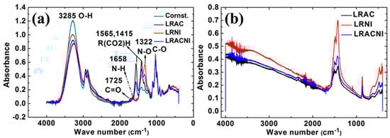
Figure 1.
FTIR spectra of (a) gel sample, and (b) dry powder. The acetyl in the LRAC demonstrates the reaction of cornstarch with acetates, disrupting gel formation.
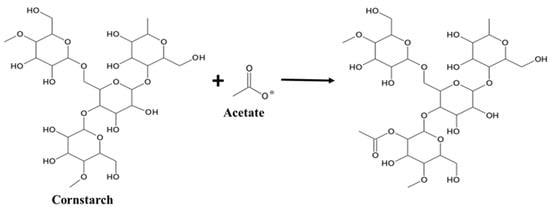
Figure 2.
Acetylation mechanism of cornstarch reaction with metal acetates.
C27H47O19OH + CH3OO−→C28H50O21 + OH−
This would change its ability to capsulate any particles formed. None of those peaks are present for the nitrate sample LRNI. The sample that has a mixture of acetate and nitrate (LRACNI) similarly shows a small ester acetyl peak near 1750 cm−1. Together, the FTIR results show that the cornstarch behaves differently in the synthesis with acetate and nitrate salts, acting as a capping agent on particles formed with nitrate salts. This provides evidence as to why there are different sizes of particles made with acetate and nitrate salts. Additionally, we can look for C–N peaks in the LRNI sample (around 1100 cm−1). Ideally, they should not be there, as the peaks for the cornstarch overlay directly on the nitrate sample. The results show that the cornstarch in the nitrate sample is unchanged and acts as a capping agent on its own.
For the dry powder, as shown in Figure 1b, we can also see there is an -OH peak in the acetate sample. If all of the -OH groups have been removed, the peak (near 3300 cm−1) should be small. This indicates that not only the surfactant properties are changing with acetylation, but the formed gel is likely different enough to change how the particles aggregate (e.g., H-bonding, in particular, disappears).
3.2. Thermal Analysis
Figure 3 shows the thermal analysis results of the dry powders of LRAC, LRNI, and LRACNI. The thermal behavior of all the samples shows almost a similar trend up to 250 °C. The 25–120 °C region corresponds to the weight loss of the physically absorbed water; there is no weight loss in the region between 125–250 °C. The reason would correspond to the decomposition of the acetate precursor with cornstarch, indicating their absence as they already were decomposed. However, the LRAC sample shows a quite different thermal behavior from the other two samples after 250 °C, as depicted in Figure 3a. The formation and dissolution of the metastable chelating complex are more likely to happen at 363 °C and 440 °C, respectively, while with water solvent, the formation occurred at 380 °C and 450 °C, respectively []. In addition, the desired product of Li1.2Mn0.5100Ni0.2175Co0.0725O2 formed at 466 °C, as indicated in Figure 1a. LRNI and LRACNI show three distinct weight loss regions during heat treatment as follows: liberation of NOx and COx gases between 250–329 °C, completion of the cornstarch-nitrate combustion process in the reaction region between 329–425 °C, and the final product formation between 425–490 °C, in particular, at 466 °C, as illustrated in Figure 3.
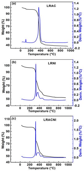
Figure 3.
Thermal analysis of cornstarch with (a) LRAC; (b) LRNI; and (c) LRACNI, showing the weight loss and the derivative of the weight loss curves.
One notable result from the thermal analysis of the three materials is that the weight loss of LRACNI is higher than LRNI and lower than LRAC, which reveals the strongest bond (N–O) of LRNI and the weakest bond of LRAC (acetate bond). The higher released energy from the breaking of the N–O bond in LRNI results in the evaporation of more organic components, which leads to reducing the weight loss in the subsequent heat treatment processes. Furthermore, the cornstarch-nitrate combination confirms what was explained earlier in Figure 1, which is that the cornstarch is a capping agent of nitrate-based particles, effectively preventing the formation of large particles. In addition, cornstarch plays a dual role in the synthesis, both as a gelling agent and as an exothermic combustible fuel. It was noted in this present study that the use of cornstarch had exhibited the same thermal behavior as in a previous report on the preparation of Li2MnO4 and LiCoO2 using cornstarch as a combustion-assisting component [].
3.3. Materials Compositions
An inductively coupled plasma mass spectrometry (ICP-MS) analyzer was used to confirm the concentrations of the forming LRAC, LRNI, and LRACNI materials. Table 1 shows the concentration of each element in the mole ratio. The results demonstrate good agreement between the nominal values for elements Mn, Ni, and Co. On the other hand, LRN1 exhibits a higher lithium loss of ~8.6% than LRAC at ~1.8% and LRACNI at 3%. This is mainly attributed to the higher agglomeration of acetate-based salt powder that could hinder Li loss by decreasing the surface area. On the contrary, the nitrate-based salts release NOx and COx gases resulting in more likely fluffy structure [] and increased outer surface area, leading to increased Li loss during preparation of the material.

Table 1.
ICP-MS data for LRAC, LRAC, and LRNI cathode materials.
3.4. Powder Morphology and Size
As can be seen from the Scanning Electron Microscopy (SEM) images in Figure 4a, LRAC powder has a particle size of~0.8 μm with rectangular prismatic nanorod and hexagonal nanorod particles. It is well known that the branched-type cornstarch forms gels with acetate, but the linear form usually reacts with the nitrate to release COx and NOx, forming a fluffy mass []. The fluffy mass in LRNI possesses a reduced particle size of~0.4 μm with spherical grains, as shown in Figure 4b. It is also evident from the SEM images that the presence of nitrate and acetate anions in LRACNI synthesis produces an intermediate particle size of~0.6 μm (Figure 4c).
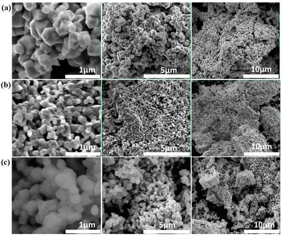
Figure 4.
Typical SEM images of (a) LRAC, (b) LRNI, and (c) LRACNI, at different magnifications, showing different particle sizes due to the different effects of cornstarch as a gelling agent.
3.5. XRD Structure Analysis
Figure 5a,b show the XRD patterns and local details of the LRAC, LRNI, and LRACNI compounds. As shown in Figure 5a, all the prepared samples possess a typical rhombohedral symmetry in space group Rm for layered phase LiMO2, and monoclinic symmetry in space group C2/m for Li2MnO3 [,,]. Additionally, the almost-identical structures of the prepared samples indicate that the initial precursor salts have no apparent effect on the crystalline structure. All the diffraction peaks could be indexed to the layered structure of the α-NaFeO2 type, except for the weak diffraction peaks between 20° and 25°, which are indexed to the effect of the superlattice monoclinic structure of Li2MnO3 []. The apparent splits of the (006)/(012) and (108)/(110) peaks for all the prepared samples demonstrate excellent crystallinity and well-defined layered structures for the synthesized materials [,]. From Figure 1b, the (003) peak first shifts to a higher angle using a pure nitrate content (LRNI), and then moves to a lower angle with pure acetate raw material (LRAC), which manifests the shrinking and expansion in lattice dimensions and confirms further what has been explained earlier in Figure 1.
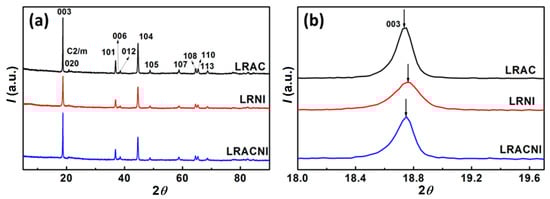
Figure 5.
XRD patterns of LRAC, LRNI, and LRACNI in the 2θ range of (a) 5°–90° and (b) 18°–19.7° for fine structures.
Lattice parameters of the samples were calculated using XRD data, and the results are listed in Table 2 The results show a slight increase in the lattice parameters and in nitrate-based materials, indicative of some lithium-ion electronegative vacancies generated to balance the loss of Li+ during the preparation steps. As shown in the ICP-MS results in Table 1, the lithium loss increases with increasing nitrate content, and LRNI has the most lithium-ion electronegative vacancies and LRAC the least. Accordingly, the lattice parameters increase with increasing nitrate contents. From Table 2, the lattice parameter ratio > 4.9 and the peak intensity ratio I(003)/I(104) > 1.2 suggest that a well-ordered hexagonal structure with good crystallinity and no undesirable cation mixing is present in all of the samples []. Compared with LRAC and LRNI, LRACNI shows the highest I(003)/I(104) value of 1.9351, implying the best cationic ordering among the three samples.
Table 2.
Lattice parameters of LRAC, LRNI, and LRACNI samples.
3.6. Electrochemical Characterizations
The 1st, 5th, 10th, and 30th charge/discharge tests for the LRAC, LRNI, and LRACNI materials were carried out in the potential range of 2.0–4.8 V at 0.1 C (1 C = 200 mA/g) as displayed in Figure 6. The 1st charge cycle shows two plateau regions. The first plateau results from the oxidation of Ni2+/Ni4+ and Co3+/Co4+ [,]. LRNI has a higher surface area (the reaction occurs on the surface), therefore, the plateau in LRNI is much longer than that in LRAC and LRACNI, meaning that LRNI provides a higher specific capacity. The second plateau region above~4.5 V is related to the activation of Li2MnO3 [,]. LRNI shows a higher activation of Li2MnO3, which is attributed to more reactive sites associated with the higher surface area of this sample, resulting in a higher transformation of the layered phase to the spinel phase. However, for LRACNI and LRAC, the oxidation reaction region of Li2MnO3 decreases, indicating that the larger particle size could minimize full phase transformation in the first cycle. Consequently, LRNI provides the highest initial charge/discharge capacity of 374.00/256.85 mAh/g, compared to 275.86/185.09 mAh/g and 338.52/248.32 mAh/g of LRAC and LRACNI, respectively. For the subsequent cycles, the plateau above~4.5 V disappeared entirely. This is attributed to irreversible Li loss in the first charge cycle accompanied by oxygen from lithium and transition metal layers in the form of Li2O [,].
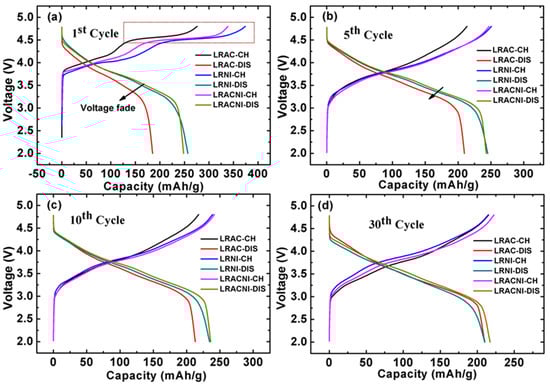
Figure 6.
(a) 1st; (b) 5th; (c) 10th; and (d) 30th charge/discharge curves for LRAC, LRNI, and LRACNI cathode materials.
The voltage fade of LRAC in the first discharge cycle is much greater than that of LRNI or LRACNI. However, for the 5th, 10th, and 30th cycles, this voltage fade decreases gradually, until it becomes overlapped with LRNI and slightly less than LRACNI. This noticeable voltage fade behavior could be attributed to the incomplete extraction of Li+ from the LRAC sample in the first discharge cycle, resulting in a low Li2MnO3 reaction region associated with high discharge voltage fade. The larger particle size can deter phase change, which in turn increases the charge/discharge specific capacity and working voltage over cycling []. Synthesizing intermediate-sized particles as in LRACNI delivers a high initial discharge capacity relative to LRAC and LRNI samples, as illustrated in Figure 6.
The electrochemical performances of the materials were further studied by cycling the cells at a current rate of 0.1 C as shown in Figure 7a. The coulumbic efficiencies were calculated as shown in Figure 7b. The results display different performance categories, which are mostly influenced by the particle size. The 1st/30th discharge capacities of LRAC, LRNI, and LRACNI were 185.09/210.25, 256.85/210.09, and 248.32/217.28 mAh/g, respectively. LRACNI shows the highest coulumbic efficiency in the first cycle of 73.35%, as compared to 67.1% and 68.7% for LRAC and LRNI, respectively. The higher reversible capacity of the LRACNI sample is mainly attributed to the lower cationic mixing of Ni+2 and Li+, which can affect Li+ diffusion during the intercalation/deintercalation processes. This could be argued by the highest I(003)/I(104) value among the three samples []. After the 1st cycle, the coulumbic efficiencies of the three tested samples show an almost symmetrical trend.
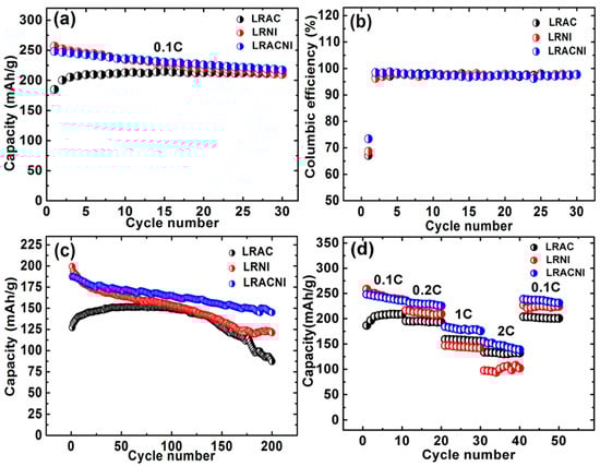
Figure 7.
(a) Discharge capacities at 0.1 C; (b) Coulumbic efficiency at 0.1 C; (c) Discharge capacities at 1 C; and (d) Rate capability at different current densities; of LRAC, LRNI, and LRACNI between 2.0–4.8 V.
The cells were discharged at 1 C (200 mA/g) with a 2.0–4.8 V voltage range for 200 cycles, as displayed in Figure 7c. The 1st/200th discharge cycles were 127.32/87.15 (68.45% capacity retention), 199.14/121.04 (60.78%), and 187.41/144.93 (77.33%), for LRAC, LRNI, and LRACNI, respectively. These results are consistent with the XRD results that suggest LRACNI has the best cationic ordering, as cationic mixing is the main reason of capacity deterioration over cycling. Figure 7d shows the rate performance of samples when they were discharged between 2.0–4.8 V. Due to the electrode polarization at high rates, the discharge capacities of the tested electrodes fade with increasing discharge current rates []. However, LRAC and LRACNI electrodes exhibit remarkably improved rate capabilities when compared to the LRNI electrode. Of the three tested electrodes, LRACNI exhibits the optimal rate performance up to 1 C, giving discharge capacities of 248.32, 235.63, and 184.33 mAh/g at 0.1, 0.2, and 1 C, respectively. This is clearly better than the LRAC sample (186.60, 195.48, and 159.29 mAh/g at 0.1, 0.2, and 1 C, respectively). This outstanding rate performance of the LRACNI electrode is mainly ascribed to the enlargement of Li+ diffusion channels. This is caused by the low cationic mixing of Ni2+ and Li+, which is favorable during the insertion/extraction of Li+ []. However, at 2 C, LRAC shows much better rate performance stability than LRACNI. The deterioration in rate capability of LRACNI at higher C rates can be mainly attributed to a thicker solid electrolyte interphase (SEI) layer that is associated with smaller particle size [].
To confirm the cycling performance of the synthesized materials, cyclic voltammetry (CV) was carried out within a potential range of 2.0–4.8 V at 0.1 mV/s scan rate for the initial ten cycles as displayed in Figure 8a–c. All three samples show distinctive CV curves of Li-rich cathode materials [,]. The first charge cycle shows two peaks. The one at~4.0 V corresponds to the oxidation of Ni2+/Ni4+ and Co3+/Co4+ in the layered phase []. The 2nd peak at~4.7 V is ascribed to the activation of Li2MnO3, which disappeared in subsequent cycles, indicating irreversible removal of Li+ in the form of Li2O from Li2MnO3 [,]. The corresponding cathodic peaks of Ni4+/Ni3+ and Co4+/Co3+ are observed at~4.25 V and~3.75 V, respectively. Interestingly, LRACNI exhibits smaller differences between anodic and cathodic peaks of 0.27 V and 0.17 V in the 1st and 10th cycles, respectively, compared to 0.29 V and 0.23 V and 0.31 V and 0.315 V of LRAC and LRNI at the 1st and 10th cycles, respectively. This result indicates that LRACNI has significantly better reversibility than the other samples, consistent with what was explained earlier for Figure 5 and Figure 7b. For LRAC and LRACNI, there are oxidation peaks at~3.25 V. These peaks gradually become more evident and shift to ~3.0 V over cycling. This oxidation peak is mainly attributed to a lithium deintercalation process from the Li2MnO3 layer [,], which explains the incomplete activation of the Li2MnO3 layer of these samples in the first cycle. On the other hand, there is no evidence for such a peak for LRNI, suggesting that LRNI suffers from capacity fading over cycling due to the total activation of Li2MnO3 in the first cycle. The cathodic peaks at~3.25 V are attributed to Mn4+/3+. The appearance of the~3.25 V peaks in the LRAC and LRACNI electrodes with noticeable developments over cycling, manifests a gradual increase in the capacity of this material over cycling. These results are consistent with the cycling performances shown in Figure 7.
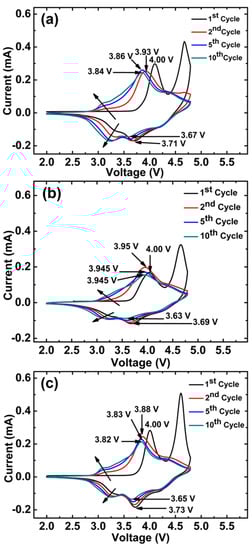
Figure 8.
Cycle voltammetries of (a) LRAC, (b) LRNI, and (c) LRACNI; at a scan rate of 0.1 mV/s, between 2.0–4.8 V.
Figure 9 shows the EIS spectra for LRAC, LRNI, and LRACNI electrodes after the 10th cycle in the frequency range from 0.05 Hz to 1 MHz. The measurements were carried out at the discharged state of 2.0 V and a scan rate of 0.1 mV/s. The Electrochemical Impedance Spectroscopy (EIS) measurement is necessary to show the electrochemical and kinetic characteristics of each electrode material. The high-frequency semicircles represent the solid electrolyte interface resistance (RSEI). LRACNI shows the lowest RSEI value of 45.23 Ω, compared to 54.11 Ω and 231.79 Ω for LRAC and LRNI, respectively. It is clearly revealed that a high surface area, associated with small particles of LRNI, gives the highest electrode-electron resistivity. It suggests that side reactions occur between the active material and the electrolyte, leading to a great increase in interfacial resistance [].
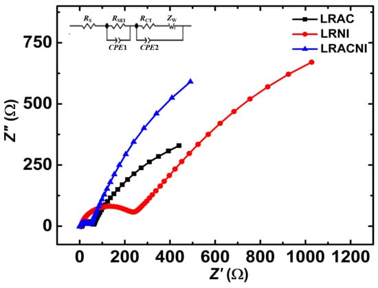
Figure 9.
EIS spectra for LRAC, LRNI, and LRACNI electrodes, after the 10th cycle.
It can be concluded from this study that mixing 50% (in moles) acetate-based salts with the same amount of nitrate-based salts can produce an effective cathode material, LRACNI, with much-improved cycling stability due to the reduction in the interfacial, electrochemical reaction activity between the electrode and electrolytes.
4. Conclusions
Metal acetate and nitrate salts were studied in the synthesis of lithium-rich Li1.2 Mn0.51Ni0.2175Co0.0725O2 cathode materials for lithium-ion batteries. It was found that metal nitrate salts produced the smallest particles that suffer rapid capacity fading. On the other hand, metal acetate salts produced the largest particles, attributed to that the gelling agent cornstarch can react with acetate anions, effectively disrupting gels in capping the particles. It was further demonstrated that when a mixture of metal acetate and nitrate salts are used, intermediate particle size was obtained. While the small particles in the powder from nitrate salts (LRNI) have the advantage of giving high initial charge/discharge capacity, the large particles from acetate salts (LRAC) can suppress the total phase change in the first cycle. It is the powders made from the mixed acetate and nitrate salts (LRACNI) with the intermediate particle size that show the best electrochemical performance. The LRACNI powder showed excellent capacity retention of 77.33% after 200 cycles at 1 C rate in the voltage range of 2.0–4.8 V, as compared to 68.45% and 60.78% capacity retention of LRAC and LRNI, respectively. Our results show that metal with different anions has a significant impact on the morphology and structure of the prepared materials in glycerol. Further studies on controlling the ratios of different metal salts used should lead to an optimal material in electrochemical performances. Furthermore, the use of renewable glycerol as a solvent in the synthesis of the battery materials promises an environmentally friendly process for materials synthesis.
Author Contributions
conceptualization, Y.X. and K.I.H.; methodology, K.I.H. and Y.X.; investigation, K.I.H.; writing—original draft preparation, K.I.H.; writing—review and editing, Y.X.; supervision, Y.X.; project administration, Y.X.; funding acquisition, Y.X.
Funding
This research was funded in part by the U.S. Department of Energy (under grant # DEEE0007282) and the University of Missouri. The APC was funded by University of Missouri.
Acknowledgments
The authors would like to thank Eric Bohannan for help with obtaining XRD results, Honglan Shi with ICP-MS analysis, Nathaniel E. Larm in the chemistry department and Fouad K. Alsammarraie in the Food Science for FTIR analysis. Khaleel Idan Hamad would like to thank the Higher Committee for Education Development in Iraq (HCED) for providing a scholarship.
Conflicts of Interest
The authors declare no conflict of interest.
References
- Goodenough, J.B.; Kim, Y. Challenges for Rechargeable Li Batteries. Chem. Mater. 2010, 22, 587–603. [Google Scholar] [CrossRef]
- Etacheri, V.; Marom, R.; Elazari, R.; Salitra, G.; Aurbach, D. Challenges in the development of advanced Li-ion batteries: A review. Energy Environ. Sci. 2011, 4, 3243–3262. [Google Scholar] [CrossRef]
- Nishi, Y. The development of lithium ion secondary batteries. Chem. Record. 2001, 1, 406–413. [Google Scholar] [CrossRef] [PubMed]
- Goodenough, J.B.; Park, K.-S. The Li-Ion Rechargeable Battery: A Perspective. J. Am. Chem. Soc. 2013, 135, 1167–1176. [Google Scholar] [CrossRef] [PubMed]
- Xu, B.; Qian, D.; Wang, Z.; Meng, Y.S. Recent progress in cathode materials research for advanced lithium ion batteries. Mater. Sci. Eng. R Rep. 2012, 73, 51–65. [Google Scholar] [CrossRef]
- Xu, J.; Dou, S.; Liu, H.; Dai, L. Cathode materials for next generation lithium ion batteries. Nano Energy 2013, 2, 439–442. [Google Scholar] [CrossRef]
- Whittingham, M.S. Lithium Batteries and Cathode Materials. Chem. Rev. 2004, 104, 4271–4302. [Google Scholar] [CrossRef] [PubMed]
- Thackeray, M.M.; Kang, S.-H.; Johnson, C.S.; Vaughey, J.T.; Benedek, R.; Hackney, S.A. Li2MnO3 -stabilized LiMO2 (M = Mn, Ni, Co) electrodes for lithium-ion batteries. J. Mater. Chem. 2007, 17, 3112–3125. [Google Scholar] [CrossRef]
- Ito, A.; Li, D.; Ohsawa, Y.; Sato, Y. A new approach to improve the high-voltage cyclic performance of Li-rich layered cathode material by electrochemical pre-treatment. J. Power Sources 2008, 183, 344–346. [Google Scholar] [CrossRef]
- Thackeray, M.M.; Johnson, C.S.; Vaughey, J.T.; Li, N.; Hackney, S.A. Advances in manganese- oxide ‘composite’ electrodes for lithium-ion batteries. J. Mater. Chem. 2005, 15, 2257–2267. [Google Scholar] [CrossRef]
- Lu, Z.; Dahn, J.R. Understanding the Anomalous Capacity of Li/Li[NixLi(1/3−2x/3)Mn (2/3−x/3)]O2 Cells Using In Situ X-Ray Diffraction and Electrochemical Studies. J. Electrochem. Soc. 2002, 149, A815–A822. [Google Scholar] [CrossRef]
- Johnson, C.S.; Kim, J.-S.; Lefief, C.; Li, N.; Vaughey, J.T.; Thackeray, M.M. The significance of the Li2MnO3 component in ‘composite’ xLi2MnO3 · (1 − x)LiMn0.5Ni0.5O2 electrodes. Electrochem. Comm. 2004, 6, 1085–1091. [Google Scholar] [CrossRef]
- Yu, H.; Wang, Y.; Asakura, D.; Hosono, E.; Zhang, T.; Zhou, H. Electrochemical kinetics of the 0.5Li2 MnO3 ·0.5LiMn0.42Ni0.42Co0.16O2 ‘composite’ layered cathode material for lithium-ion batteries. RSC Adv. 2012, 2, 8797–8807. [Google Scholar] [CrossRef]
- Zhang, H.Z.; Qiao, Q.Q.; Li, G.R.; Ye, S.H.; Gao, X.P. Surface nitridation of Li-rich layered Li(Li0.17Ni0.25Mn0.58)O2 oxide as cathode material for lithium-ion battery. J. Mater. Chem. 2012, 22, 13104–13109. [Google Scholar] [CrossRef]
- Armstrong, A.R.; Holzapfel, M.; Novák, P.; Johnson, C.S.; Kang, S.-H.; Thackeray, M.M.; Bruce, P.G. Demonstrating Oxygen Loss and Associated Structural Reorganization in the Lithium Battery Cathode Li[Ni0.2Li0.2Mn0.6]O2. J. Am. Chem. Soc. 2006, 128, 8694–8698. [Google Scholar] [CrossRef] [PubMed]
- Kang, S.-H.; Kempgens, P.; Greenbaum, S.; Kropf, A.J.; Amine, K.; Thackeray, M.M. Interpreting the structural and electrochemical complexity of 0.5Li2MnO3·0.5LiMO2 electrodes for lithium batteries (M = Mn0.5−xNi0.5−xCo2x, 0 ≤ x ≤ 0.5). J. Mater. Chem. 2007, 17, 2069–2077. [Google Scholar] [CrossRef]
- Johnson, C.S.; Li, N.; Lefief, C.; Thackeray, M.M. Anomalous capacity and cycling stability of xLi2MnO3 · (1 − x)LiMO2 electrodes (M = Mn, Ni, Co) in lithium batteries at 50 °C. Electrochem. Commun. 2007, 9, 787–795. [Google Scholar] [CrossRef]
- Manthiram, A.; Knight, J.C.; Myung, S.-T.; Oh, S.-M.; Sun, Y.-K. Nickel-Rich and Lithium-Rich Layered Oxide Cathodes: Progress and Perspectives. Adv. Energy Mater. 2016, 6, 1501010. [Google Scholar] [CrossRef]
- Liu, X.; Huang, T.; Yu, A. Surface phase transformation and CaF2 coating for enhanced electrochemical performance of Li-rich Mn-based cathodes. Electrochim. Acta 2015, 163, 82–92. [Google Scholar] [CrossRef]
- Lu, C.; Wu, H.; Zhang, Y.; Liu, H.; Chen, B.; Wu, N.; Wang, S. Cerium fluoride coated layered oxide Li1.2Mn0.54Ni0.13Co0.13O2 as cathode materials with improved electrochemical performance for lithium ion batteries. J. Power Sources 2014, 267, 682–691. [Google Scholar] [CrossRef]
- Wang, D.; Belharouak, I.; Ortega, L.H.; Zhang, X.; Xu, R.; Zhou, D.; Zhou, G.; Amine, K. Synthesis of high capacity cathodes for lithium-ion batteries by morphology-tailored hydroxide co-precipitation. J. Power Sources 2015, 274, 451–457. [Google Scholar] [CrossRef]
- Phadke, S.; Anouti, M. Effect of lithium salt concentration on the capacity retention of Lithium rich NMC cathodes. Electrochim. Acta 2017, 223, 31–38. [Google Scholar] [CrossRef]
- Huang, Z.-D.; Liu, X.-M.; Oh, S.-W.; Zhang, B.; Ma, P.-C.; Kim, J.J.-K. Microscopically porous, interconnected single crystal LiNi1/3Co1/3Mn1/3O2 cathode material for Lithium ion batteries. Mater. Chem. 2011, 21, 10777–10784. [Google Scholar] [CrossRef]
- Zhang, C.; Yang, P.; Dai, X.; Xiong, X.; Zhan, J.; Zhang, Y. Synthesis of LiNi1/3Co1/3Mn1/3O2 cathode material via oxalate precursor. Trans. Nonferrous Met. Soc. China 2009, 19, 635–641. [Google Scholar] [CrossRef]
- He, P.; Wang, H.; Qi, L.; Osaka, T. Electrochemical characteristics of layered LiNi1/3Co1/3Mn1/3O2 and with different synthesis conditions. J. Power Sources 2006, 160, 627–632. [Google Scholar] [CrossRef]
- Gangulibabu; Bhuvaneswari, D.; Kalaiselvi, N. Comparison of corn starch-assisted sol–gel and combustion methods to prepare LiMnxCoyNizO2 compounds. J. Solid State Electrochem. 2013, 17, 9–17. [Google Scholar] [CrossRef]
- Hamad, K.I.; Liao, J.-Y.; Smith, T.W.; Xing, Y. Synthesis of Layered LiMn1/3Ni1/3Co1/3O2 Oxides for Lithium-Ion Batteries using Biomass-Derived Glycerol as Solvent. Energy Technol. 2017, 6, 710–717. [Google Scholar] [CrossRef]
- Hamad, K.I.; Xing, Y. Effect of Cobalt and Nickel Contents on the Performance of Lithium Rich Materials Synthesized in Glycerol Solvent. J. Electrochem. Soc. 2018, 165, A2470–A2475. [Google Scholar] [CrossRef]
- Ozawa, K.; Nakao, Y.; Mochiku, T.; Cheng, Z.; Wang, L.; Iwai, H.; Tsuchiya, Y.; Fujii, H.; Igawa, N. Electrochemical Characteristics of Layered Li1.95Mn0.9Co0.15O3 (C2/m) as a Lithium-Battery Cathode. J. Electrochem. Soc. 2012, 159, A300–A304. [Google Scholar] [CrossRef]
- Yu, S.-H.; Yoon, T.; Mun, J.; Park, S.; Kang, Y.-S.; Park, J.-H.; Oh, S.M.; Sung, Y.-E. Continuous activation of Li2MnO3 component upon cycling in Li1.167Ni0.233Co0.100Mn0.467Mo0.033O2 cathode material for lithium ion batteries. J. Mater. Chem. A 2013, 1, 2833–2839. [Google Scholar] [CrossRef]
- Hong, J.; Seo, D.-H.; Kim, S.-W.; Gwon, H.; Oh, S.-T.; Kang, K. Structural evolution of layered Li1.2Ni0.2Mn0.6O2 upon electrochemical cycling in a Li rechargeable battery. J. Mater. Chem. 2010, 20, 10179–10186. [Google Scholar] [CrossRef]
- Guan, J.; Hanna, M.A. Extruding Foams from Corn Starch Acetate and Native Corn Starch. Biomacromolecules 2004, 5, 2329–2339. [Google Scholar] [CrossRef] [PubMed]
- Kalyani, P.; Kalaiselvi, N.; Muniyandi, N. A new solution combustion route to synthesize LiCoO2 and LiMn2O4. J. Power Sources 2002, 111, 232–238. [Google Scholar] [CrossRef]
- Wang, Y.X.; Shang, K.H.; He, W.; Ai, X.P.; Cao, Y.L.; Yang, H.X. Magnesium-Doped Li1.2[Co0.13Ni0.13Mn0.54]O2 for Lithium-Ion Battery Cathode with Enhanced Cycling Stability and Rate Capability. ACS Appl. Mater. Interf. 2015, 7, 13014–13021. [Google Scholar] [CrossRef]
- Song, B.; Lai, M.O.; Lu, L. Influence of Ru substitution on Li-rich 0.55Li2MnO3·0.45LiNi1/3Co1/3Mn1/3O2 cathode for Li-ion batteries. Electrochim. Acta 2012, 80, 187–195. [Google Scholar] [CrossRef]
- Zheng, J.; Wu, X.; Yang, Y. Improved electrochemical performance of Li[Li0.2Mn0.54Ni0.13Co0.13]O2 cathode material by fluorine incorporation. Electrochim. Acta 2013, 105, 200–208. [Google Scholar] [CrossRef]
- Xu, G.; Xue, Q.; Li, J.; Li, Z.; Li, X.; Yu, T.; Li, J.; Wang, X.; Kang, F. Understanding the enhanced electrochemical performance of samarium substituted Li[Li0.2Mn0.54−xSmxCo0.13Ni0.13]O2 cathode material for lithium ion batteries. Solid State Ion. 2016, 293, 7–12. [Google Scholar] [CrossRef]
- He, W.; Yuan, D.; Qian, J.; Ai, X.; Yang, H.; Cao, Y. Enhanced high-rate capability and cycling stability of Na-stabilized layered Li1.2[Co0.13Ni0.13Mn0.54]O2 cathode material. J. Mater. Chem. A 2013, 1, 11397–11403. [Google Scholar] [CrossRef]
- Liu, X.; Liu, J.; Huang, T.; Yu, A. CaF2-coated Li1.2Mn0.54Ni0.13Co0.13O2 as cathode materials for Li-ion batteries. Electrochim. Acta 2013, 109, 52–58. [Google Scholar] [CrossRef]
- Lu, Z.; Beaulieu, L.Y.; Donaberger, R.A.; Thomas, C.L.; Dahn, J.R. Synthesis, Structure, and Electrochemical Behavior of Li [NixLi1/3−2x/3Mn2/3−x/3]O2. J. Electrochem. Soc. 2002, 149, A778–A791. [Google Scholar] [CrossRef]
- Song, B.; Liu, Z.; Lai, M.O.; Lu, L. Structural evolution and the capacity fade mechanism upon long-term cycling in Li-rich cathode material. Phys. Chem. Chem. Phys. 2012, 14, 12875–12883. [Google Scholar] [CrossRef] [PubMed]
- Kim, J.; Fulmer, P.; Manthiram, A. Synthesis of LiCoO2 cathodes by an oxidation reaction in solution and their electrochemical properties. Mater. Res. Bull. 1999, 34, 571–579. [Google Scholar] [CrossRef]
- Chen, M.; Chen, D.; Liao, Y.; Zhong, X.; Li, W.; Zhang, Y. Layered Lithium-Rich Oxide Nanoparticles Doped with Spinel Phase: Acidic Sucrose-Assistant Synthesis and Excellent Performance as Cathode of Lithium Ion Battery. ACS Appl. Mater. Interfaces 2016, 8, 4575–4584. [Google Scholar] [CrossRef] [PubMed]
- Jo, M.; Hong, Y.-S.; Choo, J.; Cho, J. Effect of LiCoO2 Cathode Nanoparticle Size on High Rate Performance for Li-Ion Batteries. J. Electrochem. Soc. 2009, 156, A430–A434. [Google Scholar] [CrossRef]
- Koga, H.; Croguennec, L.; Ménétrier, M.; Douhil, K.; Belin, S.; Bourgeois, L.; Suard, E.; Weill, F.; Delmas, C. Reversible Oxygen Participation to the Redox Processes Revealed for Li1.20Mn0.54Co0.13Ni0.13O2. J. Electrochem. Soc. 2013, 160, A786–A792. [Google Scholar] [CrossRef]
- Boulineau, A.; Simonin, L.; Colin, J.-F.; Bourbon, C.; Patoux, S. First Evidence of Manganese–Nickel Segregation and Densification upon Cycling in Li-Rich Layered Oxides for Lithium Batteries. Nano Lett. 2013, 13, 3857–3863. [Google Scholar] [CrossRef]
- Yabuuchi, N.; Yoshii, K.; Myung, S.-T.; Nakai, I.; Komaba, S. Detailed Studies of a High-Capacity Electrode Material for Rechargeable Batteries, Li2MnO3−LiCo1/3Ni1/3Mn1/3O2. J. Am. Chem. Soc. 2011, 133, 4404–4419. [Google Scholar] [CrossRef]
- Zheng, J.M.; Zhang, Z.R.; Wu, X.B.; Dong, Z.X.; Zhu, Z.; Yang, Y. The Effects of AlF3 Coating on the Performance of Li[Li0.2Mn0.54Ni0.13Co0.13]O2 Positive Electrode Material for Lithium-Ion Battery. J. Electrochem. Soc. 2008, 155, A775–A782. [Google Scholar] [CrossRef]
- Zheng, J.M.; Wu, X.B.; Yang, Y. A comparison of preparation method on the electrochemical performance of cathode material Li[Li0.2Mn0.54Ni0.13Co0.13]O2 for lithium ion battery. Electrochim. Acta 2011, 56, 3071–3078. [Google Scholar] [CrossRef]
© 2019 by the authors. Licensee MDPI, Basel, Switzerland. This article is an open access article distributed under the terms and conditions of the Creative Commons Attribution (CC BY) license (http://creativecommons.org/licenses/by/4.0/).