Review

Strategies and Challenge of Thick Electrodes for Energy Storage: A Review

1
Clean Energy Automotive Engineering Center and School of Automotive Studies, Tongji University, Shanghai 201804, China
2
China Shenhua Coal to Liquid and Chemical Shanghai Research Institute, Shanghai 201108, China
3
Department of Electrical Engineering, University at Buffalo, The State University of New York, Buffalo, NY 14260, USA
*
Authors to whom correspondence should be addressed.
Batteries 2023, 9(3), 151; https://doi.org/10.3390/batteries9030151
Submission received: 18 December 2022 / Revised: 14 February 2023 / Accepted: 24 February 2023 / Published: 27 February 2023

Abstract

:
In past years, lithium-ion batteries (LIBs) can be found in every aspect of life, and batteries, as energy storage systems (ESSs), need to offer electric vehicles (EVs) more competition to be accepted in markets for automobiles. Thick electrode design can reduce the use of non-active materials in batteries to improve the energy density of the batteries and reduce the cost of the batteries. However, thick electrodes are limited by their weak mechanical stability and poor electrochemical performance; these limitations could be classified as the critical cracking thickness (CCT) and the limited penetration depth (LPD). The understanding of the CCT and the LPD have been proposed and the recent works on breaking the CCT and improving the LPD are listed in this article. By comprising these attempts, some thick electrodes could not offer higher mass loading or higher accessible areal capacity that would defeat the purpose.

1. Introduction

Over the past few decades, lithium-ion batteries (LIBs) have attracted more attention as energy storage systems (ESSs) due to the drive for a greener future. LIBs are electrochemical ESSs that supply energy by electrochemical reactions occurring in porous electrodes. The introduction of LIBs into vehicles has required more demands for advanced batteries. A typical areal capacity for hybrid electrical vehicles (HEVs) is about 2 mAh·cm−2, while for typical electrical vehicles (EVs), it is 4 mAh·cm−2 for state-of-the-art LIBs [1]. Energy-to-weight ratio is a critical issue for ESSs, and a battery-level specific energy of ~225 Wh·kg−1 is widely accepted; it combines the weight and driving mileage for EVs [2]. To offer competitive advantages for EVs in market, the US Department of Energy (US DOE) and the Advanced Battery Consortium (USABC) held that the EVs should provide a range of at least 500 km, while batteries as ESSs need to possess high energy density of approximately 235 Wh·kg−1 and 500 Wh·L−1 at battery pack level [3,4].
For a greener future, the China Society of Automotive Engineers (CSAE) with the guidance from the Ministry of Industry and Information Technology of China (China IIT) publishes the Technology Roadmap of Clean and New Energy Vehicles 2.0. In addition, a higher demand of 500 Wh·kg−1 is proposed for advanced batteries for EVs in 2035 [5]. The US DOE organized a Battery 500 Consortium that aims to achieve battery energy above 500 Wh·kg−1, and some feasible strategies (see Figure 1a) are given for lithium metal batteries. In general, advanced strategies proposed to obtain high energy storage systems include: (1) to study the new electrochemical energy storage mechanisms [6]; (2) to broaden the cell potential window [7]; (3) to develop electrode materials with high specific capacity [8]; and (4) to design electrodes with high mass loading [9]. There are lots of studies that focus on developing next-generation high-energy batteries, such as Li-oxygen and Li-sulfur batteries. A high energy density lithium-oxygen battery based on a reversible four-electron conversion to lithium oxide was reported [6]. However, most studies have focused on energy density on materials level while the specific energy density of the represented battery packs is nearly four times smaller than the energy density on the material level (Figure 1b) [10]. Much non-active but indispensable components are introduced into batteries due to the need for its operation and management. Therefore, the improvement on the material or electrode level could not completely transferred to the battery level. Narrowing the gap in specific energy density between the material layer and the battery layer brings a brighter prospect for improving the battery energy density. The fourth path of this paper is based on this idea. Furthermore, the first three ways make efforts on the material or electrode level and need to put much energy on new mechanisms while the fourth path does not. Additionally, the fourth path could further improve energy density on the battery pack level based on the first three ways.
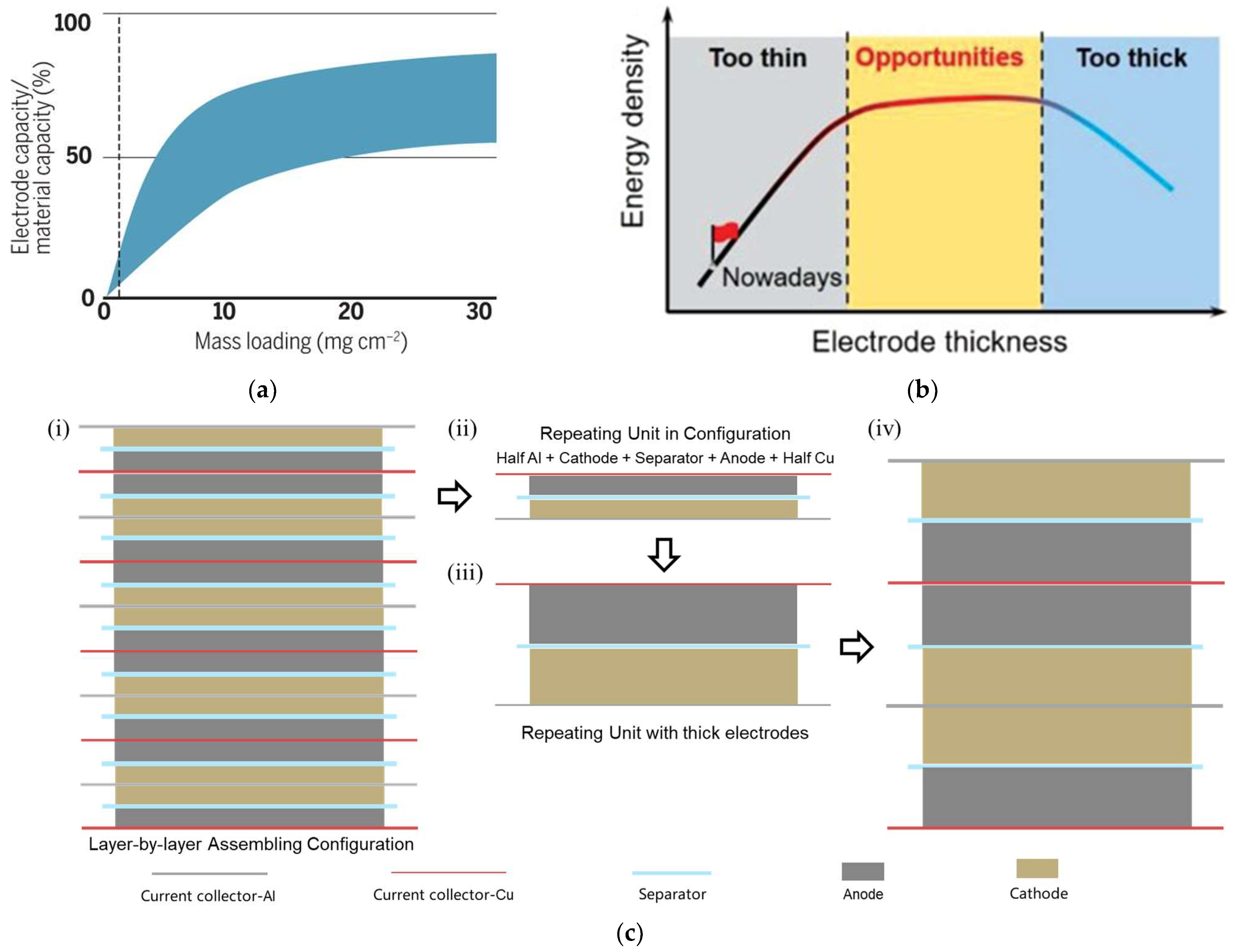
The fourth path to design electrodes with high mass loading is thick electrodes. The principle of thick electrodes design is that higher mass loading could decrease the share of non-active materials like current collectors and separators. However, it does not mean that the thicker the electrodes’ thickness the higher battery energy density. Figure 2a gives the advantage of thick electrodes, and the trend of curves supports that point. To further vividly explain this principle, taking the commercial laminated batteries for example (see Figure 2b), a repeating unit that contains electrode materials and current collectors and separators could be extracted. When using thick electrodes to replace the conventional electrodes in the repeating unit, the ratio of non-active materials in batteries is significantly decreased. The strategy of thick electrodes is to minimize the use of non-active materials to improve the battery energy density. Additionally, from Figure 2b, the use of non-active materials in batteries constructed by thick electrodes is already too low, which means that there is not more space for improving battery energy density from increasing electrode thickness. It is agreed with the second half curves in Figure 2a. Therefore, there is an optimal interval for the thickness or mass loading of the electrodes, as shown in Figure 2c. However, the concrete values are related various factors and not given.
In presently commercial LIBs, the thickness of electroactive components including the cathode and the anode are both limited between 50 and 100 μ m [14,15]. The design of thick electrodes is not a novel strategy, and its application is restricted by two serious obstacles: weak mechanical stability in production and poor electrochemical performance in working. It has been acknowledged in academia that there are two critical thickness for battery electrodes with high mass loading. One is the critical cracking thickness (CCT) about mechanical stability [16,17,18,19]; the other is the limited penetration depth (LPD) for electrolyte transport in the electrode [2,20,21,22].
In past years, much of the studies were devoted to new electrode design with high mass loading to boost the development of LIBs. To overcome the limitations of CCT, the plentiful works draw the support of three-dimensional frameworks to offer mechanical stability [9,23,24,25,26,27]. Electrodes with a thickness up to 850 μ m and an aerial mass of 55 mg·cm−2 have been constructed with the aid of wood templates [28]. For improving the limitation of LPD, to construct the ordered pores to decrease tortuosity is the most popular choice [29,30,31]. Thickness-independent electrodes constructed by vertical alignment of two-dimensional flakes could enable directional ions transport [32].
It is noteworthy that the limitations of ion diffusion in the liquid electrolyte deteriorate the rate capabilities of thick electrode design [2,33]. Therefore, introducing thick electrode design into all-solid-state lithium batteries (ASSLBs) could be helpful due to the uniform transference number of inorganic solid electrolytes [34]. Moreover, the current ASSLBs are produced by expensive and multi-step processes based on thin-layer-deposition techniques, and much efforts have been invested in increasing electrode thickness [35]. The combination of the two concepts could offer higher energy density and power density for lithium batteries. Hong et al. developed a new solvent-free dry technique to produce thick electrodes for ASSLBs which uses a Li+-conducting ionomer as a binder to form fibrous linear binding [36].
This paper will describe and discuss the latest advances in thick, porous electrodes from various perspectives, including the understanding of the two critical thicknesses, breakthroughs in the two critical thicknesses, and the relevant comparison between these studies.

2. The Challenge of Thick Electrodes

To obtain high energy density of 500 Wh·kg−1 for advanced batteries is the shared goal for China and US governments where are the largest automotive markets in the world. The Battery 500 Consortium proposed pathways to 500 Wh·kg−1 practical cells and an essential requirement is increasing the cathode thickness [11]. LIBs constructed by thick electrodes with high mass loading can benefit both vehicular range and unit cost in the application for EVs [37,38]. The superiority of thick electrodes design has been discovered formerly and the electrode thickness has been increased to over 100 μ m in commercial batteries. Therefore, there must be some problems hindering the realization of thicker electrodes.

2.1. The Critical Cracking Thickness (CCT)

During the drying of wet films, cracks were observed in diverse systems such as desiccated soil, concrete casting, ceramics slips and model colloidal dispersions [39,40]. Figure 3a give the diagram about the drying process [41]. It has been widely accepted that the capillary stresses during drying process are the cause of cracking formation [16,42,43,44]. When the slurry containing suspended particles is dried, capillary stresses are generated between particles in the air–solvent interface. If the particles are soft, they can remove stresses. However, in reverse case, the stresses are released by cracks formation when the particles are hard [16].
It has been observed that the CCT would increase with the increase of particle size and be not affected by the drying speed [16,19,41]. It is noteworthy that lower drying speed has positive effects on the fracture toughness but not the film thickness [43]. It has also proven that the drying rate actually has no impact on the CCT but crack size [45]. Additionally, decreasing film thickness and increasing particle shear modulus would increase the critical capillary pressure for cracking formation. Singh et al. analyzed the influencing factors of the capillary stresses and established a formula about the CCT:
h m a x = 0.41 G M r c p R 3 2 γ 1 / 2
where h m a x is the CCT, G is the shear modulus of the particles, M is the coordination number, r c p is the particle volume fraction at random close packing, R is the particle radius, and γ is the air–solvent interfacial tension [16].
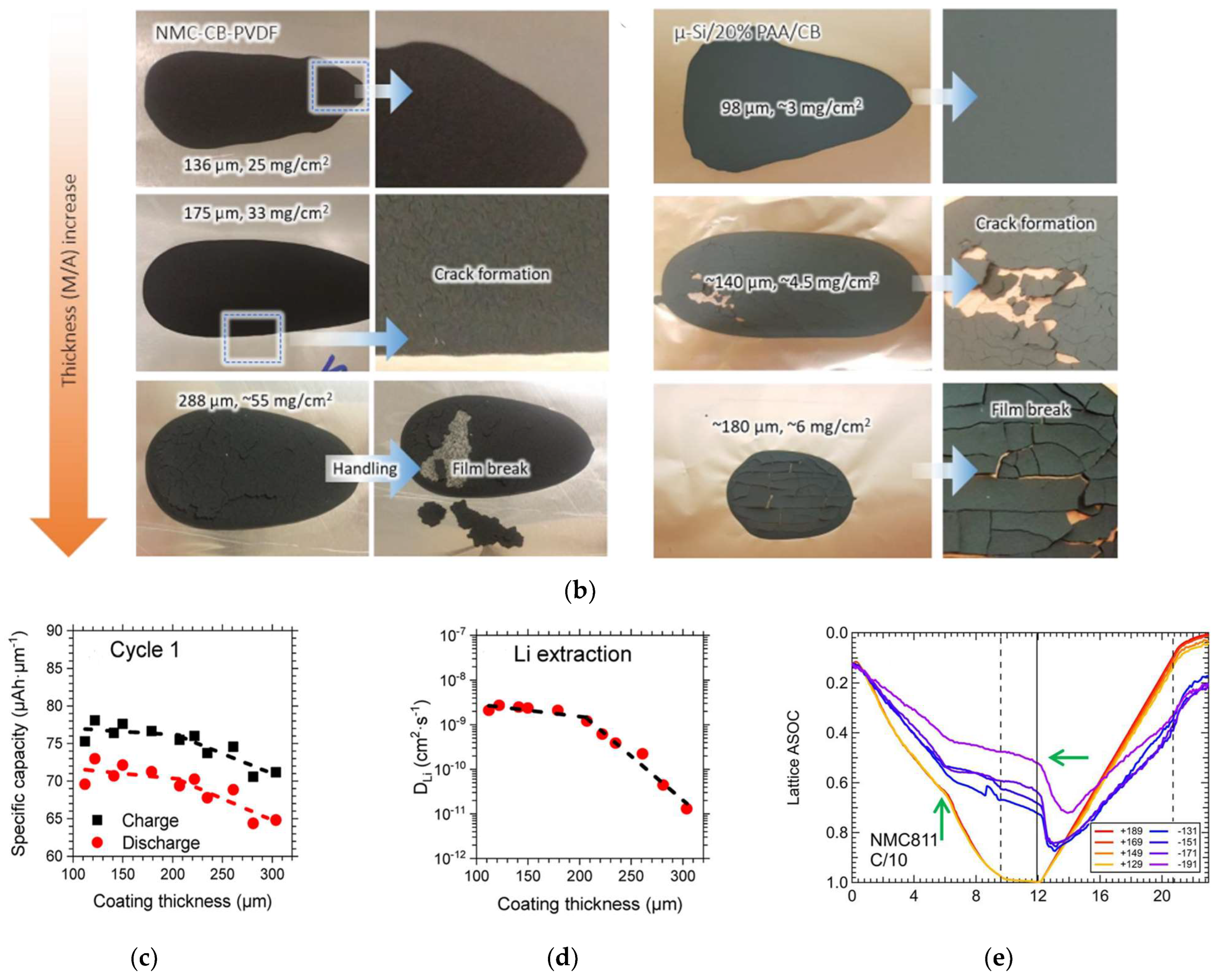
The traditional technology in electrode manufacture is to mix active materials with conductive additives and binders in organic solvents, and then to coat this slurry on current collectors like Al or Cu film. Additionally, a requisite step in this manufacture is to evaporate the solvents. The cracks also have been observed on battery electrodes, cracks were generated in NMC electrodes (NMC811:PVDF:CB = 90:5:5, wt.%) at a thickness above 175 μ m and any crack-free μ-Si electrodes (μ-Si:PAA:CB = 80:10:10, wt. %) could not be fabricated at a thickness above 100 μ m , as depicted in Figure 3b [46].

2.2. The Limited Penetration Depth (LPD)

High mass loading electrodes would increase the thickness of electrode films, which increases the diffusion distance of charges in electrodes. In the electrochemical process, the longer the charge diffusion distance, the lower the mass transfer efficiency [21]. Additionally, due to the sluggish ions transport kinetics, not all active materials in thick electrodes could be used in high C-rates. It has been proven that the limited diffusion of Li+ inside the porous electrode leads to the under-utilization of the active material [14,47,48,49].
When the LPD is greater than the designed electrodes thickness, mass transport in the electrolyte would not be the limited factors of the full utilization of active materials in electrodes [2]. To balance the migration of anions that do not participate in the electrochemical process, a lithium salt concentration gradient would form: that is what the LPD means [20]. The LPD is in inverse proportion to C-rates and tortuosity [22]. Additionally, a simple analytical equation for the LPD for electrolyte transport in the electrode is given:
L d = ε T D 0 c 0 F 1 t + I
where L d is the LPD, ε is the porosity of the electrode, T is the tortuosity factor of the pore matrix, D 0 is the diffusion coefficient of the lithium salt species in the electrolyte, c 0 is the initial concentration of electrolyte, t + is the transference number of Li+, I is the applied current density and F is the Faraday constant [2].
From experiments on NMC622, electrodes with different thicknesses, their specific capacities at C/50 rate were obtained and these values were normalized by their coating thickness [47]. An obvious turn at ~200 μ m was shown in the plot of the normalized capacity as the function of thickness, as shown in Figure 3c. Moreover, the lithium diffusion coefficient (DLi+) that calculated from GITT is a related parameter of Li+ diffusion behavior. The same turn at ~200 μ m were observed in the plot of DLi+ as the function of thickness (see Figure 3d). Additionally, the operando studies about the depth-dependent inhomogeneity are supported in this suspect, as shown in Figure 3e [50]. The same result has been proposed that the maximum film thickness limited by ions diffusion is approximately 200 μ m [32].
The ESSs for EVs are required in excellent performance in terms of energy and power. To fabricate battery electrodes with high mass loading needs to break the limit of the CCT, and the LPD is the obstacle that stands in the way of battery electrodes with high accessible areal capacity. According to the understanding of the CCT and the LPD, various ways have been developed to solve the problems.

3. Strategies for Increasing Electrode Thickness

Making thick electrodes a reality needs to break the limitations of CCT and LPD. Additionally, how to fabricate crack-free electrodes is the first concern, which means the solution could be two-step or one-step. The two-step solution is to solve those two problems separately, for example, a thick and free-standing electrode was constructed with two-dimensional nanomaterials that breaks the CCT and then a laser drilling technique was adopted to fabricate a micro-hole array in this electrode to increase the LPD [51]. The one-step solution is to solve those two problems simultaneously. For example, the ultra-thick electrodes made of wood formwork improve the mechanical stability of the frame. Additionally, the gap between the active materials and the carbon frames improve the diffusion kinetics during the drying process [52].

3.1. Increasing the CCT

From the formation mechanism, the cause of cracking is generated stresses during the drying process [16,19,41], and even is the traditional technology (the wet-slurry casting technology) from a higher vision. Therefore, there are three strategies to construct thicker electrodes. One is making efforts to decrease the generated stresses during the drying process, and another is using three-dimensional (3D) frameworks to offer mechanical stability while the other is taking new manufacture technologies beyond the traditional technology.

3.1.1. Decreasing Generated Stresses

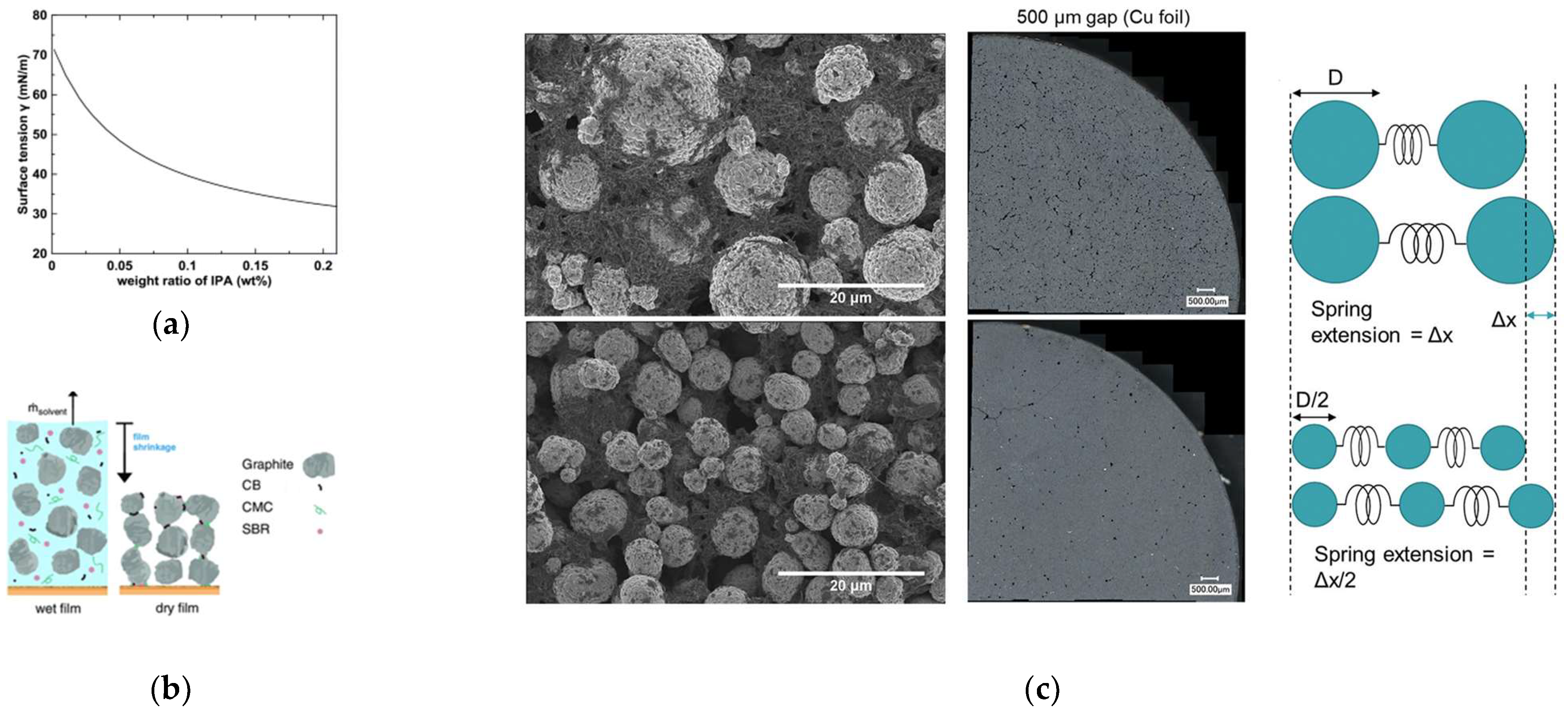
According to h m a x ~(1/γ)1/2 from Equation (1), the CCT could be improved by decreasing the surface tension. Thus, making efforts to decrease the surface tension is a straightforward method to alleviate or eliminate cracks. According to this point, Du et al. have successfully constructed a NMC532 electrode with areal loading above 25 mg·cm−2 (~4 mAh·cm−2) by introducing isopropyl alcohol (IPA) into aqueous solvent systems to decrease the surface tension, as shown in Figure 4a [41].
As shown in Figure 4b, the remaining particles are forced to fill a certain ratio of the formed void when the solvent is evaporating during the drying process. Additionally, cracking would occur when above a certain value. Therefore, the other way to reduce mechanical stresses is to reduce the amount of solvent which needs to be inevitably evaporated during drying process [44]. By increasing the solid content of the electrode slurry with using a new binder system to 65 wt.%, crack-free NMC111 electrodes have been constructed with an active mass loading of up to 60 mg·cm−2 and an average dry film thickness of (322 ± 9) μm [44].
Moreover, the observed results of NMC electrodes with different particle sizes are contrary to the estimate of h m a x ~R3/2 [53]. There is no contradiction, since the stresses are removed by the particles themselves when particles are soft, or by cracks when particles are hard. Additionally, there are more than one kind of particle in the electrode slurry. The NMC particles are hard, so the stresses are released by softer binders and conductive additives and even cracks. Additionally, a simple ball and spring model is given in Figure 4c, to reduce the size of active particles, which would decrease stresses in binders and conductive additives. Therefore, the formation of cracks was reformed when NMC811 particles of smaller size were used.

3.1.2. Utilizing 3D Frameworks

The mechanical stability of thick electrodes could draw support from 3D frameworks. Several thick and ultra-thick electrodes have been successfully fabricated with the aid of carbon frameworks [9,23,24,25,27], metal foams [15,54,55,56], and 3D conductive textile [57]. Besides, some 3D frameworks could offer convenient ion and electron channels to improve the limited diffusion kinetics due to the increased thickness.
Carbon nanotubes (CNT) and carbon nanofibers (CNF) are easy to form crosslinked networks and provide features as both binders and conductive additives. Park et al. constructed a high-performance electrode with the thickness of up to 800 μ m through segregated CNT networks, as shown in Figure 5a [46]. Due to the improved mechanical robustness through these networks, the extremely thick electrodes could be constructed. With the help of graphite fibers (GF) bonded with pyrolytic carbon (PC) and graphite nanoplatelets (GNP), an ultra-thick electrode with the thickness of 17 mm performed the reversible capacity of 11.63 mAh·cm−2 (as shown in Figure 5b) [24]. Additionally, some carbon networks could undertake the functions of binders and conductive additives. It may be profitable for decreasing the ratio of non-active materials in battery electrodes.
Additionally, the adhesion properties between the active material and traditional current collectors are constant when increase the mass loading of electrodes, so the possibility of delamination at the current-collector/active-material interface became larger. 3D current collectors could provide greater adhesion than the foil-type current collectors [54]. Thicker electrodes could be constructed when all particles are not more than 50 μ m from the nearest current collector. Metal foams have attracted more attention since they are the most suitable to introduce into the slurry casting process to fabricate electrodes. A graphite electrode was constructed with the thicknesses of 0.6 and 1.2 mm by using Cu foams as the current collector [15]. Additionally, Yang et al. fabricated a 450 μ m thick graphene electrode with mass loading of 10~15 mg·cm−2 by using Al foams [55].
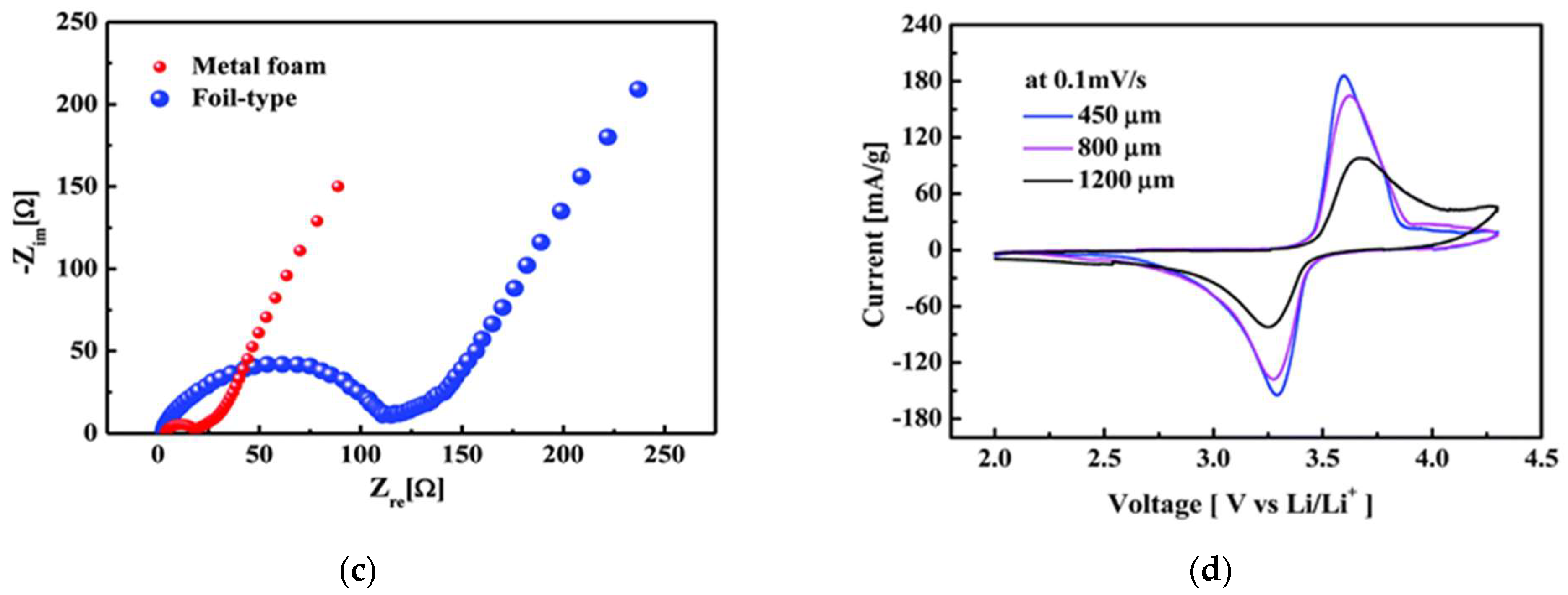
The 3D current collector also could improve kinetics of electrodes. From the comparison of foam-collector-type and foil-collector-type electrodes with similar mass loading of active materials, the charge transfer resistance was seven times less for the foam than for the foil, at values of 15 and 110 Ω (as shown in Figure 5c) [54], respectively. Furthermore, by comparing the cyclic voltametric curves for the cells using different sizes of metal foams, as shown in Figure 5d, a remarkable result was that the peak became lower and wider for the cell using 1200 μ m size of metal foams [56]. It indicated that using a 3D current collector to fabricate electrodes could settle mechanical, but not completely electrochemical, problems in thicker electrodes.
Other 3D frameworks are also used to fabricated thick electrodes. The 3D conductive textiles have been introduced batteries electrodes due to its stable potential range in organic electrolyte and electrodes have been fabricated with a thickness of ~600 μ m through 3D conductive textiles, which are 8–12 times higher of those on metal collector [57].

3.1.3. Taking New Technology

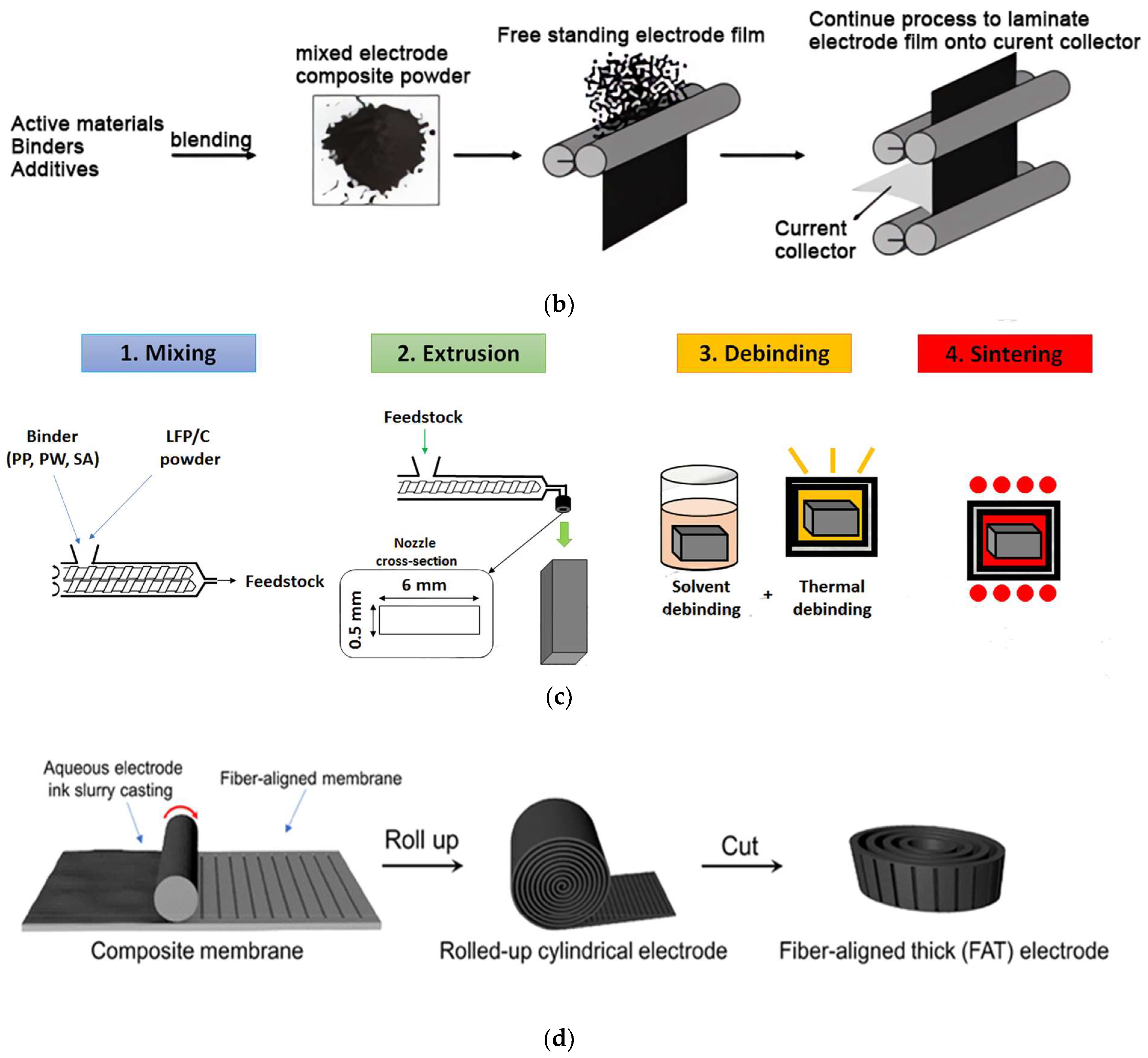
Since the cracks occur during drying process, taking some manufacture technologies without the evaporation process are possible ways to construct crack-free thick electrodes. Some technologies have been successfully introduced into battery electrodes like spraying [58,59,60], sintering [61], 3D printing [62,63,64,65], powder extrusion moulding (PEM) [66,67,68] and dry powder coating [69,70]. The solvent-free process is an ideal alternative solution to replace the wet slurry casting process. The related stresses generated during the drying process would no longer be considerations. Moreover, manufacture costs would be cut as the elimination of using and removing solvents.
A solvent-free technology is spray deposition that has been used in coating industries for over 30 years to create functional paints. Recently, this technology has been introduced into producing battery electrodes. The main processes of this technology are mixing, dry-spraying and hot-pressing. Figure 6a gives the optimized technology for using in battery electrodes. The fabricated LTO electrode has interconnected particles that facilitate electron and ion transport via shortened pathways within the electrodes [59]. Additionally, the film thickness could be controlled just by adjusting the spraying time [58].
Another solvent-free technology is dry-coating technology that does not introduce any solvents into the craft, as shown in Figure 6b. This technology maintains a liquid-free state in the full process from the raw materials to finished products. Free-standing electrodes with thicknesses between 50 microns to about 1 mm could be easily fabricated by this craft. It has been proven that the bonding strength between dry-deposited particles and current collectors could be greater than slurry-cast electrodes [70].
PEM is a cost-effective manufacturing method to produce battery electrode. The main steps of PEM are mixing, extrusion, de-binding and sintering, as shown in Figure 6c. Thick electrodes constructed by PEM technology shows better mechanical properties than alternative technologies [66]. The Li4Ti5O12 (LTO) anodes and the LiFePO4 (LFP) cathodes have been produced with the thickness as high as 500 μ m through this method [66,67]. Additionally, a LIB was assembled with this LTO anode and this LFP cathode and possessed mass loading of ~100 mg·cm−2 that is better than the current one [68]. Just as important, this technology is also an environmentally friendly technology for electrode manufacturing.
Due to the low-cost and simple manufacturability, extrusion-based 3D printing is a potential craft for electrode fabrication. The thickness of thick electrodes could be well controlled thanks to the layer-by-layer additive technique [71]. Sun et al. constructed an ultra-thick LTO electrode by using 3D printing with the thickness of 1500 μ m [62]. Additionally, 3D-printed electrodes with highly interconnected networks could offer ion- and electron-transport paths, which indicated a better electrochemical performance [63].
Additionally, a new design called fiber-aligned thick electrodes has been used to construct thick electrodes. The composite membrane contained aligned carbon fibers that could provide low tortuosity, high conductivity, and mechanically strong features for high mass loading electrodes, and this novel design is shown in Figure 6d [9,72].
There are many attempts to improve mechanical stability for producing thick crack-free electrodes. In this part, we mainly focus on the growth of thickness. Some technologies also bring other gains, 3D current collectors could serve as both the support and the collector that improve construction stability and electron conductivity. The thick electrodes fabricated by 3D printing technology have advanced ion transport pathways due to their highly ordered structure. Additionally, solvent-free technologies no longer need the using and removing of solvents, as well the corresponding costs.

3.2. Increasing the LPD

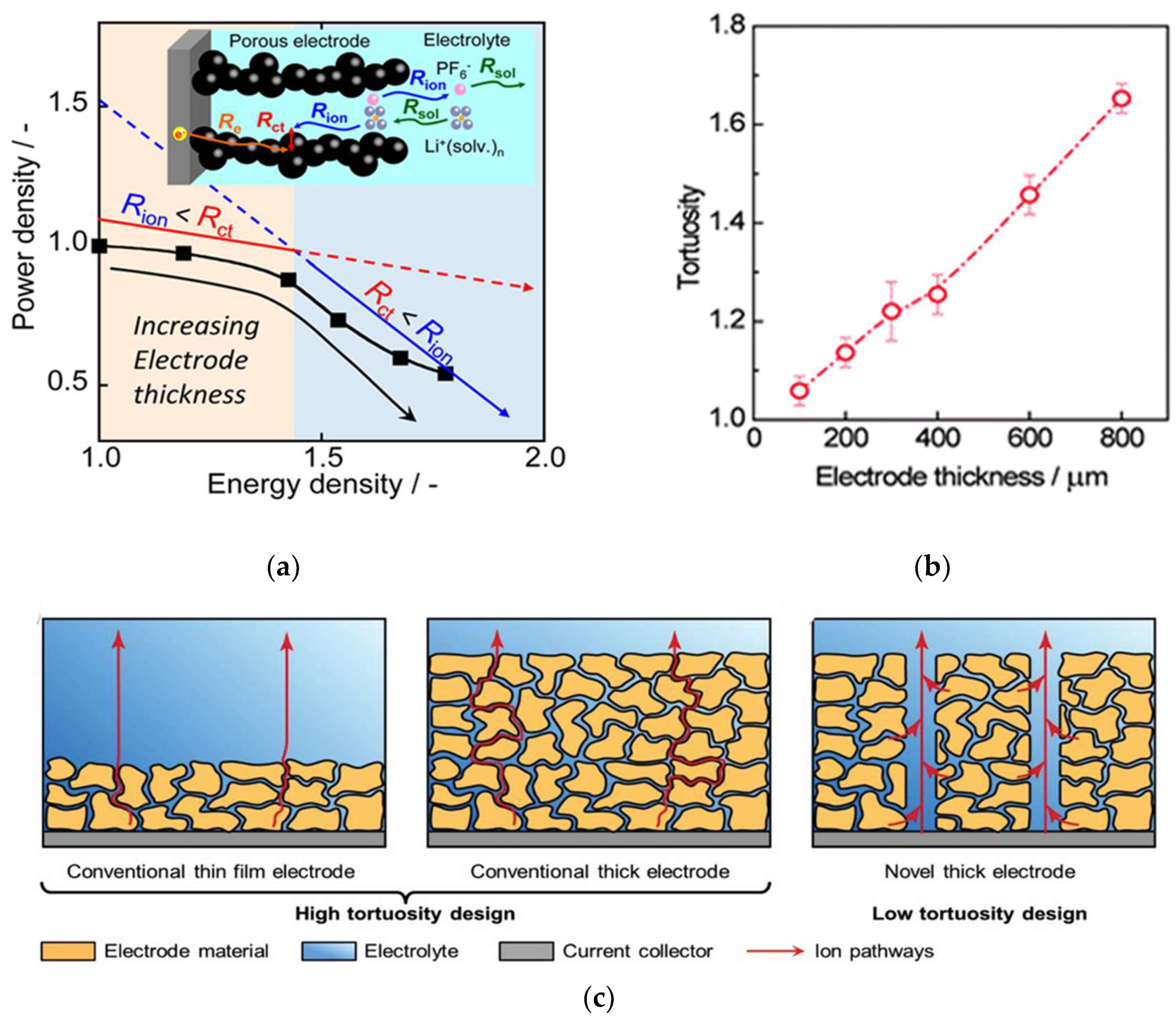
Improving mechanical stability to fabricate crack-free electrodes is just the first step to get the target on energy density of 500 Wh·kg−1. When the porosity of thick electrodes is below 30%, it is found that ionic conduction within such a thick and dense electrode becomes a main reason that causes poor rate performances [2,50,73]. For thick electrodes, the ionic resistance in pores (Rion) is higher than the charge-transfer resistance for Li intercalation (Rct), as shown in Figure 7a, so there are limited ion diffusion behaviors across thick electrodes [74].
According to Equation (2) of the LPD, the LPD is proportional to the porosity of the electrode and inversely proportional to the tortuosity of the electrode. The diffusion coefficient of Li+ is directly related to the diffusion behaviors of Li+ in porous electrodes. Additionally, a simplified expression could be inferred from Equation (2):
D e f f = ε τ D L i
where D e f f is the effective ionic conductivity, ε is the porosity of the electrode, τ is the tortuosity of the electrode and D L i is the intrinsic ions conductivity [75,76,77]. Additionally, the tortuosity reflects the ions diffusion length in the electrodes.
Therefore, there are two strategies to improve ion diffusion behaviors. One is to optimize porosity of the electrode to get better rate performance, and the other is to construct vertical pathways to current collectors for fabricating low-tortuosity electrodes. However, a high porosity would reduce the ratio of active materials in electrodes, and it goes against the design of thick electrodes. Additionally, the tortuosity reflects the ions diffusion length in the electrodes. Additionally, Figure 7b clearly shows that the tortuosity of the electrode increases with the growth of electrode thickness [78]. Therefore, the low-tortuosity design with building ions transport pathways paralleled to the ion transport direction has become a key principle for thick electrodes [29,30,31]. Additionally, the superiority of low-tortuosity design in thick electrodes could be obtained from Figure 7c [13].
It is noteworthy that the low-tortuosity design would increase the porosity of the electrode, but this increase would bring more effective promotion on ions diffusion behavior. Moreover, there is an optimal design of the oriented porosity ε0 and matrix porosity εm, which could balance the ion transport kinetics along the channels and in the matrix. Additionally, it has been given an optimal value (ε0 ≈ 0.11 at ε0 + εm = 0.42) at which the oriented-pore achieved the best rate capability without a sacrifice of the energy density [30].

3.2.1. Optimizing Electrode Porosity

When thick electrodes are discussed, not much attention has been paid to how dense the electrode is, since most of the testing end at coin cell level. However, the practical use of thick electrodes not only needs to consider their mass loading: porosity is equally important [79]. Figure 8a revealed the role of the porosity in the evolution of the rate-limiting step in thick electrodes [48]. The porosity is critical for performing electrochemical properties of electrodes. Additionally, some studies have proven that the electrochemical performance of thick electrodes could be improved through the porosity gradient [80,81].
To put kinetics into perspective, the porosity across the electrode showing a gradient increase is beneficial from the region near to the current collector to the region close to the separator. The reason is that electrodes with large porosity near separators could facilitate fast ion transport while electrodes with small porosity close current collectors could ensure optimum electronic contact [80,82,83,84]. Based on the electrochemical porous-electrode model, two teams obtained the same results via distinct simulation methods. The result is a higher porosity in the electrode near the separator, which can hold more electrolytes and minimize resistance at the electrode [80,82]. Another report also supports this suspect, but it puts forward that it is not much use to construct graded electrode beyond two layers for reducing the resistance across the electrodes. Beyond simulations, the electrodes with staged porosity in order to improve ions migration has been constructed by applying the capillary suspension concept [84]. This strategy is under patent-pending protection application [85].
However, an opposite viewpoint has been given. The highest stresses are located in the electrodes near the current collectors and by increasing the porosity of this region the maximum stress could be reduced. Furthermore, the lower porosity of electrodes near separators would contribute to maintain a higher potential during discharge [81]. Moreover, the comparison of electrochemical performance between directional ice templating with low porosity nearest the separator (DIT LP-S) and directional ice templating with low porosity nearest the current collector (DIT LP-CC) shows that the former performed better rate capability (Figure 8b,c) [86]. Similarly, this strategy also has patent protection [87].

3.2.2. Decreasing Electrode Tortuosity

Figure 8c also gives other sights that both DIT LP-S and DIT LP-CC electrodes performed better rate capability than isotropic ice templating (IIT) electrodes and the IIT electrodes also had poorer rate performance than the traditional slurry casting (SC) electrode. Combining with Figure 8b, these sights indicate that the increased thickness of electrodes would deteriorate the rate performance and decreasing electrode tortuosity could improve electrochemical performance in thick electrodes. Furthermore, more general and sustainable approaches are highly desired to fabricate uniformly aligned microchannels in the electrode.
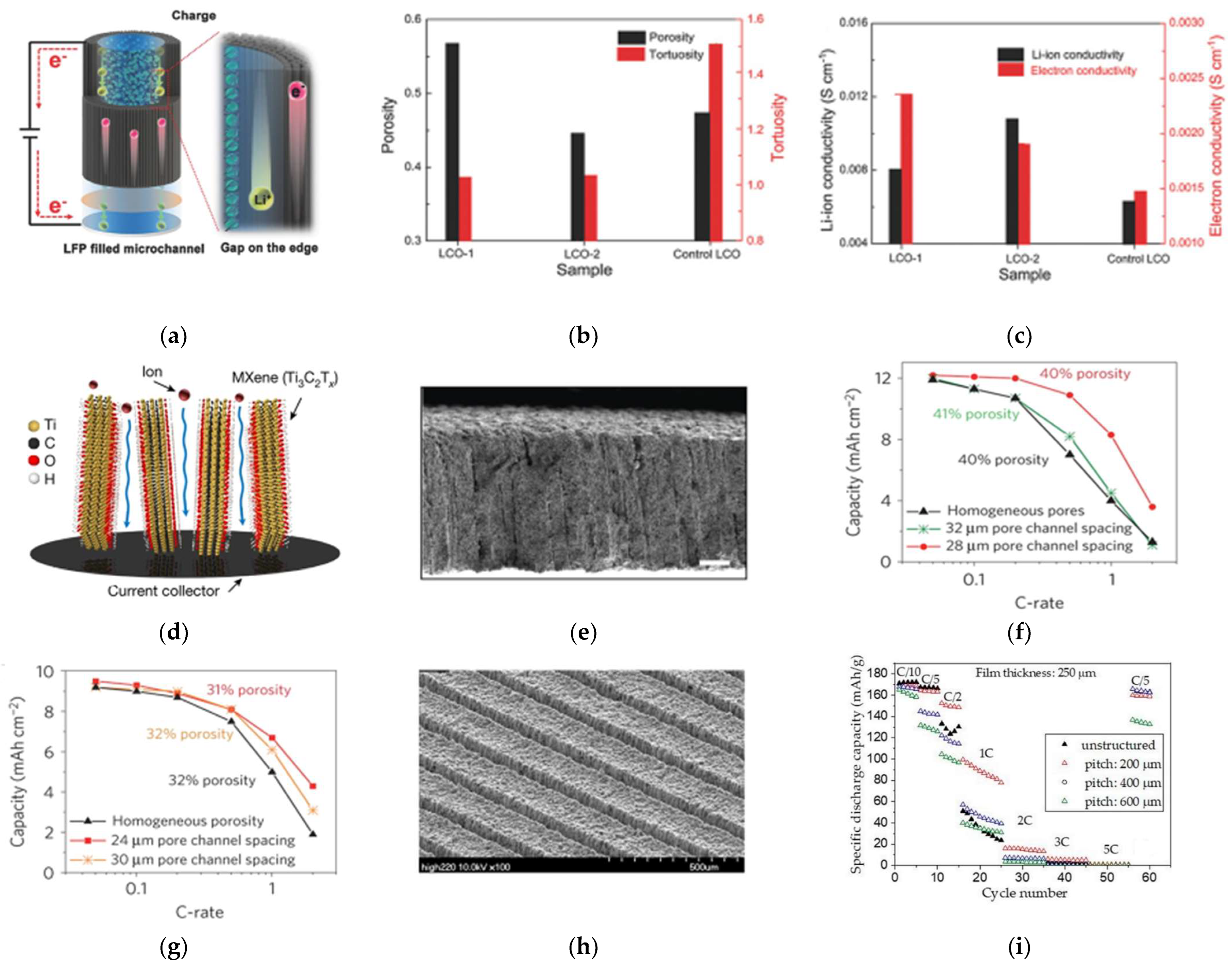
Nature provides many templates and inspirations for improving electrode performance and building hierarchical microstructures [88]. The wood has open channels to transport water, ions and other components along the growth direction. Additionally, the structure provides guidance for making ordered electrodes. Thick electrodes constructed via wood template inherit directional porous structure where it provides pathways for easy ion and electron transport across the entire electrode [25,28,89,90,91]. As shown in Figure 9a, the interconnected carbon framework could provide a conductive network for electron transport while the gap between active materials and frameworks could offer low-tortuosity pathways for ion transport [52]. To further illustrate the value of wood-template, Lu and coworkers constructed the traditional LiCoO2 cathode (control LCO) and the wood-template LiCoO2 cathodes (LCO-1 and LCO-2, the LCO-2 for higher mass loading underwent the double processes of LCO-1) and measured their related properties [92]. The results are given in Figure 9b,c, and the tortuosity of wood-template cathodes is approximately close to 1 due to ordered microchannels and smaller than the control LCO. The ion conductivity and electron conductivity of wood-template cathodes are larger than the control LCO. Through comparing the porosity and ion conductivity between LCO-1 and LCO-2, a larger porosity is not always positive to improve ions diffusion or the LPD.
The ice-template technique is also used to build orientational pores for ion migration [64,86,93]. The ordered pores could be well controlled by adjusting the freezing and sintering parameters. This technique creates electrodes that combine the energy and the power [93]. Moreover, Miller et al. successfully constructed thick electrodes with the thickness-independent electrochemical performance by aligning vertical two-dimensional flakes [72]. Additionally, Figure 9d gives a scheme of thick electrodes constructed by this guidance, and approximately 200 μ m is the maximum thickness of each film due to the ion transport limitations [32]. It is another proof of the LPD.
Commercial availability is also a critical factor for building directional aligned pores in electrodes. Additionally, a simple, up-scalable and inexpensive technique to construct pathways parallel to the direction of the Li+ migration has been proposed by applying a magnetic field during the electrode fabrication (Figure 9e) [94,95,96,97,98,99]. A magnetic control method based on sacrificial features was reported, magnetized nylon rods or magnetic emulsions were used as a template to fabricate directionally aligned pore arrays in the thick electrode [95]. Additionally, it is noteworthy that the aligned pore structure performs higher areal capacity under the same conditions (at constant thickness and total porosity) and smaller pore spacings are superior, as shown in Figure 9f,g.
Moreover, Figure 9f,g give a critical viewpoint that the pore parameters (like diameter and spacing) play a pivotal key on rate performance of electrodes. Therefore, a more precise technique for constructing vertically aligned pores is requested and essential. The laser-based manufacturing process attracts more attention in the low-tortuosity design for thick electrodes. This concept involves high-precision ablation of a small fraction of the active material from the initial coating and generating additional diffusion pathways (Figure 9h) [10,100]. The laser processing on electrodes is inevitably accompanied by slight capacity loss but significant improvements in rate performance [101,102,103]. By using 200 ns-laser radiation and a pitch distance of 200 μ m , the loss in active material can reach values of about 30 wt.%, while a pitch distance of 600 μ m would reduce the material loss below 10 wt.% [104]. Additionally, the rate performance in different pitch distances were given in Figure 9i [105].
Furthermore, the ultrashort pulse duration in the femtosecond (fs) or picosecond (ps) range is less than the heat diffusion time. Additionally, the ablation volume is emitted before any heat diffusion or thermal damage occurs and side effects are significantly reduced [106]. Additionally, due to the cold nature of fs-laser ablation, a high-aspect ratio of approximately 15 could be reached, which related to the capacity loss. Therefore, it can construct fine and accurate alignment hole array. Additionally, the ideal pore parameters for maximizing the rate capability could be identified by evaluating the ions distribution in electrodes [107]. Furthermore, the surface on laser-generated structures leads to an accelerated and homogenous wetting of the electrodes with liquid electrolyte [103,104].

3.3. Summary

This chapter gives the recent efforts on improving the CCT and the LPD to construct thicker electrodes. It must be emphasized again that the first law of thick electrodes is to obtain high performance electrodes with high mass loading and high accessible areal capacity, not thicker electrodes. Some thick electrodes constructed by the above methods show lower volumetric specific capacity that have no competition with the traditional electrodes. Additionally, some design of thick electrodes cannot be transferred directly to state-of-the-art large-scale cell manufacturing processes in industry. Table 1 gives the summary of the thick electrodes. Additionally, the volumetric specific capacity of thick electrodes is not below 400 mAh·cm−3 which is the current level of traditional electrodes.

4. Conclusions and Outlook

Recently moving towards carbon neutrality has become a global consensus and green transportation attracts more attention. The EVs with the driving range of above 500 km could become more competitive to survive in the market for automobiles. Additionally, a practicable way to reach this value is to adopt thick electrodes with high mass loading and high area capacity. The obstacles that stand in the way of using thick electrodes are weak mechanical stability and poor electrochemical performance, or are limited by the CCT and the LPD. Here, the understanding of these mechanisms and the recent efforts on breaking the limitations are given.
The design of thick electrodes is aimed at obtaining higher energy density of LIBs at battery-pack level, but not larger thickness for electrodes. Some thick electrodes with large porosity show lower volumetric specific capacity that go against the original intention of this design. Therefore, two corresponding parameters to evaluate the thick electrode is needed, such as thickness and porosity, areal capacity and volumetric capacity.
The design of thick electrodes is aimed at applications for practical use like EVs, and the preparation process must be suitable for a large-scale use. Some methods for fabricating thick electrodes are only for a laboratory scale. Some technologies with drying process may cause the microstructural heterogeneity in the electrodes due to the drying-induced migration of the binder to the electrode surface. Additionally, combining with the requirement of low-cost solution, some solvent-free manufacturing technologies are appropriate, like the dry-coated technique, which is suitable for mass manufacture and cuts the cost of using and removing the toxic solvents. Additionally, an environmentally friendly industry is more easily accepted by local government and residents.
The electrochemical performance is the most basic requirements for thick electrodes. Decreasing the tortuosity of thick electrodes by fabricating ordered microchannels paralleling the diffusion of Li+ has been considered as the most effective ways to help thick electrodes in performing better properties. Because the low-tortuosity design resulted in active mass loss, it is essential to precisely construct vertical channels. From the studies on constructing aligned pathways, the laser-ablation process could be better controlled to precisely adjust parameters of the vertical channels.

Author Contributions

Conceptualization, J.Z., L.J. and J.P.Z.; validation, Y.L.; investigation, G.X.; resources, L.J.; data curation, G.X.; writing—original draft preparation, G.X.; writing—review and editing, Y.L. and N.Q.; visualization, N.Q.; supervision, J.Z. and J.P.Z.; project administration, L.J. and S.G.; funding acquisition, J.Z. and S.G. All authors have read and agreed to the published version of the manuscript.

Funding

The work is supported by China Shenhua Coal to Liquid and Chemical Shanghai Research Institute, Grant No. SAC-B-CT-TECH-2022-04-25, and National Science Foundation of China, Grant No. 51777140, and the Fundamental Research Funds for the Central Universities at Tongji University, Grant No. 17002150019.

Institutional Review Board Statement

Not applicable.

Informed Consent Statement

Not applicable.

Data Availability Statement

No new data were created in this paper.

Conflicts of Interest

The funders had no role in the design of the study; in the collection, analyses, or interpretation of data; in the writing of the manuscript; or in the decision to publish the results.

References

  1. Rempel, J. Vehicle Technologies Office Merit Review 2015: High Energy High Power Battery Exceeding PHEV-40 Requirements. Available online: https://www.energy.gov/sites/prod/files/2015/06/f23/es209_rempel_2015_p.pdf (accessed on 30 January 2023).
  2. Gallagher, K.G.; Trask, S.E.; Bauer, C.; Woehrle, T.; Lux, S.F.; Tschech, M.; Lamp, P.; Polzin, B.J.; Ha, S.; Long, B.; et al. Optimizing Areal Capacities through Understanding the Limitations of Lithium-Ion Electrodes. J. Electrochem. Soc. 2015, 163, A138–A149. [Google Scholar] [CrossRef]
  3. Gröger, O.; Gasteiger, H.A.; Suchsland, J.-P. Review—Electromobility: Batteries or Fuel Cells? J. Electrochem. Soc. 2015, 162, A2605–A2622. [Google Scholar] [CrossRef]
  4. Andre, D.; Kim, S.-J.; Lamp, P.; Lux, S.F.; Maglia, F.; Paschos, O.; Stiaszny, B. Future generations of cathode materials: An automotive industry perspective. J. Mater. Chem. A 2015, 3, 6709–6732. [Google Scholar] [CrossRef]
  5. China Society of Automotive Engineers. Technology Roadmap of Clean and New Energy Vehicles 2.0. Available online: http://zhishi.sae-china.org/ppt.html?id=2100 (accessed on 30 January 2023).
  6. Xia, C.; Kwok, C.; Nazar, L. A high-energy-density lithium-oxygen battery based on a reversible four-electron conversion to lithium oxid. Science 2018, 361, 777–781. [Google Scholar] [CrossRef] [Green Version]
  7. Zhang, J.; Wang, P.F.; Bai, P.; Wan, H.; Liu, S.; Hou, S.; Pu, X.; Xia, J.; Zhang, W.; Wang, Z.; et al. Interfacial Design for a 4.6 V High-Voltage Single-Crystalline LiCoO2 Cathode. Adv. Mater. 2022, 34, e2108353. [Google Scholar] [CrossRef]
  8. Du, K.; Tao, R.; Guo, C.; Li, H.; Liu, X.; Guo, P.; Wang, D.; Liang, J.; Li, J.; Dai, S.; et al. In-situ synthesis of porous metal fluoride@carbon composite via simultaneous etching/fluorination enabled superior Li storage performance. Nano Energy 2022, 103, 107862. [Google Scholar] [CrossRef]
  9. Shi, B.; Shang, Y.; Pei, Y.; Pei, S.; Wang, L.; Heider, D.; Zhao, Y.Y.; Zheng, C.; Yang, B.; Yarlagadda, S.; et al. Low Tortuous, Highly Conductive, and High-Areal-Capacity Battery Electrodes Enabled by Through-thickness Aligned Carbon Fiber Framework. Nano Lett. 2020, 20, 5504–5512. [Google Scholar] [CrossRef] [PubMed]
  10. Pfleging, W. A review of laser electrode processing for development and manufacturing of lithium-ion batteries. Nanophotonics 2018, 7, 549–573. [Google Scholar] [CrossRef]
  11. Liu, J.; Bao, Z.; Cui, Y.; Dufek, E.J.; Goodenough, J.B.; Khalifah, P.; Li, Q.; Liaw, B.Y.; Liu, P.; Manthiram, A.; et al. Pathways for practical high-energy long-cycling lithium metal batteries. Nat. Energy 2019, 4, 180–186. [Google Scholar] [CrossRef] [Green Version]
  12. Cheng, H.; Li, K. Charge delivery goes the distance. Science 2017, 356, 582–583. [Google Scholar] [CrossRef] [PubMed]
  13. Kuang, Y.; Chen, C.; Kirsch, D.; Hu, L. Thick Electrode Batteries: Principles, Opportunities, and Challenges. Adv. Energy Mater. 2019, 9, 1901457. [Google Scholar] [CrossRef]
  14. Zheng, H.; Li, J.; Song, X.; Liu, G.; Battaglia, V. A comprehensive understanding of electrode thickness effects on the electrochemical performances of Li-ion battery cathodes. Electrochim. Acta 2012, 71, 258–265. [Google Scholar] [CrossRef]
  15. Wang, J.S.; Liu, P.; Sherman, E.; Verbrugge, M.; Tataria, H. Formulation and characterization of ultra-thick electrodes for high energy lithium-ion batteries employing tailored metal foams. J. Power Sources 2011, 196, 8714–8718. [Google Scholar] [CrossRef]
  16. Singh, K.; Tirumkudulu, M. Cracking in drying colloidal films. Phys. Rev. Lett. 2007, 98, 218302. [Google Scholar] [CrossRef] [PubMed] [Green Version]
  17. Chiu, R.; Garino, T.; Cima, M. Drying of Granular Ceramic Films: I, Effect of Processing Variables on Cracking Behavior. J. Am. Ceram. Soc. 1993, 76, 2257–2264. [Google Scholar] [CrossRef]
  18. Slowik, V.; Ju, J. Discrete modeling of plastic cement paste subjected to drying. Cem. Concr. Compos. 2011, 33, 925–935. [Google Scholar] [CrossRef]
  19. Tirumkudulu, M.; Russel, W. Cracking in drying latex films. Langmuir 2005, 21, 4938–4948. [Google Scholar] [CrossRef] [PubMed]
  20. Tambio, S.; Cadiou, F.; Maire, E.; Besnard, N.; Deschamps, M.; Lestriez, B. The Concept of Effective Porosity in the Discharge Rate Performance of High-Density Positive Electrodes for Automotive Application. J. Electrochem. Soc. 2020, 167, 160509. [Google Scholar] [CrossRef]
  21. Lu, C.; Huang, Q.; Chen, X. High-performance silicon nanocomposite based ionic actuators. J. Mater. Chem. A 2020, 8, 9228–9238. [Google Scholar] [CrossRef]
  22. Yan, L.; Yudong, L.; Ting’an, Z.; Naixiang, F. Research on the Penetration Depth in Aluminum Reduction Cell with New Type of Anode and Cathode Structures. JOM 2014, 66, 1202–1209. [Google Scholar] [CrossRef]
  23. Fang, R.; Zhao, S.; Hou, P.; Cheng, M.; Wang, S.; Cheng, H.; Liu, C.; Li, F. 3D Interconnected Electrode Materials with Ultrahigh Areal Sulfur Loading for Li-S Batteries. Adv. Mater. 2016, 28, 3374–3382. [Google Scholar] [CrossRef] [PubMed]
  24. Li, G.; Ouyang, T.; Xiong, T.; Jiang, Z.; Adekoya, D.; Wu, Y.; Huang, Y.; Balogun, M. All-carbon-frameworks enabled thick electrode with exceptional high-areal-capacity for Li-Ion storage. Carbon 2021, 174, 1–9. [Google Scholar] [CrossRef]
  25. Woodward, R.; Markoulidis, F.; Luca, F.D.; Anthony, D.; Malko, D.; McDonald, T.; Shaffer, M.; Bismarck, A. Carbon foams from emulsion-templated reduced graphene oxide polymer composites: Electrodes for supercapacitor devices. J. Mater. Chem. A 2018, 6, 1840–1849. [Google Scholar] [CrossRef] [Green Version]
  26. Sun, H.; Mei, L.; Liang, J.; Zhao, Z.; Lee, C.; Fei, H.; Ding, M.; Lau, J.; Li, M.; Wang, C.; et al. Three-dimensional holey-graphene/niobia composite architectures for ultrahigh-rate energy storage. Science 2017, 356, 599–604. [Google Scholar] [CrossRef] [Green Version]
  27. Kang, J.; Pham, H.Q.; Kang, D.-H.; Park, H.-Y.; Song, S.-W. Improved rate capability of highly loaded carbon fiber-interwoven LiNi 0.6 Co 0.2 Mn 0.2 O 2 cathode material for high-power Li-ion batteries. J. Alloys Compd. 2016, 657, 464–471. [Google Scholar] [CrossRef]
  28. Shen, F.; Luo, W.; Dai, J.; Yao, Y.; Zhu, M.; Hitz, E.; Tang, Y.; Chen, Y.; Sprenkle, V.L.; Li, X.; et al. Ultra-Thick, Low-Tortuosity, and Mesoporous Wood Carbon Anode for High-Performance Sodium-Ion Batteries. Adv. Energy Mater. 2016, 6, 1600377. [Google Scholar] [CrossRef]
  29. Ebner, M.; Chung, D.-W.; García, R.E.; Wood, V. Tortuosity Anisotropy in Lithium-Ion Battery Electrodes. Adv. Energy Mater. 2014, 4, 1301278. [Google Scholar] [CrossRef]
  30. Xiong, R.; Zhang, Y.; Wang, Y.; Song, L.; Li, M.; Yang, H.; Huang, Z.; Li, D.; Zhou, H. Scalable Manufacture of High-Performance Battery Electrodes Enabled by a Template-Free Method. Small Methods 2021, 5, 2100280. [Google Scholar] [CrossRef]
  31. Zhang, L.; Pan, Y.; Chen, Y.; Li, M.; Liu, P.; Wang, C.; Wang, P.; Lu, H. Designing vertical channels with expanded interlayers for Li-ion batteries. Chem. Commun. 2019, 55, 4258–4261. [Google Scholar] [CrossRef] [PubMed]
  32. Xia, Y.; Mathis, T.S.; Zhao, M.Q.; Anasori, B.; Dang, A.; Zhou, Z.; Cho, H.; Gogotsi, Y.; Yang, S. Thickness-independent capacitance of vertically aligned liquid-crystalline MXenes. Nature 2018, 557, 409–412. [Google Scholar] [CrossRef]
  33. Singh, M.; Kaiser, J.; Hahn, H. Thick Electrodes for High Energy Lithium Ion Batteries. J. Electrochem. Soc. 2015, 162, A1196–A1201. [Google Scholar] [CrossRef]
  34. Kato, Y.; Shiotani, S.; Morita, K.; Suzuki, K.; Hirayama, M.; Kanno, R. All-Solid-State Batteries with Thick Electrode Configurations. J. PhysIcal Chem. Lett. 2018, 9, 607–613. [Google Scholar] [CrossRef] [PubMed]
  35. Kubanska, A.; Castro, L.; Tortet, L.; Dollé, M.; Bouchet, R. Effect of composite electrode thickness on the electrochemical performances of all-solid-state li-ion batteries. J. Electroceram. 2017, 38, 189–196. [Google Scholar] [CrossRef]
  36. Hong, S.-B.; Lee, Y.-J.; Kim, U.-H.; Bak, C.; Lee, Y.M.; Cho, W.; Hah, H.J.; Sun, Y.-K.; Kim, D.-W. All-Solid-State Lithium Batteries: Li+-Conducting Ionomer Binder for Dry-Processed Composite Cathodes. ACS Energy Lett. 2022, 7, 1092–1100. [Google Scholar] [CrossRef]
  37. Kukay, A.; Sahore, R.; Parejiya, A.; Hawley, W.; Li, J.; Wood, D. Aqueous Ni-rich-cathode dispersions processed with phosphoric acid for lithium-ion batteries with ultra-thick electrodes. J. Colloid Interface Sci. 2021, 581, 635–643. [Google Scholar] [CrossRef]
  38. Li, H. Practical Evaluation of Li-Ion Batteries. Joule 2019, 3, 911–914. [Google Scholar] [CrossRef] [Green Version]
  39. Shin, H.; Santamarina, J. Desiccation cracks in saturated fine-grained soils: Particle-level phenomena and effective-stress analysis. Géotechnique 2011, 61, 961–972. [Google Scholar] [CrossRef]
  40. Lura, P.; Pease, B.; Mazzotta, G.B.; Rajabipour, F.; Weiss, J. Influence of Shrinkage-Reducing Admixtures on Development of Plastic Shrinkage Cracks. ACI Mater. J. 2007, 104, 187–194. [Google Scholar] [CrossRef]
  41. Du, Z.; Rollag, K.M.; Li, J.; An, S.J.; Wood, M.; Sheng, Y.; Mukherjee, P.P.; Daniel, C.; Wood, D.L. Enabling aqueous processing for crack-free thick electrodes. J. Power Sources 2017, 354, 200–206. [Google Scholar] [CrossRef] [Green Version]
  42. Dufresne, E.R.; Corwin, E.I.; Greenblatt, N.A.; Ashmore, J.; Wang, D.Y.; Dinsmore, A.D.; Cheng, J.X.; Xie, X.S.; Hutchinson, J.W.; Weitz, D.A. Flow and fracture in drying nanoparticle suspensions. Phys. Rev. Lett. 2003, 91, 224501. [Google Scholar] [CrossRef] [Green Version]
  43. Birk-Braun, N.; Yunus, K.; Rees, E.J.; Schabel, W.; Routh, A.F. Generation of strength in a drying film: How fracture toughness depends on dispersion properties. Phys. Rev. Lett. 2017, 95, 022610. [Google Scholar] [CrossRef] [PubMed] [Green Version]
  44. Ibing, L.; Gallasch, T.; Schneider, P.; Niehoff, P.; Hintennach, A.; Winter, M.; Schappacher, F.M. Towards water based ultra-thick Li ion battery electrodes—A binder approach. J. Power Sources 2019, 423, 183–191. [Google Scholar] [CrossRef]
  45. Kumberg, J.; Müller, M.; Diehm, R.; Spiegel, S.; Wachsmann, C.; Bauer, W.; Scharfer, P.; Schabel, W. Drying of Lithium-Ion Battery Anodes for Use in High-Energy Cells: Influence of Electrode Thickness on Drying Time, Adhesion, and Crack Formation. Energy Technol. 2019, 7, 1900722. [Google Scholar] [CrossRef]
  46. Park, S.-H.; King, P.J.; Tian, R.; Boland, C.S.; Coelho, J.; Zhang, C.; McBean, P.; McEvoy, N.; Kremer, M.P.; Daly, D.; et al. High areal capacity battery electrodes enabled by segregated nanotube networks. Nat. Energy 2019, 4, 560–567. [Google Scholar] [CrossRef]
  47. Gao, H.; Wu, Q.; Hu, Y.; Zheng, J.P.; Amine, K.; Chen, Z. Revealing the Rate-Limiting Li-Ion Diffusion Pathway in Ultrathick Electrodes for Li-Ion Batteries. J. Phys. Chem. Lett. 2018, 9, 5100–5104. [Google Scholar] [CrossRef] [PubMed]
  48. Hu, J.; Wu, B.; Cao, X.; Bi, Y.; Chae, S.; Niu, C.; Xiao, B.; Tao, J.; Zhang, J.; Xiao, J. Evolution of the rate-limiting step: From thin film to thick Ni-rich cathodes. J. Power Sources 2020, 454, 227966. [Google Scholar] [CrossRef]
  49. Appiah, W.; Park, J.; Song, S.; Byun, S.; Ryou, M.; Lee, Y. Design optimization of LiNi0.6Co0.2Mn0.2O2/graphite lithium-ion cells based on simulation and experimental data. J. Power Sources 2016, 319, 147–158. [Google Scholar] [CrossRef]
  50. Li, Z.; Yin, L.; Mattei, G.S.; Cosby, M.R.; Lee, B.-S.; Wu, Z.; Bak, S.-M.; Chapman, K.W.; Yang, X.-Q.; Liu, P.; et al. Synchrotron Operando Depth Profiling Studies of State-of-Charge Gradients in Thick Li(Ni0.8Mn0.1Co0.1)O2 Cathode Films. Chem. Mater. 2020, 32, 6358–6364. [Google Scholar] [CrossRef]
  51. Xu, C.; Li, Q.; Wang, Q.; Kou, X.; Fang, H.-T.; Yang, L. Femtosecond laser drilled micro-hole arrays in thick and dense 2D nanomaterial electrodes toward high volumetric capacity and rate performance. J. Power Sources 2021, 492, 229638. [Google Scholar] [CrossRef]
  52. Chen, C.; Zhang, Y.; Li, Y.; Kuang, Y.; Song, J.; Luo, W.; Wang, Y.; Yao, Y.; Pastel, G.; Xie, J.; et al. Highly Conductive, Lightweight, Low-Tortuosity Carbon Frameworks as Ultrathick 3D Current Collectors. Adv. Energy Mater. 2017, 7, 1700595. [Google Scholar] [CrossRef]
  53. Sahore, R.; Wood, D.L.; Kukay, A.; Grady, K.M.; Li, J.; Belharouak, I. Towards Understanding of Cracking during Drying of Thick Aqueous-Processed LiNi0.8Mn0.1Co0.1O2 Cathodes. ACS Sustain. Chem. Eng. 2020, 8, 3162–3169. [Google Scholar] [CrossRef]
  54. Yang, G.F.; Song, K.Y.; Joo, S.K. A metal foam as a current collector for high power and high capacity lithium iron phosphate batteries. J. Mater. Chem. A 2014, 2, 19648–19652. [Google Scholar] [CrossRef] [Green Version]
  55. Yang, Z.; Tian, J.; Ye, Z.; Jin, Y.; Cui, C.; Xie, Q.; Wang, J.; Zhang, G.; Dong, Z.; Miao, Y.; et al. High energy and high power density supercapacitor with 3D Al foam-based thick graphene electrode: Fabrication and simulation. Energy Storage Mater. 2020, 33, 18–25. [Google Scholar] [CrossRef]
  56. Yang, G.-F.; Song, K.-Y.; Joo, S.-K. Ultra-thick Li-ion battery electrodes using different cell size of metal foam current collectors. RSC Adv. 2015, 5, 16702–16706. [Google Scholar] [CrossRef] [Green Version]
  57. Hu, L.; La Mantia, F.; Wu, H.; Xie, X.; McDonough, J.; Pasta, M.; Cui, Y. Lithium-Ion Textile Batteries with Large Areal Mass Loading. Adv. Energy Mater. 2011, 1, 1012–1017. [Google Scholar] [CrossRef]
  58. Al-Shroofy, M.; Zhang, Q.; Xu, J.; Chen, T.; Kaur, A.P.; Cheng, Y.-T. Solvent-free dry powder coating process for low-cost manufacturing of LiNi1/3Mn1/3Co1/3O2 cathodes in lithium-ion batteries. J. Power Sources 2017, 352, 187–193. [Google Scholar] [CrossRef] [Green Version]
  59. Park, D.-W.; Cañas, N.A.; Wagner, N.; Friedrich, K.A. Novel solvent-free direct coating process for battery electrodes and their electrochemical performance. J. Power Sources 2016, 306, 758–763. [Google Scholar] [CrossRef] [Green Version]
  60. Qin, X.; Wang, X.; Xie, J.; Wen, L. Hierarchically porous and conductive LiFePO4 bulk electrode: Binder-free and ultrahigh volumetric capacity Li-ion cathode. J. Mater. Chem. 2011, 21, 12444–12448. [Google Scholar] [CrossRef]
  61. Elango, R.; Demortière, A.; Andrade, V.; Morcrette, M.; Seznec, V. Thick Binder-Free Electrodes for Li–Ion Battery Fabricated Using Templating Approach and Spark Plasma Sintering Reveals High Areal Capacity. Adv. Energy Mater. 2018, 8, 1703031. [Google Scholar] [CrossRef]
  62. Sun, C.; Liu, S.; Shi, X.; Lai, C.; Liang, J.; Chen, Y. 3D printing nanocomposite gel-based thick electrode enabling both high areal capacity and rate performance for lithium-ion battery. Chem. Eng. J. 2020, 381, 122641. [Google Scholar] [CrossRef]
  63. Tang, X.; Zhou, H.; Cai, Z.; Cheng, D.; He, P.; Xie, P.; Zhang, D.; Fan, T. Generalized 3D Printing of Graphene-Based Mixed-Dimensional Hybrid Aerogels. ACS Nano 2018, 12, 3502–3511. [Google Scholar] [CrossRef]
  64. Gao, X.; Yang, X.; Sun, Q.; Luo, J.; Liang, J.; Li, W.; Wang, J.; Wang, S.; Li, M.; Li, R.; et al. Converting a thick electrode into vertically aligned “Thin electrodes” by 3D-Printing for designing thickness independent Li-S cathode. Energy Storage Mater. 2020, 24, 682–688. [Google Scholar] [CrossRef]
  65. Sajadi, S.M.; Enayat, S.; Vásárhelyi, L.; Alabastri, A.; Lou, M.; Sassi, L.M.; Kutana, A.; Bhowmick, S.; Durante, C.; Kukovecz, Á.; et al. Three-dimensional printing of complex graphite structures. Carbon 2021, 181, 260–269. [Google Scholar] [CrossRef]
  66. Sotomayor, M.; Torre-Gamarra, C.; Bucheli, W.; Amarilla, J.; Varez, A.; LevenfelD, B.; Sanchez, J. Additive-free Li4Ti5O12 thick electrodes for Li-ion batteries with high electrochemical performance. J. Mater. Chem. A 2018, 6, 5952–5961. [Google Scholar] [CrossRef]
  67. de la Torre-Gamarra, C.; Sotomayor, M.E.; Sanchez, J.-Y.; Levenfeld, B.; Várez, A.; Laïk, B.; Pereira-Ramos, J.-P. High mass loading additive-free LiFePO4 cathodes with 500 μm thickness for high areal capacity Li-ion batteries. J. Power Sources 2020, 458, 228033. [Google Scholar] [CrossRef]
  68. Sotomayor, M.E.; Torre-Gamarra, C.d.l.; Levenfeld, B.; Sanchez, J.-Y.; Varez, A.; Kim, G.-T.; Varzi, A.; Passerini, S. Ultra-thick battery electrodes for high gravimetric and volumetric energy density Li-ion batteries. J. Power Sources 2019, 437, 226923. [Google Scholar] [CrossRef]
  69. Duong, H.; Shin, J.; Yudi, Y. Dry Electrode Coating Technology; Maxwell Technologies, Inc.: San Diego, CA, USA, 2018. [Google Scholar]
  70. Ludwig, B.; Zheng, Z.; Shou, W.; Wang, Y.; Pan, H. Solvent-Free Manufacturing of Electrodes for Lithium-ion Batteries. Sci. Rep. 2016, 6, 23150. [Google Scholar] [CrossRef] [Green Version]
  71. Fu, K.; Yao, Y.; Dai, J.; Hu, L. Progress in 3D Printing of Carbon Materials for Energy-Related Applications. Adv. Mater. 2017, 29, 1603486. [Google Scholar] [CrossRef]
  72. Yoon, Y.; Lee, K.; Kwon, S.; Seo, S.; Yoo, H.; Kim, S.; Shin, Y.; Park, Y.; Kim, D.; Choi, J.Y.; et al. Vertical alignments of graphene sheets spatially and densely piled for fast ion diffusion in compact supercapacitors. ACS Nano 2014, 8, 4580–4590. [Google Scholar] [CrossRef]
  73. Johns, P.A.; Roberts, M.R.; Wakizaka, Y.; Sanders, J.H.; Owen, J.R. How the electrolyte limits fast discharge in nanostructured batteries and supercapacitors. Electrochem. Commun. 2009, 11, 2089–2092. [Google Scholar] [CrossRef] [Green Version]
  74. Ogihara, N.; Itou, Y.; Sasaki, T.; Takeuchi, Y. Impedance Spectroscopy Characterization of Porous Electrodes under Different Electrode Thickness Using a Symmetric Cell for High-Performance Lithium-Ion Batteries. J. Phys. Chem. C 2015, 119, 4612–4619. [Google Scholar] [CrossRef]
  75. Vijayaraghavan, B.; Ely, D.R.; Chiang, Y.-M.; García-García, R.; Garcia, R.E. An Analytical Method to Determine Tortuosity in Rechargeable Battery Electrodes. J. Electrochem. Soc. 2012, 159, A548–A552. [Google Scholar] [CrossRef]
  76. Harris, S.; Lu, P. Effects of Inhomogeneities—Nanoscale to Mesoscale—On the Durability of Li-Ion Batteries. J. Phys. Chem. C 2013, 117, 6481–6492. [Google Scholar] [CrossRef]
  77. Ebner, M.; Wood, V. Tool for Tortuosity Estimation in Lithium Ion Battery Porous Electrodes. J. Electrochem. Soc. 2015, 162, A3064–A3070. [Google Scholar] [CrossRef] [Green Version]
  78. Li, H.; Tao, Y.; Zheng, X.; Luo, J.; Kang, F.; Cheng, H.-M.; Yang, Q.-H. Ultra-thick graphene bulk supercapacitor electrodes for compact energy storage. Energy Environ. Sci. 2016, 9, 3135–3142. [Google Scholar] [CrossRef]
  79. Xiao, Q.; Gu, M.; Yang, H.; Li, B.; Zhang, C.; Liu, Y.; Liu, F.; Dai, F.; Yang, L.; Liu, Z.; et al. Inward lithium-ion breathing of hierarchically porous silicon anodes. Nat. Commun. 2015, 6, 8844. [Google Scholar] [CrossRef] [Green Version]
  80. Ramadesigan, V.; Methekar, R.N.; Latinwo, F.; Braatz, R.D.; Subramanian, V.R. Optimal Porosity Distribution for Minimized Ohmic Drop across a Porous Electrode. J. Electrochem. Soc. 2010, 157, A1328–A1334. [Google Scholar] [CrossRef]
  81. Golmon, S.; Maute, K.; Dunn, M.L. Multiscale design optimization of lithium ion batteries using adjoint sensitivity analysis. Int. J. Numer. Methods Eng. 2012, 92, 475–494. [Google Scholar] [CrossRef]
  82. Golmon, S.; Maute, K.; Dunn, M. A design optimization methodology for Li+ batteries. J. Power Sources 2014, 253, 239–250. [Google Scholar] [CrossRef]
  83. Qi, Y.; Jang, T.; Ramadesigan, V.; Schwartz, D.T.; Subramanian, V.R. Is There a Benefit in Employing Graded Electrodes for Lithium-Ion Batteries? J. Electrochem. Soc. 2017, 164, A3196–A3207. [Google Scholar] [CrossRef] [Green Version]
  84. Bitsch, B.; Gallasch, T.; Schroeder, M.; Börner, M.; Winter, M.; Willenbacher, N. Capillary suspensions as beneficial formulation concept for high energy density Li-ion battery electrodes. J. Power Sources 2016, 328, 114–123. [Google Scholar] [CrossRef]
  85. Wang, C.P.; Lopatin, S.D.; Bachrach, R.Z.; Sikha, G. Graded Electrode Technologies for High Energy Lithium-Ion Batteries. U.S. Patent 20110168550, 21 July 2011. [Google Scholar]
  86. Huang, C.; Dontigny, M.; Zaghib, K.; Grant, P.S. Low-tortuosity and graded lithium ion battery cathodes by ice templating. J. Mater. Chem. A 2019, 7, 21421–21431. [Google Scholar] [CrossRef] [Green Version]
  87. Kolosnitsyn, V.; Karaseva, E. Improvements relating to electrode structures in batteries. European Patent 2006010894, 02 February 2006. [Google Scholar]
  88. Huebsch, N.; Mooney, D.J. Inspiration and application in the evolution of biomaterials. Nature 2009, 462, 426–432. [Google Scholar] [CrossRef] [Green Version]
  89. Ma, Y.; Yao, D.; Liang, H.; Yin, J.; Xia, Y.; Zuo, K.; Zeng, Y.-P. Ultra-thick wood biochar monoliths with hierarchically porous structure from cotton rose for electrochemical capacitor electrodes. Electrochim. Acta 2020, 352, 136452. [Google Scholar] [CrossRef]
  90. Liu, K.; Mo, R.; Dong, W.; Zhao, W.; Huang, F. Nature-derived, structure and function integrated ultra-thick carbon electrode for high-performance supercapacitors. J. Mater. Chem. A 2020, 8, 20072–20081. [Google Scholar] [CrossRef]
  91. Lv, Z.; Yue, M.; Ling, M.; Zhang, H.; Yan, J.; Zheng, Q.; Li, X. Controllable Design Coupled with Finite Element Analysis of Low-Tortuosity Electrode Architecture for Advanced Sodium-Ion Batteries with Ultra-High Mass Loading. Adv. Energy Mater. 2021, 11, 2003725. [Google Scholar] [CrossRef]
  92. Lu, L.L.; Lu, Y.Y.; Xiao, Z.J.; Zhang, T.W.; Zhou, F.; Ma, T.; Ni, Y.; Yao, H.B.; Yu, S.H.; Cui, Y. Wood-Inspired High-Performance Ultrathick Bulk Battery Electrodes. Adv. Mater. 2018, 30, e1706745. [Google Scholar] [CrossRef]
  93. Behr, S.; Amin, R.; Chiang, Y.M.; Tomsia, A.P. Highly structured, additive free lithium-ion cathodes by freeze-casting technology. Ceram. Forum Int. 2015, 92, E39–E43. [Google Scholar]
  94. Li, L.; Erb, R.M.; Wang, J.; Wang, J.; Chiang, Y.M. Fabrication of Low-Tortuosity Ultrahigh-Area-Capacity Battery Electrodes through Magnetic Alignment of Emulsion-Based Slurries. Adv. Energy Mater. 2018, 9, 1802472. [Google Scholar] [CrossRef]
  95. Sander, J.S.; Erb, R.M.; Li, L.; Gurijala, A.; Chiang, Y.M. High-performance battery electrodes via magnetic templating. Nat. Energy 2016, 1, 16099. [Google Scholar] [CrossRef]
  96. Billaud, J.; Bouville, F.; Magrini, T.; Villevieille, C.; Studart, A.R. Magnetically aligned graphite electrodes for high-rate performance Li-ion batteries. Nat. Energy 2016, 1, 16097. [Google Scholar] [CrossRef]
  97. Ma, J.; Qiao, Y.; Huang, M.; Shang, H.; Zhou, H.; Li, T.; Liu, W.; Qu, M.; Zhang, H.; Peng, G. Low tortuosity thick cathode design in high loading lithium sulfur batteries enabled by magnetic hollow carbon fibers. Appl. Surf. Sci. 2021, 542, 148664. [Google Scholar] [CrossRef]
  98. Pan, G.; Hu, L.; Zhang, F.; Chen, Q. Out-of-Plane Alignment of Conjugated Semiconducting Polymers by Horizontal Rotation in a High Magnetic Field. J. Phys. Chem. Lett. 2021, 12, 3476–3484. [Google Scholar] [CrossRef] [PubMed]
  99. Li, X.; Zhao, H.; Liu, C.; Cai, J.; Zhang, Y.; Jiang, Y.; Zhang, D. High-Efficiency Alignment of 3D Biotemplated Helices via Rotating Magnetic Field for Terahertz Chiral Metamaterials. Adv. Opt. Mater. 2019, 7, 1900247. [Google Scholar] [CrossRef]
  100. Chen, K.-H.; Namkoong, M.J.; Goel, V.; Yang, C.; Kazemiabnavi, S.; Mortuza, S.M.; Kazyak, E.; Mazumder, J.; Thornton, K.; Sakamoto, J.; et al. Efficient fast-charging of lithium-ion batteries enabled by laser-patterned three-dimensional graphite anode architectures. J. Power Sources 2020, 471, 228475. [Google Scholar] [CrossRef]
  101. Park, J.; Hyeon, S.; Jeong, S.; Kim, H.-J. Performance enhancement of Li-ion battery by laser structuring of thick electrode with low porosity. J. Ind. Eng. Chem. 2019, 70, 178–185. [Google Scholar] [CrossRef]
  102. Park, J.; Jeon, C.; Kim, W.; Bong, S.; Jeong, S.; Kim, H. Challenges, laser processing and electrochemical characteristics on application of ultra-thick electrode for high-energy lithium-ion battery. J. Power Sources 2021, 482, 228948. [Google Scholar] [CrossRef]
  103. Mangang, M.; Seifert, H.J.; Pfleging, W. Influence of laser pulse duration on the electrochemical performance of laser structured LiFePO4 composite electrodes. J. Power Sources 2016, 304, 24–32. [Google Scholar] [CrossRef]
  104. Pfleging, W.; Pröll, J. A new approach for rapid electrolyte wetting in tape cast electrodes for lithium-ion batteries. J. Mater. Chem. A 2014, 2, 14918–14926. [Google Scholar] [CrossRef]
  105. Zhu, P.; Seifert, H.J.; Pfleging, W. The Ultrafast Laser Ablation of Li(Ni0.6Mn0.2Co0.2)O2 Electrodes with High Mass Loading. Appl. Sci. 2019, 9, 4067. [Google Scholar] [CrossRef] [Green Version]
  106. Mottay, E.; Liu, X.; Zhang, H.; Mazur, E.; Sanatinia, R.; Pfleging, W. Industrial applications of ultrafast laser processing. MRS Bull. 2016, 41, 984–992. [Google Scholar] [CrossRef]
  107. Habedank, J.B.; Kraft, L.; Rheinfeld, A.; Krezdorn, C.; Jossen, A.; Zaeh, M.F. Increasing the Discharge Rate Capability of Lithium-Ion Cells with Laser-Structured Graphite Anodes: Modeling and Simulation. J. Electrochem. Soc. 2018, 165, A1563–A1573. [Google Scholar] [CrossRef]
Figure 1. (a) Calculated cell−level specific energy based on different strategies [11]. (b) The specific energy density based on a standard 52Ah pouch cell and state−of−the−art packs [10].
Batteries 09 00151 g001
Figure 2. (a) The capacity of an electrode is positively proportional to the mass loading of active materials on the electrode [12]. (b) A detailed explanation about thick electrode design. (c) The opportunities for thick electrode design [13].
Batteries 09 00151 g002
Figure 3. (a) Illustration of the drying process [41]. (b) Cracks in NMC electrodes (NMC811:PVDF:CB = 90:5:5, wt.%) and μ−Si electrodes (μ-Si:PAA:CB = 80:10:10, wt. %) [46]. (c) First cycle thickness−normalized specific capacity as a function of electrode thickness [47]. (d) DLi+ as a function of electrode thickness [47]. (e) An inhomogeneity in different thicknesses across an NMC811 electrode during the charging and discharging process [50].
Batteries 09 00151 g003aBatteries 09 00151 g003b
Figure 4. (a) Calculated surface tension of IPA–water mixture versus composition [41]. (b) Schematic of the wet film and dry film [45]. (c) SEM and optical microscope images of aqueous-processed cathode coatings (500 μ m coating wet gap) on copper foil. Additionally, a simple ball and spring model is given [53].
Batteries 09 00151 g004
Figure 5. (a) Tensile toughness of NMC811/CNT electrodes plotted versus CNT content [46]. (b) The reversible capacity of the 3D thick all−carbon frameworks [24]. (c) Comparison of the impedance curves for electrodes constructed by the metal foam and the foil [54]. (d) Comparison of the cyclic voltametric curves for the electrodes using different cell size of metal foams [56].
Batteries 09 00151 g005aBatteries 09 00151 g005b
Figure 6. (a) A schematic of the dry spraying process [59]. (b) A schematic of the dry coating process. (c) Schematic illustrations of powder extrusion moulding [67]. (d) Schematic fabrication of fiber-aligned thick electrode [9].
Batteries 09 00151 g006aBatteries 09 00151 g006b
Figure 7. (a) The changes of Rion and Rct and their magnitude show opposite trends with respect to electrode thickness [74]. (b) Higher tortuosity is present in a thicker electrode [78]. (c) Illustration about the value of the low−tortuosity design for thick electrodes [13].
Batteries 09 00151 g007
Figure 8. (a) The charge transport in electrodes with different porosity [48]. (b) Schematics of the four electrode types fabricated for performance comparison: (i) directional ice templating with low porosity nearest the separator (DIT LP−S); (ii) directional ice templating with low porosity nearest the current collector (DIT LP−CC); (iii) isotropic ice templating (IIT); and (iv) slurry casting (SC) [86]. (c) Reversible capacities of the four types of these electrodes at different current densities [86].
Batteries 09 00151 g008
Figure 9. (a) Graphical illustrations of the ion and electron transportation behavior occurring in the wood-templated electrodes [52]. The comparison of LCO-1, LCO-2, and control LCO in terms of (b) tortuosity and porosity, (c) Li-ion and electron conductivities [92]. (d) Schematic illustration of ion transport in vertically aligned Ti3C2Tx MXene films [32]. (e) Cross-sectional SEM image of a low tortuosity LCO electrode constructed by magnetic method [94]. Areal capacity versus C-rate for LCO electrodes with pore channels: (f) 310-μm-thick electrodes with 39–42% porosity and (g) 220-μm-thick electrodes with 30–32% porosity [95]. (h) SEM images for laser-structured electrodes (thickness ≈ 210 μm) [101]. (i) Specific discharge capacity of cells containing 250 μm thick electrodes with different pitch distances [105].
Batteries 09 00151 g009
Table 1. Summary of recently reported thick electrodes.
Active MaterialsThickness/μmMass Loading/mg·cm−2Areal Capacity/
mAh·cm−2@mA·cm−2
Volumetric Capacity/mAh·cm−3Reference
NMC62215437.6[email protected]427.3[2]
Graphite18223.4[email protected]430.8
LFP100012819.6@1196[9]
Graphite120050[email protected]143.8[15]
NMC53224030[email protected]228.3[30]
NMC11132072[email protected]308.3[33]
Graphite32043[email protected]352.1
LCO600115.4[email protected]261.7[34]
NMC11132260[email protected]158.4[44]
NMC811740155[email protected]391.9[46]
2   μ m Si21015[email protected]2142
LFP800605.7@171.3[52]
LFP/C24012[email protected]77.5[54]
LFP43046.57.2@1167.4[56]
LTO600168[email protected]441.7[57]
LTO~150030[email protected]31.6[62]
LTO475138[email protected]319[66]
LTO550110[email protected]202[68]
LFP50090[email protected]221.4
Graphite24016.5[email protected]158.1[84]
LCO1500206[email protected]163.8[92]
NCA60073.8[email protected]216.7[93]
LCO440100.5[email protected]309.1[94]
S30066.9@1230[97]
LCO700172[email protected]287.1[102]
NMC62225051.7[email protected]351.6[105]
Disclaimer/Publisher’s Note: The statements, opinions and data contained in all publications are solely those of the individual author(s) and contributor(s) and not of MDPI and/or the editor(s). MDPI and/or the editor(s) disclaim responsibility for any injury to people or property resulting from any ideas, methods, instructions or products referred to in the content.