Article

In Situ Solidification by γ−ray Irradiation Process for Integrated Solid−State Lithium Battery

1
College of Energy, Xiamen University, Xiamen 361102, China
2
State-Province Joint Engineering Laboratory of Power Source Technology for New Energy Vehicle, State Key Laboratory of Physical Chemistry of Solid Surfaces, Engineering Research Center of Electrochemical Technology, Collaborative Innovation Center of Chemistry for Energy Materials, College of Chemistry and Chemical Engineering, Ministry of Education, Xiamen University, Xiamen 361005, China
*
Authors to whom correspondence should be addressed.
Batteries 2023, 9(5), 255; https://doi.org/10.3390/batteries9050255
Submission received: 2 March 2023 / Revised: 18 April 2023 / Accepted: 27 April 2023 / Published: 28 April 2023
(This article belongs to the Special Issue Emerging Materials and Technologies for Post-Lithium-Ion Batteries)

Abstract

:
The safety concerns associated with power batteries have prompted significant interest in all−solid−state lithium batteries (ASSBs). However, the advancement of ASSBs has been significantly impeded due to their unsatisfactory electrochemical performance, which is attributed to the challenging interface between the solid−state electrolyte and the electrodes. In this work, an in situ polymerized composite solid−state electrolyte (LLZTO−PVC) consisting of poly(vinylene carbonate) (PVC) and Li6.4La3Zr1.4Ta0.6O12 (LLZTO) was successfully prepared by a γ−ray irradiation technique. The novel technique successfully solved the problem of rigidity at the interface between the electrode and electrolyte. The LLZTO−PVC electrolyte exhibited a notable ionic conductivity of 1.2 × 10⁻⁴ S cm−1 25 °C, along with good mechanical strength and flexibility and an electrochemical window exceeding 4.65 V. It was showed that the LiCoO2(LCO)/LLZTO−PVC/Li battery, which achieved in situ solidification via γ−ray irradiation, can steadily work at a current density of 0.2 C at 25 °C and maintain a retention rate of 92.4% over 100 cycles. The good interfacial compatibility between electrodes and LLZTO−PVC electrolyte designed via in situ γ−ray irradiation polymerization could be attributed to its excellent electrochemical performance. Therefore, the method of in situ γ−ray irradiation polymerization provides a vital reference for solving the interface problem.

1. Introduction

Due to their high−output voltage and energy density, as well as their long cycle life, lithium−ion batteries (LIBs) are widely used in portable electronics and electric vehicles [1,2,3]. However, the liquid organic electrolyte utilized in commercial LIBs is flammable and volatile, which raises critical safety issues related to LIBs [4,5,6]. It is acknowledged that the practical energy density of LIBs has almost reached its limits. Therefore, improving the energy density of rechargeable batteries by using a lithium metal anode and high−voltage cathode materials is an urgent and realistic choice [7]. However, conventional ether or ester−based liquid electrolytes are incompatible with both high−voltage cathodes and Li metal anodes due to either their limited electrochemical stability window or serious interface side reactions [8]. Solid−state electrolytes in which ion transport is realized in the inorganic lattice or polymer matrix exhibit numerous advantages such as nonvolatility, incombustibility, high mechanical strength, and stability with both lithium metal anodes and high−voltage oxide cathodes. Thus, ASSBs that utilize solid−state electrolytes have the potential to be compatible with both ultra−high energy density and intrinsic safety [9,10].
Solid−state electrolytes are commonly categorized into two types: ceramic electrolytes and polymer electrolytes [11]. Polymer electrolytes that contain lithium salts and conduct lithium ions by polymer chain segments, such as poly(ethylene oxide) (PEO) [12], polymethyl methacrylate (PMMA) [13], and polyvinylidene fluoride (PVDF) [14], show flexible properties which are beneficial for building better electrode/electrolyte interfaces as well as easily realizing the manufacturing process of the battery. However, because of the ion conduction mechanism, polymer electrolytes often exhibit low ionic conductivity at room temperature. Moreover, the lithium−ion transference number of polymer electrolytes is no more than 0.5. Furthermore, the thermal and electrochemical stability of polymer electrolytes is also unsatisfactory [15,16]. These natural drawbacks of polymer electrolytes severely limit their practical applications. On the contrary, ceramic electrolytes with high Li+ transference numbers possess excellent room temperature ionic conductivity and outstanding thermal stability [17], such as Li7La3Zr2O12 (LLZO) [18], LiZr2(PO4)3 (LZP) [19] and Li10GeP2S12 (LGPS) [20].
These merits of ceramic electrolytes make them more promising for use in industrial productions than polymer electrolytes. On the other side of the coin, the existence of grain boundaries among the inorganic particles of ceramic electrolytes severely slows down ion transport in the whole electrolyte [21]. Moreover, the restricted ion transport problem exists not only within the inorganic electrolyte phase; it also limits the ionic conduction through the interphase between electrode particles and ceramic electrolytes [22]. The difficulty of ion transport caused by point contact between particles is detrimental to the performance of ASSBs [23]. To address these issues, multiple strategies have been implemented to enhance ion transport within and between ceramic electrolyte particles. Park et al. [24] used a co−sintering process to eliminate the grain boundary between LLZO and LiCoO2 particles by introducing Li3BO3 to form a modification layer and improve the physical contact between inorganic particles. However, such an ionic insulation layer should be as thin as possible. Furthermore, this rigid inorganic interface layer faces difficulties in adapting to the stress of volume change during the charging/discharging process. Therefore, a flexible interface with ion conduction characteristics is crucial to the commercialization of ASSBs [25].
In contrast to the co−sintering method, in situ polymerization is a more convenient and energy−efficient method of interfacial modification [26]. Currently, in situ polymerization is usually achieved by thermal and UV−initiated polymerization, both of which require the addition of initiators to induce the polymerization reaction [27,28]. Liu et al. [29] used azobisisobutyronitrile (AIBN) as a thermal initiator to achieve the in situ free radical polymerization of poly(ethylene glycol) diacrylate (PEGDA) to construct an in situ gel interfacial layer between the LLZO ceramic layer and the electrodes to improve interfacial compatibility. However, the introduction of the AIBN may produce by−products during battery cycling, adversely affecting battery performance. Furthermore, the thickness of the ceramic layer is too thick to obtain high energy density, which is detrimental to manufacturing, especially in the industrial production of large−scale batteries.
However, the conventional method of in situ polymerization has some drawbacks that limit its industrial production. For example, in situ thermal initiation polymerization can result in inconsistent polymerization of the inner and outer layers, and the penetration ability of UV light is too weak to penetrate impermeable battery materials [30,31,32,33,34]. In contrast, γ−ray irradiation polymerization is initiated by the ionization of polymer monomers through the bombardment of polymer monomers by high−energy particle beams, which leads to the generation of free radicals and the formation of long polymer chains through free radical polymerization reactions [35,36,37]. γ−ray irradiation polymerization can avoid the use of initiators and catalysts and penetrate the external material of the battery to produce active sites uniformly within the battery, achieving uniform polymerization of polymer monomers. Furthermore, γ−ray irradiation is widely used in industrial fields such as polymer modification, food sterilization, and medical disinfection. Therefore, γ−ray irradiation polymerization can utilize the irradiation allowance of industrial production and achieve large−scale production under specific conditions [38,39]. Shen et al. [40] employed γ−ray irradiation polymerization to achieve the efficient in situ solidification of liquid lithium−ion batteries. They utilized a flame−retardant base film as a carrier, which not only imparted a flame−retardant effect but also boosted the mechanical strength of the gel electrolyte. However, the existence of electrolytes in batteries still presents certain safety risks.
In this work, we propose a straightforward and practical in situ polymerization and solidification approach to design an integrated interface between solid−state electrolytes and electrodes, which can drastically decrease the interfacial impedance and enhance the interfacial compatibility in ASSBs. We chose to use the rigid, air−stable LLZTO with high room temperature conductivity as a coating layer for the cathode to provide a three−dimensional continuous lithium−ion pathway. The incorporation of polymer monomer vinylene carbonate (VC) during the assembly of the battery not only saturates the interface between the LLZTO layer and the electrodes but also saturates the interface between the LLZTO particles and cathode particles. Subsequently, the in situ solidification of the battery is completed under γ−ray irradiation with the preferred dose. Through in situ irradiation polymerization, we design a type of “polymer in ceramic” flexible composite LLZTO−PVC electrolyte and in situ solidification batteries in one step. This approach simplifies the fabrication of solid−state electrolytes and reduces the manufacturing cost of ASSBs. Most importantly, a well−compatible interface between the electrodes and LLZTO−PVC electrolyte has successfully been realized via the γ−ray irradiation polymerization process. This work could provide new insights into the large−scale production of ASSBs in the future.

2. Materials and Methods

2.1. Experimental Materials

Polyethylene glycol diacrylate (PEGDA), analytically pure, with a molecular weight of 250, was procured from Anhui Zesheng Technology Co., Ltd. (Shanghai, China). Polyethylene glycol dimethacrylate (PEGDMA), analytically pure, with a molecular weight of 480, was procured from Anhui Zesheng Technology Co., Ltd. (Shanghai, China). Polyethylene glycol diglycidyl ether (PEGDGE), analytically pure, with a molecular weight of 480, was procured from Anhui Zesheng Technology Co., Ltd. (Shanghai, China). Vinylene carbonate (VC), analytically pure, was procured from Shanghai Aladdin Bio−Chem Technology Co., Ltd. (Shanghai, China). Lithiumbis(trifluoromethanesulfonyl)imide (LiTFSI), analytically pure, was procured from Shanghai Aladdin Bio−Chem Technology Co., Ltd. (Shanghai, China). Polyethylene oxide (PEO), analytically pure, with a molecular weight of 600,000, was procured from Shanghai Aladdin Bio−Chem Technology Co., Ltd. (Shanghai, China). Polyvinylidene fluoride (PVDF), analytically pure, was procured from Guangzhou Tianzhong Chemical Co., Ltd. (Guangzhou, China). Super P of industrial purity was procured from Guangzhou Tianzhong Chemical Co., Ltd. (Guangzhou, China). LiCoO2(LCO) of industrial purity was procured from Hunan Sgfe New Materials Co., Ltd. (Changsha, China). LiFePO4(LFP) of industrial purity was procured from Defan Nano Technology Co., Ltd. (Shenzhen, China). LLZTO of industrial purity was procured from Zhangzhou Xiangcheng Yuteng Ceramic Products Co., Ltd. (Zhangzhou, China).

2.2. Preparation of Polymer–Lithium Salt Solutions

LiTFSI was added to VC, PEGDA, and PEGDMA at mass ratios of 10%, 20%, and 30% to obtain a homogeneous polymer monomer–lithium salt solution after magnetic stirring for 6 h. All weighing and stirring of the reagents are carried out inside a glovebox filled with argon gas (O2 < 0.5 ppm, H2O < 0.5 ppm).

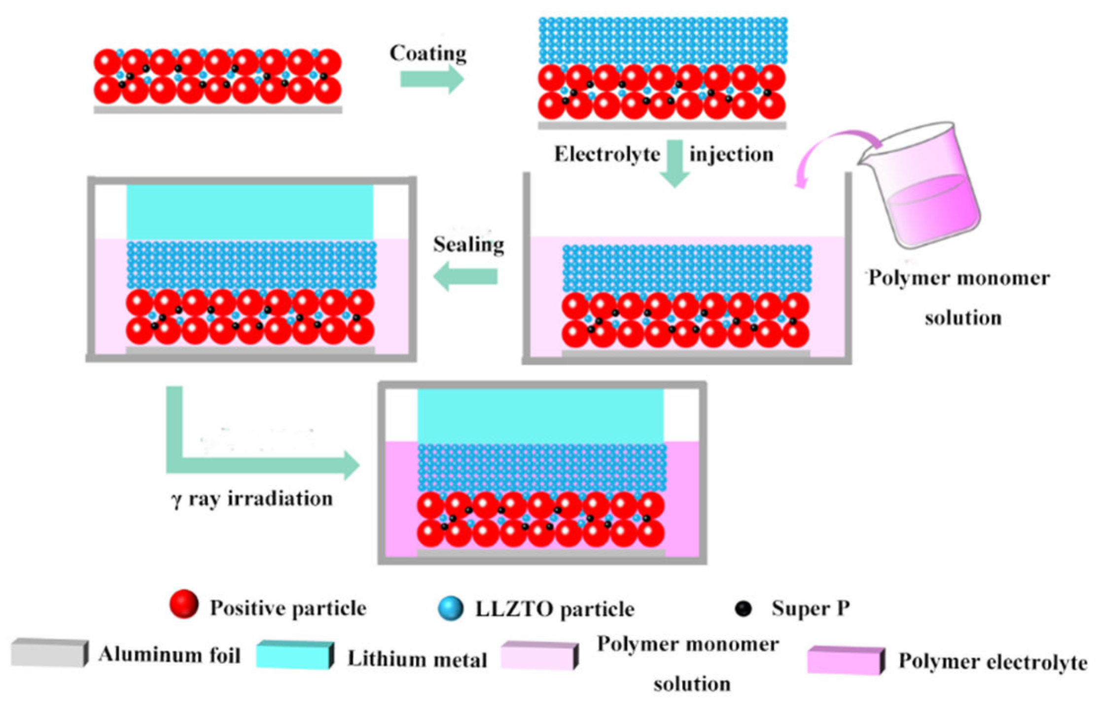
2.3. Preparation of In Situ Solidification Batteries

Scheme 1 shows the preparation process for the in situ solidification of batteries by γ−ray irradiation. The cathode materials LCO, LLZTO, and Super P were milled by hand in the weight ratio of 7:1:1 for 20 min. Then, PVDF binder accounting for 10% of the total mass and an optimum amount of solvent N−methyl pyrrolidone (NMP) were added and further mixed to form a homogeneous slurry. After the acquired slurry was cast onto the aluminum foil, the cathode sheet was transferred to a vacuum oven, where it was dried at 80 °C for 24 h to completely remove the NMP. Subsequently, LLZTO acetonitrile slurry containing 5% PEO binder was coated on the surface of the cathode and aluminum foil to prepare a composite cathode and LLZTO sheet. The composite cathode and LLZTO sheet were transferred to a vacuum oven at 60 °C for 24 h to completely remove the solvent. The prepared composite cathode plate was cut into 14 mm cathode sheets. The porosity of the cathode electrode was 25.8%, and the porosity of the composite cathode was 30.2%. The loading of active material on the cathode sheet was approximately 2 mg/cm2.
Button batteries are composed of polymer monomer−lithium salt solution, Li metal sheets, and composite cathode sheets. A pressure of 50 MPa was applied during the process of assembling the battery. Batteries were placed in an iron box and sent into the irradiation chamber containing a 60Co γ−ray radiation source by a conveyor belt. The radiation dose received by batteries was controlled according to the number of conveyor belt rotations, with a dose of 2 kGy per rotation, to complete the in situ solidification of the batteries.

2.4. Material Characterization

2.4.1. Physical Characterization

Wettability between polymer monomer and LCO cathode sheet was shown through a Powereach JC2000C1 contact goniometer. Thermogravimetric (TG) analysis was employed with a Model STA 449 instrument for the aim of exploring the optimal irradiation dose for the preparation of in situ cured cells with a heating rate of 5 K/min ramping up from 25 °C to a final temperature of 600 °C. A Fourier transform infrared Nicolet IS5 spectrometer (FT−IR) was employed to analyze whether the monomer VC was fully polymerized. The XRD pattern of LLZTO was obtained by a MiniFlex600 X−ray powder diffractometer (Cu−Kα, 40 KV,15 mA, 5°/min). Analysis of the degree of polymerization of monomer VC was carried out using 1H nuclear magnetic resonance spectra, which were obtained using a Bruker 500 MHz instrument. The Universal Material Testing Machine (UTM−4000, SUNS) was employed to test the mechanical stability of the LLZTO−PVC electrolyte. The surface and cross−sectional morphology, as well as element distribution of composite electrodes, were investigated using a Zeiss Gemini SEM 500 scanning electron microscope (SEM) and energy−dispersive X−ray spectroscopy (EDS). The in situ solidification of batteries was accomplished by a γ−ray generator (GM−08−03−A1, Beijing Gamma High−Tech Co., Ltd. Beijing, China).

2.4.2. Electrochemical Characterization

Electrochemical impedance spectroscopy (EIS) performed on a Solartron SI−1260 electrochemical workstation was used to test the ionic conductivity of LLZTO−PVC electrolyte by assembling blocking cells with an amplitude voltage of 10 mV and frequency range spanning from 0.1 Hz to 105 Hz. The ionic conductivity of LLZTO−PVC electrolyte was determined using Equation (1):
σ = d/(Rb × A)
where σ represents the electrolyte membrane’s ionic conductivity, Rb refers to bulk resistance, A denotes the surface area of the stainless steel (SS), and d is the thickness of the solid−state electrolyte.
To evaluate the electrochemical stability of the LLZTO−PVC electrolyte, liner scanning voltammetry (LSV) was performed using an electrochemical workstation (CHI660E). The asymmetric cell of Li/LLZTO−PVC/SS was assembled to measure between 2 and 6 V with a scan rate of 0.1 mV/s. The alternating current (AC) impedance was used to measure the internal interfacial contact of the LCO half−cell with a range from 0.1 Hz to 105 Hz on an electrochemical workstation (Solartron SI−1260). Under a current density of 0.2 C, cycle tests of the LCO half−cell and the LiFePO4 half−cell were conducted on the Xinwei battery test system. The charging and discharging range of the LCO half−cell is between 3.0 V and 4.3 V, and that of the LiFePO4 half−cell is between 2.5 V and 3.8 V (vs. Li/Li+). The Solartron SI−1260 electrochemical workstation was conducted to test the AC impedance of the LCO half−cell at different cycles with a range from 0.1 Hz to 105 Hz. All electrochemical tests were conducted at room temperature.

3. Results and Discussion

To achieve ASSBs with an excellent performance, the polymer monomer must meet the following conditions [41]: (1) they must possess functional groups such as a double bond or epoxy group for polymerization; (2) they must not generate by−product end groups such as −OH, −NH2 and −SH, as these would produce active hydrogen under irradiation conditions; (3) both the monomer and its polymerization product must have good wettability with the electrode material; (4) the lithium salts must have high solubility; (5) it must have groups capable of conducting lithium ions in solid−state, such as −EO−, C=O, and C≡N. In order to meet the above requirements, we chose four polymer monomers for testing, of which the structure is shown in Figure 1a. First of all, the wettability of the four polymer monomers with the LCO cathode material is tested by the contact angle test. The contact angle values of VC, PEGDMA (480), PEGDA (250), and PEGDGE (480) with LCO, as shown in Figure 1b, are 15.2°, 10.5°,11.3° and 19.9°, respectively. This shows that the four polymer monomers have good wettability with the LCO cathode material, while PEGDGE has a slightly poorer wettability due to its higher viscosity. Higher viscosity liquids show larger contact angles because stronger intermolecular forces between molecules make it harder for them to wet the electrode surface, leading to larger contact angles. Conversely, lower viscosity liquids show smaller contact angles because they can more easily flow and wet electrode surfaces. The photographs of the four polymer monomers after γ−irradiation polymerization are shown in Figure 1c. VC, PEGDA and PEGDMA all accomplish solidification of polymerization after γ−ray irradiation, while the product of PEGDGE after γ−ray radiation shows a gel−like appearance with residual droplets, indicating an incomplete polymerization reaction. This is due to the fact that the epoxy group of PEGDGE is not suitable for in situ solidification by radiation polymerization. The ring−opening reaction of the epoxy functional group belongs to the ionic polymerization reaction, while irradiation polymerization is more suitable for free−radical−type polymerization [42,43]. However, the mechanism of the free radical radiation polymerization of olefins has been well explored, so it is possible to achieve the in situ polymerization of VC, PEGDA and PDGDMA by γ−ray radiation polymerization.
The ionic conductivity is considered a crucial property for solid−state electrolytes. As shown in Figure S1, the XRD pattern of LLZTO powder demonstrates that the crystalline phase of LLZTO is a cubic phase. The LLZTO layer exhibits a significant impedance, which is caused by the point contacts between most LLZTO particles in Figure S2. Therefore, the electrolyte solution of VC, PEGDMA, and PEGDA with LiTFSI (20 wt%) is formulated to screen for suitable polymer monomers for the preparation of composite solid−state electrolytes, respectively. The LLZTO sheet and the above−mentioned electrolyte are assembled to form a blocking cell, and the AC impedance is tested after polymerization with a γ−ray radiation dose of 50 kGy. The SEM cross−sectional view of the LLZTO sheet is shown in Figure S3. The thickness of the LLZTO layer coated on the aluminum foil is 12 um. The test results of the impedance values of VC, PEGDMA, and PEGDA before and after irradiation are presented in Figure 2a,b. The impedance values of VC, PEGDMA, and PEGDA are 1.25 Ω, 21.2 Ω, and 25.3 Ω before irradiation, and after irradiation, the impedance values of VC, PEGDMA and PEGDA are 5.1 Ω, 575 Ω, and 593 Ω, which indicates that VC demonstrates the highest ionic conductivity both before and after polymerization. The impedance values have been compiled in Table S1. This is attributed to the small molecular weight and low viscosity of VC, which can easily penetrate the gaps of LLZTO particles and fill the entire solid electrolyte. In contrast, PEGDMA and PEGDA have a certain molecular weight and higher viscosity compared with VC, which are less likely to penetrate into LLZTO particles and form a homogeneous electrolyte. In addition, PEGDA and PEGDMA are prone to cross−linking within the molecular chain under high−energy γ−ray irradiation, forming part of the internal cross−linked high molecular polymer, which severely impairs lithium−ion migration. Restriction of the polymer chain segment’s movement due to intramolecular chain cross−linking will lead to a decrease in the ionic conductivity of the polymer electrolytes. This is because the mobility of polymer chain segments is essential for the conduction of lithium ions in the polymer solid−state electrolyte [44]. While VC is less likely to turn into intramolecular cross−linking because of the five−membered ring’s significant internal resistance impact, linear PVC has a more favorable chain segment movement for promoting Li+ conduction. As a result, the LLZTO−PVC electrolyte has a higher ionic conductivity.
Figure 3a shows the results of the thermogravimetric analysis of VC after different irradiation doses. It can be observed that the thermal weight loss of the irradiated samples before 280 °C decreases with increasing irradiation dose in the range of 10–50 kGy, which are 65.3%, 45.8%, 26.8%, 19.9% and 11.0%, respectively. This indicates that as the irradiation dose increases, the polymerization reaction becomes more complete, and the residual amount of VC and the low molecular weight PVC is lessened. However, the thermal stability of the irradiated product decreases, and the thermal weight loss rate before 280 °C increases to 13.5% when the irradiation dose is further increased. This is a result of overexposure to radiation, which will cause the PVC produced by in situ γ−ray radiation polymerization to degrade, resulting in a decrease in heat resistance. In addition, a large amount of VC remains unreacted under the irradiation dose of 10–30 kGy according to the results of thermogravimetric analysis, while the VC has completely reacted under the irradiation dose of 50 kGy. Therefore, the ideal radiation dose to initiate the polymerization of VC into PVC is 50 kGy. In order to verify the polymerization of VC after γ−ray irradiation, the structure of VC before and after irradiation was analyzed by FTIR. As shown in Figure 3b, the absorption peak at 3162 cm−1 and 906 cm−1 matches up with the vibrational absorption and out−of−plane swing of the =C−H. In addition, the absorption peak at 1705–1900 cm−1 corresponds to the vibrational absorption of C=O in VC. It is noteworthy that the C=O vibrational absorption peak of the VC is split due to the double frequency peak of the out−of−plane rocking of the =C−H olefin. The absorption peak at 1565 cm−1 is attributed to C=C vibrational absorption in the VC five−membered ring molecule, and 1160 cm−1 and 1102 cm−1 coincide with the vibrational absorption peaks of C−O−C. After γ−ray irradiation polymerization, the vibrational absorption peak at 3162 cm−1, 906 cm−1 and 1565 cm−1 all disappeared, which demonstrates that VC has been completely transformed into PVC after exposure to γ−rays. Moreover, after irradiation, the peak of C=O does not split due to the disappearance of =C−H, which further proves the formation of PVC [45,46,47]. Nuclear magnetic resonance spectroscopy (1H NMR) was studied on VC before and after irradiation in order to further confirm that VC was completely transformed into PVC. The result is shown in Figure 3c. The solvent is DMSO−d6, and the results were consistent with the literature [48], with the proton hydrogen of the VC at 7.82 ppm. After γ−ray irradiation, the spectral peak at 7.82 vanishes, and a new peak appears at 5.37 ppm, which confirms the successful polymerization of PVC.
To observe the microstructure of the composite cathode, the surface morphology of the LCO−LLZTO composite cathode (before irradiation) and LCO−LLZTO−PVC composite cathode (after irradiation) was characterized by SEM and EDS. As depicted in Figure 4a, LLZTO particles are uniformly coated on the LCO materials. The thickness of the cathode electrode is about 15 μm, and the thickness of the ceramic layer is about 12 μm. Obvious gaps among the LLZTO could be observed, which is very unfavorable for the conduction of lithium ions. Meanwhile, the elemental distribution of Zr indicates that LLZTO is uniformly distributed on the LCO cathode from EDS. As is presented in Figure 4b, it is apparent that the VC solution added could penetrate the LLZTO gaps and form a dense and uniform surface morphology after in situ irradiation polymerization, which is important for the construction of a good electrode interface to realize the rapid movement of lithium ions in the battery system. The EDS mapping reveals a uniform distribution of elements on the surface of the electrode after irradiation, in which the content of the Zr element decreases, and the contents of the C and O elements increase. This indicates that the VC solution achieves uniform in situ polymerization in the composite electrode and proves that we have successfully designed a uniform and dense composite solid electrolyte after γ−ray irradiation. To further prove that an integrated electrode interface is formed inside the battery after irradiation polymerization, the cross−section morphology of the LCO−LLZTO composite cathode (before irradiation) and the LCO−LLZTO−PVC composite cathode (after irradiation) was characterized by SEM. As illustrated in Figure 4c, the cross−section of the composite cathode with a clear gap between LLZTO and LCO particles before irradiation polymerization and the contact among particles occurs mostly through point contact. On the contrary, a compact and continuous three−dimensional continuous path is formed after in situ irradiation polymerization of the introduced VC solution in Figure 4d. It can also be demonstrated that an excellent interface is formed inside the cell after γ−ray irradiation polymerization compared with the cross−section of the cell before and after irradiation. The integrated electrode interface is essential for the transport of lithium ions.
The mechanical strength and flexibility of composite solid electrolytes are crucial for the large−scale production of ASSBs. Figure 5a shows the bending diagram of the PVC membrane. It is clear that the PVC membrane has excellent flexibility and mechanical strength, and it can be twisted and folded in any direction. Figure 5b illustrates the bending figure of the LLZTO−PVC electrolyte polymerized by γ−ray irradiation, which is made by adding the VC solution into the LLZTO sheets. Therefore, it is apparent that the LLZTO−PVC electrolyte also possesses excellent mechanical strength and flexibility and can be bent at a certain angle without fracture. To further characterize the good mechanical robustness of the PVC−LLZTO electrolyte prepared by irradiation polymerization, tensile strength was tested. Figure 5c illustrates that the maximum tensile strength of the produced PVC is as high as 87.8 MPa, which is comparable to the mechanical strength of commercial polyolefin separators. It is rather tough and has an elongation at break of 6.7%. The tensile strength test results show that the LLZTO−PVC electrolyte prepared by irradiation polymerization possesses excellent mechanical strength and flexibility.
Ion transport across the interface strongly correlates with the electrolyte’s ionic conductivity. LLZTO−PVC electrolyte with different lithium salt concentrations before and after γ−ray irradiation was tested by AC impedance at room temperature in order to investigate the effect of lithium salt concentrations on the ionic conductivity. Figure 6a,b shows the AC impedance spectra of the LLZTO−PVC electrolyte with different concentrations before and after γ−ray irradiation. Before irradiation polymerization, the impedance values of LLZTO−PVC electrolyte with LiTFSI concentrations of 10 wt%, 20 wt% and 30 wt% are 1.34 Ω, 1.25 Ω and 2.1 Ω, respectively. After irradiation polymerization, the impedance values of LLZTO−PVC electrolyte with LiTFSI concentrations of 10 wt%, 20 wt% and 30 wt% are 6.5 Ω, 5.1 Ω and 35.2 Ω, respectively. The impedance values have been compiled in Table S2. It is feasible to achieve the highest ionic conductivity of 1.2 × 10⁻⁴ S cm−1 at 25 °C when the lithium salt concentration is 20 wt%. The low concentration of lithium salt results in a low carrier concentration, which leads to a decrease in ionic conductivity. On the contrary, the interaction between lithium ions and polymer segments becomes stronger when the lithium salt concentration is too high, which limits the polymer chain segment movement. Therefore, the highest ionic conductivity of LLZTO−PVC electrolyte is achieved when the lithium salt concentration is 20 wt%. As shown in Figure S4, the ionic conductivity of LLZTO−PVC electrolyte with 20 wt% LiTFSI concentration is tested at variable temperatures, and the migration activation energy of lithium ions is 4.6 kJ/mol according to the Arrhenius equation.
To investigate the interfacial contact of the batteries before and after irradiation, LCO/LLZTO−PVC/Li half−cells with different lithium salt concentrations before and after γ−ray irradiation were tested by AC impedance at room temperature. Figure 6c,d shows the room temperature impedance test results of the LCO/LLZTO−PVC/Li half−cells before and after irradiation. Before irradiation polymerization, the impedance of LCO/LLZTO−VC/Li half−cells with LiTFSI concentrations of 10 wt%, 20 wt% and 30 wt% was 61.0 Ω, 60.1 Ω and 173.2 Ω, respectively. The impedance values of half−cells with lithium salt concentrations of 10 wt% and 20 wt% are comparable to the liquid electrolyte system, indicating that VC can effectively wet the LLZTO and LCO particles and eliminate the interfacial impedance. After in situ irradiation polymerization, the impedance of LCO/LLZTO−PVC/Li half−cells with LiTFSI concentrations of 10 wt%, 20 wt%, and 30 wt% increases to 136.2 Ω, 89.1 Ω, and 718.3 Ω, respectively. The impedance values have been compiled in Table S3. Similar to the ionic conductivity test results, the LLZTO−PVC electrolyte with 20 wt% LiTFSI concentration has the best cell performance with a room temperature impedance value of only 89.1 Ω, which indicates that the in situ γ−ray irradiation polymerization can effectively eliminate the poor interfacial contact and reduce the cell interfacial impedance.
One of the fundamental requirements for solid−state electrolytes is to maintain electrochemical stability under typical battery operating conditions. The LSV test of the LLZTO−PVC electrolyte was performed at a scan rate of 0.1 mV/s, as presented in Figure 7a. The test findings reveal that the electrochemical window of the LLZTO−PVC electrolyte exceeds 4.65 V (vs. Li+/Li), which is compatible with the majority of the present cathode materials for high−voltage systems. The electrochemical performance of the LCO/LLZTO−PVC/Li half−cell irradiated by γ−ray irradiation was tested at room temperature. The irradiated LCO/LLZTO−PVC/Li half−cell irradiated by γ−ray irradiation exhibited a satisfactory cycling performance under the high voltage of 4.3 V at a current density of 0.2 C at 25 °C, as depicted in Figure 7b,c. Specifically, the capacity retention of LCO/LLZTO−PVC/Li half−cell is 92.4% over 100 cycles running at a current density of 0.2 C with a Coulombic efficiency of 98%. After 100 cycles, the LCO half−cell still retains a capacity of 128.3 mAh/g. The cycling performance of the LiFePO4/LLZTO−PVC/Li half−cell was also tested, as shown in Figure S5. The LiFePO4 half−cell irradiated by γ−rays could stably run at a rate of 0.2 C over 100 cycles at 25 °C, with a capacity retention of 97.3%. As is shown in Figure 7d, the impedance of the LCO half−cell is tested for different numbers of cycles in order to characterize the internal interface of the cell. The impedance of LCO half−cells does not significantly rise as the number of cycles increases, which shows that a good interface has been established inside the battery.

4. Conclusions

In summary, we have developed a new type of in situ solid−state battery based on LLZTO−PVC electrolyte by means of in situ γ−ray irradiation polymerization. By combining the excellent ionic conductivity of ceramic electrolytes and the good interfacial properties and flexibility of polymer electrolytes, the LLZTO−PVC electrolyte exhibits a high ionic conductivity (1.2 × 10⁻⁴ S cm−1 at 25 °C) with good mechanical robustness and flexibility. The electrochemical window of LLZTO−PVC electrolyte exceeds 4.65 V (vs. Li+/Li). The LCO half−cell irradiated by γ−rays can steadily run over 100 cycles under a high voltage of 4.3 V and at a current density of 0.2 C at 25 °C), with a capacity retention of 92.4%. Additionally, the in situ γ−ray irradiation polymerization method can greatly simplify the assembly process of solid−state batteries, making it possible to apply this method to the preparation of future large−scale solid−state lithium−ion batteries.

Supplementary Materials

The following supporting information can be downloaded at: https://www.mdpi.com/article/10.3390/batteries9050255/s1, Figure S1: XRD pattern of LLZTO and corresponding standard card. Figure S2. The AC impedance spectra of the LLZTO layer at room temperature. Figure S3: The SEM cross−sectional view of LLZTO sheet. Figure S4: (a) Different temperature AC impedance spectra of LLZTO−PVC electrolyte with 20 wt% LiTFSI concentration. (b) Arrhenius plots of LLZTO−PVC electrolyte with 20 wt% LiTFSI concentration. Figure S5: (a) Cycle performance of LiFePO4/LLZTO−PVC/Li half−cell at 0.2 C. (b) Charge and discharge curves of LiFePO4/LLZTO−PVC/Li half−cell for various cycles. Table S1: Impedance values of LLZTO with different polymer monomers before and after irradiation. Table S2: Impedance values of LLZTO−PVC with different LiTFSI mass fractions before and after irradiation. Table S3: Impedance values of assembled LCO half−cells with LLZTO−PVC containing different LiTFSI mass fractions before and after irradiation.

Author Contributions

Conceptualization, Z.C. and P.Z.; methodology, P.Z.; validation, X.Y., N.P. and J.Z.; formal analysis, J.Z.; investigation, R.L.; resources, J.Z.; data curation, Z.C.; writing—original draft preparation, Z.C.; writing—review and editing, X.Y.; visualization, X.Y.; supervision, Y.Z.; project administration, Z.C.; funding acquisition, P.Z. and Z.C. All authors have read and agreed to the published version of the manuscript.

Funding

This research was funded by the National Key Research and Development Program of China (grant number 2021YFB2400300), the National Natural Science Foundation of China (grant number 21875195, 22021001), Fundamental Research Funds for the Central Universities (grant number 20720190040), and the Key Research and Development Program of Yunnan Province (grant number 202103AA080019).

Data Availability Statement

Not applicable.

Acknowledgments

The authors would like to express their heartfelt appreciation for the invaluable assistance and support provided by the Tan Kah Kee Innovation Laboratory.

Conflicts of Interest

The authors declare no conflict of interest.

References

  1. Zhao, J. Changing our lives and building the foundation of society—The dramatic competition for R&D behind the Nobel Prize. J. Electrochem. 2019, 25, 616–620. [Google Scholar] [CrossRef]
  2. Goodenough, J.B. Electrochemical energy storage in a sustainable modern society. Energy Environ. Sci. 2014, 7, 14–18. [Google Scholar] [CrossRef]
  3. Deng, D. Li-ion batteries: Basics, progress, and challenges. Energy Sci. Eng. 2015, 3, 385–418. [Google Scholar] [CrossRef]
  4. Xia, S.; Wu, X.; Zhang, Z.; Cui, Y.; Liu, W. Practical challenges and future perspectives of all-solid-state lithium-metal batteries. Chem 2019, 5, 753–785. [Google Scholar] [CrossRef]
  5. Tan, S.-J.; Zeng, X.-X.; Ma, Q.; Wu, X.-W.; Guo, Y.-G. Recent advancements in polymer-based composite electrolytes for Rechargeable Lithium Batteries. Electrochem. Energy Rev. 2018, 1, 113–138. [Google Scholar] [CrossRef]
  6. Wu, J.; Yuan, L.; Zhang, W.; Li, Z.; Xie, X.; Huang, Y. Reducing the thickness of solid-state electrolyte membranes for high-energy lithium batteries. Energy Environ. Sci. 2021, 14, 12–36. [Google Scholar] [CrossRef]
  7. Eglitis, R.I.; Borstel, G. Towards a practical rechargeable 5 V Li ion battery. Phys. Stat. Sol. A 2005, 202, R13–R15. [Google Scholar] [CrossRef]
  8. Eglitis, R.I. Theoretical prediction of the 5 V rechargeable Li ion battery using Li2CoMn3O8 as a cathode. Phys. Scr. 2015, 90, 094012. [Google Scholar] [CrossRef]
  9. York, M.; Larson, K.; Harris, K.C.; Carmona, E.; Albertus, P.; Sharma, R.; Noked, M.; Strauss, E.; Ragones, H.; Golodnitsky, D. Recent advances in solid-state beyond lithium batteries. J. Solid State Electrochem. 2022, 26, 1851–1869. [Google Scholar] [CrossRef]
  10. Guo, B.; Fu, Y.; Wang, J.; Gong, Y.; Zhao, Y.; Yang, K.; Zhou, S.; Liu, L.; Yang, S.; Liu, X.; et al. Strategies and characterization methods for achieving high performance PEO-based solid-state lithium-ion batteries. Chem. Commun. 2022, 58, 8182–8193. [Google Scholar] [CrossRef]
  11. Wu, B.; Chen, C.; Danilov, D.L.; Eichel, R.-A.; Notten, P.H.L. All-solid-state thin film Li-ion batteries: New challenges, new materials, and new designs. Batteries 2023, 9, 186. [Google Scholar] [CrossRef]
  12. Wang, X.; Hua, H.; Xie, X.; Zhang, P.; Zhao, J. Hydroxyl on the filler surface promotes Li+ conduction in PEO all-solid-state electrolyte. Solid State Ionics 2021, 372, 115768. [Google Scholar] [CrossRef]
  13. Bai, L.; Li, E.; Du, Z.; Yuan, S. Structural changes of PMMA substrates with different electrolyte solutions: A molecular dynamics study. Colloids Surf. A Physicochem. Eng. Asp. 2017, 522, 51–57. [Google Scholar] [CrossRef]
  14. Zhang, X.; Liu, T.; Zhang, S.; Huang, X.; Xu, B.; Lin, Y.; Xu, B.; Li, L.; Nan, C.-W.; Shen, Y. Synergistic Coupling between Li6.75La3Zr1.75Ta0.25O12 and poly(vinylidene fluoride) induces high ionic conductivity, mechanical strength, and thermal stability of solid composite electrolytes. J. Am. Chem. Soc. 2017, 139, 13779–13785. [Google Scholar] [CrossRef]
  15. Mindemark, J.; Lacey, M.J.; Bowden, T.; Brandell, D. Beyond PEO—Alternative host materials for Li +-conducting solid polymer electrolytes. Prog. Polym. Sci. 2018, 81, 114–143. [Google Scholar] [CrossRef]
  16. Zhou, Q.; Ma, J.; Dong, S.; Li, X.; Cui, G. Intermolecular chemistry in solid polymer electrolytes for high-energy-density lithium batteries. Adv. Mater. 2019, 31, e1902029. [Google Scholar] [CrossRef]
  17. Famprikis, T.; Canepa, P.; Dawson, J.A.; Islam, M.S.; Masquelier, C. Fundamentals of inorganic solid-state electrolytes for batteries. Nat. Mater. 2019, 18, 1278–1291. [Google Scholar] [CrossRef]
  18. Murugan, R.; Thangadurai, V.; Weppner, W. Fast lithium ion conduction in garnet-type Li7La3Zr2O12. Angew.Chem. Int. Ed. 2007, 46, 7778–7781. [Google Scholar] [CrossRef]
  19. Reddy, I.N.; Akkinepally, B.; Reddy, C.V.; Sreedhar, A.; Ko, T.J.; Shim, J. A systematic study of annealing environment and Al dopant effect on NASICON-type LiZr2(PO4)3 solid electrolyte. Ionics 2020, 26, 4287–4298. [Google Scholar] [CrossRef]
  20. Kato, Y.; Hori, S.; Kanno, R. Li10GeP2S12-type superionic conductors: Synthesis, structure, and ionic transportation. Adv. Energy Mater. 2020, 10, 2002153. [Google Scholar] [CrossRef]
  21. Akkinepally, B.; Reddy, I.N.; Ko, T.J.; Yoo, K.; Shim, J. Dopant effect on Li+ ion transport in NASICON-type solid electrolyte: Insights from molecular dynamics simulations and experiments. Ceram. Int. 2022, 48, 12142–12151. [Google Scholar] [CrossRef]
  22. Fu, S.; Arinicheva, Y.; Hüter, C.; Finsterbusch, M.; Spatschek, R. Grain boundary characterization and potential percolation of the solid electrolyte LLZO. Batteries 2023, 9, 222. [Google Scholar] [CrossRef]
  23. Pan, J.; Zhao, P.; Wang, N.; Huang, F.; Dou, S. Research progress in stable interfacial constructions between composite polymer electrolytes and electrodes. Energy Environ. Sci. 2022, 15, 2753–2775. [Google Scholar] [CrossRef]
  24. Park, K.; Yu, B.-C.; Jung, J.-W.; Li, Y.; Zhou, W.; Gao, H.; Son, S.; Goodenough, J.B. Electrochemical nature of the cathode interface for a solid-state lithium-ion battery: Interface between LiCoO2 and garnet-Li7La3Zr2O12. Chem. Mater. 2016, 28, 8051–8059. [Google Scholar] [CrossRef]
  25. Yang, X.; Liu, J.; Pei, N.; Chen, Z.; Li, R.; Fu, L.; Zhang, P.; Zhao, J. The critical role of fillers in composite polymer electrolytes for lithium battery. Nanomicro Lett. 2023, 15, 74. [Google Scholar] [CrossRef] [PubMed]
  26. Vijayakumar, V.; Anothumakkool, B.; Kurungot, S.; Winter, M.; Nair, J.R. In situ polymerization process: An essential design tool for lithium polymer batteries. Energy Environ. Sci. 2021, 14, 2708–2788. [Google Scholar] [CrossRef]
  27. Lu, J.; Zhou, J.; Chen, R.; Fang, F.; Nie, K.; Qi, W.; Zhang, J.-N.; Yang, R.; Yu, X.; Li, H.; et al. 4.2V poly(ethylene oxide)-based all-solid-state lithium batteries with superior cycle and safety performance. Adv. Energy Mater. 2020, 32, 191–198. [Google Scholar] [CrossRef]
  28. Zeng, Y.; Yang, J.; Shen, X.; Li, R.; Chen, Z.; Huang, X.; Zhang, P.; Zhao, J. New UV-initiated lithiated-interpenetrating network gel-polymer electrolytes for lithium-metal batteries. J. Power Sources. 2022, 541, 231681. [Google Scholar] [CrossRef]
  29. Liu, M.; Xie, W.; Li, B.; Wang, Y.; Li, G.; Zhang, S.; Wen, Y.; Qiu, J.; Chen, J.; Zhao, P. Garnet Li7LaZr2O12-based solid-state lithium batteries achieved by in situ thermally polymerized gel polymer electrolyte. ACS Appl. Mater. Interfaces 2022, 14, 43116–43126. [Google Scholar] [CrossRef]
  30. D’Angelo, A.J.; Panzer, M.J. Enhanced lithium ion transport in poly(ethylene glycol) diacrylate-supported solvate ionogel electrolytes via chemically cross-linked ethylene oxide pathways. J. Phys. Chem. B. 2017, 121, 890–895. [Google Scholar] [CrossRef]
  31. Ryou, M.-H.; Lee, Y.M.; Cho, K.Y.; Han, G.-B.; Lee, J.-N.; Lee, D.J.; Choi, J.W.; Park, J.-K. A gel polymer electrolyte based on initiator-free photopolymerization for lithium secondary batteries. Electrochim. Acta 2012, 60, 23–30. [Google Scholar] [CrossRef]
  32. Suk, J.; Lee, Y.H.; Kim, D.Y.; Kim, D.W.; Cho, S.Y.; Kim, J.M.; Kang, Y. Semi-interpenetrating solid polymer electrolyte based on thiol-ene cross-linker for all-solid-state lithium batteries. J. Power Sources 2016, 334, 154–161. [Google Scholar] [CrossRef]
  33. Kim, S.-H.; Choi, K.-H.; Cho, S.-J.; Park, J.-S.; Cho, K.Y.; Lee, C.K.; Lee, S.B.; Shim, J.K.; Lee, S.-Y. A shape-deformable and thermally stable solid-state electrolyte based on a plastic crystal composite polymer electrolyte for flexible/safer lithium-ion batteries. J. Mater. Chem. A 2014, 2, 10854–10861. [Google Scholar] [CrossRef]
  34. Nair, J.R.; Destro, M.; Bella, F.; Appetecchi, G.B.; Gerbaldi, C. Thermally cured semi-interpenetrating electrolyte networks (s-IPN) for safe and aging-resistant secondary lithium polymer batteries. J. Power Sources 2016, 306, 258–267. [Google Scholar] [CrossRef]
  35. Lee, K.-P.; Gopalan, A.I.; Santhosh, P.; Lee, S.H.; Nho, Y.C. Gamma radiation induced distribution of gold nanoparticles into carbon nanotube-polyaniline composite. Compos. Sci. Technol. 2007, 67, 811–816. [Google Scholar] [CrossRef]
  36. Xu, Z.; Chen, L.; Zhou, B.; Li, Y.; Li, B.; Niu, J.; Shan, M.; Guo, Q.; Wang, Z.; Qian, X. Nano-structure and property transformations of carbon systems under γ-ray irradiation: A review. RSC Adv. 2013, 3, 154g. [Google Scholar] [CrossRef]
  37. Baek, M.; Kim, J.; Jin, J.; Choi, J.W. Photochemically driven solid electrolyte interphase for extremely fast-charging lithium-ion batteries. Nat. Commun. 2021, 12, 6807. [Google Scholar] [CrossRef]
  38. Hasanain, F.; Guenther, K.; Mullett, W.M.; Craven, E. Gamma sterilization of pharmaceuticals-a review of the irradiation of excipients, active pharmaceutical ingredients, and final drug product formulations. PDA J. Pharm. Sci. Technol. 2014, 68, 113–137. [Google Scholar] [CrossRef]
  39. Rouif, S. Radiation cross-linked polymers: Recent developments and new applications. Nucl. Instrum. Methods Phys. Res. B 2005, 236, 68–72. [Google Scholar] [CrossRef]
  40. Shen, X.; Zeng, Y.Z.; Li, R.; Zhang, P.; Zhao, J. In situ solidification of flame-retardant lithium-ion batteries by γ-ray irradition. Energy Storage Sci. Technol. 2022, 11, 1816–1821. [Google Scholar] [CrossRef]
  41. Murray, K.A.; Kennedy, J.E.; McEvoy, B.; Vrain, O.; Ryan, D.; Cowman, R.; Higginbotham, C.L. Effects of gamma ray and electron beam irradiation on the mechanical, thermal, structural and physicochemical properties of poly (ether-block-amide) thermoplastic elastomers. J. Mech. Behav. Biomed. Mater. 2013, 17, 252–268. [Google Scholar] [CrossRef] [PubMed]
  42. Imperiyka, M.; Ahmad, A.; Hanifah, S.A.; Rahman, M.Y.A. Role of salt concentration lithium perchlorate on ionic conductivity and structural of (glycidyl methacrylate -co-ethyl methacrylate) (70/30) based on a solid polymer electrolyte. Adv. Mater. Res. 2012, 626, 454–458. [Google Scholar] [CrossRef]
  43. Lazauskaite, R.; Grazulevicius, J.V. Synthesis and cationic photopolymerization of electroactive monomers containing functional groups. Polym. Adv. Technol. 2005, 16, 571–581. [Google Scholar] [CrossRef]
  44. Armand, M.; Tarascon, J.M. Building better batteries. Nature 2008, 451, 652–657. [Google Scholar] [CrossRef]
  45. Tominaga, Y.; Yamazaki, K.; Nanthana, V. Effect of anions on lithium ion conduction in poly(ethylene carbonate)-based polymer electrolytes. J. Electrochem. Soc. 2015, 162, A3133–A3136. [Google Scholar] [CrossRef]
  46. Chai, J.; Liu, Z.; Ma, J.; Wang, J.; Liu, X.; Liu, H.; Zhang, J.; Cui, G.; Chen, L. In situ generation of poly (vinylene carbonate) based solid electrolyte with interfacial stability for LiCoO2 lithium batteries. Adv. Sci. 2017, 4, 1600377. [Google Scholar] [CrossRef]
  47. Ju, J.; Wang, Y.; Chen, B.; Ma, J.; Dong, S.; Chai, J.; Qu, H.; Cui, L.; Wu, X.; Cui, G. Integrated interface strategy toward room temperaturesolid-state lithium batteries. ACS Appl. Mater. Interfaces 2018, 10, 13588–13597. [Google Scholar] [CrossRef]
  48. Lameiras, P.; Nuzillard, J.M. Highly viscous binary solvents: DMSO-d6/glycerol and DMSO-d6/glycerol-d8 forpolar and apolar mixture analysis by NMR. Anal. Chem. 2016, 88, 4508–4515. [Google Scholar] [CrossRef]
Scheme 1. Schematic diagram of preparation process for in situ solidification of batteries by γ−ray irradiation.
Batteries 09 00255 sch001
Figure 1. Screening of polymer monomers. (a) Schematic structure of the four polymer monomers (b) Contact angle test of the four polymer monomers with LCO cathode material. (c) Photogram of the four polymer monomers after radiation polymerization at a dose of 50 kGy.
Batteries 09 00255 g001
Figure 2. Comparison of AC impedances of VC−20 wt% LiTFSI, PEGDMA−20 wt% LiTFSI, and PEGDA−20 wt% LiTFSI before (a) and after (b) irradiation.
Batteries 09 00255 g002
Figure 3. (a) Thermogravimetric analysis results of VC after different irradiation doses. (b) Infrared comparison of VC before and after irradiation. (c) Nuclear magnetic resonance spectra (1H NMR) test results of VC before and after irradiation.
Batteries 09 00255 g003
Figure 4. SEM morphology and EDS images of LCO−LLZTO composite cathode surface before irradiation (a) and LCO−LLZTO−PVC composite cathode surface after irradiation (b). SEM cross−sectional view of LCO−LLZTO composite cathode surface before irradiation (c) and LCO−LLZTO−PVC composite cathode surface after irradiation (d).
Batteries 09 00255 g004
Figure 5. (a) Bending optical photos of PVC film prepared by casting after irradiation and (b) bending photos of LLZTO−PVC electrolyte. (c) Tensile strength test of LLZTO−PVC electrolyte.
Batteries 09 00255 g005
Figure 6. The electrochemical impedance spectroscopy of LLZTO−PVC electrolyte before (a) and after (b) γ−ray radiation at room temperature. The electrochemical impedance spectroscopy of LCO/LLZTO−PVC/Li cell before (c) and after (d) γ−ray radiation at room temperature.
Batteries 09 00255 g006
Figure 7. Electrochemical performances of LCO/LLZTO−PVC/Li battery. Temperature: 25 °C. (a) The LSV curve of LLZTO−PVC electrolyte at a scan rate of 0.1 mV/s. (b) The 100−cycle performance of LCO/LLZTO−PVC/Li battery at 0.2 C. (c) Voltage profiles during charging and discharging of LCO/LLZTO−PVC/Li battery at 0.2 C. (d) AC impedance spectra of LCO/LLZTO−PVC/Li battery in different cycles.
Batteries 09 00255 g007
Disclaimer/Publisher’s Note: The statements, opinions and data contained in all publications are solely those of the individual author(s) and contributor(s) and not of MDPI and/or the editor(s). MDPI and/or the editor(s) disclaim responsibility for any injury to people or property resulting from any ideas, methods, instructions or products referred to in the content.

