Article

Prefabrication of a Lithium Fluoride Interfacial Layer to Enable Dendrite-Free Lithium Deposition

School of Automotive Studies & Clean Energy Automotive Engineering Center, Tongji University (Jiading Campus), Shanghai 201804, China
*
Authors to whom correspondence should be addressed.
Batteries 2023, 9(5), 283; https://doi.org/10.3390/batteries9050283
Submission received: 19 April 2023 / Revised: 16 May 2023 / Accepted: 19 May 2023 / Published: 22 May 2023

Abstract

:
Lithium metal is one of the most attractive anode materials for rechargeable batteries. However, its high reactivity with electrolytes, huge volume change, and dendrite growth upon charge or discharge lead to a low CE and the cycle instability of batteries. Due to the low surface diffusion resistance, LiF is conducive to guiding Li+ deposition rapidly and is an ideal component for the surface coating of lithium metal. In the current study, a fluorinated layer was prepared on a lithium metal anode surface by means of chemical vapor deposition (CVD). In the carbonate-based electrolyte, smooth Li deposits were observed for these LiF-coated lithium anodes after cycling, providing excellent electrochemical stability for the lithium metal anode in the liquid organic electrolyte. The CE of Li|Cu batteries increases from 83% for pristine Li to 92% for LiF-coated ones. Moreover, LiF-Li|LFP exhibits a decent rate and cycling performance. After 120 cycles, the capacity retention of 99% at 1C is obtained, and the specific capacity is maintained above 149 mAh/g. Our investigation provides a simple and low-cost method to improve the performance of rechargeable Li-metal batteries.

1. Introduction

Lithium metal has a high theoretical specific capacity (3860 mAh/g), a small weight density (0.534 g/cm3), and a low electrochemical potential (−3.040 V vs. a standard hydrogen electrode), making it a highly promising anode candidate for next-generation rechargeable batteries [1,2]. However, a number of obstacles must be overcome before its commercial applications. These include (1) the rapid and irreversible reaction between lithium metal and liquid-state electrolytes; (2) its uncontrolled lithium dendrite growth; (3) the huge volume of deformation of the lithium metal anode (LMA) during the charging and discharging process [3,4].
Due to the high reactivity of lithium, a rapid reaction occurs when it is in direct contact with liquid-state electrolytes, producing a thick and uneven solid electrolyte interface layer (SEI) on the surface of the lithium [5]. The uneven SEI can lead to the preferential formation of nucleation points, thereby propagating lithium dendrites. In the worst scenario, the sharp lithium dendrites will break the SEI [6], puncture the separator, cause a short circuit, and finally lead to a thermal runaway. The volume deformation of LMA will further lead to the rupture of the SEI and expose the new surface of lithium, degrading the battery performance in a vicious cycle [7,8,9]. Therefore, to solve the above problems, a number of research strategies have been developed, such as a surface coating on the lithium [10,11,12,13,14], developing new additives and solvents for electrolytes [15,16,17], and designing a composite separator with a coating layer [18,19,20,21]. Among these remedies, the preparation of an artificial interface layer on the surface of the lithium is the one of the most effective methods [22,23,24,25].
The joint density functional theoretical (JDFT) analysis showed that an SEI layer of lithium halide (e.g., LiF, LiCl, LiBr, and LiI) has a better stability and a faster diffusion rate (the surface diffusion barrier of adsorbed atoms is 0.03~0.15 eV) than the regular SEI components (e.g., LiOH, Li2O, and Li2CO3) [26]. LiF has a wide stability electrochemical window, a negligible solubility in most organic electrolytes, and the ability to adjust the surface tension. Furthermore, it has a high chemical stability with lithium and organic electrolyte materials [27,28,29]. Due to the low surface diffusion resistance, LiF is conducive to guiding Li+ deposition rapidly and is an ideal component for the surface coating of lithium [30,31]. As an effective interface layer, LiF has been confirmed to play an important role in achieving high-performance LMA [32,33,34]. The artificial LiF layer can be prepared by various methods. For example, lithium can directly react with a solution containing fluorine sources such as NH4HF2 to form a LiF surface coating [35,36]. Gaseous reactions such as the thermal decomposition of fluoropolymer CYTOP [37] and nonhazardous gaseous Freon R134a [27] and an atomic layer deposition (ALD) using TiF4 [38] or HF/pyridine [39], etc., are also frequently used to prepare LiF layers. In addition, other methods exist, such as thermal evaporation [40] or magnetron sputtering [41]. These LiF coatings smoothen Li deposits after cycling and provide an excellent electrochemical stability for the lithium metal anode in the liquid organic electrolytes. Most of the current methods to prepare LiF coatings are carried out in liquid and solid phases, which have the disadvantages of an uneven interface contact and the production of other by-products. In some cases, the required precursors are complex, and the reaction conditions are demanding, which is not conducive to scaling up for practical application.
In this investigation, we propose to fabricate LiF-coated Li Metal with a uniform surface and good Li+ diffusivity and chemical stability to restrain dendrite growth. The LiF layer was pre-fabricated on the surface of the lithium metal by chemical vapor deposition (CVD), where PVDF is pyrolyzed into HF and -[CH=CF]n- at a high temperature, and the released HF reacts with lithium to form LiF on the surface LMA at a low temperature. This simple method provides a feasible way to fabricate a uniform LiF coating on the surface of the LMA to homogenize the lithium nucleation [42] and inhibit the formation of lithium dendrites during charging and discharging. In comparison with the pristine LMA, the LiF-coated LMA presents a better rate capability and a higher cycling stability when it is paired with LFP electrodes.

2. Materials and Methods

2.1. Fabrication of LiF-Coated Li Metal

First, dry PVDF powder was loaded in an alumina crucible, which was transferred into the middle of the alumina tube and located in the center of the tubular furnace heating zone (MTI OTD-1200X)). Second, the tube was purged by argon, and the lithium chips were put into an alumina crucible in the glove box and quickly transferred into the alumina tube in a horizontal position and located 30 cm downstream from the PVDF powder. Afterwards, the argon flow rate was set at 50 mL/min, and the PVDF was heated to the target temperature of 400 °C at the ramp rate of 5 °C/min. After the reaction was carried out at 400 °C for 30 min, the tubular furnace was naturally cooled down to room temperature. Finally, the LiF-coated Li Metal was obtained. This was sealed and transferred into the glove box for electrochemical evaluation and characterization.

2.2. Material Characterizations

The thermal decomposition behavior of the PVDF was investigated by thermogravimetric analysis (TGA) and derivative thermogravimetry (DTG) on the thermal gravimetric analyzer (TA). The decomposition products of PVDF after heating were analyzed by Fourier transform infrared spectroscopy (FTIR) (Thermofisher, Waltham, MA, USA). The surface morphologies of the lithium chips were analyzed by a scanning electron microscopy (SEM) (ZEISS, Oberkochen, Germany), and elemental mapping was conducted on an energy-dispersive X-ray (EDX) spectrometer (Oxford Instruments, Abingdon, UK). An X-ray photoelectron spectroscopy (Bruker, Bremen, Germany) was used to identify the elemental chemical state and composition of the samples.

2.3. Electrochemical Evaluations

CR2032-type coin cells assembled in an argon-filled glove box were employed to evaluate the electrochemical performance of the tested cells. The battery types included the lithium copper half-cell (Li|Cu), the symmetrical cell (Li|Li), and the LFP half-cell (Li|LFP). Because copper foil cannot be coated by a LiF layer by means of the same method as that for lithium chips, single-sided laminated lithium (50 μm) copper foil (Li-Cu) was adopted in thisprocedure. Before testing, all the lithium on the Li-Cu electrode was stripped to the counter lithium anode in the Li|Li-Cu. For the Li|LFP, the LFP cathode was composed of LFP, Super-P, and PVDF as the active material, conductor, and binder, respectively. These were mixed according to the mass ratio of 8:1:1 and dispersed uniformly in N-methylpyrrolidone (NMP), employing a Thinky mixer to form a slurry. Afterwards, the evenly mixed slurry was coated on the aluminum foil by means of the classical doctor-bladed method. After the slurry was dried at 80 °C, a circular electrode disc with a diameter of 12 mm was punched. The mass loading of LFP in the whole electrode was about 4 mg/cm2. The electrolyte was 1 M LiPF6 dissolved in ethylene carbonate (EC)/diethyl carbonate (DEC) (1:1 volume ratio). To standardize the testing, 50 μL of electrolyte was utilized in each coin cell. Celgard 2400 was employed as the separator. All electrochemical tests were performed on the NEWARE battery tester system at 25 °C.

3. Results and Discussion

3.1. Fabrication and Characterizationof LiF-Coated Li

As shown in Figure 1a, PVDF powder was heated to the decomposition temperature under an atmosphere of argon. The released HF in the product was carried by the argon and reacted with lithium to form a LiF coating on the surface of the lithium chips. Figure 1b shows the TGA and DTG curves of PVDF. As can be seen from the figure, the weight loss accelerated gradually from around 320 °C and reached its peak at ~450 °C. This can be ascribed to the pyrolysis of the polymeric backbone -CH2-CF2- into -CH=CF- and HF at a high temperature [43,44,45]. To obtain a uniform surface, the decomposition reaction of PVDF needs to occur slowly. Therefore, the experimental temperature was selected as 400 °C according to the TGA-DTG curve. Figure 1c shows the FTIR spectra of PVDF powder before and after heating. The peaks at 1404 cm−1 and 1199 cm−1 correspond to the characteristic peaks of the C–F bonds and C–H bonds of PVDF, respectively. Compared to the original PVDF, the -CH=CH- characteristic peak appeared at 1612 cm−1 after 400 °C heat treatment, verifying the decomposition of PVDF. This is in line with our expectation that PVDF can decompose to HF and -[CH=CF]n- after thermal treatment at 400 °C.
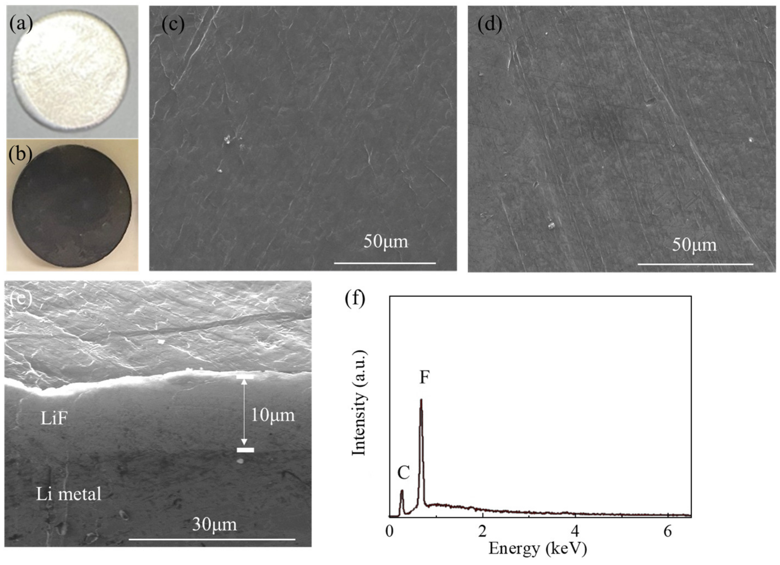
Figure 2a shows a pristine lithium chip with a smooth and metallic surface. Figure 2b presents the photo of a lithium plate after LiF coating. The surface is even and flat, and the surface color becomes dark gray. (All photos were taken in the glove box.) To better observe the structure, the top-view SEM images of the lithium surface before and after LiF coating are shown in Figure 2c,d. Note that the surface layer of the generated prefabricated layer is flat and compact. Figure 2e shows the cross-sectional SEM image of the lithium. The LiF layer and Li are closely bound, and no gap is observed. The thickness of the LiF layer is about 10 μm. Figure 2f shows the EDS spectrum of the surface of the LiF-coated LMA. Two characteristic peaks appear in the spectrum, which are identified as C and F, respectively. The ratio of F to C is quantified as 4:1. Therefore, it can be inferred that the F-Li may be composed of inorganic LiF along with a small amount of carbon-containing organic species. The XRD pattern of LiF-coated Li is provided in Figure S1. The peaks at 38.8°, 45.1°, 65.6°, and 78.9° were indexed to (111), (200), (220) and (311) planes of the LiF phase (JCPDS card no. 72-1538).
To further confirm the composition of the LiF coating, an XPS characterization was performed. Figure 3a shows the Li 1’s spectra XPS curve of the pristine lithium chip. The peak at 54.6 eV represents the metallic lithium bond in the Li 1’s XPS spectra curve of the pristine lithium chip. In addition, carbonate, hydroxide, and oxideare present and may come from the intrinsic Li surface or the XPS chamber. Figure 3b–d show the XPS curves of spectra Li 1s, C 1s and F1s on the surface of the LiF-coating, respectively. In Figure 3b, the peak position at 55.7 eV is attributed to the Li-F bond. In Figure 3c, the fitted C1 peaks are deconvoluted into three peaks at 286.1 eV, 285 eV and 283.9 eV, corresponding to C-F, C-H and C=C bonds, respectively. In Figure 3d, the peaks at 688.15 eV and 685 eV can be ascribed to C-F and Li-F bonds, respectively. These results further confirm the decomposition of PVDF after 400 °C, when it reacts with lithium to form a protective layer on its surface. The coating layer contains the dominant inorganic LiF phase along with a small amount of organic species -[CH=CF]-n.

3.2. Effect of LiFCoating on Electrochemical Performance

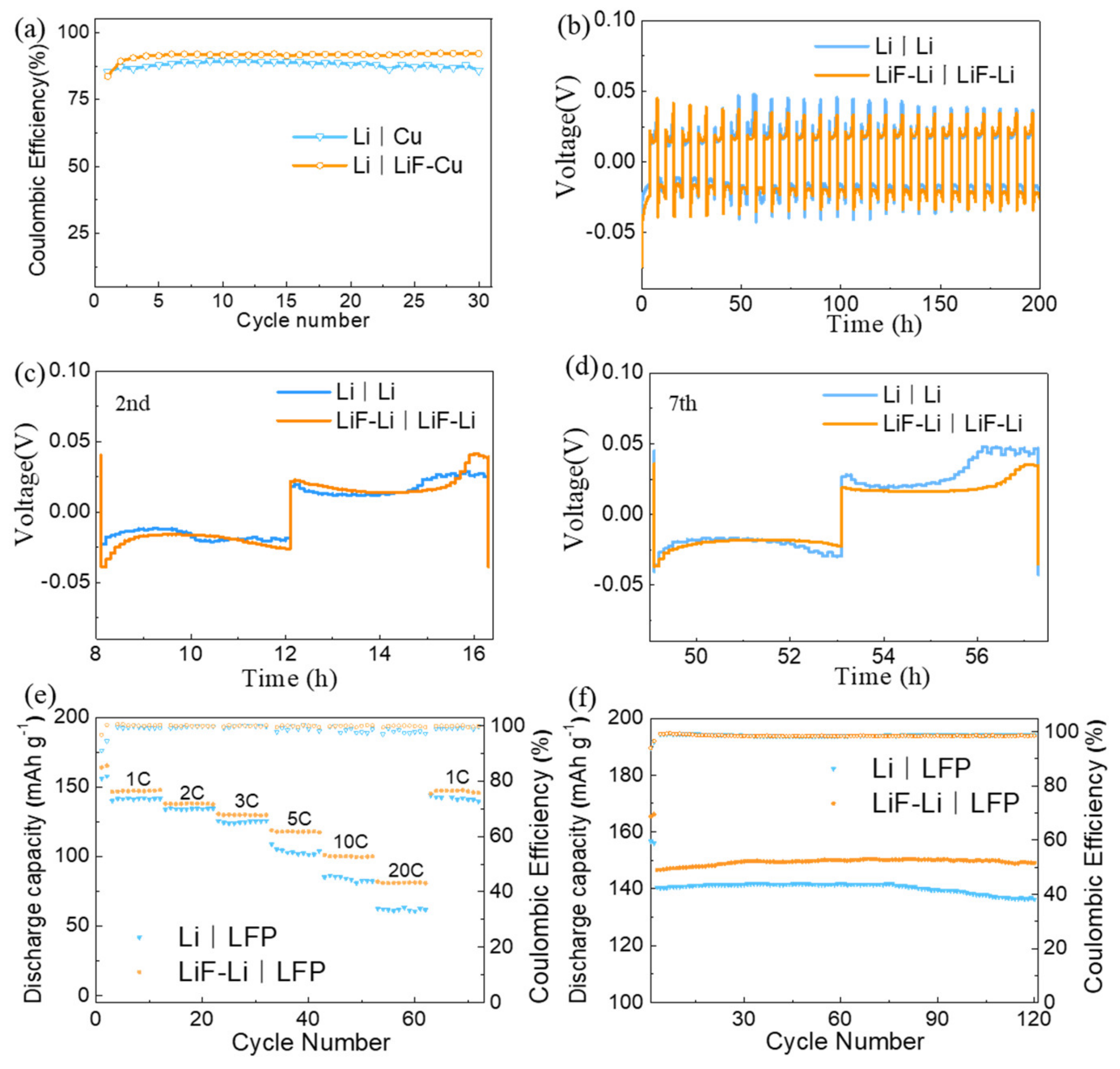
Using the Li-Cu half-cell is a common method to evaluate the coulomb efficiency of LMA. The LiF layer was formed on the surface of single-sided laminated lithium (50 μm) copper foil (Li-Cu) treated with PVDF at 400 °C (LiF-Li-Cu). First, all the Li of the LiF-Li-Cu was stripped to the counter lithium electrode and turned into a Li|LiF-Cu configuration. For comparison, a pristine Cu disc was paired with a Li counter electrode to assemble into a Li|Cu cell. The coulomb efficiency was tested by charging and discharging at the current density of 2 mAh cm−2. As shown in Figure 4a, Li|Cu shows an inferior stability and lowers the coulomb efficiency (CE) in the carbon electrolyte. After the charge and discharge of 22 cycles, the CE curve began to destabilize and decreased to 86% after 30 cycles. In contrast, the Li|LiF-Cu exhibits a more stable cycling performance. It can cycle beyond 30 cycles with a higher CE of 92%. This may be due to the advantages of the low surface diffusion resistance of the LiF coating layer, which is conducive in guiding the rapid deposition of Li+ and ensuring the optimization of the Li plating process. The current density of 3 mA/cm2 was used to remove all the Li from the LiF-Cu electrode, and then the lithium plating was conducted for 1 h. The LiF coating layer becomes cracked, as shown in Figure S2. Two kinds of structures are revealed: the upper layer is the LiF layer, and the lower layer is the plated lithium. In other words, the plated lithium preferentially grows under the LiF layer, near the side of Cu [35].
To further investigate the effect of LiF coating on electrochemical performance, a symmetrical lithium battery was also utilized. Figure 4b shows the cycle performance of the symmetrical batteries Li|Li and LiF-Li|LiF-Li with a pristine lithium chip and LiF-coated chips as electrodes, using the voltage response over time to monitor changes in battery stability. Figure 4c shows the voltage profile of the second cycle. Compared with the Li|Li, the LiF-Li|LiF-Li cell exhibits a smoother voltage curve. Significantly, the voltage profile becomes even bumpier with increasing cycles. As demonstrated by the voltage profile for the seventh cycle in Figure 4d, the Li|Li cell exhibits a higher overpotential than the LiF-Li|LiF-Li cell. This increase in overpotential may be caused by the continuous accumulation and decomposition of SEI at the electrolyte/electrode interface [36]. Once the lithium dendrites form, the initial SEI is pricked and quickly reacts with the electrolyte to form a new SEI, a process that can last for hundreds of hours, continuing to consume the electrolyte and form a thicker SEI. The LiF-coating layer on the surface of lithium metal not only has a high Li+ transmission capacity, but also can avoid the rapid chemical side- reaction due to the direct contact between the lithium and the electrolyte. This layer of artificial, prefabricated SEI can promote the uniform deposition of lithium and reduce the formation of lithium dendrites during charging and discharging. Therefore, the LiF-Li|LiF-Li cell has a lower overpotential and better cycle stability [35].
To explore the potential application, the LiF-coated LMA was paired with an LFP cathode to improve the energy density of a graphite/LFP battery. In Figure S3a,b, a group of redox peaks is visible at positions 3.3 V and 3.6 V. Notably, all the anodic and cathodic peaks in the LiF-Li|LFP cell CV curves are highly congruent in the subsequent cycles. This observation confirms the good reversibility of the tested LiF-Li|LFP cell. In Figure S4, electrochemical impedance spectra (EIS) measurements with symmetrical batteries were performed to evaluate the interfacial resistance of the lithium anode. The semicircle in the high-frequency region reflects the interfacial charge transfer process (Rct). The Rct formed by LiF-Li|LiF-Li after the first cycle is 64.56 Ω, less than the Rct (77.62 Ω) of Li|Li, possibly because the LiF layer plays positive roles in protecting the lithium anode interface during the stripping/plating process [46,47,48].
Figure 4e shows the rate-performance testing at different rates ranging from 1 C to 20 C (1 C = 170 mAh/g). The LiF-Li|LFP cells deliver the specific capacity, which is 148 mA h/g, 138 mA h/g, 130 mA h/g, 117 mA h/g, 100 mA h/g and 81 mA h/g at 1 C, 2 C, 3 C, 5 C, 10 C and 20 C, respectively. When the rate returns to 1 C, the specific capacity can be restored to 147 mA h/g. Compared with Li|LFP cells, LiF-Li|LFP cells have a higher specific capacity and better stability under different rates. Such advantages become more apparent with the increase of the testing rate. These results indicate that the prefabricated LiF layer on the surface of lithium can effectively stabilize the interface between the electrolytes and lithium and improve the cycle reversibility and rate performance of lithium metal batteries [49]. As shown in Figure 4f, the long-cycle performance of Li|LFP and LiF-Li|LFP cells was further evaluated at 1 C. Consistent with the results of rate performance, LF-Li|LFP cells exhibit a higher specific capacity than Li|LFP cells. The capacities of Li|LFP and F-Li|LFP decrease to 136 mA h/g and 149 mA h/g after 120 cycles, which correspond to capacity retention rates of 96% and 99%, respectively. The CE of LiF-Li|LFP cells is also slightly higher than that of Li|LFP cells. All these results further prove that an LiF-coating can effectively maintain the electrochemical reversibility and the cycle stability of lithium metal batteries.
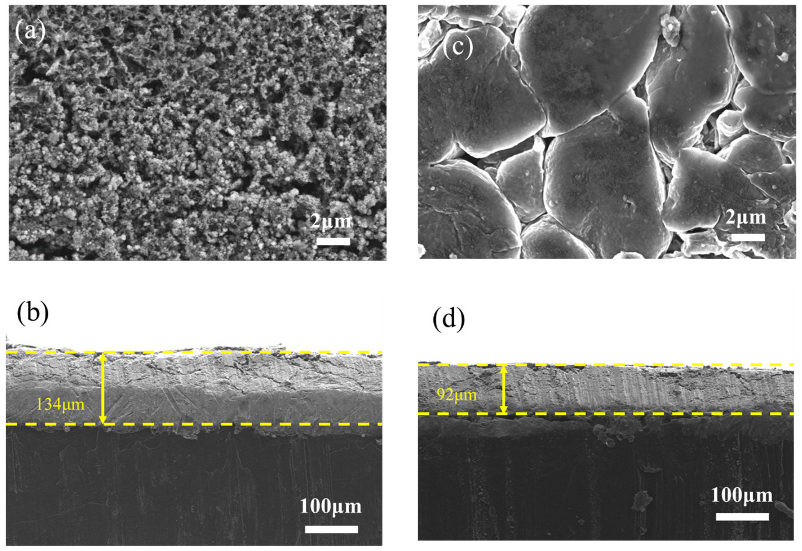
A postmortem analysis was further employed to investigate the morphology and SEI composition of lithium electrodes after cycles. Figure 5 shows the surface and cross-section SEM images of lithium electrodes of Li|LFP and LiF-Li|LFP at 1 C after 100 cycles. The surface of the lithium electrode from a Li|LFP cell (Figure 5a) is highly porous with a dendritic microstructure along with particles. In contrast, the lithium surface of the F-Li|LFP cell (Figure 5b) exhibits a smooth fish-scale structure, demonstrating that the growth of dendrites is suppressed by the LiF coating. Such results further confirm that the high Li+ lateral mobility on the surface of the LiF coating can favor the uniform lithium deposition and stripping and effectively suppress the dendrite formation during the cell charge/discharge process [35]. The cracks among the scales may be caused by the stress during the charge/discharge process. As shown by the cross-sectional SEM image of the lithium electrode from a Li|LFP cell in Figure 5c, the cycled penetration thickness reaches up to 134 μm, which is much thicker than that of the LiF-coated lithium electrode (~92 μm depth), as shown by the LiF-Li|LFP cell in Figure 5d.
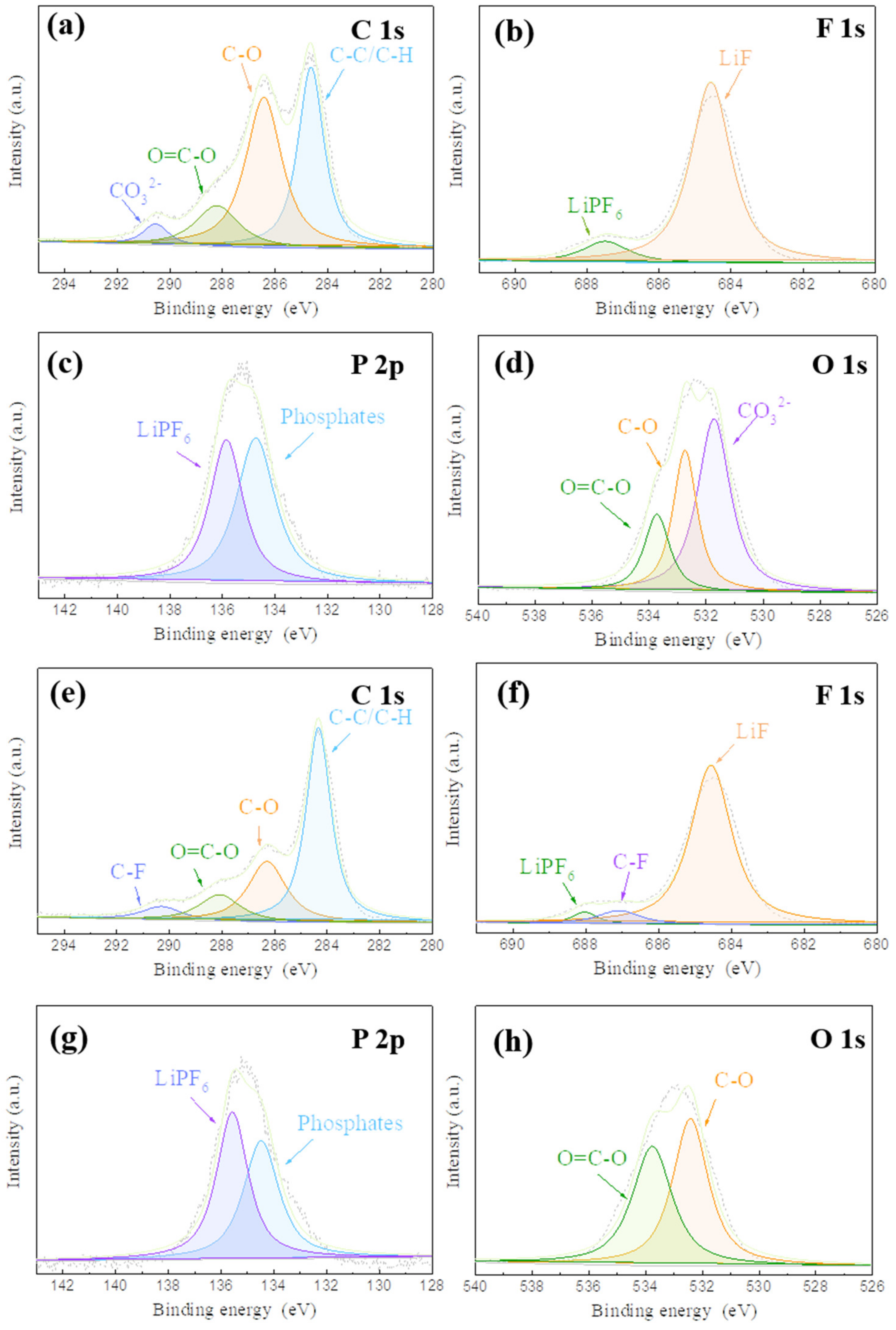
As shown in Figure 6a, the C1’s spectrum of the lithium metal from the Li|LFP cell after 100 cycles is deconvoluted into four peaks at 284.6, 286.3, 288.3 and 290.5eV corresponding to C-C/C-H, C-O, O=C-O and CO32−, respectively [34]. These peaks are consistent with the reactions of the products of decomposition of carbonate-based electrolytes [50]. The characteristic peak of C-F appears in the C1S spectrum of a LiF-coated Li surface (Figure 6e). The F1’s XPS spectra are shown in Figure 6b,f. The peaks at 685 and 688 eV are ascribed to the LiF and LiPF6, respectively. More LiF was observed for the LiF-coated lithium electrode than for the LIF-Li|LFP cell. The ratio of LiF to Li PF6(SLiF/LiPF6) is estimated by their integral area. The SLiF/LiPF6 is improved from 2.09 for the uncoated sample to 2.25 for the LiF-coated sample, indicating that the composition of the coating is maintained during charge/discharge cycles. Figure 6c,g show P 2p spectra, where LiPF6 and phosphates are detected. Compared with the uncoated lithium surface, the ratio of phosphate /LiPF6 on the F-Li surface is lower. C-O, O=C-O and CO32− shown in the O1’s spectrum in Figure 6d are consistent with those shown in C1’s orbital spectra [51]. Figure 6h shows that the LiF-Li surface has fewer by-products. In Figure S5 and Table S1, the content of the F element was higher on the lithium metal anode surface after 100 cycles at 1 C from the LiF-Li|LFP cell. This indicates that a LiF coating can effectively guide the nucleation and growth of lithium, inhibit the formation of dead lithium, and reduce the occurrence of side reactions, thus improving the electrochemical performance of the battery [52].

4. Conclusions

In summary, we have developed a simple CVD method for the prefabrication of a fluorinated interface on the surface of lithium metal. The HF produced by the decomposition of the PVDF reacts with the surface of lithium to form a uniform and stable LiF layer. This not only reduces the side reaction between lithium metal and the electrolyte but also effectively inhibits the growth of lithium dendrites. Therefore, as compared with a pristine lithium metal anode, this artificially prefabricated SEI can enhance the cycle stability of lithium metal batteries and their CE and capacity retention. rate. These results indicate that the prefabricated fluorinated interface has great potential in the application of lithium metal batteries.

Supplementary Materials

The following supporting information can be downloaded at: https://www.mdpi.com/article/10.3390/batteries9050283/s1: Figure S1: The XRD pattern of LiF-coated Li metal; Figure S2: The (a)SEM image and (b-e) EDS mapping images of LiF-Cu electrode; Figure S3: The CV curves of (a) Li | LFP cells, (b) LiF-Li | LFP cells during the first six charge-discharge cycles; Figure S4: Electrochemical impedance spectra (EIS) of Li|Li cells after the 1st cycle; Figure S5: The XPS survey spectra of lithium metal anode surface after 100 cycles at 1C from (a) Li | LFP cell and (b) LiF-Li | LFP cell; Table S1: Table S1. Atomic percent of lithium metal anode surface after 100 cycles at 1C from Li | LFP cell and LiF-Li | LFP cell.

Author Contributions

Investigation, Y.L., Y.H. and Y.Z.; Supervision, C.Z.; Writing–original draft, J.N.; Writing–review and editing, Z.G. and Q.X. All authors have read and agreed to the published version of the manuscript.

Funding

This work was supported by the National Natural Science Foundation of China (Grants 52073215), for which the authors are thankful.

Data Availability Statement

The data generated during the current study are available from the corresponding author on reasonable request.

Conflicts of Interest

We declare that we do not have any commercial or associative interest that represents a conflict of interest in connection with the work submitted.

References

  1. Liu, B.; Zhang, J.-G.; Xu, W. Advancing Lithium Metal Batteries. Joule 2018, 2, 833–845. [Google Scholar] [CrossRef]
  2. Ghazi, Z.A.; Sun, Z.; Sun, C.; Qi, F.; An, B.; Li, F.; Cheng, H. Key Aspects of Lithium Metal Anodes for Lithium Metal Batteries. Small 2019, 15, e1900687. [Google Scholar] [CrossRef]
  3. Xu, W.; Wang, J.; Ding, F.; Chen, X.; Nasybulin, E.; Zhang, Y.; Zhang, J.-G. Lithium metal anodes for rechargeable batteries. Energy Environ. Sci. 2014, 7, 513–537. [Google Scholar] [CrossRef]
  4. Lu, Y.; Tu, Z.; Archer, L.A. Stable lithium electrodeposition in liquid and nanoporous solid electrolytes. Nat. Mater. 2014, 13, 961–969. [Google Scholar] [CrossRef]
  5. Yan, C.; Cheng, X.; Tian, Y.; Chen, X.; Zhang, X.; Li, W.; Huang, J.; Zhang, Q. Dual-Layered Film Protected Lithium Metal Anode to Enable Dendrite-Free Lithium Deposition. Adv. Mater. 2018, 30, e1707629. [Google Scholar] [CrossRef]
  6. Zhang, R.; Chen, X.R.; Chen, X.; Cheng, X.B.; Zhang, X.Q.; Yan, C.; Zhang, Q. Lithiophilic Sites in Doped Graphene Guide Uniform Lithium Nucleation for Dendrite-Free Lithium Metal Anodes. Angew. Chem. Int. Ed. Engl. 2017, 56, 7764–7768. [Google Scholar] [CrossRef]
  7. Aurbach, D. Review of selected electrode-solution interactions which determine the performance of Li and Li ion batteries. J. Power Sources 2000, 89, 206–218. [Google Scholar] [CrossRef]
  8. Harry, K.J.; Hallinan, D.; Parkinson, D.Y.; MacDowell, A.A.; Balsara, N.P. Detection of subsurface structures underneath dendrites formed on cycled lithium metal electrodes. Nat. Mater. 2014, 13, 69–73. [Google Scholar] [CrossRef]
  9. Wood, K.N.; Kazyak, E.; Chadwick, A.F.; Chen, K.-H.; Zhang, J.-G.; Thornton, K.; Dasgupta, N.P. Dendrites and Pits: Untangling the Complex Behavior of Lithium Metal Anodes through Operando Video Microscopy. ACS Cent. Sci. 2016, 2, 790–801. [Google Scholar] [CrossRef]
  10. Liu, F.; Xiao, Q.; Bin Wu, H.; Shen, L.; Xu, D.; Cai, M.; Lu, Y. Fabrication of Hybrid Silicate Coatings by a Simple Vapor Deposition Method for Lithium Metal Anodes. Adv. Energy Mater. 2018, 8, 1701744. [Google Scholar] [CrossRef]
  11. Xu, R.; Xiao, Y.; Zhang, R.; Cheng, X.; Zhao, C.; Zhang, X.; Yan, C.; Zhang, Q.; Huang, J. Dual-Phase Single-Ion Pathway Interfaces for Robust Lithium Metal in Working Batteries. Adv. Mater. 2019, 31, e1808392. [Google Scholar] [CrossRef]
  12. Calderón, C.A.; Vizintin, A.; Bobnar, J.; Barraco, D.E.; Leiva, E.P.; Visintin, A.; Fantini, S.; Fischer, F.; Dominko, R. Lithium Metal Protection by a Cross-Linked Polymer Ionic Liquid and Its Application in Lithium Battery. ACS Appl. Energy Mater. 2020, 3, 2020–2027. [Google Scholar] [CrossRef]
  13. Chen, L.; Connell, J.G.; Nie, A.; Huang, Z.; Zavadil, K.R.; Klavetter, K.C.; Yuan, Y.; Sharifi-Asl, S.; Shahbazian-Yassar, R.; Libera, J.A.; et al. Lithium metal protected by atomic layer deposition metal oxide for high performance anodes. J. Mater. Chem. A 2017, 5, 12297–12309. [Google Scholar] [CrossRef]
  14. Alaboina, P.K.; Rodrigues, S.; Rottmayer, M.; Cho, S.-J. In Situ Dendrite Suppression Study of Nanolayer Encapsulated Li Metal Enabled by Zirconia Atomic Layer Deposition. ACS Appl. Mater. Interfaces 2018, 10, 32801–32808. [Google Scholar] [CrossRef]
  15. Jie, Y.; Ren, X.; Cao, R.; Cai, W.; Jiao, S. Advanced Liquid Electrolytes for Rechargeable Li Metal Batteries. Adv. Funct. Mater. 2020, 30, 1910777. [Google Scholar] [CrossRef]
  16. Borodin, O. Challenges with prediction of battery electrolyte electrochemical stability window and guiding the electrode—Electrolyte stabilization. Curr. Opin. Electrochem. 2019, 13, 86–93. [Google Scholar] [CrossRef]
  17. Zheng, Q.; Yamada, Y.; Shang, R.; Ko, S.; Lee, Y.-Y.; Kim, K.; Nakamura, E.; Yamada, A. A cyclic phosphate-based battery electrolyte for high voltage and safe operation. Nat. Energy 2020, 5, 291–298. [Google Scholar] [CrossRef]
  18. Ni, J.; Jin, L.; Xue, M.; Xiao, Q.; Zheng, J.; Zheng, J.P.; Zhang, C. TiO2 microbox/carbon nanotube composite-modified separator for high-performance lithium-sulfur batteries. J. Solid. State Electrochem. 2020, 25, 949–961. [Google Scholar] [CrossRef]
  19. Ji, M.; Ni, J.; Liang, X.; Cheng, Q.; Gao, G.; Wu, G.; Xiao, Q. Biomimetic Synthesis of VO x @C Yolk-Shell Nanospheres and Their Application in Li—S Batteries. Adv. Funct. Mater. 2022, 32, 2206589. [Google Scholar] [CrossRef]
  20. Jeong, H.-S.; Lee, S.-Y. Closely packed SiO2 nanoparticles/poly(vinylidene fluoride-hexafluoropropylene) layers-coated polyethylene separators for lithium-ion batteries. J. Power Sources 2011, 196, 6716–6722. [Google Scholar] [CrossRef]
  21. Song, Y.H.; Wu, K.J.; Zhang, T.W.; Lu, L.-L.; Guan, Y.; Zhou, F.; Wang, X.-X.; Yin, Y.-C.; Tan, Y.-H.; Li, F.; et al. A Nacre-Inspired Separator Coating for Impact-Tolerant Lithium Batteries. Adv. Mater. 2019, 31, e1905711. [Google Scholar] [CrossRef]
  22. Zhang, X.; Yang, Y.; Zhou, Z. Towards practical lithium-metal anodes. Chem. Soc. Rev. 2020, 49, 3040–3071. [Google Scholar] [CrossRef]
  23. Jiang, G.; Li, K.; Yu, F.; Li, X.; Mao, J.; Jiang, W.; Sun, F.; Dai, B.; Li, Y. Robust Artificial Solid-Electrolyte Interfaces with Biomimetic Ionic Channels for Dendrite-Free Li Metal Anodes. Adv. Energy Mater. 2020, 11, 2003496. [Google Scholar] [CrossRef]
  24. Zhu, B.; Jin, Y.; Hu, X.; Zheng, Q.; Zhang, S.; Wang, Q.; Zhu, J. Poly(dimethylsiloxane) Thin Film as a Stable Interfacial Layer for High-Performance Lithium-Metal Battery Anodes. Adv. Mater. 2017, 29, 1701568. [Google Scholar] [CrossRef]
  25. Zhai, P.; Liu, L.; Gu, X.; Wang, T.; Gong, Y. Interface Engineering for Lithium Metal Anodes in Liquid Electrolyte. Adv. Energy Mater. 2020, 10, 2001257. [Google Scholar] [CrossRef]
  26. Ozhabes, Y.; Gunceler, D.; Arias, T.A. Stability and surface diffusion at lithium-electrolyte interphases with connections to dendrite suppression. arXiv 2015, preprint. arXiv:1504.05799. [Google Scholar]
  27. Lin, D.; Liu, Y.; Chen, W.; Zhou, G.; Liu, K.; Dunn, B.; Cui, Y. Conformal Lithium Fluoride Protection Layer on Three-Dimensional Lithium by Nonhazardous Gaseous Reagent Freon. Nano Lett. 2017, 17, 3731–3737. [Google Scholar] [CrossRef]
  28. Yu, T.; Zhao, T.; Zhang, N.; Xue, T.; Chen, Y.; Ye, Y.; Wu, F.; Chen, R. Spatially Confined LiF Nanoparticles in an Aligned Polymer Matrix as the Artificial SEI Layer for Lithium Metal Anodes. Nano Lett. 2023, 23, 276–282. [Google Scholar] [CrossRef]
  29. Zhang, H.; Zeng, Z.; Ma, F.; Wang, X.; Wu, Y.; Liu, M.; He, R.; Cheng, S.; Xie, J. Juggling Formation of HF and LiF to Reduce Crossover Effects in Carbonate Electrolyte with Fluorinated Cosolvents for High-Voltage Lithium Metal Batteries. Adv. Funct. Mater. 2022, 33, 2212000. [Google Scholar] [CrossRef]
  30. Choudhury, S.; Archer, L.A. Lithium Fluoride Additives for Stable Cycling of Lithium Batteries at High Current Densities. Adv. Electron. Mater. 2016, 2, 1500246. [Google Scholar] [CrossRef]
  31. Shadike, Z.; Lee, H.; Borodin, O.; Cao, X.; Fan, X.; Wang, X.; Lin, R.; Bak, S.-M.; Ghose, S.; Xu, K.; et al. Identification of LiH and nanocrystalline LiF in the solid-electrolyte interphase of lithium metal anodes. Nat. Nanotechnol. 2021, 16, 549–554. [Google Scholar] [CrossRef] [PubMed]
  32. Jurng, S.; Brown, Z.L.; Kim, J.; Lucht, B.L. Effect of electrolyte on the nanostructure of the solid electrolyte interphase (SEI) and performance of lithium metal anodes. Energy Environ. Sci. 2018, 11, 2600–2608. [Google Scholar] [CrossRef]
  33. Liu, Z.; He, B.; Zhang, Z.; Deng, W.; Dong, D.; Xia, S.; Zhou, X.; Liu, Z. Lithium/Graphene Composite Anode with 3D Structural LiF Protection Layer for High-Performance Lithium Metal Batteries. ACS Appl. Mater. Interfaces 2022, 14, 2871–2880. [Google Scholar] [CrossRef] [PubMed]
  34. Kim, H.; Kim, Y.S.; Yoo, J. An in situ formed LiF protective layer on a Li metal anode with solvent-less cross-linking. Sustain. Energy Fuels 2020, 4, 3282–3287. [Google Scholar] [CrossRef]
  35. Yuan, Y.; Wu, F.; Bai, Y.; Li, Y.; Chen, G.; Wang, Z.; Wu, C. Regulating Li deposition by constructing LiF-rich host for dendrite-free lithium metal anode. Energy Storage Mater. 2019, 16, 411–418. [Google Scholar] [CrossRef]
  36. Lang, J.; Long, Y.; Qu, J.; Luo, X.; Wei, H.; Huang, K.; Zhang, H.; Qi, L.; Zhang, Q.; Li, Z.; et al. One-pot solution coating of high quality LiF layer to stabilize Li metal anode. Energy Storage Mater. 2019, 16, 85–90. [Google Scholar] [CrossRef]
  37. Zhao, J.; Liao, L.; Shi, F.; Lei, T.; Chen, G.; Pei, A.; Sun, J.; Yan, K.; Zhou, G.; Xie, J.; et al. Surface Fluorination of Reactive Battery Anode Materials for Enhanced Stability. J. Am. Chem. Soc. 2017, 139, 11550–11558. [Google Scholar] [CrossRef]
  38. Xie, J.; Liao, L.; Gong, Y.; Li, Y.; Shi, F.; Pei, A.; Sun, J.; Zhang, R.; Kong, B.; Subbaraman, R.; et al. Stitching h-BN by atomic layer deposition of LiF as a stable interface for lithium metal anode. Sci. Adv. 2017, 3, eaao3170. [Google Scholar] [CrossRef]
  39. Chen, L.; Chen, K.-S.; Chen, X.; Ramierez, G.; Huang, Z.; Geise, N.R.; Steinrück, H.-G.; Fisher, B.L.; Shahbazian-Yassar, R.; Toney, M.F.; et al. Novel ALD Chemistry Enabled Low-Temperature Synthesis of Lithium Fluoride Coatings for Durable Lithium Anodes. ACS Appl. Mater. Interfaces 2018, 10, 26972–26981. [Google Scholar] [CrossRef]
  40. Ko, J.; Yoon, Y.S. Lithium fluoride layer formed by thermal evaporation for stable lithium metal anode in rechargeable batteries. Thin Solid. Film. 2019, 673, 119–125. [Google Scholar] [CrossRef]
  41. Fan, L.; Zhuang, H.L.; Gao, L.; Lu, Y.; Archer, L.A. Regulating Li deposition at artificial solid electrolyte interphases. J. Mater. Chem. A 2017, 5, 3483–3492. [Google Scholar] [CrossRef]
  42. Vernardou, D. Special Issue: Advances in Chemical Vapor Deposition. Materials 2020, 13, 4167. [Google Scholar] [CrossRef] [PubMed]
  43. Zuo, X.; Ma, X.; Wu, J.; Deng, X.; Xiao, X.; Liu, J.; Nan, J. Self-supporting ethyl cellulose/poly(vinylidene fluoride) blended gel polymer electrolyte for 5 V high-voltage lithium-ion batteries. Electrochim. Acta 2018, 271, 582–590. [Google Scholar] [CrossRef]
  44. Tian, X.; Xin, B.; Gao, W.; Jin, S.; Chen, Z. Preparation and characterization of polyvinylidene fluoride/polysulfone-amide composite nanofiber mats. J. Text. Inst. 2018, 110, 815–821. [Google Scholar] [CrossRef]
  45. Singha, S.; Jana, T. Effect of composition on the properties of PEM based on polybenzimidazole and poly(vinylidene fluoride) blends. Polymer 2014, 55, 594–601. [Google Scholar] [CrossRef]
  46. Sanad, M.M.S.; Meselhy, N.K.; El-Boraey, H.A.; Toghan, A. Controllable engineering of new ZnAl2O4-decorated LiNi0·8Mn0·1Co0·1O2 cathode materials for high performance lithium-ion batteries. J. Mater. Res. Technol. 2023, 23, 1528–1542. [Google Scholar] [CrossRef]
  47. Moustafa, M.G.; Sanad, M.M.S. Green fabrication of ZnAl2O4-coated LiFePO4 nanoparticles for enhanced electrochemical performance in Li-ion batteries. J. Alloy. Compd. 2022, 903, 163910. [Google Scholar] [CrossRef]
  48. Heine, J.; Krüger, S.; Hartnig, C.; Wietelmann, U.; Winter, M.; Bieker, P. Coated Lithium Powder (CLiP) Electrodes for Lithium-Metal Batteries. Adv. Energy Mater. 2014, 4, 1300815. [Google Scholar] [CrossRef]
  49. Li, C.; Li, Y.; Yu, Y.; Shen, C.; Zhou, C.; Dong, C.; Zhao, T.; Xu, X. One-Pot Preparation of Lithium Compensation Layer, Lithiophilic Layer, and Artificial Solid Electrolyte Interphase for Lean-Lithium Metal Anode. ACS Appl. Mater. Interfaces 2022, 14, 19437–19447. [Google Scholar] [CrossRef]
  50. Zheng, J.; Yan, P.; Cao, R.; Xiang, H.; Engelhard, M.H.; Polzin, B.J.; Wang, C.; Zhang, J.-G.; Xu, W. Effects of Propylene Carbonate Content in CsPF(6)-Containing Electrolytes on the Enhanced Performances of Graphite Electrode for Lithium-Ion Batteries. ACS Appl. Mater. Interfaces 2016, 8, 5715–5722. [Google Scholar] [CrossRef]
  51. Li, X.; Zheng, Y.; Pan, Q.; Li, C.Y. Polymerized Ionic Liquid-Containing Interpenetrating Network Solid Polymer Electrolytes for All-Solid-State Lithium Metal Batteries. ACS Appl. Mater. Interfaces 2019, 11, 34904–34912. [Google Scholar] [CrossRef] [PubMed]
  52. Zhou, S.; Zhang, Y.; Chai, S.; Usman, I.; Qiao, Y.; Luo, S.; Xie, X.; Chen, J.; Liang, S.; Pan, A.; et al. Incorporation of LiF into functionalized polymer fiber networks enabling high capacity and high rate cycling of lithium metal composite anodes. Chem. Eng. J. 2021, 404, 126508. [Google Scholar] [CrossRef]
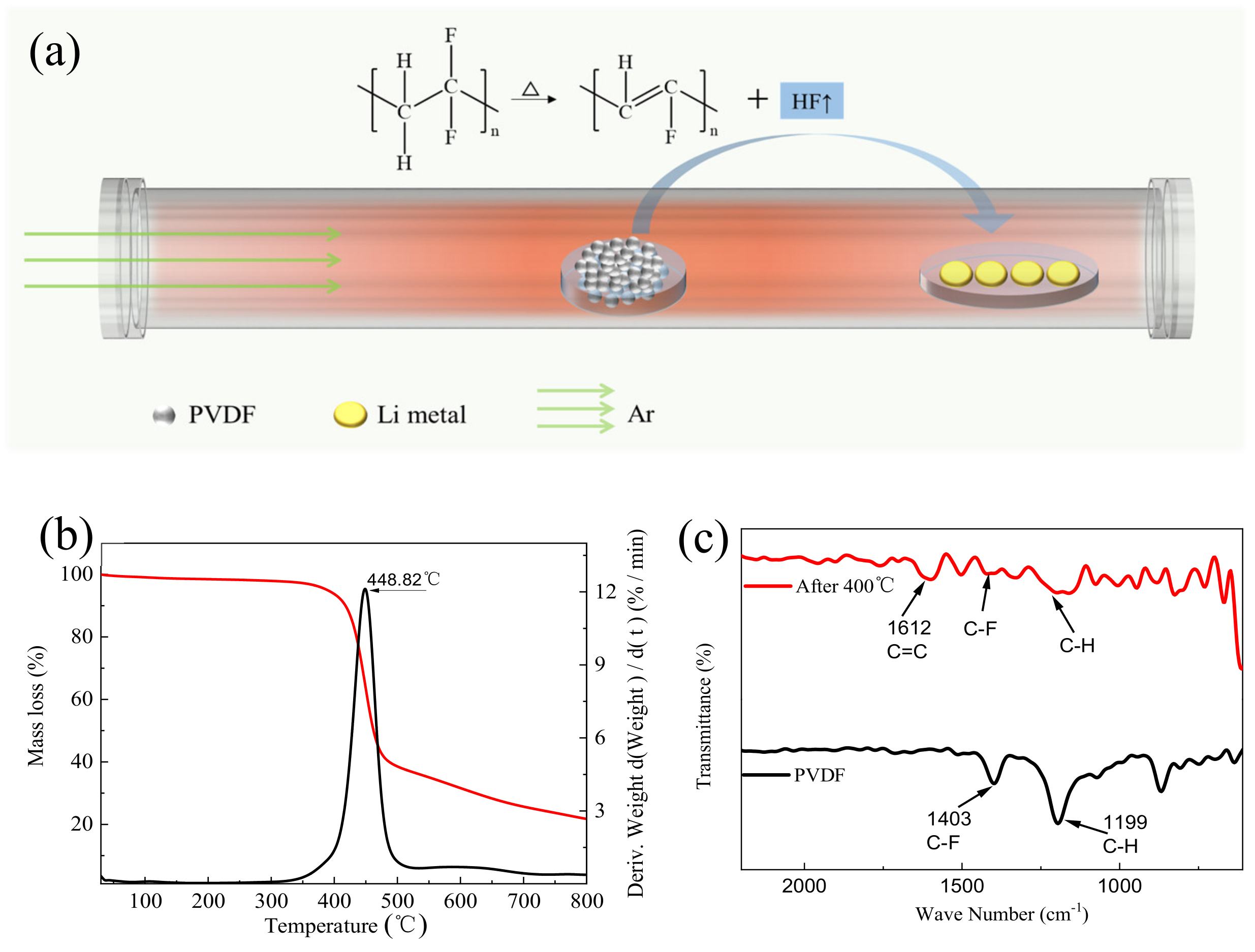
Figure 1. (a) Schematic illustration of a one-pot process to prefabricate a LiF-coating on the surface of lithium chips by CVD. (b) TGA and DTG curves of PVDF at a heating rate of 10 °C min−1 under Ar. (c) FTIR spectra of pristine PVDF and PVDF residue heated at 400 °C for 30 min under Ar.
Batteries 09 00283 g001
Figure 2. Digital images of (a) pristine lithium and (b) LiF-coated lithium. Top view: SEM images of (c) pristine lithium and (d) LiF-coated lithium. (e) Cross-sectional SEM image of fluorinated lithium. (f) EDS spectra of LiF-coated lithium.
Batteries 09 00283 g002
Figure 3. XPS spectra of Li 1s for (a) pristine lithium and (b) LiF-coated lithium. XPS spectra of (c) C 1s and (d) F 1s for LiF-coated lithium.
Batteries 09 00283 g003
Figure 4. (a) Coulombic efficiency of Li|Cu and Li|LiF-Cu cells. (b) Voltage profiles obtained from galvanostatic cycling of symmetrical cells using pristine Li electrodes and LiF-Li electrodes at a current density of 0.5 mA cm−2 for a total capacity of 2 mA h cm−2. Zoomed-in view of the voltage profiles of Li|Li and LiF-Li|LiF-Li at the (c) 2nd cycle and at the (d) 7th cycle. (e) Rate performance: (f) the long cycling performance at 1 C of Li|LFP and LiF-Li|LFP cells.
Batteries 09 00283 g004
Figure 5. SEM images of (a) the surface and (b) cross-section of a lithium electrode from Li|LFP cells after 100 cycles at 1 C. SEM images of (c) the surface and (d) cross-section of a LiF-coated lithium electrode from LiF-Li|LFP cells after 100 cycles at 1 C.
Batteries 09 00283 g005
Figure 6. (ad) XPS spectra of a pristine lithium anode after 100 cycles at 1 C from a Li|LFP cell. (eh) XPS spectra of a lithium anode after 100 cycles at 1C from a LiF-Li|LFP cell.
Batteries 09 00283 g006
Disclaimer/Publisher’s Note: The statements, opinions and data contained in all publications are solely those of the individual author(s) and contributor(s) and not of MDPI and/or the editor(s). MDPI and/or the editor(s) disclaim responsibility for any injury to people or property resulting from any ideas, methods, instructions or products referred to in the content.