Article

Analysis of Essential Features and Optimal Operational Parameters of an RF-ICP Torch for Waste Treatment Applications

1
Faculty of Engineering and Applied Science, Ontario Tech University, 2000 Simcoe St. North, Oshawa, ON L1G 0C5, Canada
2
National Research Institute of Astronomy and Geophysics (NRIAG), Cairo 11421, Egypt
*
Author to whom correspondence should be addressed.
Recycling 2024, 9(1), 20; https://doi.org/10.3390/recycling9010020
Submission received: 25 December 2023 / Revised: 5 February 2024 / Accepted: 8 February 2024 / Published: 15 February 2024

Abstract

:
Recently, plasma-based pyrolysis has gained increasing prominence as a technology in response to the growing challenges in waste disposal and the recognition of opportunities to generate valuable by-products. The efficiency of the pyrolysis process is intricately tied to the characteristics of the plasma involved, particularly the effective electron temperature (Teff) and plasma density (ne). This study aimed to conduct a comprehensive examination of the essential features and optimal operational parameters of a developed RF-ICP torch specifically designed for small-scale municipal solid waste (MSW) pyrolysis (mixture of paper and polypropylene) with the goal of controlling both the torch and the overall process. Using optical emission spectroscopy (OES), we measured plasma parameters, specifically (Teff) and (ne), while varying argon gas flow rates and RF powers. The (Teff) and (ne)were determined using the Boltzmann plot and Stark broadening, respectively. The RF torch was found to generate (ne) up to approximately 2.8 × 10 20   cm 3 and (Teff) up to around 8200 K, with both parameters being controlled by the discharge power and gas flow rate. Additionally, a power-losing mechanism, namely the anomalous skin effect, was detected during the study, which is uncommon in atmospheric plasma discharge.

1. Introduction

Municipal solid waste (MSW) represents the waste generated daily by people, known for its widespread occurrence and intricate composition. The significant increase in waste production can be attributed to the processes of urbanization and industrialization. The practice of mass burn incineration has traditionally been a prominent thermal method for managing MSW [1,2]. There are more than 1400 operational incineration facilities globally, and many more are in the process of being commissioned for waste-to-energy applications [3]. However, the overall energy efficiency of contemporary incineration plants remains relatively low, typically falling within the range of 22% to 25%; this is primarily due to the necessity of maintaining lower steam temperatures, usually around 450 °C, to safeguard equipment from corrosion induced by acidic gases such as HCl [4]. Consequently, the demand for excessive airflow constrains the achievable temperature within the incineration process chamber, leading to the production of hazardous pollutants, including chlorinated dioxins and furans. These contaminants contribute to air pollution and are linked to severe health concerns such as cancer and developmental abnormalities [5]. Despite the incorporation of state-of-the-art technologies for environmentally friendly waste disposal in modern incineration plants, the potential for generating toxic gases remains a subject of debate [6]. The highest likelihood of dioxin formation occurs within the temperature range of 350 to 400 °C [7]. To address the negative environmental impacts associated with incineration, alternative technologies such as pyrolysis and gasification have emerged as practical options. These methods have demonstrated their ability to reduce the generation of dioxins and furans to acceptable levels [8]. Among these alternatives, gasification is considered more efficient for large-scale waste disposal. However, it does produce unwanted byproducts, such as tar, in addition to desired outcomes such as syngas, producer gas, and char [9]. The presence of tar in the product gas can lead to various adverse effects, including diminished product quality, fouling of pipelines, corrosion, and deactivation of catalysts [10]. In this context, thermal plasma technology stands out as the singular thermal waste treatment process capable of effectively managing diverse waste types, including hazardous materials, while converting waste into valuable products without harming the environment [11]. It offers a range of advantages over conventional methods, which encompass exceptional destruction efficiency (with volume reduction surpassing 99%), the removal of harmful molecules, decreased CO2 emissions, and the production of high-calorific-value gas [12,13]. By its high-temperature heat source and the presence of charged particles, plasma fosters increased reactivity within the environment. This, in turn, promotes the decomposition of tar and augments the rate at which tar is eliminated [14,15]. The adoption of thermal plasma technology has been on the rise and is being implemented in countries such as the UK, USA, Canada, Belgium, and India, where it serves as a waste-to-energy solution for electricity generation, with capacities reaching up to 100 MW [16]. The realm of plasma-assisted waste processing technology is broadly categorized into two methods: plasma pyrolysis and plasma gasification. In plasma gasification, waste is subjected to a controlled quantity of oxygen, while plasma pyrolysis involves decomposing waste in an oxygen-deprived environment [5,12,17]. In the context of thermal treatment, an air supply of less than or equal to 5% relative to stoichiometric air can be considered to lead to pyrolysis conditions for waste treatment [18]. Numerous studies, ranging from laboratory- to pilot-scale, have been conducted to explore the environmental and output implications of employing plasma pyrolysis technology for waste management. A wide array of waste materials, including polyethylene, polypropylene, rubber, tires, biomass, paper, refuse-derived fuel, and medical waste, have been treated using different power sources, such as DC, AC, RF, and microwave, with power supply capacities ranging from 0.8 to 50 kW. In all instances, the primary composition of explosive products comprises H2 and CO. The concentration of pollutants like CO2 varies from 2% to 15%, while solid residues, taking the form of carbon black, slag, or ash, fall within the range of 6% to 40% [19,20]. Initially, it has been reported that the eco-friendly treatment of medical waste using plasma pyrolysis technology necessitates an energy consumption of approximately one kWh per kg [13]. Furthermore, Plasma Gasification Melting technology has been employed to convert MSW at a rate of 300 kg/h into syngas with energy content ranging from 6 to 7 MJ/Nm3. In this process, steam feed rates vary from 70 to 100 kg/h, and plasma power consumption ranges from 0.8 to 0.87 kWh/kg [21]. Stringent environmental regulations have created opportunities for plasma pyrolysis technology to emerge as a highly viable option for managing MSW and other solid wastes such as e-waste, ensuring minimal environmental impacts [22].
Thermal plasma refers to a high-temperature plasma operating at elevated pressures, typically close to atmospheric levels. It is characterized by high power and current densities within the plasma, resulting in significant enthalpy. This property allows thermal plasma to efficiently heat injected materials and electrodes. As a result of its exceptional heat capacity, thermal plasma finds widespread use in applications such as arc welding, plasma arc cutting, waste disposal, material deposition, and more [23,24]. In some cases, thermal plasma can be generated not only between electrodes but also through inductive coupling, giving rise to what is known as inductively coupled thermal plasma (ICTP) [25,26]. Reed originally developed the fundamental configuration of ICTP in the 1960s [27]. It involves the establishment of plasma within a cylindrical dielectric tube encircled by an induction coil. Radiofrequency (RF) current flowing through the coil generates electromagnetic fields, which, in turn, accelerate electrons within the torch, thus creating plasma. When operating at high pressures, typically near atmospheric levels, the plasma assumes a thermal state, with gas temperatures reaching several thousand Kelvins, closely aligned with electron temperatures. One of the most significant advantages of ICTP is its ability to generate a clean, high-temperature environment free from contamination by electrode materials. Capitalizing on these benefits, ICTPs have found diverse applications, including waste disposal [28], thermal barrier coating production [29,30,31], plasma spray–physical vapor deposition technique [32], diamond film deposition [33,34], fullerene synthesis [35,36], fine powder spheroidization [37,38,39], nanopowder synthesis [40,41,42,43], nanotube production [44,45], catalyst synthesis [46], and astrophysical research [47]. Despite the successful utilization of ICTP torches in numerous material processes, certain limitations have also emerged. These include challenges related to stable operation in the presence of disturbances, counterflows within the circulating gas, reduced power efficiency, and difficulties in controlling gas temperatures [48]. Therefore, examining plasma properties, such as plasma density and electron temperature, is essential for developing and improving the RF-ICP torches.
The electrical probe is usually used to assess the electron temperature and density of low-pressure plasmas [49,50,51,52]. Nevertheless, there is currently no established probe theory for atmospheric pressure plasmas characterized by a substantial electron-neutral collision frequency. Additionally, applying probe measurements to atmospheric pressure plasmas faces challenges related to significant heat load and high-frequency noise [53,54]. Consequently, optical methods that rely on spectral line emission intensity are frequently employed as an alternative to probe measurements for determining internal plasma parameters (Teff and ne) within the atmospheric pressure range plasma [55,56,57,58,59].
The electron temperature of rf inductive Ar plasmas at atmospheric pressure was determined by analyzing the line intensity ratio of the visible spectrum using the Boltzmann plot method. This approach assumes that the plasma is in a local thermodynamic equilibrium (LTE) condition [55,56,57,58,59]. Through spectroscopic analysis of the widening of spectral lines caused by the presence of electric fields in the plasma, Stark broadening is a technique used to detect the electron density in a plasma [60]. When the electric fields inside a plasma cause atoms or ions’ energy levels to change, this phenomenon is known as Stark broadening. The interactions between charged particles within the plasma give rise to the electric fields. Spectral lines expand because of this change in energy levels. The form of the line profile can be used to identify the widening of spectral lines caused by the Stark effect. The profile of sharply widened lines is more asymmetrical and wider than that of natural line shapes. The intensity of the electric field and, hence, the electron density in the plasma may be determined by researchers by examining the width and form of spectral lines in the plasma, especially those that correspond to transitions in atomic or ionic species [60]. Even though Stark broadening offers a useful technique for diagnosing plasma density, it’s important to consider variables such as pressure, temperature, and possible overlapping effects from other widening mechanisms (like Doppler broadening) [60,61]. A range of plasmas, including astrophysical and laboratory plasmas, can be subjected to Stark broadening. This approach is especially helpful in situations when applying conventional diagnostic methods, such as Langmuir probes, may be difficult, especially in high-temperature plasmas. Typically, hydrogen lines are employed for assessing Stark broadening, either by introducing hydrogen into the discharge for this purpose or by utilizing hydrogen as the plasma-forming gas [60,62]. In applications involving pyrolysis, inert gases such as Ar or N2 are commonly used as gas to form plasma [63]. To our knowledge, Stark broadening of RF-ICP torches at atmospheric pressure and frequency 13.56 MHz has not yet been calculated.
Our research team is working on the development of a small-scale MSW waste pyrolysis using a homemade atmospheric RF-ICP torch that works at a low power of 1.1 KW. The prior investigation conducted by our research team comprehensively explored the characteristics of the waste material comprising a mixture of paper and polypropylene [64]. This study was integral to the development of a small-scale plasma-based pyrolysis process designed specifically for such wastes. The present research sought to comprehensively analyze the essential features and optimal operational parameters of an RF-ICP torch specifically designed for this waste system by capturing and analyzing argon plasma spectra outside the plasma chamber. Furthermore, we evaluated the accuracy of measuring Stark broadening using Ar lines in the range of 700–850 nm.

2. Results

One of the key benefits of employing RF-ICP discharge in various applications is its capacity to produce high-density plasma [65]. Within the RF-ICP discharge, it is primarily the electrons that play a pivotal role in driving the excitation and ionization processes occurring in the discharge; this is because only electrons can swiftly navigate the rapidly changing electric field. In contrast, ions within the RF discharge are less influential and do not significantly contribute to the RF plasma discharge due to their limited mobility [66]. The high-frequency magnetic field in RF-ICP serves as the driving force for accelerating electrons, elevating their energy levels significantly. Among these energized electrons, those possessing energy exceeding 13 eV undergo collisions with ground-state argon atoms, thereby inducing a transition from their base state to an excited state. When these argon atoms exist in either the excited state Ar* or the higher excited state Ar**, their return to a metastable state or resonance energy level results in the emission of light. This sequence of events is mathematically represented by the following equations [55]:
e + Ar Ar * + e  
Ar * Ar + h ν  
e + Ar Ar * * + e  
Ar * * Ar + h ν  
OES analysis of the Ar RF-ICP discharge encompassed wavelengths ranging from 400 to 950 nm and different ranges of power (440, 550, 660, 770, 880, 990, and 1100 W) and argon gas flow rates (2 and 4 standard liters per minute (SLPM)). In Figure 1a,b, the emission spectrum of the atmospheric pressure Ar RF-ICP is depicted, observed under specific conditions involving an applied power of 440 watts and Ar gas flow rates of 2 and 4 SLPM, respectively. The spectral lines detected within the wavelength range of 696.53 to 852.14 nm primarily originated from excited atomic species denoted as Ar* (first excited state of Ar).
Within the Ar RF-ICP discharge, a total of eighteen atomic lines spanning from 696.53 to 852.14 nm were identified. Table 1 provides a compilation of the parameters associated with these atomic lines, sourced from NIST. The intensity of the line could show a direct correlation with the quantity of atoms in the excited state. Subsequent discussions delve into the patterns of intensity variation for these lines under various plasma conditions.
Ar* lines were examined under varying applied RF power levels of 440, 550, 660, 770, 880, 990, and 1100 W, with corresponding gas flow rates of 2 and 4 SLPM in Figure 2a,b. At 2 SLPM gas flow rate (refer to Figure 2a), it is evident that the intensities of all Ar* lines exhibit a consistent increase with escalating RF power. This behavior can be attributed to the increased efficiency of the plasma in generating Ar* atoms as the RF power increases, resulting in intensified line emissions. Conversely, when considering a gas flow rate of 4 SLPM (as shown in Figure 2b), the intensities initially decrease with increasing RF power up to 770 W and subsequently stabilize. In this scenario, the creation of excited atoms diminishes initially and reaches a point of equilibrium as RF power increases. To gain deeper insights into this, plasma electron temperature and plasma density calculations were conducted and will be elaborated upon in the subsequent discussion.

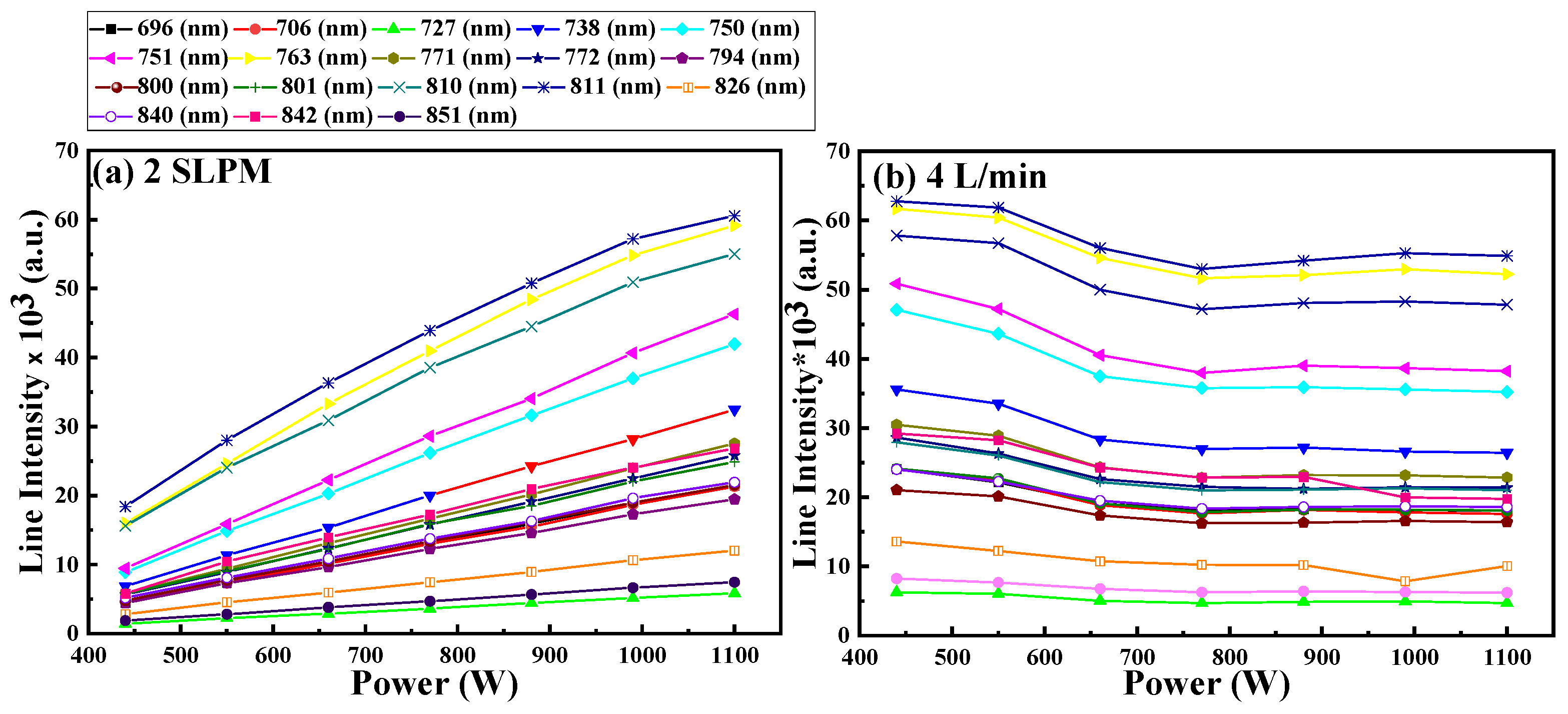
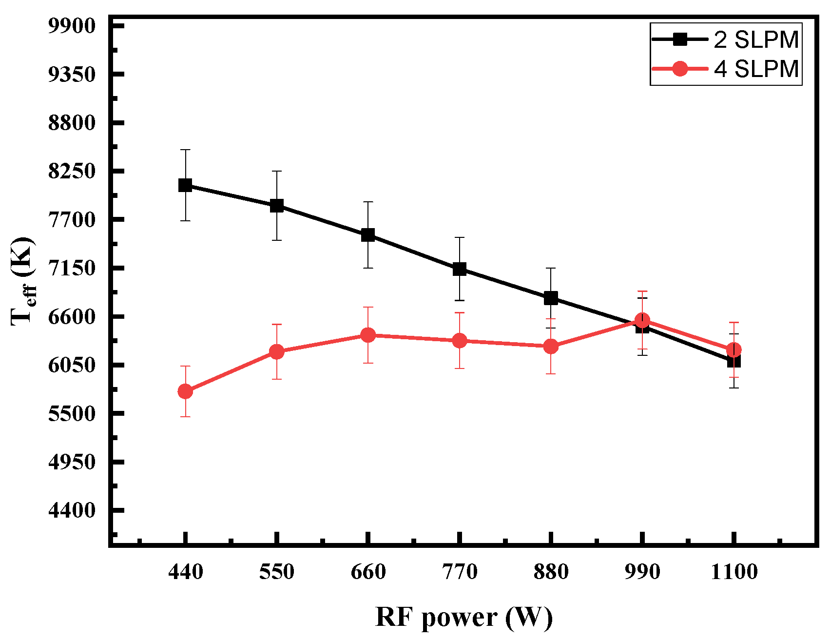
2.1. Excitation Temperature

Boltzmann plot was used to determine the effective electron temperature (Teff) (eV) for the plasma produced from the RF-ICP torch using the following equation:
l n ( I k i λ k i A k i g k ) = E k k B T e f f + C  
where λ k i , A k i , E k , and g k are wavelength (nm), transition probability ( S 1 ), excitation energy (eV), and statistical weight of the upper state, respectively, k B is the Boltzmann constant, and C is a constant. By plotting the left-hand side of Equation (5) [ l n ( I k i λ k i A k i g k ) ]   on the vertical axis and E k on the horizontal axis, the Teff can be derived from the inverse of the slope of the linear fitted line. The Boltzmann plot is an efficient method for determining Teff in atmospheric plasma torches since it does not require a standard source for calibration, and the accuracy increases with the energy range of the emitted lines used in the calculations [54,55,56]. All lines in Table 1 are well isolated and unabsorbed and were chosen to implement the Boltzmann plot. The Boltzmann plots for flow rates of 2 and 4 SLPM and RF power of 440 W are displayed in Figure 3a,b, respectively. The error in the determination of electron temperature is around 20%, and it is generated from the uncertainty in the determination of transition probability ( A k i ) of the Ar* lines and experimental uncertainty [54].
The relationship between electron temperature, RF power, and gas flow rate is a widely recognized phenomenon. Typically, the electrons’ temperature decreases as RF power increases due to the amplified influence of the two-stage ionization process and electron-electron interactions, which are more pronounced at higher plasma densities [54,67,68,69,70]. Simultaneously, electron temperature decreases as the gas flow rate increases. the heightened gas flow rate results in a greater number of gas atoms, leading to increased electron–atom collision probability, thereby increasing plasma density and reducing electron temperature [71]. Figure 4 illustrates this behavior. At a gas flow rate of 2 SLPM, the electrons’ temperature exhibits the expected trend, it decreases with the increase in the RF power. However, at 4 SLPM, the behavior of electrons’ temperature is contrary to the norm, as it increases with the RF power.
The inverse behavior of the electron temperature at 4 SLPM is due to the anomalous skin effect [71]. Only a few electrons significantly contribute to the current density in the anomalous skin effect. These are “glancing” electrons, which spend a significant portion of the field period inside the skin layer after being reflected at modest angles from the plasma barrier. The remaining electrons leave the epidermal layer too quickly to contribute much to the current [72].
The RF-ICP torch is operated in a non-propagating regime. The driving RF field only displays a skin effect by penetrating the plasma within a skin layer (δ) near the antenna [65]. The surface of the plasma is where the induced electric current and radio frequency field are concentrated. Due to electrons’ higher mobility than ions, only electrons are responsible for energy transfer and ionization. The electrons gain energy from the electric field in the skin layer and transfer this energy to the gas atoms to generate more charges and increase the energy conversion rate of the material. Reducing the charge density reduces the efficiency of the torch during the treating process. The charges can be lost by diffusing the energetic electrons to the reactor walls or creating only excited atoms. To reduce the electrons loss through the chamber wall the solution developed to provide an axially high flow of Ar gas to form a cooled barrier gas that separates the plasma from the walls. The second solution is initiating a vortex flow. Vortex flow has the same effect as axially high flow [25]. At 4 SLPM, another energy loss mechanism was detected due to the anomalous skin effect. Most of the electrons with sufficient energy did not contribute to the ionization of the atoms to increase the current density. Therefore, the charge density decreases, as does the energy efficiency of the torch. Anomalous skin is an uncontrollable phenomenon that we can only detect and try to avoid.

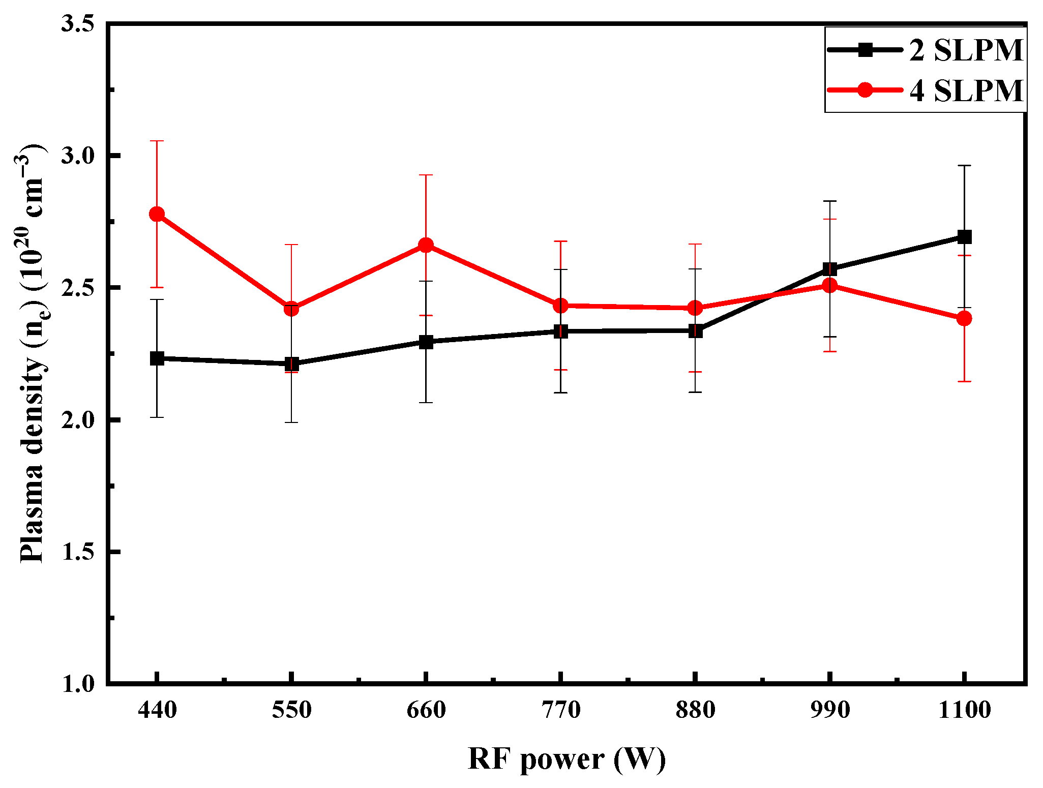
2.2. Electron Density

The measurement of plasma density (ne) is a crucial parameter for assessing energy transfer efficiency in the torch and for determining the state of ionization equilibrium. There are two main approaches to calculating electron density: electrical diagnostics and optical diagnostics. The use of Langmuir probes (single, double, and triple probes) for electron density calculation, which falls under electrical diagnostics, is less accurate at atmospheric pressure where the plasma experiences high collision conditions [57]. On the other hand, the Stark broadening method, a widely employed optical diagnostics technique for electron density calculation [56,57,61], offers a more cost-effective and accessible alternative compared to methods such as Thomson scattering or laser heterodyne interferometry. Its accuracy is notably high within the range of plasma density around 10 16   cm 3 [57].
The broadening of the spectra line (FWHM)   (   Δ λ e x p ) (nm) is a convolution of the Lorentzian profile (Stark, Van der Waals, and Resonance broadening) and Gaussian profile (Doppler and instrumental boarding):
Δ λ e x p = 0.5 Δ λ L + ( 0.5 Δ λ L ) 2 + ( Δ λ G ) 2
In our experiment conditions (pressure and Te 10,000 K), both Resonance broadening and Van Der Waals broadening are negligible [54,57]. The following equation represents the Gaussian profile:
Δ λ G = Δ λ I 2 + Δ λ D 2
where Δ λ I (nm) is the instrumental broadening and Δ λ D (nm) is Doppler broadening. Doppler broadening is given by:
Δ λ D = 7.156 × 10 7 λ o ( T g M A ) 1 2
where λ o,   T g , and M A are the wavelength (nm), the gas temperature (K), and the mass of the emitter (Kg), respectively. By using a Voigt function for deconvolution, we can calculate the Stark broadening ( Δ λ s ) (nm) from Equation (6), and the electron density can be calculated using the empirical formula [57]:
l n N e = 46.516 + 0.992 l n Δ λ s 0.612 l n T e f f
where   ( N e ) ,   ( Δ λ s ), and ( T e f f ) are the plasma density (cm−3), Stark broadening (nm), and electron temperature (eV).
The spectrum of the RF torch contains different lines, i.e., metastable lines and resonance lines. Metastable state lines have proven to be a good indicator of plasma density [73]. Stark broadening calculations in this research utilized a distinct, non-absorptive metastable state Ar* line at 738.3 nm to estimate the plasma density. By fitting the experimental data with the Voigt function using Origin software (2021), as can be seen in Figure 5a–f, the FWHM ( Δ λ e x p ) (nm) of this line is obtained.
Doppler broadening   Δ λ D = 0.008 nm was calculated from Equation (8) at T g   10,000 K, and the instrumental broadening   Δ λ I = 0.66 nm was measured by using a diode-pumped solid-state laser line (660 nm). Table 2 shows   Δ λ e x p , and   Δ λ S , at different RF power and flow rates extracted from the fitting and calculated from Equation (6).
Using Equation (9), we determined the plasma density and graphically represented the relationship between electron density, power, and gas flow rate. The limit of error in plasma density computations was 15% standing for measurement uncertainty [1,52]. Figure 6 illustrates the correlation between plasma density and RF power for gas flow rates of 2 and 4 SLPM. Typically, an increase in RF power and gas flow rate results in higher plasma density [54,68,69,70]. However, Figure 6 demonstrates an unexpected pattern. At 4 SLPM, plasma density decreases as RF power increases. This aligns well with the electron temperature findings.
The relationship between current density ( J ) and electron density ( n e ) in a plasma can be described by the conductivity ( σ ) of the plasma. Specifically, Ohm’s law for a plasma relates current density to electron density and electrical conductivity as follows [74]:
J = σ × E  
where J is the current density ( A / m 2 ), σ is the electrical conductivity of the plasma (S/m), and E   is the electric field strength (V/m).
The electrical conductivity ( σ ) of a plasma depends on several factors, including electron density   ( n e ) , electron mobility ( μ e ), and charge of an electron ( e ). The relationship can be expressed as:
σ = n e × μ e × e
where n e is the electron density ( m 3 ), μ e is the electron mobility ( m 2 / V · s ), and ( e ) is the elementary charge of an electron ( 1.60217663 × 10⁻¹⁹ C).
From Equations (10) and (11), that current density is directly proportional to electron density. Therefore, as the electron density in a plasma increases, assuming other factors remain constant, the current density also increases.
In atmospheric plasma, a condition known as Local Thermodynamic Equilibrium (LTE) prevails, where the electrons’ temperature, gas temperature, and ions’ temperature closely align with one another. The enthalpy of the plasma jet is dependent on the electrons’ temperature, and it rises as the electron temperature increases [75]. Conversely, the energy transferred from the electrical source to the waste is contingent upon the plasma density [76]. Utilizing plasma technology for the treatment of MSW serves a dual purpose: it aims to reduce the waste’s volume for environmental reasons and yields valuable products such as syngas for energy production and useful by-products such as carbon black and carbon nanospheres [63]. The efficiency of this process is closely linked to the properties of the plasma itself. Factors such as the conversion rate (mass and volume reduction), the heating value of the generated gas, and the characteristics and types of by-products produced are all dependent on the properties of the plasma. In the treatment of petroleum sludge, an increase in plasma current led to a significant reduction in both mass (36.87–91.40%) and volume (59.59–94.52%) [76]. The heightened plasma currents were observed to hasten the breakdown of organic components within the sludge. Similarly, during the treatment of fly ash using plasma, an increase in plasma current resulted in a mass reduction of up to 85% [77].
Furthermore, an increase in plasma current led to an elevation in the lower heating value (LHV) of the produced gas from 7.4 to 7.8 MJ/Nm3, while the higher heating value (HHV) decreased from 10.6 to 9.8 MJ/Nm3 in the treatment of petroleum sludge [76]. Similar outcomes were observed in the treatment of municipal solid waste (MSW), where an increase in plasma current led to an increase in the LHV of the generated gas from 7.32 to 9.31 MJ/Nm3 [78].
It was determined that the solid byproduct of waste rubber’s plasma pyrolysis is carbon black. The surface area changed with the power input conditions, ranging from 61 to 70 m2/g. Also, during the pyrolysis of polymers using plasma, carbon black was generated as a residual, and they found that with an increase in the plasma current, the amount of nano-size spherical particles inside the carbon black increased [79].

3. Material and Methods

RF-ICP torch is composed of various elements. It incorporates a copper plasma gas flow diffuser head fitted with two central copper tubes, each having a 0.6 cm inner diameter and a 0.8 cm outer diameter for introducing the plasma-forming gas. Additionally, there are two plasma igniter pins (high voltage feed) mounted on top of the diffuser head to ignite the plasma. To maintain a separation between the plasma and the chamber wall, a high-flow sheath gas inlet tube, made of copper, is connected to one side of the copper torch heads. The plasma chamber itself is constructed with a central quartz tube measuring 1.8 cm in outer diameter, 1.5 cm in inner diameter, and extending for a length of 9 cm. It is encased by a sheath quartz tube with an outer diameter of 2.5 cm, an inner diameter of 2 cm, and a length of 18 cm. This outer quartz tube is surrounded by an isolated water-cooled copper coil consisting of seven turns. The plasma chamber and RF coil are housed within a Teflon shielding cylinder. The RF power is supplied to the coil through an Advanced Energy generator (Model RFX3000, RF GLOBAL SOLUTIONS LTD, Scotland UK), capable of delivering a maximum power output of 1.1 kW and operating at a nominal frequency of 13.56 MHz.
OES data were gathered at different gas flow rates and RF powers using the Ocean Insight Flame-S-XR1-ES spectrometer (Ocean Insight, Orlando, FL, USA), which offers a resolution of 1.7 nm through an optical fiber with a length of 1.5 m and an integration time of 1 ms. To assess the instrument’s spectral broadening, a diode-pumped solid-state laser line (660 nm) was utilized, yielding a value of (∆λI) = 0.66 nm.
It is important to emphasize that, during the optical measurements, only argon gas was introduced through one of the central tubes, and the selection of operating powers and flow rates was based on the stability of the plasma under these specific conditions. A visual representation of the experimental configuration featuring the RF-ICP plasma torch is depicted in Figure 7.

4. Conclusions

We developed an atmospheric RF-ICP torch for the small-scale pyrolysis of mixed waste materials, primarily consisting of paper and polypropylene. Our earlier research extensively characterized the waste material, pinpointing its maximum degradation temperature (ranging from 369.55 to 447.88 °C) and thermal stability (between 381.60 and 393.82 °C) [64]. The main objective of this study was to identify the optimal operational conditions that yield a stable plasma with properties conducive to maximizing profits and efficiency in the pyrolysis process. Given the challenges associated with studying high-temperature plasma, OES was employed to investigate plasma parameters under varying RF power and gas flow rates of 2 and 4 SLPM. Our findings revealed that electron temperature decreased with RF power at a 2 SLPM gas flow rate but increased with RF power at a 4 SLPM rate. This unusual behavior of the electron temperature at a gas flow rate of 4 SLPM is caused by the anomalous skin effect. The anomalous skin effect affects the plasma density as the electrons with effective energy do not contribute to the discharge to generate more charge density and transfer more energy to the material. The anomalous skin effect was not detected before at this range of pressure. Sark broadening calculations using the Ar spectral line at 738.9 nm confirmed the presence of the anomalous skin effect as the plasma density decreased with the power at 4 SLPM.
The enthalpy of the plasma jet depends on the plasma temperature, whereas the heat flux generated by the plasma is linked to the plasma density. Consequently, adjustments in the RF power and flow rate of the plasma have a profound impact on these properties, and these alterations will be mirrored in the material processing. Variations in flow rate and RF power will lead to changes in the conversion rate, calorific value of the produced gas, process duration, by-product characteristics, and formation.
The OSE study for the RF torch proved it can detect unusual phenomena not detected before in that type of discharge condition; this phenomenon causes a decrease in the power efficiency of the torch. In addition, the Ar spectral line at 738.9 nm proved it is sensitive to changes in the plasma density, and it can help in process monitoring, operational optimization, and anomalous detection.
In our forthcoming research, we will integrate the torch into a small-scale pyrolysis system and empirically investigate the influence of RF power, flow rate, plasma temperature, and plasma density on the outcomes of the process. Additionally, we aim to develop a waste treatment strategy based on plasma that is specifically tailored for this type of waste. Also, plasma models can be improved and validated using OES data. By comparing experimental results from OES with theoretical predictions, we can enhance the RF-ICP torch and solve one of the problems of scaling up the torch. RF-ICP scaling up is a challenge as the plasma is more difficult to control, and the dissipated energy increases further.

Author Contributions

Conceptualization, V.D. and I.H.; methodology, M.A.A.; software, M.A.A.; validation, M.A.A. and H.A.G.; formal analysis, M.A.A.; investigation, H.A.G.; resources, V.D., I.H. and H.A.G.; data curation, M.A.A.; writing—original draft preparation, M.A.A.; writing, review and editing, M.A.A. S.A.D. and H.A.G.; visualization, M.A.A.; supervision, H.A.G.; project administration, H.A.G.; funding acquisition, H.A.G. All authors have read and agreed to the published version of the manuscript.

Funding

This research was funded by Natural Sciences and Engineering Research Council of Canada (NSERC) grant number 210466; and Mitacs grant number 215445.

Data Availability Statement

Data is available upon reasonable request.

Conflicts of Interest

Authors have no conflict of interests.

References

  1. Lombardi, L.; Carnevale, E.; Corti, A. A Review of Technologies and Performances of Thermal Treatment Systems for Energy Recovery from Waste. Waste Manag. 2015, 37, 26–44. [Google Scholar] [CrossRef] [PubMed]
  2. Brunner, P.H. WTE: Thermal Waste Treatment for Sustainable Waste Management. In Recovery of Materials and Energy from Urban Wastes; Springer New York: New York, NY, USA, 2019; pp. 523–536. [Google Scholar]
  3. Leckner, B. Process Aspects in Combustion and Gasification Waste-to-Energy (WtE) Units. Waste Manag. 2015, 37, 13–25. [Google Scholar] [CrossRef] [PubMed]
  4. Panepinto, D.; Tedesco, V.; Brizio, E.; Genon, G. Environmental Performances and Energy Efficiency for MSW Gasification Treatment. Waste Biomass Valorization 2015, 6, 123–135. [Google Scholar] [CrossRef]
  5. Manisalidis, I.; Stavropoulou, E.; Stavropoulos, A.; Bezirtzoglou, E. Environmental and Health Impacts of Air Pollution: A Review. Front. Public Health 2020, 8, 505570. [Google Scholar] [CrossRef] [PubMed]
  6. Dong, J.; Tang, Y.; Nzihou, A.; Chi, Y.; Weiss-Hortala, E.; Ni, M. Life Cycle Assessment of Pyrolysis, Gasification and Incineration Waste-to-Energy Technologies: Theoretical Analysis and Case Study of Commercial Plants. Sci. Total Environ. 2018, 626, 744–753. [Google Scholar] [CrossRef] [PubMed]
  7. Safavi, S.M.; Richter, C.; Unnthorsson, R. Dioxin and Furan Emissions from Gasification. In Gasification; Silva, V., Tuna, C.E., Eds.; IntechOpen: Rijeka, Croatia, 2021; p. 5. ISBN 978-1-83968-796-9. [Google Scholar]
  8. Lopes, E.J.; Okamura, L.A.; Yamamoto, C.I. Formation of dioxins and furans during municipal solid waste gasification. Braz. J. Chem. Eng. 2015, 32, 87–97. [Google Scholar] [CrossRef]
  9. Magoua Mbeugang, C.F.; Li, B.; Lin, D.; Xie, X.; Wang, S.; Wang, S.; Zhang, S.; Huang, Y.; Liu, D.; Wang, Q. Hydrogen Rich Syngas Production from Sorption Enhanced Gasification of Cellulose in the Presence of Calcium Oxide. Energy 2021, 228, 120659. [Google Scholar] [CrossRef]
  10. Cortazar, M.; Santamaria, L.; Lopez, G.; Alvarez, J.; Zhang, L.; Wang, R.; Bi, X.; Olazar, M. A Comprehensive Review of Primary Strategies for Tar Removal in Biomass Gasification. Energy Convers. Manag. 2023, 276, 116496. [Google Scholar] [CrossRef]
  11. Yadav, A.; Karmakar, S.; Kar, S.; Kumar, M. Numerical Modelling of a Direct Current Non-Transferred Thermal Plasma Torch for Optimal Performance. Contrib. Plasma Phys. 2023, 63, e202200088. [Google Scholar] [CrossRef]
  12. Li, J.; Liu, K.; Yan, S.; Li, Y.; Han, D. Application of Thermal Plasma Technology for the Treatment of Solid Wastes in China: An Overview. Waste Manag. 2016, 58, 260–269. [Google Scholar] [CrossRef]
  13. Nema, S.K.; Ganeshprasad, K.S. Plasma Pyrolysis of Medical Waste. Curr. Sci. 2002, 83, 271–278. [Google Scholar]
  14. Bosmans, A.; Vanderreydt, I.; Geysen, D.; Helsen, L. The Crucial Role of Waste-to-Energy Technologies in Enhanced Landfill Mining: A Technology Review. J. Clean. Prod. 2013, 55, 10–23. [Google Scholar] [CrossRef]
  15. Rueda, Y.G.; Helsen, L. The Role of Plasma in Syngas Tar Cracking. Biomass Convers. Biorefin. 2020, 10, 857–871. [Google Scholar] [CrossRef]
  16. Mostaghimi, J.; Boulos, M.I. Thermal Plasma Sources: How Well Are They Adopted to Process Needs? Plasma Chem. Plasma Process. 2015, 35, 421–436. [Google Scholar] [CrossRef]
  17. Munir, M.T.; Mardon, I.; Al-Zuhair, S.; Shawabkeh, A.; Saqib, N.U. Plasma Gasification of Municipal Solid Waste for Waste-to-Value Processing. Renew. Sustain. Energy Rev. 2019, 116, 109461. [Google Scholar] [CrossRef]
  18. Pancholi, K.C.; Sen, N.; Singh, K.K.; Vincent, T.; Kaushik, C.P. Transient Heat Transfer during Startup of a Thermal Plasma Chamber: Numerical Insights. Prog. Nucl. Energy 2022, 152, 104371. [Google Scholar] [CrossRef]
  19. Tang, L.; Huang, H. Some observations from studies of rf plasma pyrolysis of waste tires. Chem. Eng. Commun. 2010, 197, 1541–1552. [Google Scholar] [CrossRef]
  20. Khongkrapan, P.; Thanompongchart, P.; Tippayawong, N.; Kiatsiriroat, T. Microwave Plasma Assisted Pyrolysis of Refuse Derived Fuels. Cent. Eur. J. Eng. 2014, 4, 72–79. [Google Scholar] [CrossRef]
  21. Zhang, Q.; Dor, L.; Fenigshtein, D.; Yang, W.; Blasiak, W. Gasification of Municipal Solid Waste in the Plasma Gasification Melting Process. Appl. Energy 2012, 90, 106–112. [Google Scholar] [CrossRef]
  22. Sanito, R.C.; You, S.-J.; Wang, Y.-F. Application of Plasma Technology for Treating E-Waste: A Review. J. Environ. Manag. 2021, 288, 112380. [Google Scholar] [CrossRef]
  23. Gao, P.; Jia, C.-C.; Cao, W.-B.; Wang, C.-C.; Xu, G.-L.; Liang, D.; Cui, Z.-W. Dielectric Properties of AlN/Mo Composite Ceramics Prepared by Spark Plasma Sintering Method at Different Processing Conditions. Rare Met. 2022, 41, 1369–1374. [Google Scholar] [CrossRef]
  24. Muro-Fraguas, I.; Sainz-García, A.; López, M.; Rojo-Bezares, B.; Múgica-Vidal, R.; Sainz-García, E.; Toledano, P.; Sáenz, Y.; González-Marcos, A.; Alba-Elías, F. Antibiofilm Coatings through Atmospheric Pressure Plasma for 3D Printed Surgical Instruments. Surf. Coat. Technol. 2020, 399, 126163. [Google Scholar] [CrossRef] [PubMed]
  25. Boulos, M.I.; Fauchais, P.L.; Pfender, E. The Plasma State. In Handbook of Thermal Plasmas; Springer: Cham, Switzerland, 2016; pp. 1–53. [Google Scholar] [CrossRef]
  26. Conrads, H.; Schmidt, M. Plasma Generation and Plasma Sources. Plasma Sources Sci. Technol. 2000, 9, 441–454. [Google Scholar] [CrossRef]
  27. Reed, T.B. Induction-Coupled Plasma Torch. J. Appl. Phys. 1961, 32, 821–824. [Google Scholar] [CrossRef]
  28. Fazekas, P.; Czégény, Z.; Mink, J.; Bódis, E.; Klébert, S.; Németh, C.; Keszler, A.M.; Károly, Z.; Szépvölgyi, J. Decomposition of Poly(Vinyl Chloride) in Inductively Coupled Radiofrequency Thermal Plasma. Chem. Eng. J. 2016, 302, 163–171. [Google Scholar] [CrossRef]
  29. Major, K.; Veilleux, J.; Brisard, G. Lithium Iron Phosphate Powders and Coatings Obtained by Means of Inductively Coupled Thermal Plasma. J. Therm. Spray Technol. 2016, 25, 357–364. [Google Scholar] [CrossRef]
  30. Darthout, É.; Gitzhofer, F. Thermal Cycling and High-Temperature Corrosion Tests of Rare Earth Silicate Environmental Barrier Coatings. J. Therm. Spray Technol. 2017, 26, 1823–1837. [Google Scholar] [CrossRef]
  31. Darthout, É.; Gitzhofer, F. Structure Stabilization by Zirconia Pinning Effect of Y2Si2O7 Environmental Barrier Coatings Synthesized by Solution Precursor Plasma Spraying Process. Surf. Coat. Technol. 2017, 309, 1081–1088. [Google Scholar] [CrossRef]
  32. Deng, Z.-Q.; Mao, J.; Liu, M.; Deng, C.-M.; Ma, J.-T. Regional Characteristic of 7YSZ Coatings Prepared by Plasma Spray-Physical Vapor Deposition Technique. Rare Met. 2021, 40, 3308–3315. [Google Scholar] [CrossRef]
  33. Berghaus, J.O.; Meunier, J.L.; Gitzhofer, F. Monitoring and Control of RF Thermal Plasma Diamond Deposition via Substrate. Meas. Sci. Technol. 2003, 15, 161. [Google Scholar] [CrossRef]
  34. Aldeeb, M.A.; Morgan, N.; Abouelsayed, A.; Amin, K.M.; Hassaballa, S. Correlation of Acetylene Plasma Discharge Environment and the Optical and Electronic Properties of the Hydrogenated Amorphous Carbon Films. Diam. Relat. Mater. 2019, 96, 74–84. [Google Scholar] [CrossRef]
  35. Todorovic-Marković, B.; Marković, Z.; Mohai, I.; Károly, Z.; Gál, L.; Föglein, K.; Szabó, P.T.; Szépvölgyi, J. Efficient Synthesis of Fullerenes in RF Thermal Plasma Reactor. Chem. Phys. Lett. 2003, 378, 434–439. [Google Scholar] [CrossRef]
  36. Keszler, A.M.; Kováts, É.; Bódis, E.; Károly, Z.; Szépvölgyi, J. Effect of Metallic and Non-Metallic Additives on the Synthesis of Fullerenes in Thermal Plasma. Condens. Matter 2022, 7, 44. [Google Scholar] [CrossRef]
  37. Tong, J.B.; Lu, X.; Liu, C.C.; Pi, Z.Q.; Zhang, R.J.; Qu, X.H. Numerical Simulation and Prediction of Radio Frequency Inductively Coupled Plasma Spheroidization. Appl. Therm. Eng. 2016, 100, 1198–1206. [Google Scholar] [CrossRef]
  38. Yu, C.; Zhou, X.; Wang, D.; Van Linh, N.; Liu, W. Study on the RF Inductively Coupled Plasma Spheroidization of Refractory W and W-Ta Alloy Powders. Plasma Sci. Technol. 2017, 20, 014019. [Google Scholar] [CrossRef]
  39. Park, J.Y.; Park, K.B.; Kang, J.W.; Kim, H.G.; Hwang, N.M.; Park, H.K. Spheroidization Behavior of Water-Atomized 316 Stainless Steel Powder by Inductively-Coupled Thermal Plasma. Mater. Today Commun. 2020, 25, 101488. [Google Scholar] [CrossRef]
  40. Kim, K.H.; Choi, H.; Han, C. Tungsten Micropowder/Copper Nanoparticle Core/Shell-Structured Composite Powder Synthesized by Inductively Coupled Thermal Plasma Process. Metall. Mater. Trans. A 2017, 48, 439–445. [Google Scholar] [CrossRef]
  41. Dhamale, G.D.; Tak, A.K.; Mathe, V.L.; Ghorui, S. Nucleation and Growth of Y2O3 Nanoparticles in a RF-ICTP Reactor: A Discrete Sectional Study Based on CFD Simulation Supported with Experiments. J. Phys. D Appl. Phys. 2018, 51, 255202. [Google Scholar] [CrossRef]
  42. Oh, J.-W.; Na, H.; Cho, Y.S.; Choi, H. In Situ Synthesis of Bimetallic Tungsten-Copper Nanoparticles via Reactive Radio-Frequency (RF) Thermal Plasma. Nanoscale Res. Lett. 2018, 13, 220. [Google Scholar] [CrossRef]
  43. Zhang, X.; Hayashida, R.; Tanaka, M.; Watanabe, T. Synthesis of Carbon-Coated Silicon Nanoparticles by Induction Thermal Plasma for Lithium Ion Battery. Powder Technol. 2020, 371, 26–36. [Google Scholar] [CrossRef]
  44. Kim, K.S.; Couillard, M.; Shin, H.; Plunkett, M.; Ruth, D.; Kingston, C.T.; Simard, B. Role of Hydrogen in High-Yield Growth of Boron Nitride Nanotubes at Atmospheric Pressure by Induction Thermal Plasma. ACS Nano 2018, 12, 884–893. [Google Scholar] [CrossRef]
  45. Kim, K.S.; Kingston, C.T.; Ruth, D.; Barnes, M.; Simard, B. Synthesis of High Quality Single-Walled Carbon Nanotubes with Purity Enhancement and Diameter Control by Liquid Precursor Ar–H2 Plasma Spraying. Chem. Eng. J. 2014, 250, 331–341. [Google Scholar] [CrossRef]
  46. Li, J.; Hu, R.; Qu, H.; Su, Y.; Wang, N.; Su, H.; Gu, X. Radio-Frequency Thermal Plasma-Induced Novel Chainmail-like Core-Shell MoO2 as Highly Stable Catalyst for Converting Syngas to Higher Alcohols. Appl. Catal. B 2019, 249, 63–71. [Google Scholar] [CrossRef]
  47. Takigawa, A.; Kim, T.-H.; Igami, Y.; Umemoto, T.; Tsuchiyama, A.; Koike, C.; Matsuno, J.; Watanabe, T. Formation of Transition Alumina Dust around Asymptotic Giant Branch Stars: Condensation Experiments Using Induction Thermal Plasma Systems. Astrophys. J. Lett. 2019, 878, L7. [Google Scholar] [CrossRef]
  48. Tanaka, Y. Recent Development of New Inductively Coupled Thermal Plasmas for Materials Processing. Adv. Phys. X 2021, 6, 1867637. [Google Scholar] [CrossRef]
  49. Causa, F.; Gittini, G.; Minelli, D.; Mellera, V.; Uccello, A.; Nardone, A.; Ripamonti, F. Plasma Parameters Profiles from Langmuir Probe Measurements in Low-Density, Low-Temperature Plasmas in an Axial Magnetic Field. Plasma Sources Sci. Technol. 2022, 31, 075007. [Google Scholar] [CrossRef]
  50. Passoth, E.; Kudrna, P.; Csambal, C.; Behnke, J.F.; Tichý, M.; Helbig, V. An Experimental Study of Plasma Density Determination by a Cylindrical Langmuir Probe at Different Pressures and Magnetic Fields in a Cylindrical Magnetron Discharge in Heavy Rare Gases. J. Phys. D Appl. Phys. 1997, 30, 1763. [Google Scholar] [CrossRef]
  51. Mascali, D.; Gambino, N.; Miracoli, R.; Gammino, S.; Torrisi, L.; Maimone, F.; Tumino, L. Plasma Parameters Measurements by Means of Langmuir Probe. Radiat. Eff. Defects Solids 2008, 163, 471–478. [Google Scholar] [CrossRef]
  52. Lindner, J.; Ross, U.; Roddatis, V.; Jooss, C. Langmuir Analysis of Electron Beam Induced Plasma in Environmental TEM. Ultramicroscopy 2023, 243, 113629. [Google Scholar] [CrossRef] [PubMed]
  53. Giannakaris, N.; Gürtler, G.; Stehrer, T.; Mair, M.; Pedarnig, J.D. Optical Emission Spectroscopy of an Industrial Thermal Atmospheric Pressure Plasma Jet: Parametric Study of Electron Temperature. Spectrochim. Acta Part B Spectrosc. 2023, 207, 106736. [Google Scholar] [CrossRef]
  54. Ohno, N.; Razzak, M.A.; Ukai, H.; Takamura, S.; Uesugi, Y. Validity of Electron Temperature Measurement by Using Boltzmann Plot Method in Radio Frequency Inductive Discharge in the Atmospheric Pressure Range. Plasma Fusion Res. 2006, 1, 28. [Google Scholar] [CrossRef]
  55. Zhang, H.; Yuan, F.; Chen, Q. Optical Emission Spectroscopy Diagnostics of Atmospheric Pressure Radio Frequency Ar-H2Inductively Coupled Thermal Plasma. IEEE Trans. Plasma Sci. 2020, 48, 3621–3628. [Google Scholar] [CrossRef]
  56. Tu, X.; Chéron, B.G.; Yan, J.H.; Cen, K.F. Electrical and Spectroscopic Diagnostic of an Atmospheric Double Arc Argon Plasma Jet. Plasma Sources Sci. Technol. 2007, 16, 803. [Google Scholar] [CrossRef]
  57. Nikiforov, A.Y.; Leys, C.; Gonzalez, M.A.; Walsh, J.L. Electron Density Measurement in Atmospheric Pressure Plasma Jets: Stark Broadening of Hydrogenated and Non-Hydrogenated Lines. Plasma Sources Sci. Technol. 2015, 24, 034001. [Google Scholar] [CrossRef]
  58. Chen, C.; Fu, W.; Zhang, C.; Lu, D.; Han, M.; Yan, Y. Langmuir Probe Diagnostics with Optical Emission Spectrometry (OES) for Coaxial Line Microwave Plasma. Appl. Sci. 2020, 10, 8117. [Google Scholar] [CrossRef]
  59. Wu, J.; Zhang, P.; Yu, D.; Zhang, S.; Xin, Q.; Wan, Y. Monitoring and Diagnosis of the Inductively Coupled Atmospheric Pressure Plasma Jet for Deterministic Optical Processing. Optik 2020, 214, 164815. [Google Scholar] [CrossRef]
  60. Griem, H.R. Stark Broadening. Adv. At. Mol. Phys. 1976, 11, 331–359. [Google Scholar] [CrossRef]
  61. Sadeghzadeh Lari, E.; Ranjbar Askari, H.; Meftah, M.T.; Shariat, M. Calculation of Electron Density and Temperature of Plasmas by Using New Stark Broadening Formula of Helium Lines. Phys. Plasmas 2019, 26, 023519. [Google Scholar] [CrossRef]
  62. Christova, M.; Castanos-Martinez, E.; Calzada, M.D.; Kabouzi, Y.; Luque, J.M.; Moisan, M. Electron Density and Gas Temperature from Line Broadening in an Argon Surface-Wave-Sustained Discharge at Atmospheric Pressure. Appl. Spectrosc. 2004, 58, 1032–1037. [Google Scholar] [CrossRef]
  63. Bhatt, K.P.; Patel, S.; Upadhyay, D.S.; Patel, R.N. A Critical Review on Solid Waste Treatment Using Plasma Pyrolysis Technology. Chem. Eng. Process.-Process Intensif. 2022, 177, 108989. [Google Scholar] [CrossRef]
  64. Galiwango, E.; Gabbar, H.A. Synergistic Interactions, Kinetic and Thermodynamic Analysis of Co-Pyrolysis of Municipal Paper and Polypropylene Waste. Waste Manag. 2022, 146, 86–93. [Google Scholar] [CrossRef]
  65. Ganguli, A.; Tarey, R. Understanding Plasma Sources. Curr. Sci. 2002, 83, 279–290. [Google Scholar]
  66. Aldeeb, M.A.; Morgan, N.; Abouelsayed, A.; Amin, K.M.; Hassaballa, S. Electrical and Optical Characterization of Acetylene RF CCP for Synthesis of Different Forms of Hydrogenated Amorphous Carbon Films. Plasma Chem. Plasma Process. 2020, 40, 387–406. [Google Scholar] [CrossRef]
  67. Abbass, Q.; Ahmed, N.; Ahmed, R.; Baig, M.A. A Comparative Study of Calibration Free Methods for the Elemental Analysis by Laser Induced Breakdown Spectroscopy. Plasma Chem. Plasma Process. 2016, 36, 1287–1299. [Google Scholar] [CrossRef]
  68. Younus, M.; Rehman, N.U.; Shafiq, M.; Naeem, M.; Zaka-Ul-Islam, M.; Zakaullah, M. Evolution of Plasma Parameters in an Ar–N 2 /He Inductive Plasma Source with Magnetic Pole Enhancement. Plasma Sci. Technol. 2017, 19, 025402. [Google Scholar] [CrossRef]
  69. Godyak, V.A. Electrical and Plasma Parameters of ICP with High Coupling Efficiency. Plasma Sources Sci. Technol. 2011, 20, 025004. [Google Scholar] [CrossRef]
  70. Godyak, V.A.; Piejak, R.B.; Alexandrovich, B.M. Electron Energy Distribution Function Measurements and Plasma Parameters in Inductively Coupled Argon Plasma. Plasma Sources Sci. Technol. 2002, 11, 525–543. [Google Scholar] [CrossRef]
  71. Jun-Feng, Z.; Xin-Chao, B.; Qiang, C.; Fu-Ping, L.; Zhong-Wei, L. Diagnosis of Methane Plasma Generated in an Atmospheric Pressure DBD Micro-Jet by Optical Emission Spectroscopy. Chin. Phys. Lett. 2009, 26, 035203. [Google Scholar] [CrossRef]
  72. Kolobov, V. The Anomalous Skin Effect in Bounded Systems. In Electron Kinetics and Applications of Glow Discharges; Kluwer Academic Publishers: Boston, MA, USA, 1995; pp. 293–311. [Google Scholar]
  73. Boffard, J.B.; Jung, R.O.; Lin, C.C.; Wendt, A.E. Measurement of Metastable and Resonance Level Densities in Rare-Gas Plasmas by Optical Emission Spectroscopy. Plasma Sources Sci. Technol. 2009, 18, 035017. [Google Scholar] [CrossRef]
  74. Nijdam, S.; Teunissen, J.; Ebert, U. The Physics of Streamer Discharge Phenomena. Plasma Sources Sci. Technol. 2020, 29, 103001. [Google Scholar] [CrossRef]
  75. Tamošiūnas, A.; Valatkevičius, P.; Valinčius, V.; Grigaitienė, V.; Kavaliauskas, Ž. Diagnostic Methods Used for Atmospheric Pressure Thermal Arc Plasma. Phys. Scr. 2014, T161, 014059. [Google Scholar] [CrossRef]
  76. Ali, A.M.; Abu Hassan, M.A.; Ibrahim, R.R.K.; Jalil, A.A.; Mat Nayan, N.H.; Abdulkarim, B.I.; Sabeen, A.H. Analysis of Solid Residue and Flue Gas from Thermal Plasma Treatment of Petroleum Sludge. J. Environ. Chem. Eng. 2019, 7, 103207. [Google Scholar] [CrossRef]
  77. Pourali, M. Application of Plasma Gasification Technology in Waste. to Energy—Challenges and Opportunities. IEEE Trans. Sustain. Energy 2010, 1, 125–130. [Google Scholar] [CrossRef]
  78. Balas, M.; Lisy, M.; Kracik, P.; Pospisil, J. Municipal solid waste gasification within waste-to-energy processing. MM Sci. J. 2017, 2017, 1783–1788. [Google Scholar] [CrossRef]
  79. Huang, H.; Tang, L.; Wu, C.Z. Characterization of Gaseous and Solid Product from Thermal Plasma Pyrolysis of Waste Rubber. Environ. Sci. Technol. 2003, 37, 4463–4467. [Google Scholar] [CrossRef] [PubMed]
Figure 1. (a) Argon emission spectra at flow rate 2 SLPM and 440 RF power. (b) Argon emission spectra at flow rate 4 SLPM and 440 RF power.
Recycling 09 00020 g001
Figure 2. (a) Shows the Ar* lines intensity variation with the RF power at 2 SLPM. (b) Shows the Ar* lines intensity variation with the RF power at 4 SLPM.
Recycling 09 00020 g002
Figure 3. (a) Boltzmann plot for emission lines at flow rate 2 SLPM and 440 W RF power. (b) Boltzmann plot for emission lines at flow rate 4 SLPM and 440 W RF power.
Recycling 09 00020 g003
Figure 4. Electron temperature variation with RF power at 2 and 4 SLPM Ar gas flow rates.
Recycling 09 00020 g004
Figure 5. (a,c,e) Ar* (738.3 nm) line fitted with the Voigt function at flow rate 2 SLPM and 440, 770, 1100 RF powers, respectively. (b,d,f) Ar* (738.3 nm) line fitted with the Voigt function at flow rate 4 SLPM and 440, 770, 1100 RF powers, respectively.
Recycling 09 00020 g005
Figure 6. Shows the variation of the plasma density (ne) with RF power at two different Ar flow rates 2 and 4 SLPM.
Recycling 09 00020 g006
Figure 7. Experimental setup of the Ar spectrum measurements.
Recycling 09 00020 g007
Table 1. The wavelength, excitation energy (Ek), transition probability (Aik), and statistical weight (gk) for the lines that appeared in the region of 696–851 nm.
λ (nm)Ek (eV)Aik (106 S−1)gk
69613.3286.403
70613.3023.805
72713.3281.833
73813.3028.505
75013.479451
75113.273401
76313.172245
77113.1535.203
77213.32811.73
79413.28318.63
80013.172495
80113.0959.305
81013.153253
81113.076337
82613.32815.33
84013.30222.35
84213.09521.55
85113.28313.93
Table 2. Contains measured   Δ λ e x p of the Ar* line 738.3 nm and the calculated   Δ λ S .
2 SLPM4 SLPM
Power (W)   Δ λ e x p
(nm)
  Δ λ s (nm)Power (W) Δ λ e x p (nm)   Δ λ s (nm)
4401.4311.1264401.4401.138
5501.4061.0965501.3581.037
6601.4151.1086601.4611.162
7701.4021.0917701.3721.055
8801.3771.0618801.3631.044
9901.4361.1339901.4191.113
11001.4451.14311001.3461.023
Disclaimer/Publisher’s Note: The statements, opinions and data contained in all publications are solely those of the individual author(s) and contributor(s) and not of MDPI and/or the editor(s). MDPI and/or the editor(s) disclaim responsibility for any injury to people or property resulting from any ideas, methods, instructions or products referred to in the content.

