Article

A Sustainable Solution with Improved Chemical Resilience Using Repurposed Glass Fibers for Sewage Rehabilitation Pipes

by
Devanand Chelot
,
Shivnarain Ravichandran
and
Priyank Upadhyaya
*
Department of Mechanical Engineering, Birla Institute of Technology & Science Pilani, Dubai Campus, Dubai P.O. Box 345055, United Arab Emirates
*
Author to whom correspondence should be addressed.
Recycling 2024, 9(2), 28; https://doi.org/10.3390/recycling9020028
Submission received: 28 January 2024 / Revised: 22 March 2024 / Accepted: 27 March 2024 / Published: 31 March 2024

Abstract

:
This paper introduces a sustainable sewage rehabilitation solution, utilizing repurposed glass fibers for enhanced chemical resilience and environmental conservation. The approach involves dividing a unitary pipe into segments, assembled during commissioning, aiming to reduce installation and transportation costs, particularly in less accessible areas. Each pipe segment comprises a multi-layered glass fiber composite sandwich, joined by an adhesive reinforced with recycled glass fibers. The glass fiber-reinforced plastic (GFRP) pipe features a core of blended sand impregnated with resin, an outer layer for impact resistance, and an inner layer to prevent corrosion. Chemical resilience is assessed through a 10,000 h strain corrosion study exposing both unitary and two-piece circular GFRP pipes to sulfuric acid in a deflected condition. An apparent hoop tensile test evaluates mechanical integrity before and after exposure. The experimental results reveal that the two-piece pipe with a tongue and groove joint (TGJ) with recycled glass fiber adhesive exhibits superior long-term bending stress and failure strain % compared to unitary pipes. This enhancement is attributed to the TGJ’s improved load-bearing capability and chemical resistance. The failure strain % of the two-piece pipe (1.697%) is higher compared to the unitary pipe (1.2613%). The long-term bending stress of the two-piece pipe obtained is 119.94 MPa whereas the unitary pipe reaches 93.48 MPa at the 50-year mark. The cost analysis supports the adoption of the two-piece pipe over unitary pipes due to a 40% reduction in carbon emissions and transportation cost. The novelty lies in the utilization of multi-piece pipes with enhanced chemical resilience, achieved through the incorporation of milled fiberglass reinforcements in the TGJ. Strain corrosion tests take a long time to perform; hence, an accelerated test is needed to improve the current recommended testing standard.

Graphical Abstract

1. Introduction

Sewage pipes are essential to the effective and secure transportation of wastewater from residences, workplaces, and industry to treatment facilities. These subterranean pipe networks are essential for maintaining appropriate sewage disposal and avoiding contaminated water sources, protecting public health. However, these pipes may deteriorate due to age, corrosion, ground changes, and greater consumption, which could cause leaks, clogs, and structural failures. Numerous researchers have studied mechanical loading and the chemical environment. Since civil constructions are frequently exposed to moisture over their lifetime, it is imperative to comprehend how water affects GFRP composites. In tubular rings, moisture dispersion was found to be slower than in coupons by Ellyin et al. [1]; however, once penetration was achieved, moisture quickly permeated the resin, leading to deterioration [2]. To overcome these difficulties, sewage pipeline rehabilitation has become increasingly important. This is carried out by restoring hydraulic efficiency, structural integrity, and functioning using cutting-edge methods and technology.
A wide range of tasks are included in the rehabilitation process, such as relining, cleaning, repair, and inspection. The condition of the pipeline is assessed using inspection techniques like robotic equipment and closed-circuit television (CCTV) cameras. Cleaning techniques that remove sediment and blockages, such as hydro-jetting and mechanical scraping, restore flow capacity. In comparison with conventional replacement techniques, this strategy offers financial savings, lessens the impact on the environment, and minimizes disturbances to communities.
Buried pipes undergo stress by backfill loads and, in the event of a pressure main, by internal pressure [3]. Extended exposure to these kinds of in-service pressures can lead to structural deterioration that necessitates regular maintenance, particularly in older sewage pipelines. Ibrahim Y. Hakeem et al. [4] investigated the crashworthiness characteristics of Glass reinforced plastic (GRP) pipes by analyzing how the winding angle of fibers and the thickness of the tube wall influence energy absorption in quasi-static compression tests. The study showed a gradual failure pattern in specimens with [±90] orientation across various layer configurations. Among these, the [±90]3 specimen, with three layers, demonstrated superior performance in both load-carrying capacity and energy absorption. The GRP pipe’s large size and irregular shape make typical non-disruptive techniques of restoration difficult. Because they are resistant to corrosion from various kinds of chemicals, composite pipes, such as GFRP or fiber-reinforced polymer (FRP) pipes, are recommended as the perfect alternative for sewer rehabilitation [5]. With a life expectancy of more than a century, GFRPs are lightweight in comparison to most other materials. The greater chemical resistance of GFRPs in comparison to traditional steel and concrete pipes is another significant benefit [6]. Hybrid composites are predominantly becoming common for underground construction industry due to their enhanced strength and bespoke engineering advantages. Emrah Madenci et al. [7] studied the buckling characteristics of FRP composites with the incorporation of carbon nanotubes (CNTs). The experimental results indicated that the inclusion of 0.3% CNTs improved the composite’s buckling resistance. Furthermore, it is noteworthy that the average load-carrying capacity under the clamped–clamped boundary condition was 268% higher in the CNT samples and 282% higher in the neat samples compared to the simple–simple condition. Pultruded GFRP composites are favored in civil engineering for their lightness, corrosion resistance, and strength. Y.O. Özkılıç et al. [8] explored the behavior of pultruded GFRP in reinforced concrete beams, emphasizing stirrup spacing. Eight beams, including one reference and seven hybrids with varied stirrup spacings, were tested under four-point loading. Wrapping hybrid beams with GFRP composites increased load and energy capacities, preventing brittle failure, suggesting a need to strengthen unidirectional pultruded profiles with 90° GFRP wrapping for ductile behavior.
One of the key challenges with using GFRP composites in civil structures is how exposure to chemicals and water affects the materials’ longevity. Moreover, it is equally crucial to study how alkali affects the durability of GFRP composites, given the high alkaline nature of concrete. Composite pipes retain their structural integrity and functionality in corrosive conditions in contrast to metal pipes, which can corrode when exposed to hostile substances. Composite pipes can tolerate a variety of chemicals by tailoring the reinforcement materials and resin matrix, increasing their longevity and lowering maintenance and replacement costs. Chemical-resistant composite pipes are ideal for a variety of industries, such as water management and chemical processing, since they guard against contamination and preserve the purity of fluids being conveyed. Additionally, the flexibility, efficiency of installation, resistance to corrosion, lifespan, structural integrity, and sustainability of GFRP pipes make them extremely beneficial [5,6]. Because of its segmented form, less excavation and disruption are required when adjusting and customizing it to different sewer geometries. Their ability to withstand corrosion guarantees long-term durability and reduces maintenance requirements. Furthermore, because they are lightweight, they produce less waste and emit less carbon emissions, supporting environmental sustainability. As a result, sewage pipeline restoration is crucial to preserving public health and avoiding environmental contamination. Most importantly, GFRP pipes are an affordable and sustainable option that provide chemical resistance, structural integrity, and longevity. These qualities make them ideal for a range of industrial uses and guarantee the secure and effective transportation of chemicals.
Over the past twenty years, a comprehensive analysis of GFRP composites’ durability with respect to their application in civil infrastructure has been conducted. Referencing [9,10], the results of these studies have been carefully combined. Understanding how environmental elements including moisture, alkali, chloride, temperature swings, and wetting–drying cycles affect GFRP composites has been the main area of focus. The way in which these environmental factors affect the tensile and bond properties of GFRP composites is of particular significance.
The California Greenbook [11] for sewage rehabilitation and Australian standard AS 3572.2 [12] have created a chemical resistance guide to assist engineers in selecting the different chemical environments in which the samples should be exposed to during weight loss and tensile testing. Similar studies on strain corrosion are available in the literature for unitary pipes [13,14], but to best of our knowledge, strain corrosion study for multi-piece pipes is not yet available. In the current work, a comparative strain corrosion test [15] was performed to study the deterioration of a life-size pipe over time for a unitary and a two-piece pipe. The inside of the pipe surface was exposed to sulfuric acid for 10,000 h. Following chemical exposure, one pipe from each of the unitary and two-piece pipe configurations was selected for an apparent hoop tensile test [
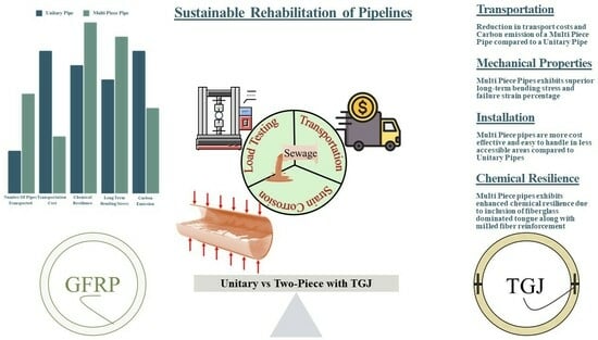
16] to assess the strength change in the pipe samples before and after exposure. The proposed multi-piece approach not only aims to improve the long-term chemical resistance of sandwich GFRP pipes when compared to unitary pipes, but it also makes it more sustainable by lowering shipping costs and recycling fiberglass waste as reinforcement.

2. Cost Analysis

The sewage rehabilitation process is organized into three easy steps: pipe manufacturing, pipe transportation, and pipe installation on-site. When comparing the cost of a project for a unitary versus multi-piece solution, the production cost remains the same because the same hand layup procedure is employed to create the GFRP pipe. Pipe transport is a major concern in terms of cost and carbon emissions. Various techniques of installation are used based on the location and accessibility of the rehabilitation site. The following section presents a detailed comparison of transportation costs for unitary versus multi-piece solutions followed by an example case with an accessibility issue to highlight the applicability of multi-piece solutions.

2.1. Transportation Cost

The various stacking methods employed for loading pipes are essential considerations in the context of efficient and cost-effective pipe shipments. Therefore, selecting an appropriate stacking method holds significance in optimizing the transportation cost. For sea transportation, the standard 12.192 m container is used which has a length (L) of 12.024 m, width (W) of 2.340 m, and height (H) of 2.585 m, resulting in a container volume of 72.732 m3.
The analysis shows the transportation of rehabilitation pipes for an underground sewer of 2440 linear meter pipes from Dubai to Los Angeles and possible stacking methods for a unitary and two-piece circular pipe with an outer diameter (OD) of 2 m, inner diameter (ID) of 1.94 m and a wall thickness of 0.03 m. The unit length of each pipe is 2.44 m.

2.1.1. Unitary Pipes

Horizontal stacking involves two primary approaches when the length of the pipe is either aligned with the length or the width of the container. In the first horizontal stacking-1 (HS1) approach, the analysis is carried out for aligning the length of the pipe along the width of the container and stacking them along the length of the container as shown in Figure 1a. Given that the length of the pipes is 2.44 m, surpassing the container’s width by 0.1 m, it is evident that the pipes can only be stacked in an inclined position vertically or in a horizontal position at an angle θ.
The pipe axis is in the xz plane, and the maximum quantity of pipes which could be stacked in HS1 is six, based on the dimensions of the container and the OD of the pipe, totaling a loaded length of 14.64 m, but such stacking results in a singular point of contact, situated both on the floor and the side wall of the container, causing stress concentrations that could potentially lead to localized damage of the pipe. Additionally, this arrangement increases the packing cost as it requires a very complicated and strong structure to hold the pipe’s weight, and this also increases the complexity of loading and unloading processes of the pipes from the containers. Therefore, stacking pipes at an inclined position is not a feasible solution.
In the horizontal stacking-2 (HS2), the analysis is carried out for aligning the length of the pipe along the length of the container and stacking them along the width of the container as shown in Figure 1b. The maximum number of pipes that can be accommodated is determined by considering the length of the container and the unit length, which is only four in this scenario, totaling a loaded length of 9.76 m.
In another possible horizontal stacking 1/2 (HS12), the pipe axis is parallel to the bed of the container, and pipes are placed diagonally. Based on the container width and the OD of the pipe, it is determined that the maximum number of pipes that can be stacked in HS12 is only five, totaling a loaded length of 12.2 m. Since the pipes are stacked diagonally, there is a substantial amount of space unused. It is crucial to note that in both horizontal stacking methods, the pipes, composed of GFRP material, experience compression, which may lead to variations in the dimensions, causing installation challenges.
Vertical stacking (VS) involves placing pipes along the height of the container in a standing position. In this case, the maximum number of pipes that can be accommodated in a single column is determined by considering the length of the container and the OD of the pipe. Since the width of the container limits the number of columns to one, the calculation indicates that a total of six pipes can be vertically stacked along the length of the container totaling a loaded length of 14.64 m. As an added benefit, when pipes are placed vertically, there is no compression or deviation from the actual dimensions, highlighting the advantages of vertical stacking in preserving the integrity of the shipped pipes.

2.1.2. Two-Piece Pipes

Here, a two-piece circular pipe is considered with identical geometry (OD, ID, wall thickness, and length). Considering the risk of structural damage that may occur during the transit due to rough seas, the packaging of two-piece pipes is carried out only in pallets, therefore negating the possibility of packaging them in HS1, HS12, and HS2 configurations. Following the VS configuration, the maximum number of pipes that can be loaded into a 12.192 m container increases to 10, resulting in a total loaded length of 24.40 m, as shown in Figure 2. This implies that a combined length of 24.40 m of two-piece circular pipes, each featuring an ID of 1.94 m and a wall thickness of 0.03 m, can be efficiently transported in a single truck carrying a 12.192 m container.
In this situation, only five pallets can be accommodated due to insufficient space for the sixth pallet. Each pallet has a wood thickness of 0.15 m, and with five pallets, a total of 1.5 m is already occupied by the pallets. The pipes will require 10 m of space, resulting in a total utilization of 11.5 m space within a 12 m container. The remaining gap inside the container is only 0.5 m. Furthermore, if pallets are designed to horizontally stack the pipes, this would result in elevated lengths and breadths, causing a shift in the center of mass of the pallets. This in turn would make it challenging to load and unload the pallets using forklifts. On the other hand, arranging pipes vertically on the pallets, with dimensions of 2 × 2 for length and breadth, ensures that the center of mass of the pallets remains stable, simplifying the loading process.
It is not feasible to reduce the number of pallets by increasing their length because, in an optimal scenario, the length of the shoe used by a 5-ton forklift for loading and unloading pallets is approximately 1.5 m, while for a 10-ton forklift, it is approximately 2.2 m. Consequently, enlarging the pallet size to accommodate more pipes may pose challenges in the loading and unloading process.
Notably, there is a 60% increase in length per panel transported in a 12.192 m container for a two-piece circular pipe, underscoring the heightened efficiency and capacity.

2.1.3. Fuel and Consumption Cost

In comparing the fuel consumption and carbon emissions, the context is the transportation of a container from Dubai to Los Angeles by ship. The average sea transportation cost of a container from Dubai to Los Angeles is USD 6500. To transport 2440 m of unitary pipes in a 12.192 m container, HS12 would require 200 containers, HS2 would require 250 containers, and VS would require 167 containers. The HS1 configuration is not taken into consideration as the pipes will be aligned in the xz plane, and therefore, the pipes will undergo point loading which can result in pipe damage during transit.
The total cost is USD 1,300,000, USD 1,625,000, and USD 1,085,500 for HS12, HS2, and VS, respectively. For the transportation of two-piece pipes, only 100 containers of 12.192 m length are required. The total cost for the transportation of two-piece 2440 linear meter pipes is USD 650,000, thereby reducing the transportation cost by USD 435,500 and showing a reduction of 40% cost for transporting two-piece pipes.
The carbon emission data obtained from a reputable logistics company located in Dubai for a journey from Dubai to Los Angeles (20,898 km) show a carbon emission of 1787 kg. The 2019th version of the Practical Guide for Calculating Greenhouse Gas (GHG) Emissions has shown that the emission factor of heavy fuel oil is 3.114 kg CO2/kg [17]. Therefore, fuel consumption is calculated by dividing the carbon emission for the journey by 3.114 kg CO2/kg.
The fuel consumption for the entire journey is calculated to be 573.859 kg. The fuel consumption for each stacking configuration of one container is calculated by dividing the total fuel consumption for the journey by the total length of the pipes loaded in one container. Therefore, the calculated fuel consumption for HS12, HS2, and VS for unitary pipes is 47.037 kg, 58.797 kg, and 39.198 kg, respectively. Since the two-piece pipes can only be loaded using VS, the calculated fuel consumption for one container is 23.5218 kg. This denotes a notable 40% reduction in fuel consumption per container when transporting two-piece pipes.
Considering the container’s capacity, the costing is carried out by calculating the transport cost and CO2 emission in terms of the length of pipe transported in a single container. Therefore, the total length of unitary pipes that can be accommodated in a 12.192 m container for HS12, HS2, and VS is 12.2 m, 9.76 m, and 14.64 m, respectively. In contrast, the total length of two-piece panels within the same container is 24.40 m, leading to a reduced carbon emission of 73.25 kg per container. Notably, this signifies a substantial 39.9% reduction in carbon emissions per container when transporting a two-piece pipe configuration compared to a unitary pipe.
Table 1 indicates the orientation, transportation cost, and CO2 emissions for a unitary pipe that can be transported from Dubai or Los Angeles. It is evident from that VS is the most cost-effective method of stacking that can be utilized to load a greater number of pipes and reduce the CO2 emissions while transporting a container.
The observed reductions in carbon emissions, fuel consumption, and cost underscore the environmental and economic advantages associated with utilizing the two-piece pipe configuration during the transport of containers over long distances. Table 2 shows the comparative data of the transportation cost and CO2 emission of unitary and two-piece pipes in the VS orientation. These data indicate that as the number of segments of the pipe increases, the amount of carbon emission and fuel consumption reduces.

2.2. Installation Cost

The costs of installation of unitary pipes versus two-piece pipes depends upon various factors such as the pipe joining process, excavation, permits, and manpower. In a situation where the access point’s width is 1.5 m, the sewer’s diameter to be rehabilitated is 2.5 m, and the outer diameter of the pipe is 2.4 m, installing unitary pipes necessitates the excavation of new access points. The 100 mm gap between the rehabilitation pipe and the sewer will be filled with an annular gap made up of a mixture of ordinary Portland cement and flyash with water [18]. This excavation requires special permits, machinery, and a significant amount of labor. Moreover, if the installation takes place in areas with vehicular traffic, additional expenses are incurred to isolate the work area and deal with permit delays.
In contrast, two-piece pipes can be assembled using existing access points. Individual pieces can be maneuvered into the access point and the pipe assembled inside the sewer, as shown in Figure 3, eliminating the need for new excavations and the associated costs. Assuming a sealant priced at USD 100 per gallon is needed to join the two-piece pipes, and on average, one gallon is required per pipe assembly, with 1000 pipes needed for the project, the total cost for a two-piece pipe assembly would be USD 100,000.
Comparatively, the cost savings from using two-piece pipes are substantial as they avoid the expenses tied to excavating new access points. Furthermore, the installation of two-piece pipes reduces project timelines and lessens the risks linked with permit delays and road closures. Therefore, in situations where limited space and restricted access points present challenges, opting for two-piece pipes emerges as a more cost-effective and efficient solution for pipe installation projects.

3. Results and Discussion

The uniaxial lateral compression test performed on the dry ring for both unitary and two-pieces showed a 25.5% and 24.5% deformation at break, respectively, with a short-term strain of 1.70% and 1.26%, respectively. A study conducted by Farshad et al. [19] for a unitary GRP pipe revealed a 23.4% deformation at break, and the bending strain datum for a short-term maximum strain in the acid environment was about 2.1%. Under the influence of constant diametric deflection and sulfuric acid, the maximum strain reduced to about 0.5% after 1000 h.
In our study, the strain corrosion experimental investigation explores the chemical resistance and performance characteristics of GFRP pipes, focusing on the distinction between unitary and two-piece pipe designs. The primary objective was to extrapolate the recorded data toward predicting the behavior of these pipes over a 50-year period, emphasizing two key parameters, namely, failure strain % and long-term bending stress.
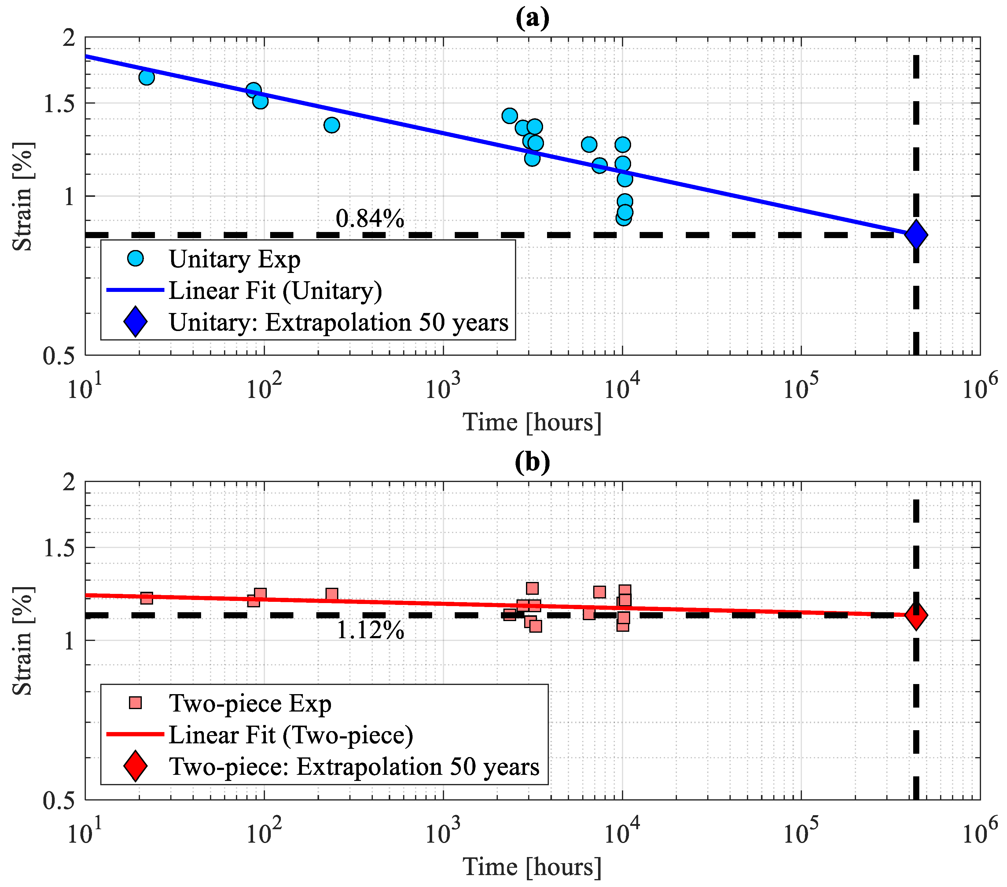
Under the influence of constant diametric deflection and sulfuric acid, the maximum strain for unitary and two-piece rings reduced to about 1.31% and 1.17%, respectively, after 1000 h. Hence, according to these results, a deformation capacity reduction of about 22.8% and 7.2% less than the short-term deformation of dry rings was reached for unitary and two-piece rings, respectively, after 1000 h. The long-term results of the strain corrosion test are illustrated in Figure 4a,b on a logarithmic scale, depicting the failure strain versus time data for the unitary and two-piece pipe, respectively. The regression fit reveals a failure strain of 0.84% at 50 years (438,000 h). In contrast, the two-piece GFRP pipe displays a notably higher failure strain of 1.12% under the same conditions, as shown in Figure 4a, signifying its superior resilience when exposed to prolonged periods of sulfuric acid. The expected failure times are equally distributed with four failures before 1000 h, six failures in between 1000 and 6000 h, and eight failures after more than 6000 h. There were 5–6 samples that did not fail even after exposure for 10,000 h, and these samples were considered failed as per the guidelines in ISO 10952 [15]. The bottom section of the pipe breakage was observed for both unitary and two-piece rings. A common form of damage is the initiation and spread of cracks along the interface between the matrix and fibers. This occurrence results from the combined impact of stress and exposure to a corrosive atmosphere, causing the deterioration of the resin matrix and subsequent weakening of the composite structure. Moreover, delamination, characterized by the separation of layers within the pipe’s wall, can manifest, particularly in regions of stress concentration.
The TGJ of the two-piece pipe remained intact even during failure. To analyze the experimental strain corrosion data, a regression analysis was performed as per the recommendation given in ISO 10928:2016 [20]. Such an extrapolation typically extends the trend from data obtained over 10,000 h to estimate stress and/or strain after 50 years, which is the maximum extrapolation time. The independent variable is the logarithmic of time to failure, whereas the dependent variable is the anticipated value (stress or strain). During the regression analysis, a logarithmic linear curve was fitted to the strain vs. time-to-failure data. The coefficient of log ( t ) represents the rate of degradation owing to chemical exposure. A larger absolute value for this coefficient indicates more deterioration. For unitary rings, the following mathematical Equations (1) and (2) between the strain ( ϵ u ) and time to failure (in hours) was obtained.
ϵ u = 0.0728   log ( t ) +   0.3373
Similarly, for the two-piece pipe, the following mathematical Equation (6) between the strain ( ϵ t p ) and time to failure (in hours) was obtained.
ϵ t p = 0.0081   log t +   0.0937
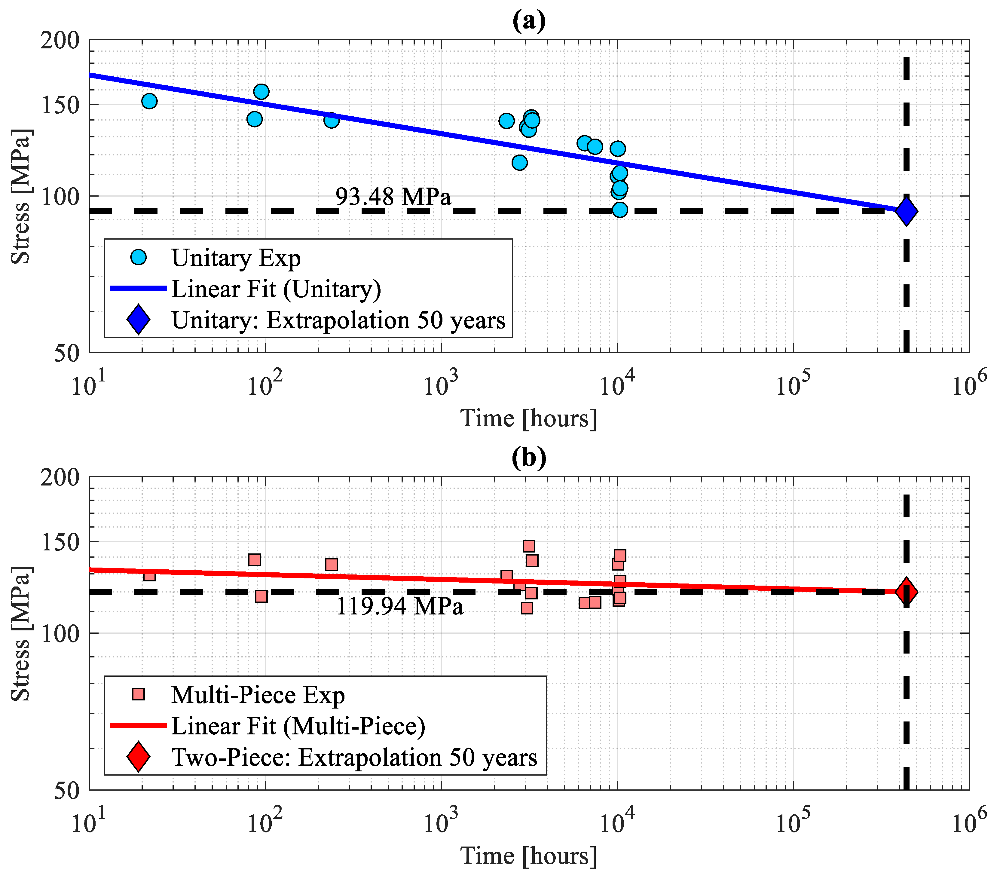
Furthermore, the long-term bending stress was assessed, with the unitary pipe reaching 93.48 MPa at the 50-year mark. In contrast, the two-piece GFRP pipe exhibited a significantly higher long-term bending stress of 119.94 MPa at the 50-year mark, as indicated in Figure 5a, b. This outcome indicates a greater structural integrity and load-carrying capacity of the two-piece pipe over extended timeframes. For unitary rings, the following mathematical Equations (3) and (4) between the long-term bending stress ( σ s ) and time to failure (in hours) was obtained.
σ s = 0.0564   log ( t ) +   2.2890
Similarly, for the two-piece pipe, the following mathematical Equation (8) between the long-term bending stress ( σ m ) and time to failure (in hours) was obtained.
σ m = 0.0092   log ( t ) +   2.1308
In our previous study, it was demonstrated that the stiffness of the pipe with any shape and size increases with the introduction of TGJ on the pipe body [21]. In Figure 4 and Figure 5, it is noticeable that the graph depicting the unitary ring undergoes a sharp decline over a prolonged period. This drop might be attributed to the presence of the uniform L4 layer. This layer, comprising blended sand, imparts greater flexibility but reduces stress resistance in the GFRP. Consequently, an inconsistency becomes apparent in the graph over an extended timeframe. Conversely, a diminished decline in stress and strain is observed in a pipe subjected to prolonged deflection in the case of a two-piece pipe ring. The improved TGJ of the two-piece facilitates stress distribution in areas where the pipe requires more load for deflection. This mechanical response is a result of the heightened load-carrying capacity of the pipe. Further support for this claim comes from the results of the apparent hoop tensile strength test, revealing that two-piece rings exhibit greater resistance to breakage compared to unitary rings after exposure to sulfuric acid.
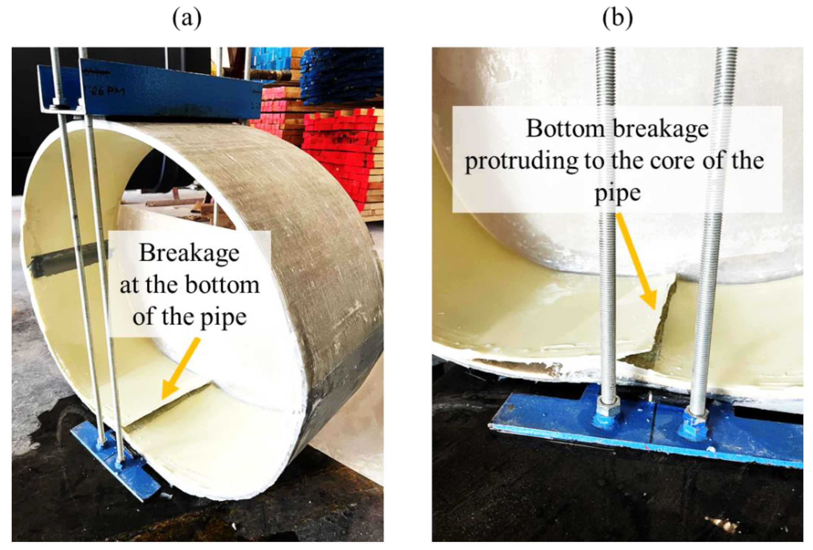
When sulfuric acid comes into contact with the inner surface of the pipe, it directly impacts both the resin matrix and the fiber reinforcement. While isophthalic resin can aid in resisting the hydrolysis of the polymer matrix, the combination of deflection-induced mechanical stress and chemical attack results in material deterioration. This occurs through the breakdown of chemical bonds due to the combined effects of mechanical stress and acid exposure, ultimately weakening the material. During the initial period of 0–1000 h, sulfuric acid initiates its attack on the inner surface of the GFRP samples, particularly focusing on areas of stress concentration. Due to chemical attacks, the resin matrix gradually softens, leading to the formation of microcracks at the interface between the resin matrix and the fibers. As the test progresses to 5000–10,000 h, the extensive chemical attack along with mechanical stress causes the development of larger cracks visible on both the inner and outer surfaces of the pipe. These cracks penetrate through the thickness of the pipe wall, resulting in a decrease in wall thickness due to erosion and material loss. Instances of both top and bottom failures in our test rings were observed, as shown in Figure 6a,b. Moisture absorption by the sandwich GFRP pipe, along with exposure to chemicals, can result in changes to material properties, potentially leading to stress cracking or structural weakening over time. The bending of the rings has caused localized stress concentrations, particularly in regions with abrupt geometric changes, thereby increasing the impact of chemical exposure and facilitating the initiation of cracks. For two-piece rings, no cracks were observed on the longitudinal joints. The tongue section, which is replacing the sand-based material, is manufactured exclusively from unidirectional fibers, making it more resilient in comparison to the pipe wall. This change in the pipe body between unitary and two-piece rings is indicated by the discrepancy in stress distribution which is more evidently seen in unitary than in two-piece rings which has led to an increased stress concentration at both the top and bottom, rendering them more prone to failure [22]. Sulfuric acid, being a potent oxidizing agent, can prompt the dissolution and expansion of the resin matrix within the pipe, therefore compromising its structural integrity, resulting in a decrease in mechanical strength, and potentially giving rise to microcracks in the resin. The corrosive properties of sulfuric acid, in conjunction with the hand layup manufacturing technique employed, may have played a role in degrading the inner corrosion barrier layer of the pipes. Sulfuric acid has the capacity to interact with the glass fibers in the GFRP, inducing a disintegration of the fibers, which in turn reduces the material’s structural integrity to endure mechanical stress. Since the resin used is an isophthalic chemical resistant resin, the effect of the exposure to sulfuric acid will be smaller. Over time, the cumulative corrosive effects of sulfuric acid can result in a gradual decline in the pipe’s chemical resilience and mechanical properties. As the material decreases in its mechanical strength and stiffness, the cracking under stress increases, which will result in less strain to develop cracks over time. Given that these pipes were designed with an inner layer serving as a corrosion barrier, any breach or weakening of this layer, especially at the bottom, could expose the underlying layers to aggressive corrosion. Consequently, this would compromise the overall structural integrity of the pipes in this specific region.
The apparent hoop tensile test data for rings before and after exposure to H2SO4 are presented in Figure 7. The unitary dry ring is indicated as Unitary: Dry followed by the two-piece rings with joint locations at 12 o’clock and 6 o’clock positions as TP1: Dry and joint locations at 3 o’clock 9 o’clock position as TP2: Dry. The dry rings data are shown with solid lines. The maximum load attained by TP1: Dry and TP2: Dry is 49.50 kN (stress value of 87.96 MPa) and 48.61 kN (stress value of 86.38 MPa) respectively, whereas the Unitary: Dry attained a maximum load of 46.76 kN (stress value of 83.09 MPa). Although there is not much difference shown in the apparent hoop strength values of unitary and two-piece rings, it is to be noted that the advantage of having stronger TGJ is indicated in the dry ring testing unilateral compression. The two-piece rings indicate a higher compressive strength and a higher load carrying capacity than the unitary ring.
The apparent hoop rings tested after exposure for 10,000 h showed a decrease in the tensile strength. In Figure 7, the two-piece ring after exposure is indicated as TP1: Exposed and TP2: Exposed for joint locations at 12 o’clock and 6 o’clock positions and 3 o’clock and 9 o’clock position, respectively. The unitary ring is indicated as Unitary: Exposed.
Notably, TP1: Exposed exhibits the highest tensile strength, measuring a load value of 41.41 kN (stress value of 73.58 MPa), followed by TP2: Exposed, which attained a load value of 39.94 kN (stress value of 70.97 MPa). In contrast, Unitary: Exposed shows a lower tensile strength with a load value of 36.00 kN (stress value of 63.97 MPa), as shown in Figure 7. In contrast to the dry rings, exposed rings demonstrated that the apparent hoop strength is improved by 10% and 20% for TP1 and TP2, respectively, when compared to the unitary rings.

4. Materials and Manufacturing

The hand layup method, which was used to make the GFRP pipes, has the benefit of creating a wide range of shapes and sizes without any machinery or specialized equipment [
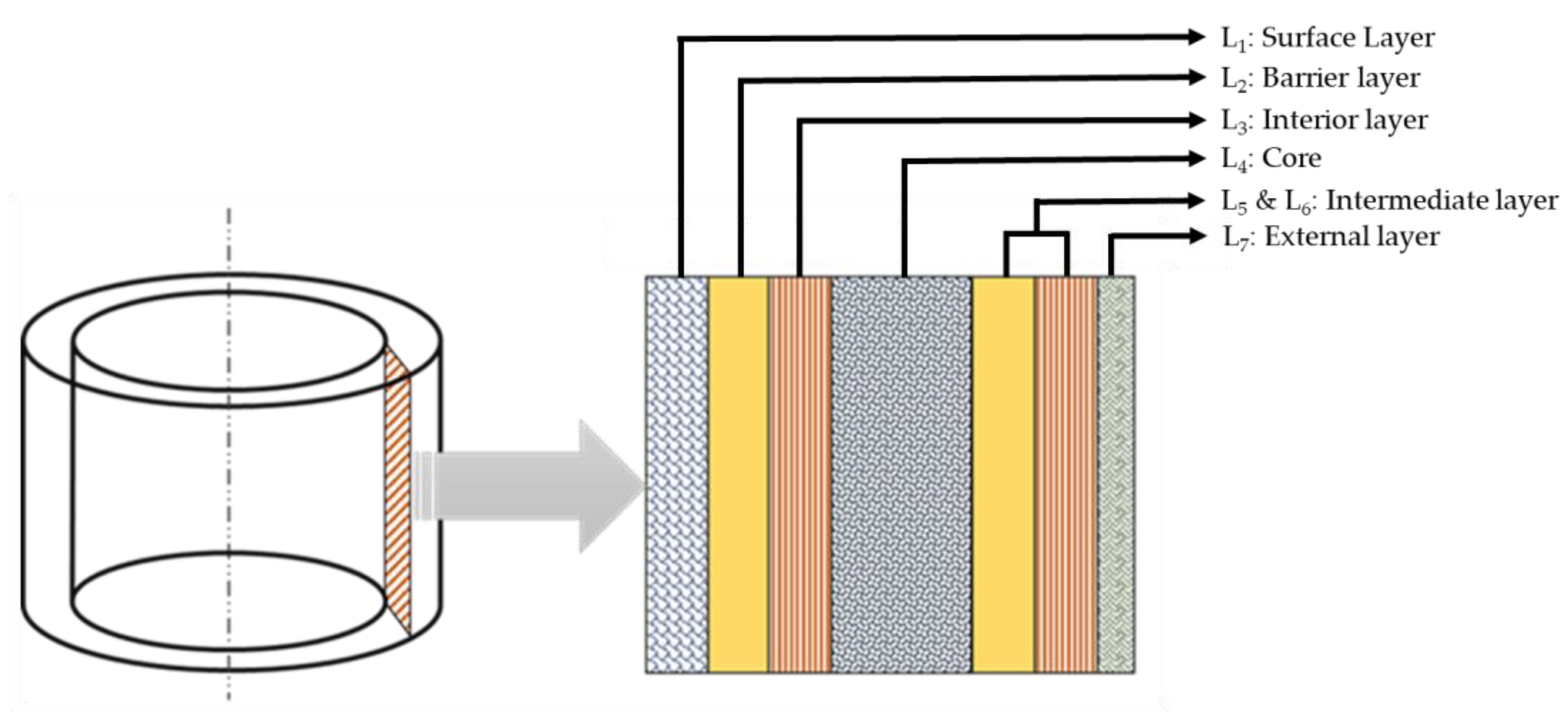
18,23]. These pipes were carefully designed for sewage applications with an inner layer that served as a protective barrier against corrosion and was composed of a surface tissue and chopped strand mat impregnated with isophthalic resin. The core of the sandwich pipe consisted of a blended sand infused with dicyclopentadiene (DCPD) resin. The outer layer was constructed from unidirectional fabric and chopped strand mat, both impregnated with an isophthalic resin.
The function and material of each layer are presented in Table 3, and the arrangement of the layers is shown in Figure 8.
The manufacturing process involved the pipes being made in two sections. A TGJ was adopted to join the two segments [24,25]. The assembling of a two-piece pipe involved the procedure of the crown (top section) being lowered down and joined into the invert (bottom section) of the pipe. In two-piece pipes, joint areas are prone to cracking, delamination, and damage that may lead to a reduction in the mechanical performance of these pipes. For this purpose, the tongue that replaced the weaker core material was fabricated solely using unidirectional fibers, thus making it more resilient compared to the pipe wall layup [21]. An adhesive resin fiber (ARF) mix [26] that was developed in our previous work [21,27] was used for joining the two segments. The ARF mix incorporated repurposed glass fibers ranging in length from 50 to 100 microns with a diameter of approximately 10 microns. Improving fiber wettability was accomplished by initially creating a consistent resin–fiber (RF) mix, combining milled fiber and isophthalic resin at a ratio of 4:1. Subsequently, Crestabond M1-20 structural adhesive was introduced to form the adhesive–resin–fiber (ARF) mix. Notably, the actual fiber volume fractions in the ARF mix constituted only one-fifth of the volume fraction in the RF mix. For instance, an ARF sample comprising 15% RF mix and 85% adhesive contains only 3% milled fiber. The curing time for this mixture was 20–25 min at 25 (±2) °C, and the manufacturing process is depicted in Figure 9. Prior to inserting the crown in the invert, the 65% ARF mix was applied to the TGJ section on the segments (Figure 9d). Immediately following the application of the ARF mix, both segments were glued together and cured for a period of at least three hours. This approach, utilizing short fibers derived from grinding and milling fiberglass waste generated during the pipe lamination process, minimizes material wastage, and promotes sustainable practices in utilizing fiberglass waste.
Incorporating milled fiber into the adhesive significantly enhances the flexural modulus and strength of the adhesive [27]. The optimal performance, in terms of modulus and peak strength, is observed in rings with an ARF composition of 65%. The SEM images depicted in Figure 10 illustrate the fractured surface of the VRF = 65% composite. A clear depiction in Figure 10a shows the surface of the fiber-reinforced adhesive matrix. This distribution appears to be uneven, with clusters of fibers irregularly dispersed within the adhesive–resin matrix. Upon closer inspection of the fractured surface, a residue of broken fibers and adhesive matrix is visible in Figure 10d, indicating a potential brittle fracture at the interface. Furthermore, the smooth cross-section of the fractured fibers, as displayed in Figure 10b, further suggests the characteristics of a brittle fracture. Detailed scrutiny of the fiber–matrix interface unveils a robust attachment of the adhesive–resin matrix to the glass fiber surface. Notably, the lateral surfaces of the fractured glass fibers are entirely covered by the adhesive matrix. This observation suggests that an optimal surface tension between the glass fibers and adhesive facilitates fiber wetting, consequently fostering strong interfacial bonding. Such robust interfacial bonding plays a pivotal role in fortifying the glass fiber composites. Additionally, the fracture surface exhibits several larger-sized pores that are occasionally introduced by the glass fibers [27].
The lateral surfaces of the short glass fibers are fully coated with the matrix. This observation suggests that the appropriate surface tension between the glass fibers and adhesive results in effective wetting of the fibers, leading to a strong interfacial bond. This robust interfacial bonding, in turn, contributes to the reinforcement of glass fiber composites. In the next section, the experimental methods used to evaluate the mechanical integrity and chemical resilience of the pipes are presented.
Table 3. Constituents of the pipe layers [27].
No.PurposeMaterial
L1: Surface LayerThis assures a smooth surface resistant to wastewater and rainwater.Resin reinforced with a surface tissue in type C glass
L2: Barrier layerThis contributes to both the structural aspect and the chemical resistance of the pipes.Chopped strand mat (CSM) impregnated with resin
L3: Interior layerThis contributes to both the structural aspect and the chemical resistance of the pipes.A layer of CSM and unidirectional mats (UDMs) or bi-directional mats (BDMs) impregnated with resin.
L4: CoreThe core layer contributes to the structural aspect of the pipe, mainly the pipe stiffness.A mixture of blended sand, calcium carbonate, and resin
L5 and L6: Intermediate layerThis contributes to the structural aspect of the pipe.Consists of glass fibers (CSM and UDM or BDM) impregnated with resin
L7: External layerThis layer contributes to the shear bond between the exterior of the pipe and the annular grout.Consists mainly of silica sand and resin

5. Methodology

5.1. Uniaxial Lateral Compression

To conduct the strain corrosion test, it is essential to determine the failure strain of dry composite pipes under lateral compression prior to chemical exposure. For this purpose, circular rings with a length (L) of 300 mm (+/−10 mm) were cut from a GFRP sandwich pipe. Special care was taken to avoid damaging the fibers at the open ends of the rings. The ring specifications include an internal diameter d i = 810 mm with a wall thickness t m = 12 mm (+/−2 mm) and length L = 300 mm (+/−10 mm). A uniaxial compressive load was applied to the rings using a universal testing machine in accordance with ISO 10952 [15]. The experimental setup, illustrated in Figure 11, includes both loaded unitary and two-piece rings. At the start, the rings are pre-loaded to maintain alignment between the top and bottom plates. The top plate is then lowered at a constant loading speed of 5 mm/min, and the load displacement data are recorded until fracture.

5.2. Strain Corrosion Test for Unitary and Two-Piece Rings

The strain corrosion method is useful for predicting the effect of a chemical environment on the interior of a GFRP pipe after a specified exposure time. Firstly, pipe rings are deflected (lateral compressive strain), and then the lower half is filled with a corrosive test liquid (25% sulfuric acid (H2SO4)) as per ISO 10952 [15]. The diametrically deflected condition is maintained throughout the test to accelerate the effect of chemicals. Using new test pieces each time, the test is performed at multiple strain levels, and the duration to failure is noted for each strain level. Any ring that seeps the test liquid through the pipe’s inner layer is deemed unsuccessful. The strain value for a given service duration is computed and extrapolated using the strain versus time-to-failure data. As per ISO 10952 standard, a minimum of 18 data points should be considered for regression analysis, and at least one of these rings should fail after 10,000 h [15]. Therefore, 18 rings of unitary and two-piece circular GFRP pipes were manufactured from the same mold by trained laminators with an internal diameter d i = 810 mm with a wall thickness t m = 12 mm (+/−2 mm) and length L = 300 mm (+/−10 mm). The dimensional analysis and Barcol hardness inspection were carried out for all rings to ensure that the quality was maintained. Special care was taken to avoid damaging the fibers at the open ends of the rings. On the interior of the test piece, two straight lines that were diametrically opposed were drawn along the length of the pipe. The wall thickness was measured at six equally spaced points along these lines, and a mean value of these measurements was taken as t m . In the unitary case, the lowest thickness point was kept at the top and the diametrically opposite line kept at the bottom while deflecting the pipe. For two-piece rings, the joint sections were oriented to the left and right (3 o’ clock and 9 o’ clock) as shown in Figure 12c. The inner diameter d i of the test ring was measured by means of a measuring tape. The mean diameter of test piece was calculated as d m = d i + t m . The deflection level should be planned such that the expected failure times are equally distributed, with a minimum of 4 failures before 1000 h, 3 failures after 1000 and before 6000 h, and 3 failures after more than 6000 h. After inserting the pipe into the test apparatus, the apparatus was compressed to deflect the test piece while maintaining the apparatus’s top and bottom plate as parallel as feasible. The equipment was secured by locking the metal bolts, and the setup was removed from the testing machine once the required deflection was obtained. The time was then recorded. The inner diameter of the deflected ring d i was measured, and δ was average vertical deflection. The initial linear strain level was calculated using Equation (5) which included compensation for increased horizontal diameter with increasing deflection [15].
ϵ 0 = 428   t δ d m + δ 2 2
The corrosive fluid was introduced within 2 h after applying the desired deflection. For this purpose, chemically inert dams using a flexible sealant were installed on both ends of the pipe so that only the inside surface of the test piece was exposed to the corrosive fluid solution. Due to the flexibility of the sealant, these dams did not add any structural support to the test piece. The corrosive fluid was 25% sulfuric acid (H2SO4) as per ISO 10952 [15] and ASTM D3681 [13] which was filled in between the dams to a depth of 25–50 mm for the unitary rings, and for the two-piece rings, it was introduced for a depth of 100 mm above the longitudinal joint, as shown in Figure 12, respectively. This was recorded as zero time, and periodically, checks were performed to see the possible leak failures. Test pieces that did not fail after more than 10,000 h were included as failures to establish regression lines. The results of at least 10,000 h of data were used to establish a failure strain %, and the long-term resistance of the pipe to the test solution was obtained via an extrapolation of the curve to 50 years of a log–log linear regression line for the initial strain level versus time. In order to determine the long-term bending strength in the hoop direction using the data obtained in the strain corrosion test method (ISO 10952) [15], the strain levels, reached by the ring deflection, were converted into bending stress using Equations (6) and (7) in accordance to ONORM B5163 [14], as shown below.
σ c i r c = 6 F m a x   d m 2 1 π L t m 2 α k i
α k i = 3 d i + 5 t m 3 d i + 3 t m
where σ c i r c is the long-term ring bending fracture stress, Fmax is the initial force applied, and α k i is a correction factor. The load Fmax in the equation is measured when the ring is deflected. The load for the calculation of the bending stress is taken immediately after the desired deflection is reached.

5.3. Apparent Hoop Tensile Strength Test for Unitary and Two-Piece Ring

The apparent hoop tensile test was conducted to estimate the tensile strength and elongation characteristics of the GFRP material employed in circular pipes. These data were essential for gaining insights into how the material responds to hoop stress, which is a prevalent stress condition arising from internal pressure within the pipes. The apparent hoop tensile test was carried out following the steps prescribed in ASTM D2290—Procedure A [16]. The test was performed for both unitary and two-piece pipes. Dry rings for both unitary and two-piece rings were tested to measure the tensile strength value prior to the exposure of the rings to a corrosive environment. One specimen of a unitary ring and two specimens of two-piece rings were selected from the strain corrosion test that had crossed 10,000 h, and a comparison study was made after exposure to understand the strength difference between unitary and two-piece pipes. Circular rings have identical internal diameters, wall thickness and widths (w) of 22.86 mm, and a minimum width in the reduced section(s) of 13.97 mm. The number of reduced sections is one or two as per ASTM D2290 [16]. However, for our study, two reduced sections for all rings, to obtain a more accurate assessment of the tensile behavior, were adopted. The reduced sections were located 180° apart from each other, as shown in Figure 13. For the two-piece pipe, the reduced section was placed on the pipe wall for one ring (longitudinal joint at 12 o’clock and 6 o’ clock), as shown in Figure 13d. For the second ring (longitudinal joint at 3 o’clock and 9 o’clock) the reduced section was created at the TGJ joint, as shown in Figure 13e, to study the effect of chemical exposure on the joints that were bonded using the ARF mix. The ring was mounted on the test fixture and secured tightly with the reduced areas centered away from the split disk. The tensile load was then applied, pulling the sample apart at a constant speed of 10 mm/min as per ASTM D2290 [16].
The load carried by the ring was recorded, and the apparent tensile stress in the reduced section of the ring was calculated using Equation (8).
σ a = P 2 w t

6. Conclusions

In practical scenarios, the findings from the current study bear significant implications for industries requiring pipes to endure extended exposure to corrosive chemical environments while maintaining structural integrity over prolonged periods, particularly in the trenchless sector. The key performance, as evidenced by the enhanced failure strain and long-term bending stress in two-piece GFRP pipes, suggests their potential as a more reliable option for infrastructure. The key findings are listed below.
  • The transportation cost analysis supports the adoption of the two-piece circular pipe configuration for its enhanced efficiency, capacity, and a 40% reduction in both carbon emissions and fuel consumption. These factors contribute not only to cost-effectiveness but also to more environmentally sustainable transportation.
  • The uniaxial lateral compression test showed a small reduction of ~4% in deformation at break for two-piece rings compared to the unitary case. The short-term strain was 1.697% for the unitary ring and 1.2613% for the two-piece ring. This implies that going from a unitary pipe to a two-piece pipe causes the pipe to become more brittle.
  • The extrapolation of test data showed that the unitary pipe is expected to exhibit a 0.84% failure strain after 50 years (438,000 h). In contrast, the two-piece GFRP pipe demonstrated a ~33% higher failure strain of 1.12% under identical conditions. Similarly, for long-term bending stress, the unitary pipe showed an extrapolated stress value of 93.48 MPa at the 50-year mark, whereas the two-piece GFRP pipe displayed a significantly superior long-term bending stress of 119.94 MPa.
  • Dry condition testing showed that a two-piece sample had an average peak load of 49.05 kN, whereas the unitary pipe had a considerably lower peak load of 46.76 kN.
  • GFRP pipes exhibited a decreased peak load following exposure to H2SO4 in both unitary and two-piece cases. It is worth noting that the average peak load for the two-piece after exposure was 40.67 kN, which is 10% greater than the unitary case’s peak load of 36.00 kN.
In summary, this study presents a comprehensive evaluation of two-piece GFRP pipes for applications in corrosive environments and trenchless scenarios. The findings provide novel insights into the enhanced durability of two-piece GFRP pipes, specifically highlighting their ability to withstand prolonged exposure to corrosive chemicals. Furthermore, the transportation cost analysis adds a unique perspective by demonstrating the economic and environmental benefits of adopting two-piece circular pipes, thereby promoting sustainable long-distance transportation solutions. Engineers are recommended to contemplate employing two-piece pipe configurations, particularly in scenarios where pipes are to be installed in fewer access points or subjected to prolonged exposure to mechanical stress or a corrosive environment.

Author Contributions

Conceptualization, D.C. and P.U.; methodology, D.C. and P.U.; software, P.U.; validation, D.C. and P.U.; formal analysis, S.R.; investigation, D.C., S.R. and P.U.; resources, D.C.; data curation, D.C. and S.R.; writing—original draft preparation, D.C. and S.R.; writing—review and editing, P.U.; visualization, D.C.; supervision, P.U.; project administration, D.C. and P.U.; funding acquisition, D.C. All authors have read and agreed to the published version of the manuscript.

Funding

This research received no external funding.

Data Availability Statement

The data presented in this study are available on request from the corresponding author.

Conflicts of Interest

The authors declare no conflict of interest.

References

  1. Ellyin, F.; Rohrbacher, C. Effects of Aqueous Environment and Temperature on Glass-Fiber Epoxy Resin Composites. J. Reinf. Plast. Compos. 2000, 19, 1405–1427. [Google Scholar] [CrossRef]
  2. Guedes, R.M.; Sá, A.; Faria, H. On the Prediction of Long-Term Creep-Failure of GRP Pipes in Aqueous Environment. Polym. Compos. 2010, 31, 1047–1056. [Google Scholar] [CrossRef]
  3. Rafiee, R. On the mechanical performance of glass-fibre-reinforced thermosetting-resin pipes: A review. Compos. Struct. 2016, 143, 151–164. [Google Scholar] [CrossRef]
  4. Hakeem, I.Y.; Özkılıç, Y.O.; Bahrami, A.; Aksoylu, C.; Madenci, E.; Asyraf, M.R.M.; Beskopylny, A.N.; Stel’makh, S.A.; Shcherban, E.M.; Fayed, S. Crashworthiness Performance of Filament Wound GFRP Composite Pipes Depending on Winding Angle and Number of Layers. Case Stud. Constr. Mater. 2024, 20, e02683. [Google Scholar] [CrossRef]
  5. Strohmer, F. Online Monitoring of Glassfiber Reinforced Plastic Pipes. In Proceedings of the National Forum of Maintenance of Slovakia 2015, NÁRODNÉ FÓRUM ÚDRŽBY 2015, VYSOKÉ TATRY, Strbske Pleso, Slovakia, 2–3 June 2015. [Google Scholar]
  6. Jones, R.M. Mechanics of Composite Materials; CRC Press: Boca Raton, FL, USA, 2018. [Google Scholar]
  7. Madenci, E.; Özkılıç, Y.O.; Aksoylu, C.; Asyraf, M.R.M.; Syamsir, A.; Supian, A.B.M.; Mamaev, N. Buckling Analysis of CNT-Reinforced Polymer Composite Beam Using Experimental and Analytical Methods. Materials 2023, 16, 614. [Google Scholar] [CrossRef] [PubMed]
  8. Özkılıç, Y.O.; Gemi, L.; Madenci, E.; Aksoylu, C. Effects of Stirrup Spacing on Shear Performance of Hybrid Composite Beams Produced by Pultruded GFRP Profile Infilled with Reinforced Concrete. Archiv. Civ. Mech. Eng. 2022, 23, 36. [Google Scholar] [CrossRef]
  9. Uomoto, T. Durability Design of GFRP Rods for Concrete Reinforcement. In Proceedings of the Sixth International Symposium on FRP Reinforcement for Concrete Structures (FRPRCS-6), Singapore, 8–10 July 2003; pp. 37–50. [Google Scholar]
  10. Karbhari, V.M.; Chin, J.W.; Hunston, D.; Benmokrane, B.; Juska, T.; Morgan, R.; Lesko, J.J.; Sorathia, U.; Reynaud, D. Durability Gap Analysis for Fiber–Reinforced Polymer Composites in Civil Infrastructure. ASCE J. Compos. Constr. 2003, 7, 238–247. [Google Scholar] [CrossRef]
  11. Public Works Standards, Inc. California Greenbook: Standard Specifications for Public Works Construction; BNI Publications: Vista, CA, USA, 2021. [Google Scholar]
  12. AS 3572.2-2002; Australian Standard. Plastics-Glass Filament Reinforced Plastics (GRP)-Methods of Test-Determination of Chemical Resistance of Glass Reinforced Plastics. Standards Australia: Sydney, Australia, 2002.
  13. ASTM D3681; Standard Test Method for Chemical Resistance of “Fiberglass” (Glass–Fiber–Reinforced Thermosetting-Resin) Pipe in a Deflected Condition. ASTM International: West Conshohocken, PA, USA, 2023.
  14. DIN EN 1401; Rohrleitungssysteme Für Drucklose Abwasserleitungen Und-Kanäle―Nicht-Kreisrunde Rohre, Rohrverbindungen Und Formstücke Aus Glasfaserverstärkten Duroplastischen Kunststoffen (GFK) Auf Der Basis von Ungesättigten Polyesterharzen (UP)―Abmessungen, Anforderungen, Prüfungen Und Verfahren Für Den Nachweis Der Normkonformität. Techstreet LLC: Ann Arbor, MI, USA, 2023.
  15. ISO 10952; Glass-Reinforced Thermosetting Plastics (GRP) Pipes and Fittings—Determination of the Resistance to Chemical Attack for the inside of a Section in a Deflected Condition. International Organization for Standardization: Geneva, Switzerland, 2021.
  16. ASTM D2290; Standard Test Method for Apparent Hoop Tensile Strength of Plastic or Reinforced Plastic Pipe. ASTM International: West Conshohocken, PA, USA, 2019.
  17. Practical Guide For Calculating Greenhouse Gas (Ghg) Emissions; Version: 1 March 2019; Oficina Catalana del Canvi Climatic: Barcelona, Spain, 2019.
  18. WRc WAA 4-34-02, No. 1; Information and Guidance Note No. 4-34-02; WRc Engineering: München, Germany, 1986.
  19. Farshad, M.; Necola, A. Strain Corrosion of Glass Fibre-Reinforced Plastics Pipes. Polym. Test. 2004, 23, 517–521. [Google Scholar] [CrossRef]
  20. ISO 10928:2016; Plastics Piping Systems Glass-Reinforced Thermosetting Plastics (GRP) Pipes and Fittings. Methods for Regression Analysis and Their Use. International Organization for Standardization: Geneva, Switzerland, 2016.
  21. Chelot, D.; Upadhyaya, P. Experimental Study on Multi-Segmented Circular or Non-Circular Pipes to Determine the Pipe Stiffness. Key Eng. Mater. 2022, 934, 171–178. [Google Scholar] [CrossRef]
  22. Zhang, Z. Theoretical Prediction of Cross-Sectional Deformation of Circular Thin-Walled Tube in Large Elastic–Plastic Deformation Stage under Lateral Compression. Thin Walled Struct. 2022, 180, 109957. [Google Scholar] [CrossRef]
  23. Elkington, M.; Bloom, D.; Ward, C.; Chatzimichali, A.; Potter, K. Hand Layup: Understanding the Manual Process. Adv. Manuf. Polym. Compos. Sci. 2015, 1, 138–151. [Google Scholar]
  24. Melogranaa, J.D.; Grenestedt, J.L.; Maroun, W.J. Adhesive Tongue-and-Groove Joints between Thin Carbon Fiber Laminates and Steel. Compos. Part A 2002, 34, 119–124. [Google Scholar] [CrossRef]
  25. Dvorak, G.J.; Zhang, J.; Canyurt, O. Adhesive Tongue-and-Groove Joints for Thickn Composite Laminates. Compos. Sci. Technol. 2001, 61, 1123–1142. [Google Scholar] [CrossRef]
  26. Robert, K.W.; Zimmerly, D. Multi-Piece Pipe Clamp. United. States Patent 4568115, 4 February 1986. [Google Scholar]
  27. Chelot, D.; Tewari, A.; Shanmugam, K.; Upadhyaya, P. Enhanced Strength and Toughness of Repurposed Glass Fiber Reinforced Adhesive Joints for Sewage Applications. J. Adhes. 2023, 100, 556–575. [Google Scholar] [CrossRef]
Figure 1. Unitary pipes configuration for (a) HS1 configuration (b) HS2 configuration, (c) VS configuration. (d) Unitary circular pipe dimensions.
Recycling 09 00028 g001
Figure 2. Top view of the container loading plan for a two-piece pipe.
Recycling 09 00028 g002
Figure 3. Installation of two-piece pipe with smaller access point.
Recycling 09 00028 g003
Figure 4. Graphical representation of failure strain % at 50 year mark. (a) Unitary; (b) two-piece pipe. Black dashed lines indicate the 50-year time marker and the associated predicted strain value.
Recycling 09 00028 g004
Figure 5. Graphical representation of long-term bending stress at 50-year mark. (a) Unitary; (b) two-piece pipe. Black dashed lines indicate the 50-year time marker and the associated predicted stress value.
Recycling 09 00028 g005
Figure 6. (a) Breakage of two-piece rings at the bottom; (b) zoomed-in view to show the propagation.
Recycling 09 00028 g006
Figure 7. Load displacement curves comparing unitary and two-piece pipe during apparent hoop tensile strength test.
Recycling 09 00028 g007
Figure 8. Constitution of the wall of the GFRP sandwich pipe.
Recycling 09 00028 g008
Figure 9. Schematic of manufacturing multi-piece pipe. (a) Milled fiber resin mix. (b) ARF 65% mix. (c) Crown and invert with grooves. (d) Application of ARF mix in the groove. (e) Lowering of crown to create TGJ. (f) Final two-piece pipe with TGJ.
Recycling 09 00028 g009
Figure 10. SEM images of ARF mix specimens highlighting (a) surface of fiber-reinforced adhesive matrix; (b) intact fiber inside the voids/pores [27]; (c) fibers with random non-uniform orientations; (d) broken fibers surrounded by the adhesive and resin [27].
Recycling 09 00028 g010
Figure 11. (a) Uniaxial lateral compression set up; (b) uniaxial lateral compression of unitary ring; (c) uniaxial lateral compression of two-piece ring.
Recycling 09 00028 g011
Figure 12. (a,b) Deflection of two-piece pipe; (c) ongoing strain corrosion test of two-piece pipes.
Recycling 09 00028 g012
Figure 13. (a) Unitary: Exposed ring with the reduced section at pipe wall; (b) TP1: Exposed sample mounted on the test apparatus for apparent hoop tensile strength test; (c) breakage of the ring at the reduced section for Unitary: Exposed specimen; (d) TP1: Exposed specimens showing the breakage of the ring at the reduced section located at pipe wall; (e) TP2: Exposed specimen showing the reduced section at TGJ; (f) breakage of TP2: Exposed specimen at the TGJ.
Recycling 09 00028 g013
Table 1. Summary of transportation cost analysis for unitary pipes.
Container Loading OrientationLoaded Length/Container (m)Transportation Cost (USD)CO2 Emissions (kg)
HS1***
HS1212.21,300,000146.47
HS29.761,625,000183.09
VS14.641,085,500122.06
* Not possible because of constraints on pipe dimensions or risk of pipe damage.
Table 2. Summary of transportation cost analysis for unitary and two-piece pipe for VS.
UnitaryTwo-Piece
Loaded Length/Container (m)Transportation Cost
(USD)
CO2
Emission
(kg)
Loaded Length/Container (m)Transportation
Cost
(USD)
CO2
Emission (kg)
14.641,085,500122.0624.40650,00073.23
Disclaimer/Publisher’s Note: The statements, opinions and data contained in all publications are solely those of the individual author(s) and contributor(s) and not of MDPI and/or the editor(s). MDPI and/or the editor(s) disclaim responsibility for any injury to people or property resulting from any ideas, methods, instructions or products referred to in the content.

