Article

Robust 3D Object Model Reconstruction and Matching for Complex Automated Deburring Operations

Smart and Autonomous Systems Unit, IK4-Tekniker, C/Iñaki Goenaga 5, Eibar 20600, Spain
*
Author to whom correspondence should be addressed.
J. Imaging 2016, 2(1), 8; https://doi.org/10.3390/jimaging2010008
Submission received: 2 December 2015 / Revised: 1 February 2016 / Accepted: 4 February 2016 / Published: 16 February 2016

Abstract

:
The deburring processes of parts with complex geometries usually present many challenges to be automated. This paper outlines the machine vision techniques involved in the design and set up of an automated adaptive cognitive robotic system for laser deburring of metal casting complex 3D high quality parts. To carry out deburring process operations of the parts autonomously, 3D machine vision techniques have been used for different purposes, explained in this paper. These machine vision algorithms used along with industrial robots and a high tech laser head, make a fully automated deburring process possible. This setup could potentially be applied to medium sized parts of different light casting alloys (Mg, AlZn, etc.).

Graphical Abstract

1. Introduction

In die casting processes, ferrous and non-ferrous metallic alloys are taken to the liquid state, and products receive their final form by means of the injection and further solidification of these cast alloys in a mold. Casting of metals is one of the industrial activities with more tradition in Europe. The European industry is the second largest in the world for ferrous castings—far behind China—and the largest for forgings and non-ferrous castings. According to the European Foundry Association (CAEF), the most important market segments for castings in European Union are the automotive industry (50% of all castings), the engineering industry (30%), the construction industry (10%) and others, such as the aeronautics and electronics industry (10%). While the majority of volume falls upon the ferrous alloys family, the growing trend in the automotive sector towards lighter vehicles has resulted in an increased interest in light metals, particularly aluminum and magnesium. Regarding aluminum and its alloys, it has imposed itself as material of choice in key engine components such as cylinder heads, blocks, and pistons and even high-end car structures, due mainly to its excellent specific weight and corrosion resistance. Other sectors where aluminum has widespread use are aerospace, naval, railroad, furniture, and electric appliances.
On the other hand, the pressure from emerging economies has resulted in a general reduction in the market share at European level, especially in low/medium added value components. As a response to this phenomenon, and in order to maintain competitiveness, the sector has responded with an upgrade and optimization of its technologies, with the growing automation of the casting process one of its main consequences, taking machine vision as a fundamental technique for automated object recognition, grasping, and processing.
Among other operations, the deburring process is one of the most important finishing operations which are carried out during the manufacture of castings parts. The most common automated systems used for that purposes are based on cutting presses and robotized abrasive tools which are not flexible or adaptable to complex specific parts or to the production of short part series, which is a common problem for SMEs.
Cutting press machines are responsible for cutting the sharp edges or burrs generated on the component, or even thicker parts as sprues and runners, which are formed during the injection process.
Sometimes, given the complexity of the piece, the thickness, and type of material, the cutting is imprecise and generates unwanted geometric deviations on the parts. As a result, for certain types of pieces, it is necessary to add new operations, including inspection, review, and manual deburring and sanding with abrasive tools, which implies extra costs in the production process and a slower production. Other aspects that make the deburring stage more costly are the need to manufacture cutting dies and tools for each part geometry, as well as the wear that these cutting tools suffer after several production cycles, accelerated when burrs are thicker as a consequence of the progressive wear of the injection mold.
Nowadays, the cutting die cost is amortized when a high volume of parts is produced. However, a current trend in new markets is the production of short series. Therefore, new alternatives, capable of covering this deburring operation without cutting dies, open a new field of operation until now previously unfeasible.
Although deburring robots are well established in industry, most of them are based on mechanical tools and use fixed trajectories and force control, thus, the robot in these cases usually perform the same trajectory, applying mechanical abrasion with an identical force, always on the same points of the part, irrespective of the existence of burrs or not, eroding the part when no burrs are present. This existing approach implies a great disadvantage when processing high quality products, where finish quality is fundamental.
To overcome these limitations in the actual deburring techniques, and make this operation more flexible and adaptable to complex pars and small series, machine vision techniques can be applied as fundamental tools for the principal task of 3D part reconstruction and burr detection.
This paper is organized as follows: The following section reviews the state of the art in both deburring and machine vision applied to object recognition and inspection in robotics. Section 3 presents the problem of burr detection in complex parts carried out in this research, and finally, Section 4 and Section 5 present the results obtained and future work in this field.

2. State of the Art and Previous Related Works

In many cases, deburring processes are not automated, depending on manual operation, however, the evolution in the manufacturing processes demands a sustancial improvement in these techniques [1].
The actual deburring techniques are not easily applicable to many new production lines, and a set of alternative methods are being applied, such as electrochemical or thermal deburring for high production volumes [2]. The limitations present in these processes have driven a new laser-based cutting approach for deburring, already tested in different materials: different types of steel [3,4,5,6,7,8], aluminum based alloys [9,10], titanium based alloys [11,12,13], copper [14,15], and even ceramics [16,17], glass [18,19], polymers [16,17], or composites [20,21]. These new approaches are generally applied in a fixed setup, requiring important changes in the deburring station to adapt the process to new geometries. The research presented in this paper presents a flexible setup based on machine vision to apply laser deburring to complex parts in a flexible way.
Machine vision is applied all over the process to solve two principal tasks: pose estimation and 3D reconstruction for burr detection.
Pose estimation problems appear continuously in many robotic environments. Research in robotics is focused on trying to solve problems with uncertainties, and one of these fundamental problems is manipulating objects in a 3D space. This problem, in its generic form, has been an active field of research in recent years [22]. In [23], they use color concurrence histograms and geometric modeling to identify objects for manipulation and grasping, using a classical learning framework for decision making.
Also, in many applications, such as the one proposed in this paper 3D reconstruction of point datasets is of vital importance. Good examples of these techniques applied to reconstruction can be found in [24,25]. In [26], they focus in the real time processing of the 3D point clouds acquired in real time. This is one of the fundamental problems to solve, because the processing of pure 3D point clouds is very computationally intensive.
Along with pose estimation, 3D matching of objects is another fundamental field of research in many applications, such as quality control, or part processing and manufactuning. In this research the very precise matching of the part with its CAD definition turns out to be fundamental for the correct detection of burrs and flaws in the part.
In some applications, CAD models are used to represent the knowledge of the world, giving information of the environment for object recognition and matching [27]. In this application, burr detection will be carried out by comparison of the 3D reconstruction with the STL model of the part.
Other approaches use different techniques for 3D object recognition and pose estimation, for example, in [28], 3D view-based eigen spaces are used, Features histograms are used in [29], and basic research has been carried out using single colored objects in [30] and keypoint features for robotic manipulation are used in [31]. Active appearance models are another approach used in [32].
During the last years, several new interesting research works have contributed to the development of new object matching approaches. In [33] a view-invariant object detection and pose estimation algorithm is proposed, using the object contours as input data. Another interesting work on recognizing objects in point clouds is described in [34]. In this case, a global model description based on oriented point pair features is used to match a model locally using a fast voting scheme.
Many approaches to the object matching and recognition problem are based on keypoints. A study is presented in [35] about the robustness and quality of keypoints to be used in matching problems.
Matching and recognition of objects are strictly related to what is called object retrieval, and studies carried out for this task are also applicable to the previous. In [36], object retrieval is done by using the 2D projections of the 3D object.
Finally, Tombari et al. [37] presents an interesting work, taking advantage of the current RGB-D sensors, with provide shape and texture information. This paper presents a novel descriptor that improves the accuracy obtained with other previous works based on descriptors.

3. Problem Definition

In the process of developing an automatic and robotized deburring station, complex automotive engine aluminum castings have been selected to demonstrate the technology. Initially, a flexible configuration has been considered, so that the deburring detection process is applicable to different parts, having the CAD model as an input.
Attending to this criteria, one complex part has been selected for machine vision algorithm testing, with a volume of 150 mm × 150 mm × 110 mm. Figure 1 presents the CAD representations of them.
Generally, in aluminium casting alloys, the areas where burrs are to be treated usually appear along the closure line of the mold. For reference, Figure 1, 10 different burr areas have been selected, and the thickness of each of them has been measured. The final roughness to be achieved in the parts has been obtained by evaluating the results using current finishing methods. The Ra parameter has been measured, according to standard ISO 4288, wherever possible, in a finished part. As an example, pictures with the burr zones defined by numbers are shown in Figure 2.
Figure 1. CAD representation of the part used for the research.
Jimaging 02 00008 g001
Figure 2. Burr examples in example part.
Jimaging 02 00008 g002
Table 1 summarizes the thickness in the sample part for each particular burr zone. The target surface roughness of 7.5 μm is the required finishing quality for the part, after eliminating the burr by the laser process. This second process is out of the scope of this paper.
Table 1. Burr thickness for the different references.
Zone in Sample PartBurr Thickness (mm)
13
23
31.5
41.4
51.7
60.25
71.6
81.6
91.2
100.9
For each part, the fundamental operations for the process must be carried out using 3D machine vision. These are, burr detection using 3D part reconstruction and matching with CAD model.

4. Methods

The problem proposed, burr detection, consists of three principal steps:
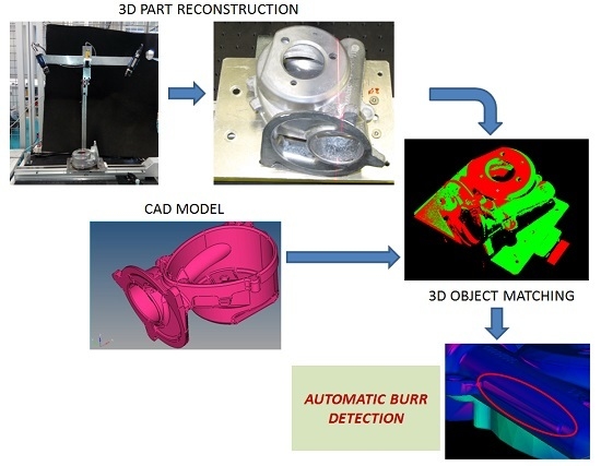
  • 3D reconstruction of the part, using sheet of light techniques and registration methods to obtain a point cloud volume avoiding shadows and occlusions.
  • Point cloud filtering and clustering to obtain a robust model of the part under inspection.
  • Matching with the identified part CAD model, STL file in this case, to obtain volume differences corresponding to burrs.
The following subsections explain the different steps in both problems in more depth.

4.1. 3D Reconstruction and Partial View Registration

The sheet of light setup used for 3D reconstruction is a dual camera system, in a reversed ordinary setup configuration. According to [38], the reversed ordinary setup provides a good height resolution avoiding miss-register problems, provided the α angle is fixed between 15° and 65°. Smaller angles lead to bad sampling conditions, and larger angles lead to occlusions. The height resolution obtained with this setup can be expressed as follows, assuming that the pixels of the sensor are square:
Δ z Δ x s e n s o r sin ( α )
where Δ z is the resolution in Z axis in real world coordinates and Δ x s e n s o r is the increment of pixels in the X axis of the camera sensor.
The dual camera system is mounted in the sense of the relative movement of the part under inspection, so occlusions due to geometry are avoided. Figure 3 shows the real setup and the corresponding schematics. Additionally, for each of the two cameras, calibration has been performed so that the partial point clouds are obtained directly in real world coordinates, in this case, mm, which are the units in the part STL model.
Figure 3. (a) Dual camera laser triangulation system, in reversed ordinary setup; (b) schematics of the setup.
Jimaging 02 00008 g003
The technical specifications of the system are summarized in the following points:
  • Two Dalsa Genie HM1400 matricial cameras, with a 1400 × 1280 pixel sensor, with a pixel size of 7.4 μm, and up to 75 fps. The image output format is GigE Vision.
  • High resolution optics, f 1.4, with a focal length of 16 mm.
  • Lasiris SLH-501L red laser line generator, with a 30° fan angle.
  • Working area of 200 mm in x axis. Y axis obtained by camera triggering.
  • System calibrated in X and Z using 100 × 100 mm squared calibration plate. Optimum height resolution has been found with a value of α = 30°.
  • The relative movement is carried out using a SMC LEFS32S3A linear axis with a 600 mm moving range and a resolution of 0.02 mm, commanded by a SMC LEC SA2-S3 servo motor.
For the registration of both partial reconstructions obtained from the part, key points have been extracted using the scale-invariant feature transform algorithm (SIFT) [39]. Having obtained the key points, the registration is performed in two steps, first using a FANN algorithm [40] for initial registration of clouds, and ICP [41] in a second step to minimize errors, obtaining as a result the affine transformation of the point cloud of the one camera with respect to the other, taking as coordinate reference the first camera in the sense of movement (A in Figure 3b):
H r e g i s t r a t i o n = H i c p H f a n n = [ R i c p R f a n n R i c p t f a n n + t i c p 0 0 0 1 ]
Transforming the second partial point cloud by Equation (2) and adding the points to the first point cloud taken as reference, a first registration step is achieved. This initial step can be seen in Figure 4:
Figure 4. Registration of the two partial point clouds (red and green) obtained.
Jimaging 02 00008 g004

4.2. Point Cloud Preprocessing

After obtaining the registered point cloud, further processing is needed to obtain a suiTable 3D volume to be compared against the STL model of the ideal part. All needed configuration parameters in the different operations have been fixed empirically after performing some tests, and taking into account the characteristics of the initial point clouds in terms of number of points and spatial resolution of 0.25 mm/pix in X axis and 0.5 mm/pix in Y axis. Operations applied on the point cloud with brief description and parameters are listed below in order of application:
  • Outlier removal: Using the euclidean distance as measuring criterium, an outlier in the point cloud is defined as a point whose mean distance to the k nearest neighbours is bigger than D mm, with k = 3 and D = 5.
  • Downsampling using a voxel grid filter: All the points within voxel cubes of d mm of edge, are substituted by a new point, the cube centroid. Voxel cubes containing less than n points are removed from the point point cloud. d = 0.5 mm, n = 5 points.
  • Smoothing of the downsampled pointcloud: For point cloud smoothing the MLS algorithm is used, and fits a planar surface or a higher order polynomial surface to its k nearest points. The surface fitting is a standard weighted least squares parameter estimation of the plane or polynomial surface parameters, respectively. The closest neighbors of P have higher contribution than the other points, which is controlled by the following weighting function with a parameter ⱷ:
    w ( P ) = e ( P P 2 φ 2 )
The point being processed is then projected to the calculated local surface, with a relative ⱷ = 1.0.
Applying these three steps to the initial registration process as explained in Section 4.1, a smoothed model with less noise is obtained, suitable to be used for detecting burrs in the part, by comparing it with the initial CAD model. Figure 5 shows the final model of the reconstructed part.
Figure 5. Final model after outlier removal, downsampling, and smoothing.
Jimaging 02 00008 g005

4.3. Matching with CAD Model and Burr Detection

For burr detection, the point cloud model generated in the previous section is used to carry out a registration with the STL model. The registration operation is based essentially on the same procedure explained in Section 4.1, taking as point clouds to register the generated 3D model from the scanned part, and the STL design model available. Once the complete registration is performed, distance from the scanned part to the nearest model surface is calculated, by establishing a threshold in distance of 0.1 mm. Points whose distances are above this threshold are marked as burr points.
The last step is a 3D clustering of these points, to obtain position and size of the burr that will be oblated by the laser, as illustrated in Figure 6.
Figure 6. Detail of type 2 burr detection, in pink-red color.
Jimaging 02 00008 g006

5. Results

Several experiments have been performed to assess the validation of the proposed process. In the first experiment, 10 parts have been taken directly from the production line are taken through the inspection procedure for burr detection. Not all the parts have all the classified types of burrs as described in Section 3. In these cases no data is provided. When a burr type is present, the left value indicates the thickness measured by the algorithm proposed, and the right value the real thickness of the burr measured manually. All the measurements are in mm. Table 2 shows the results for this test.
Table 2. Burr detection. For each part and burr type, measured burr in mm.
-Burr Type
Part N.12345678910
12.932.72.81.81.8--2.120.50.51.51.61.51.5--0.91
22.92.8--1.41.51.31.422.10.70.7-- 1.11.3--
332.92.92.7--1.81.72.12.2--1.71.71.71.81.71.71.21.2
4--33.11.61.721.92.220.30.4--1.51.61.31.3
52.83-- --2.32.3--1.61.71.61.7--1.11.2
633.13.23.21.61.41.61.62.22.20.70.51.51.51.41.41.61.510.9
72.92.82.62.7--1.51.522.10.50.31.81.8--1.81.711.1
82.92.72.62.621.91.71.822.10.50.51.41.41.71.61.81.60.91
933.1331.721.71.7--0.70.61.61.71.81.9--10.8
10----1.91.81.41.32.32.40.30.41.61.61.61.51.51.51.31.3
Several statistical measurements have been extracted after inspecting 100 different examples for each type of burr. The mean values of real thickness of the burr, mean values of the measured thickness, and the deviations between both values are presented in Table 3.
Table 3. Statistical error measurements.
Burr TypeMean Measured Thickness (mm)Mean Real Thickness (mm)Mean Error (mm)Error Percentage over Real Measurement (%)
12.93−0.13
23300
31.51.6−0.16
41.61.7−0.16
52.02.2−0.29
60.60.8−0.225
71.51.500
81.61.7−0.15
91.31.4−0.17
101100

6. Conclusions and Future Work

Based on the results presented in the previous section, several important conclusions can be extracted about the performance and validity of the solution proposed. The main points to take into account are:
  • The thickness measured in the burrs is always smaller than the real thickness. This is important to avoid an excessive deburring of the part, compromising its mechanical properties.
  • The errors in measurements are proportionally much bigger when the burr size is smaller, however, never bigger than 0.2, an admissible tolerance for general deburring applications.
  • All the burr types defined in the reference part are correctly detected and with measurement errors smaller than 0.2, a tolerance that assesses the validation of this setup for industrial use in automatic deburring stations.
Taking into account the previous points, it can finally be concluded that this research can be directly applicable to industrial automated deburring setups, however several points could be developed further to obtain a more flexible and industrialized system from this initial research station. These developments could be:
  • Obtaining a more compact system, to be able to mount the complete set up as a robot tool.
  • Substitution of the linear axis by a small working area robot. With this new setup, any complex part could be scanned and reconstructed from different and variable angles, avoiding shadows and occlusions. In this case, precise calibration of the working area of the robot would be needed so that precise affine transformations could be done to the obtained partial point clouds, before proceeding to the global registration of them all to obtain the part surface model.

Acknowledgments

This research has been carried out within the scope of the experiment DEBUR—“Automated robotic system for laser deburring of complex 3D shape parts”. DEBUR experiment belongs to the ECHORD ++ (European Clearing House for Open Robotics Development Plus Plus) platform, an EU-funded project within the Seventh Framework Program, aiming to strengthen the cooperation between scientific research and industry in European robotics.

Author Contributions

Alberto Tellaeche and Ramón Arana designed the setup of the machine vision station for burr detection. Ramón Arana mounted the experiment setup, and programmed part of the code. Alberto Tellaeche finished the code and set final parameters, and also wrote the paper.

Conflicts of Interest

The authors declare no conflict of interest.

References

  1. Lee, S.H. Deburring Automation and Precision Laser Deburring; University of California: Berkeley, CA, USA, 1996. [Google Scholar]
  2. Lee, S.H.; Dornfeld, D.A. Precision laser deburring. J. Manuf. Sci. Eng. 2001, 123, 601–608. [Google Scholar]
  3. Petring, D.; Abels, P.; Noldechen, E.; Presing, K.U. Laser beam cutting of highly alloyed thick section steels. In Laser/Optoelectronics in Engineering; Springer Verlag: Berlin, Germany, 1990; pp. 599–604. [Google Scholar]
  4. Sato, S.; Takahashi, K.; Saito, S.; Fujioka, T.; Noda, O.; Kuribayashi, S.; Imatake, S.; Kondo, M. Five-kilowatt highly efficient electric discharge cw CO laser. In Proceedings of the Conference on Lasers and Electro-Optics, Baltimore, MD, USA, 24–28 April 1989.
  5. Jones, M.; Chen, X. Thick section cutting with a high brightness solid state laser. In Proceedings of the 1999 Laser Materials Processing Conference (ICALEO ‘99), Orlando, FL, USA, 1999; pp. A158–A165.
  6. Alfille, J.P.; Pilot, G.; Prunele, D. New pulsed YAG laser performances in cutting thick metallic materials for nuclear applications. In High Power Lasers: Applications and Emerging Applications; SPIE: Bellingham, WA, USA, 1996; pp. 134–144. [Google Scholar]
  7. Kar, A.; Scott, J.E.; Latham, W.P. Theoretical and experimental studies of thick-section cutting with a chemical oxygen-iodine laser (COIL). J. Laser Appl. 1996, 8, 125–133. [Google Scholar]
  8. Adams, M.J. Processes Introduction to Gas Jet Laser Cutting. Met. Constr. Br. Weld. J. 1970, 2, 1–8. [Google Scholar]
  9. Carrol, D.L.; Kar, J.A.; Latham, W.L. Experimental analysis of the materials processing performance of Chemical Oxygen-Iodine Laser (COIL). In Proceedings of the Laser Materials Processing Conference (ICALEO ’96), Orlando, FL, USA, 1996; pp. 19–27.
  10. Juckenath, B.; Bergmann, H.W.; Geiger, M.; Kupfer, R. Cutting of aluminium and titanium alloys by CO2 lasers. In Laser/Optoelectronics in Engineering; Springer Verlag: Berlin, Germany, 1990; pp. 595–598. [Google Scholar]
  11. Powell, J. C02 Laser Cutting; Springer: London, UK, 1998. [Google Scholar]
  12. Bod, D.; Brasier, R.E.; Parks, J. A powerful CO2 cutting tool. Laser Focus 1969, 5, 36–38. [Google Scholar]
  13. Shigematsu, I.; Kozuka, T.; Kanayama, K.; Hirai, Y.; Nakamura, M. Cutting of TiAl intermetallic compound by CO2 laser. J. Mater. Sci. Lett. 1993, 12, 1404–1407. [Google Scholar]
  14. Daurelio, G. Copper sheets laser cutting: a new goal on laser material processing. In Proceedings of the 1987 Conference Laser Advanced Materials Processing (LAMP ‘87), Osaka, Japan, 21–23 May 1987; pp. 261–266.
  15. Pocklington, D.N. Application of lasers to cutting copper and copper alloys. Mater. Sci. Technol. 1989, 5, 77–86. [Google Scholar] [CrossRef]
  16. Powell, J.; King, T.G.; Menzies, I.A.; Frass, K. Optimization of pulsed laser cutting of mild steels. In Proceedings of the 3th International Congress on Lasers in Manufacturing; Springer Verlag: Paris, France, 1986; pp. 67–75. [Google Scholar]
  17. Lunau, F.W.; Paine, E.W. CO2 laser cutting. Weld. Met. Fabr. 1969, 27, 3–8. [Google Scholar]
  18. Chui, G.K. Laser cutting of hot glass. Am. Ceram. Soc. Bull. 1975, 54, 515–518. [Google Scholar]
  19. Dobbs, R.; Bishop, P.; Minardi, A. Laser Cutting of Fibrous Quartz Insulation Materials. J. Eng. Mater. Technol. 1994, 116, 539–544. [Google Scholar] [CrossRef]
  20. Kawaga, Y.; Utsunomiya, S.; Kogo, Y. Laser cutting of CVD-SiC fibre/A6061 composite. J. Mater. Sci. Lett. 1989, 8, 681–683. [Google Scholar] [CrossRef]
  21. Rieck, K. Laser cutting of fiber reinforced materials. In Proceedings of the 3rd European Conference Laser Treatment of Materials (ECLAT ‘90), Coburg, Germany, 17–19 September 1990; pp. 777–788.
  22. Andreopoulos, A.; Tsotsos, J.K. 50 Years of object recognition: Directions forward. Comput. Vis. Image Underst. 2013, 117, 827–891. [Google Scholar] [CrossRef]
  23. Ekvall, S.; Kragic, D.; Hoffmann, F. Object recognition and pose estimation using color cooccurrence histograms and geometric modeling. Image Vis. Comput. 2005, 23, 943–955. [Google Scholar] [CrossRef]
  24. Eggert, D.W.; Fitzgibbon, A.W.; Fisher, R.B. Simultaneous registration of multiple range views for use in reverse engineering of CAD models. Comput. Vis. Image Underst. 1998, 69, 253–272. [Google Scholar] [CrossRef]
  25. Fitzgibbon, A.W. Robust registration of 2D and 3D point sets. Image Vis. Comput. 2003, 21, 1145–1153. [Google Scholar] [CrossRef]
  26. Beserra, R.; Marques, B.; Karin de Medeiros, L.; Vidal, R.; Pacheco, L.C.; Garcia, L.M. Efficient 3D object recognition using foveated point clouds. Comput. Graph. 2013, 37, 496–508. [Google Scholar] [CrossRef]
  27. Aldoma, A.; Vincze, M.; Blodow, N.; Gossow, D.; Gedikli, S.; Rusu, R.B.; Bradski, G. CAD-model recognition and 6DOF pose estimation using 3D cues. In Proceedings of the 2011 IEEE International Conference on Computer Vision Workshops (ICCV Workshops), Barcelona, Spain, 6–13 November 2011; pp. 585–592.
  28. Morency, L.; Sundberg, P.; Darrell, T. Pose estimation using 3D view-based eigenspaces. In Proceedings of the 2003 IEEE International Workshop on Analysisn and Modeling of Faces and Gestures, Nice, France, 17 October 2003; pp. 45–52.
  29. Rusu, R.B.; Bradski, G.; Thibaux, R.; Hsu, J. Fast 3D recognition and pose using the Viewpoint Feature Histogram. In Proceedings of the 2010 IEEE International Conference on Intelligent Robots and systems (IROS), Taipei, Taiwan, 10–12 October 2010; pp. 2155–2162.
  30. Azad, P.; Asfour, T.; Dillmann, R. Accurate shape-based 6-DoF pose estimation of single-colored objects. In Proceedings of the 2009 IEEE International Conference on Intelligent Robots and Systems (IROS), St. Louis, MO, USA, 10–15 October 2009; pp. 2690–2695.
  31. Changhyun, C.; Christensen, H.I. Real-time 3D model-based tracking using edge and keypoint features for robotic manipulation. In Proceedings of the 2010 IEEE International Conference on Robotics and Automation (ICRA), New Orleans, LA, USA, 26 April–1 May 2010; pp. 4048–4055.
  32. Mittrapiyanumic, P.; DeSouza, G.N.; Kak, A.C. Calculating the 3D-pose of rigid-objects using active appearance models. In Proceedings of the 2004 IEEE International Conference on Robotics and Automation (ICRA), 2004; pp. 5147–5152.
  33. Payet, N.; Todorovic, S. From contours to 3D object detection and pose estimation. In Proceedings of the 2011 IEEE International Conference on Computer Vision (ICCV), Barcelona, Spain, 6–13 November 2011; pp. 983–990.
  34. Drost, B.; Ulrich, M.; Navab, N.; Ilic, S. Model globally, match locally: Efficient and robust 3D object recognition. In Proceedings of the 2010 IEEE Conference on Computer Vision and Pattern Recognition (CVPR), San Francisco, CA, USA, 13–18 June 2010; pp. 998–1005.
  35. Mian, A.; Bennamoun, M.; Owens, R. On the Repeatability and Quality of Keypoints for Local Feature-based 3D Object Retrieval from Cluttered Scenes. Int. J. Comput. Vis. 2010, 89, 348–361. [Google Scholar] [CrossRef]
  36. Gao, Y.; Wang, M.; Zha, Z.J.; Tian, Q.; Dai, Q.; Zhang, N. Less is More: Efficient 3-D Object Retrieval With Query View Selection. IEEE Trans. Multimed. 2011, 13, 1007–1018. [Google Scholar] [CrossRef]
  37. Tombari, F.; Salti, S.; Di Stefano, L. A combined texture-shape descriptor fon enhanced 3D feature matching. In Proceedings of the 18th International Conference on Image Processing, Brussels, Belgium, 11–14 September 2011; pp. 809–812.
  38. Boehnke, K.E. Hierarchical Object Localization for Robotic Bin Picking. Ph.D. Thesis, Faculty of Electronics and Telecommunications, Politehnica University of Timisoara, Timisoara, Romania, September 2008. [Google Scholar]
  39. Lowe, D.G. Object recognition from local scale-invariant features. In Proceedings of the Seventh IEEE International Conference on Computer Vision, Kerkyra, Greece, 20–27 September 1999; pp. 1150–1157.
  40. Muja, M.; Lowe, D.G. Fast Approximate Nearest Neighbors with Automatic Algorithm Configuration. In Proceedings of the 2009 International Conference on Computer Vision Theory and Applications (VISAPP’09), Lisboa, Portugal, 5–8 February 2009.
  41. Besl, P.J.; McKay, N.D. A Method for Registration of 3-D Shapes. IEEE Trans. Pattern Anal. Mach. Intell. 1992, 14, 239–256. [Google Scholar] [CrossRef]