
A Risk-Informed Design Framework for Functional Safety System Design of Human–Robot Collaboration Applications


Abstract
1. Introduction
2. Materials and Methods
2.1. Requirements Elicitation Techniques
2.2. Risk-Informed Regulatory Framework
- Machinery Regulation 2023/1230/EU (that replaced Machinery Directive 2006/42/EC)
- Directive 2014/35/EU, also known as the “Low Voltage Directive”
- Directive 2014/30/EU, which addresses “Electromagnetic Compatibility”
- Directive 2017/745/EU, referred to as the “Medical Devices Regulation”
2.3. Risk-Based Approaches
2.4. Proposed Risk-Informed Design Framework for the Functional Safety System Design of HRC Applications
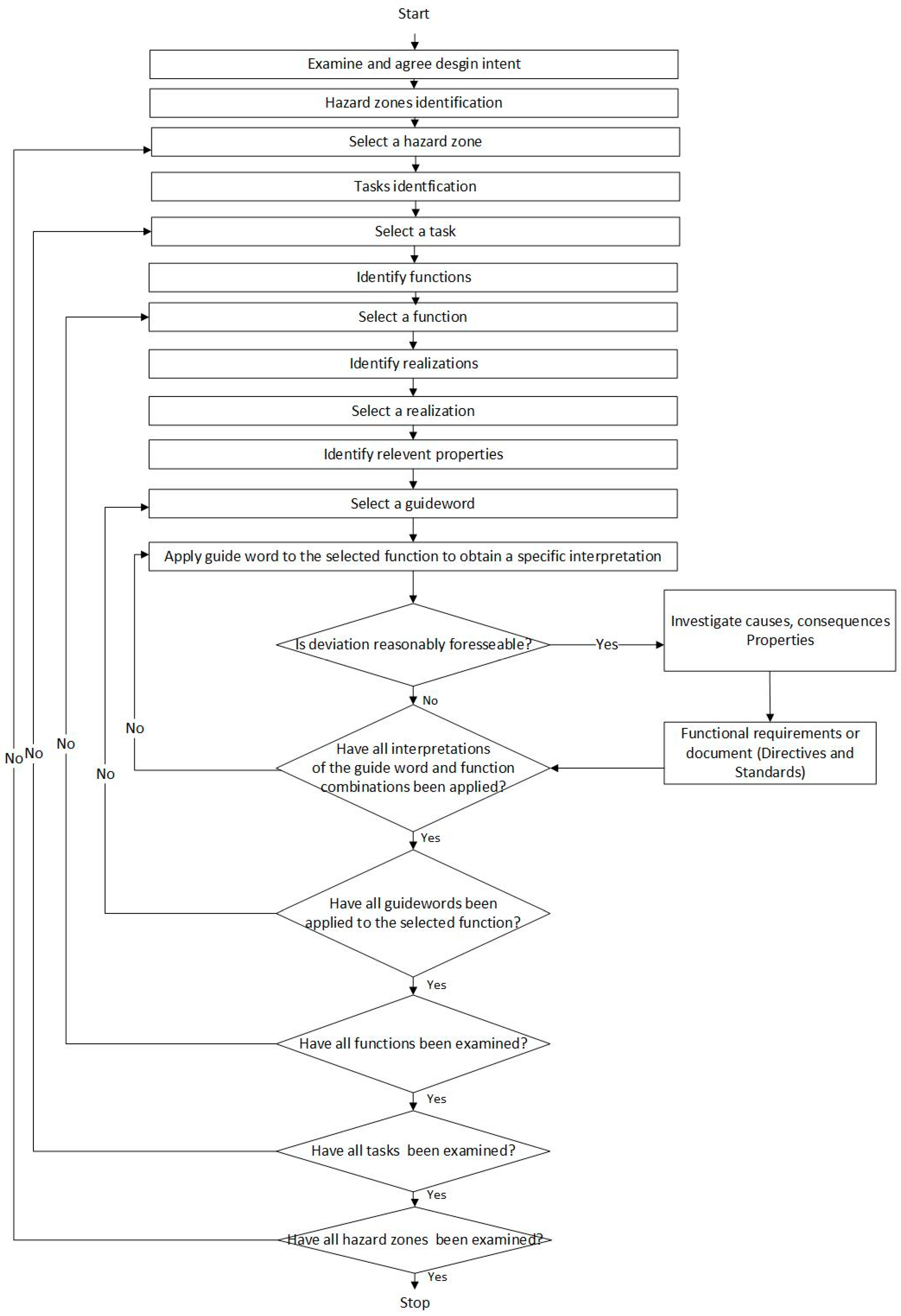
2.4.1. Functional Requirements and Hazard Identification
2.4.2. Functional Safety
- Step 1-Inherently safe design measures: This step focuses on designing robots with built-in safety features and risk-reduction mechanisms from the initial stages. It involves incorporating safety considerations into the design to minimize hazards and risks.
- Step 2-Safeguarding implementation of complementary protective measures: In this step, additional protective measures are implemented alongside the robot to mitigate risks. These measures can include physical barriers, safety sensors, emergency stop buttons, or other safety devices that work in conjunction with the robot.
- Step 3-Information for use: This step involves providing clear and comprehensive instructions, warnings, and guidelines to users about the safe operation and maintenance of the robot. It ensures that users have the necessary information to understand the risks associated with the robot and how to use it safely.
3. Results
3.1. Design Example-Design Intent
3.2. Hazard Zones
- Base zone: The mobile base serves as the module responsible for driving the tractor to its target working position.
- Front zone: The front zone of the machine is designated for the installation of versatile end effectors, such as lifters and other agricultural facilities.
- Electrical system zone: The electrical system zone serves the purpose of electrical power supply and core driving operations, encompassing batteries, circuits, displays, and other electronic components.
- Surrounding zone: The surrounding zone is designated for maintenance personnel and technicians who work in the immediate vicinity of the machine.
3.3. Hazard Identification
3.4. Functional Requirements
3.4.1. Inherent Safer Design
3.4.2. Protective Measures
3.4.3. Information for Use
3.5. Standards Identification
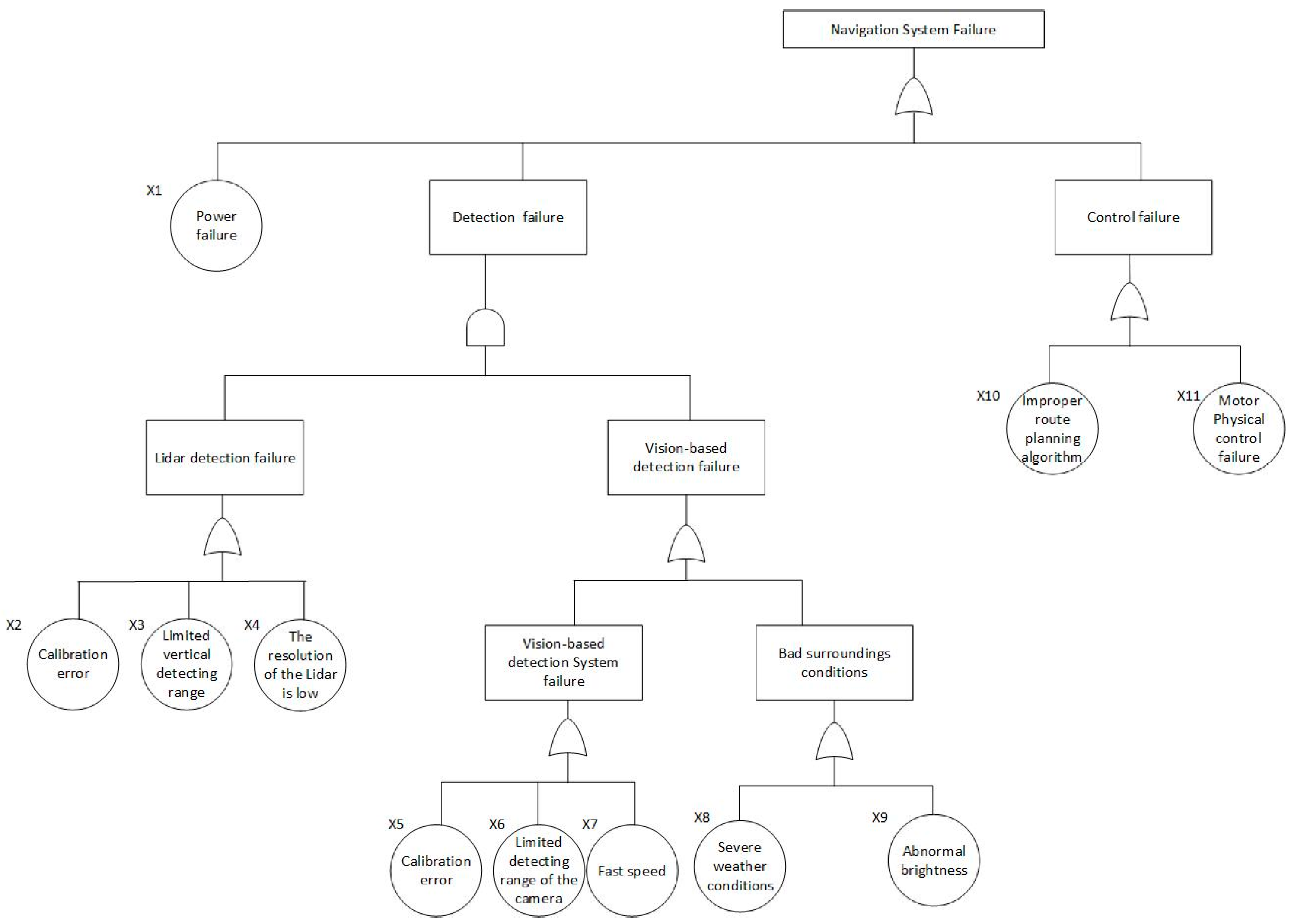
3.6. Functional Safety Based on the FTA Method
4. Discussion
5. Conclusions
Author Contributions
Funding
Institutional Review Board Statement
Informed Consent Statement
Data Availability Statement
Conflicts of Interest
Appendix A

| Function-Centric Hazard Identification | |||||||||
|---|---|---|---|---|---|---|---|---|---|
| HRCA: autonomous agricultural tractor | Hazard zone: Front zone | ||||||||
| The phase of the life cycle: design phase | Analyst: | ||||||||
| Task 1: In the autonomous mode, lift the pruner to the same level of detected leaves and cut. Task 2: Manually disassemble and install attachments. | |||||||||
| Task | Function | Realization | Properties | Guide word | Deviation | Causes | Consequences | Functional requirements | No. |
| 1 | Detect and locate the specific leaves that need to be pruned. | Determine the target object and define the effector target pose according to the perception result. Normally, vision-based algorithms are used to detect the leave type. | 1. Surrounding scene 2. Distance between the tractor and the target | Other than | Instead of the actual target, the tractor recognizes the wrong object, such as wrong leaves, branches, and even stand-by humans. | The implemented target detection algorithms are not precise enough. | Wrong target object positions input to the next function. | 1. Set up use limits on bystanders when the tractor is in autonomous mode. 2. Redundant object detection algorithms are required to compensate for the failure in the primary algorithm. 3. Test and validate the software before implementation. Record the test conditions and review the software documentation. | 2.1.1 |
| Part of | The system can detect partial targets and determine the target pose within a certain error range. | As above | Rough position information input to the next function. | 1. As above, test and validate software before implementation. Record the test conditions and review the software documentation. 2. Enable dynamic setting to switch the detection between high sensitivity (low false negative detection rate) and high robustness (high false negative detection rate but power saving). | 2.1.2 | ||||
| The tractor stops in front of the target and lifts the effector close to the target. | The effector is moved toward the target detected in the previous function. | 1. Tractor pose 2. Effector target pose 3. Effector current pose | Other than | Instead of the actual target, the tractor effector goes toward the wrong object, such as a human. | 1. Wrong input from the previous function. 2. Faults in the effector control system. | 1. Bystanders get injured due to crushing by the effector or other components. 2. Other surrounding objects are damaged by the effector. | 1. Regularly test, validate, and calibrate the effector control system according to standards. 2. Set space limit on bystanders when the effector is working. 3. Set an independent emergency stop function to reduce the risk of standby human injury. Different from 1.1.2, this is an additional emergency stop function that can be installed on a remote control panel to reduce the risk to the surroundings in an emergency. | 2.1.3 | |
| Part of | 1. The effector is able to get close to the target but with some errors. | 1. Inaccurate input from the previous function. 2. Errors from the effector control system. | Damage to the objects around the target leads to cost loss. | Regularly test, validate, and calibrate the effector control system according to standards. | 2.1.4 | ||||
| Execute actions on the target. | The pruner is controlled to cut leaves. The action stops when the target is clear. | 1. Surrounding scene 2. Effector target pose 3. Effector current pose | Part of | Pruned objects accidentally fall from the effectors. | Faults from the effector control system. | Human injury due to falling down parts. | 1. As above 2. Set limits on the maximum lifting weight. | 2.1.5 | |
| 2 | Technician staff disassemble the agricultural | Technicians and maintenance personnel help with changing the agricultural implements for particular tasks. | Usage, installation, and disassembly information about the attachments. | Other than | The wrong implement is installed or disassembled. | Inadequate knowledge of the type of attachments | The mistaken use of the components could lead to hazards such as unbalanced load and structural failure. | 1. Provide a full list of attachments compatible with the equipment in the front zone with the manual. 2. Provide regular training to technicians and maintenance personnel. | 2.2.1 |
| Part of | The disassembly or installation process is improper. | Personnel lack experience. | 1. Human’s fingers, hands, or other body is caught by the pinch points between moving parts such as hydraulic cylinders, linkages, and joints. 2. Severe injury would be caused when the human is caught by the tractor’s power take-off (PTO) system. | 1. Provide detailed, 100% knowable implements installation instructions with the manual. 2. Provide regular training to technicians and maintenance personnel. 3. Provide full protective measures for the maintenance personnel. | 2.2.2 | ||||
| Function-Centric Hazard Identification | |||||||||
|---|---|---|---|---|---|---|---|---|---|
| HRCA: autonomous agricultural tractor | Hazard zone: Electrical system zone | ||||||||
| The phase of the life cycle: design phase | Analyst: | ||||||||
| Task 1: Enable multiple sensors for perception and localization in the autonomous mode. Task 2: Enable USB sockets for attaching electrical devices. | |||||||||
| Task | Function | Realization | Properties | Guide word | Deviation | Causes | Consequences | Functional requirements | No. |
| 1 | Sensors work simultaneously in the autonomous mode. | Sensors are selected based on system requirements and their features. They are connected to the processor, powered by the electrical system. | Sensor specifications | No | Sensors cannot cooperate collaboratively | 1. Poor computational capability of the processor. 2. Interference between sensors. 3. Sensors are not powered properly. | Poor sensor output could lead to failure in the perception system, which will then cause inaccurate or wrong target detection. | 1. Select sensors following instructions of standards. 2. Design mechanical structures to eliminate interference between sensors. 2. Test the electrical power exchange between components. | 3.1.1 |
| 2 | USB sockets support electrical devices communicating with the tractor. | USB sockets are powered by the electrical system. | Electricity power | No | USB sockets cannot enable the connection. | Electrical system faults due to malfunctions such as short circuits, exposed wires, or improper grounding. | Electrical shocks or electrical fires could cause the operator injury or tractor damage. | 1. Test the electrical power exchange between components. 2. Provide proper electrical insulation, grounding, and regular inspection of electrical components. | 3.1.2 |
| Function-Centric Hazard Identification | |||||||||
|---|---|---|---|---|---|---|---|---|---|
| HRCA: autonomous agricultural tractor | Hazard zone: Surrounding zone | ||||||||
| The phase of the life cycle: design phase | Analyst: | ||||||||
| Task 1: The tractor is working together on the field in autonomous mode, with other personnel around. Task 2: The tractor is working together on the field in manual mode, with other personnel around. | |||||||||
| Task | Function | Realization | Properties | Guide word | Deviation | Causes | Consequences | Functional requirements | No. |
| 1 | The tractor is working in autonomous mode while human workers work around it. | The tractor is working in autonomous mode. Assume there is no physical contact between the human and the tractor. | Distance between humans and the tractor. | Part of | Some non-physical hazards could happen to humans when working around the tractor. | 1. low-quality emissions 2. vibrations 3. noise | 1. Facilities/mechanical damage due to the large vibrations during tractor working. 2. Human health such as hearing problems and pulmonary diseases are caused by long-term working in noisy and dirty environments. | 1. A test on the machine’s emission, vibration, and noise level regarding the distance should be conducted under instructions. 2. Provide full protective measures to nearby workers to reduce the risk of emission, vibration, and noise. | 4.1 |
| 2 | The tractor is working on a specific task in manual mode while allowing other personnel to work around it. | The tractor is controlled by the operator. | / | Part of | Emission, vibration, and noise hazards are directly introduced to the operator. | As above | 1. Severe hazards, as mentioned above, would happen to the operator. 2. Discomfort of the operator during working due to mechanical vibration. | 1. As above 2. Tests on emission, vibration, and noise levels should be conducted in the control cab. 3. Provide protective measures to the operator to reduce the risk of emission, vibration, and noise. | 4.2 |
Appendix B
| Related Functional Requirements | Legislation Reference | Reference Number | Standard Title |
|---|---|---|---|
| All | Machinery Regulation 2023/1230/EU | ISO 12100:2011 [12] | Safety of machinery—General principles for design—Risk assessment and risk reduction |
| 1.3.1 | Machinery Regulation 2023/1230/EU | EN 614-1:2006 + A1:2009 [55] EN 614-2 +A1:2008 [56] | Safety of machinery—Ergonomic design principles |
| 1.3.1 | Machinery Regulation 2023/1230/EU | EN 894-1:1997 + A1:2008 [57] EN 894-2:1997+ A1:2008 [58] EN 894-3:2000 + A1:2008 [59] EN 894-4:2010 [60] | Safety of machinery—Ergonomics requirements for the design of displays and control actuators |
| 4.1, 4.2 | Machinery Regulation 2023/1230/EU | EN ISO 14123-1:2015 [61] ISO 14123-2:2015 [62] | Safety of machinery—Reduction of risks to health resulting from hazardous substances emitted by machinery |
| 1.1.1, 1.1.2 | Machinery Regulation 2023/1230/EU | EN ISO 14118: 2018 [36] | Safety of machinery—Prevention of unexpected start-up |
| 1.1.2,1.2.1, 1.2.2, 1.2.3, 1.2.6 | Machinery Regulation 2023/1230/EU | EN ISO 13850:2015 [37] | Safety of machinery—Emergency stop function |
| 2.1.3, 2.1.4, 2.1.5 | Machinery Regulation 2023/1230/EU | EN ISO 4413:2010 [63] | Hydraulic fluid power—General rules and safety requirements for systems and their components |
| 1.2.1 | Machinery Regulation 2023/1230/EU | EN 1837:2020 [38] | Safety of machinery—Integral lighting of machines |
| 1.2.6, 1.3.2, 2.1.3, 2.1.4 | Machinery Regulation 2023/1230/EU | EN ISO 13849-1:2023 [39] EN ISO 13849-2:2014 [40] | Safety of machinery—Safety-related parts of control system |
| 4.1, 4.2 | Machinery Regulation 2023/1230/EU | EN 13490 + A1:2008 [64] | Mechanical vibration—Industrial trucks—Laboratory evaluation and specification of operator seat vibration |
| 1.2.6, 1.3.2, 2.1.3, 2.1.4 | Machinery Regulation 2023/1230/EU | EN ISO 25119-1: 2023 [41] EN ISO 25119-1: 2023/A1: 2023 [42] EN ISO 25119-2: 2023 [43] EN ISO 25119-3: 2023 [44] EN ISO 25119-3: 2023/A1: 2023 [45] EN ISO 25119-4: 2023 [46] EN ISO 25119-4: 2023/A1: 2023 [47] | Tractors and machinery for agriculture and forestry—Safety-related parts of control systems |
| 1.1.1, 1.1.2, 1.2.1, 1.2.2, 1.2.3, 1.2.4, 1.2.5, 1.2.6, 2.1.1, 2.1.2, 2.1.3, 2.1.4 | Machinery Regulation 2023/1230/EU | EN ISO 18497:2018 [48] | Agricultural machinery and tractors–Safety of highly automated agricultural machines—Principles for design |
| 2.1.5, 2.2.1, 2.2.2 | Machinery Regulation 2023/1230/EU | EN ISO 16231-1:2013 [65] EN ISO 16231-2:2015 [66] | Self-propelled agricultural machinery—Assessment of stability |
| 2.2.1, 2.2.2 | Machinery Regulation 2023/1230/EU | EN ISO 16230-1:2015 [67] | Agricultural machinery and tractors—Safety of higher voltage electrical and electronic components and systems—Part 1: General requirements |
| 2.2.2 | Machinery Regulation 2023/1230/EU | EN 12965:2019 [68] | Tractors and machinery for agriculture and forestry—Power take-off (PTO) drive shafts and their guards—Safety |
| 1.2.3, 1.2.4 | The Low Voltage Directive (LVD) 2014/35/EU | EN ISO 11252:2013 [49] | Lasers and laser-related equipment—Laser device—Minimum requirements for documentation |
| 1.2.3, 1.2.4 | The Low Voltage Directive (LVD) 2014/35/EU | DS/EN 60825:2014 [50] | Safety of laser products |
| 3.1.1, 3.1.2 | The Low Voltage Directive (LVD) 2014/35/EU | EN 61010-1:2010 [69] | Safety requirements for electrical equipment for measurement, control, and laboratory use |
| 1.1.1, 1.1.2 | The Low Voltage Directive (LVD) 2014/35/EU | EN IEC 60947-1:2021 [51] | Low-voltage switchgear and control gear |
| 1.1.1, 1.1.2, 1.2.1, 1.2.2, 1.2.3, 1.2.4, 1.2.5, 1.2.6, 2.1.1, 2.1.2, 2.1.3, 2.1.4, 3.1.1 | The Low Voltage Directive (LVD) 2014/35/EU | EN IEC 62368-1:2024 [52] IEC TR 62368-2: 2019 [53] EN IEC 62368:3-2020 [54] | Audio/video, information and communication technology equipment |
| 3.1.1 | The Electromagnetic Compatibility (EMC) Directive 2014/30/EU | EN ISO 14982:2009 [70] | Agricultural and forestry machinery—Electromagnetic compatibility—Test methods and acceptance criteria |
| 3.1.2 | The Low Voltage Directive (LVD) 2014/35/EU | EN IEC 61204-7:2018 [71] | Low-voltage switch mode power supplies—Part 7: Safety requirements |
| 2.1.3 | The Radio Equipment Directive 2014/53/EU | ETSI EN 303 413 V1.2.1:2021 [72] | Satellite Earth Stations and Systems (SES); Global Navigation Satellite System (GNSS) receivers; Radio equipment operating in the 1164 MHz to 1300 MHz and 1559 MHz to 1610 MHz frequency bands |
References
- Franklin, C.S.; Dominguez, E.G.; Fryman, J.D.; Lewandowski, M.L. Collaborative Robotics: New Era of Human–Robot Cooperation in the Workplace. J. Safety Res. 2020, 74, 153–160. [Google Scholar] [CrossRef] [PubMed]
- Adriaensen, A.; Costantino, F.; Di Gravio, G.; Patriarca, R. Teaming with Industrial Cobots: A Socio-Technical Perspective on Safety Analysis. Hum. Factors Ergon. Manuf. 2022, 32, 173–198. [Google Scholar] [CrossRef]
- Lincoln, J.M.; Elliott, K.C. Emerging Technology in Agriculture: Opportunities and Considerations for Occupational Safety and Health Researchers. J. Saf. Res. 2023, 86, 92–95. [Google Scholar] [CrossRef]
- Mcalinden, J.J. Using robotics as an occupational-health and safety control strategy. Ind. Robot 1995, 22, 14–17. [Google Scholar] [CrossRef]
- Aven, T. Foundational Issues in Risk Assessment and Risk Management. Risk Anal. 2012, 32, 1647–1656. [Google Scholar] [CrossRef] [PubMed]
- Dhillon, B.S.; Fashandi, A.R.M.; Liu, K.L. Robot Systems Reliability and Safety: A Review. J. Qual. Maint. Eng. 2002, 8, 170–212. [Google Scholar] [CrossRef]
- Huck, T.P.; Münch, N.; Hornung, L.; Ledermann, C.; Wurll, C. Risk Assessment Tools for Industrial Human-Robot Collaboration: Novel Approaches and Practical Needs. Saf. Sci. 2021, 141, 105288. [Google Scholar] [CrossRef]
- Giallanza, A.; La Scalia, G.; Micale, R.; La Fata, C.M. Occupational Health and Safety Issues in Human-Robot Collaboration: State of the Art and Open Challenges. Saf. Sci. 2024, 169, 106313. [Google Scholar] [CrossRef]
- Berx, N.; Decré, W.; Morag, I.; Chemweno, P.; Pintelon, L. Identification and Classification of Risk Factors for Human-Robot Collaboration from a System-Wide Perspective. Comput. Ind. Eng. 2022, 163, 107827. [Google Scholar] [CrossRef]
- Franklin, C. The Role of Standards in Human–Robot Integration Safety. In Intelligent Systems, Control and Automation: Science and Engineering; Springer Science and Business Media B.V.: Berlin/Heidelberg, Germany, 2022; Volume 81, pp. 155–171. ISBN 22138994, 22138986. [Google Scholar]
- Berx, N.; Adriaensen, A.; Decré, W.; Pintelon, L. Assessing System-Wide Safety Readiness for Successful Human–Robot Collaboration Adoption. Safety 2022, 8, 48. [Google Scholar] [CrossRef]
- ISO 12100:2010; Safety of Machinery—General Principles for Design—Risk Assessment and Risk Reduction. ISO: Geneva, Switzerland, 2011.
- ISO/TS 15066:2016; Robots and Robotic Devices—Collaborative Robots. ISO: Geneva, Switzerland, 2016.
- ISO 10218-1:2011; Robots and Robotic Devices—Safety Requirements for Industrial Robots—Part 1: Robots. ISO: Geneva, Switzerland, 2011.
- ISO 10218-2:2011; Robots and Robotic Devices—Safety Requirements for Industrial Robots—Part 2: Robot Systems and Integration. ISO: Geneva, Switzerland, 2011.
- Chemweno, P.; Pintelon, L.; Decre, W. Orienting Safety Assurance with Outcomes of Hazard Analysis and Risk Assessment: A Review of the ISO 15066 Standard for Collaborative Robot Systems. Saf. Sci. 2020, 129, 104832. [Google Scholar] [CrossRef]
- Chang, Y.; Khan, F.; Ahmed, S. A Risk-Based Approach to Design Warning System for Processing Facilities. Process Saf. Environ. Prot. 2011, 89, 310–316. [Google Scholar] [CrossRef]
- Saenz, J.; Bessler-Etten, J.; Valori, M.; Prange-Lasonder, G.B.; Fassi, I.; Bidard, C.; Lassen, A.B.; Paniti, I.; Toth, A.; Stuke, T.; et al. An Online Toolkit for Applications Featuring Collaborative Robots Across Different Domains. IEEE Trans. Hum.-Mach. Syst. 2022, 53, 657–667. [Google Scholar] [CrossRef]
- Krishnan, R.; Bhada, S.V. An Integrated System Design and Safety Framework for Model-Based Safety Analysis. IEEE Access 2020, 8, 146483–146497. [Google Scholar] [CrossRef]
- Lind, M. Foundations for Functional Modeling of Technical Artefacts; Springer: Berlin/Heidelberg, Germany, 2023; ISBN 3031459172, 3031459180, 9783031459177, 9783031459184. [Google Scholar]
- Broy, M.H.B. From System Requirements Documents to Integrated System Modeling Artifacts. In Proceedings of the 9th ACM Symposium on Document Engineering, Munich, Germany, 15–18 September 2009. [Google Scholar]
- Brown, D.C.; Chandrasekaran, B. Design Problem Solving; Morgan Kaufmann: Burlington, MA, USA, 1989; ISBN 0273087665, 1322471142, 1483258882, 9780273087663, 9781322471143, 9781483258881. [Google Scholar]
- U.S. Congress. Government Performance and Results Act of 1993. In 103rd Congress; Congressional Record: Washington, DC, USA, 1993. [Google Scholar]
- Saji, G. Safety Goals in “risk-Informed, Performance-Based” Regulation. Reliab. Eng. Syst. Saf. 2003, 80, 163–172. [Google Scholar] [CrossRef]
- Laurie, G.; Harmon, S.H.E.; Arzuaga, F. Foresighting Futures: Law, New Technologies, and the Challenges of Regulating for Uncertainty. Law Innov. Technol. 2012, 4, 1–33. [Google Scholar] [CrossRef]
- Center for Chemical Process Safety (CCPS). Guidelines for Risk Based Process Safety; CCPS: Hoboken, NJ, USA, 2007. [Google Scholar]
- Van Eerd, D. Knowledge Transfer and Exchange in Health and Safety: A Rapid Review. Policy Pract. Health Saf. 2019, 17, 54–77. [Google Scholar] [CrossRef]
- Chakrabarti, A.; Bligh, T.P. A Scheme for Functional Reasoning in Conceptual Design. Des. Stud. 2001, 22, 493–517. [Google Scholar] [CrossRef]
- Li, R.; Wu, J.; Ravn, O.; Zhang, X. Analyzing Hazards in Process Systems Using Multilevel Flow Modelling: Challenges and Opportunities. In Proceedings of the 32nd European Safety and Reliability Conference, Dublin, Ireland, 28 August–1 September 2022; pp. 1441–1448. [Google Scholar]
- Guiochet, J. Hazard Analysis of Human-Robot Interactions with HAZOP-UML. Saf. Sci. 2016, 84, 225–237. [Google Scholar] [CrossRef]
- Wu, J.; Lind, M. Management of System Complexity in HAZOP for the Oil &Gas Industry. Ifac-Pap. 2018, 51, 211–216. [Google Scholar] [CrossRef]
- Inam, R.; Raizer, K.; Hata, A.; Souza, R.; Forsman, E.; Cao, E.; Wang, S. Risk Assessment for Human-Robot Collaboration in an Automated Warehouse Scenario. In Proceedings of the 2018 IEEE 23rd International Conference on Emerging Technologies and Factory Automation (ETFA), Torino, Italy, 4–7 September 2018; Volume 1, pp. 743–751. [Google Scholar]
- Aby, G.R.; Issa, S.F. Safety of Automated Agricultural Machineries: A Systematic Literature Review. Safety 2023, 9, 13. [Google Scholar] [CrossRef]
- Modarres, M. Functional Modeling of Complex Systems with Applications. In Proceedings of the IEEE Annual Reliability and Maintainability Symposium, Washington, DC, USA, 18–21 January 1999; pp. 418–425. [Google Scholar]
- IEC 61882:2016; Hazard and Operability Studies (HAZOP Studies)—Application Guide. International Electrotechnical Commission: Geneva, Switzerland, 2016.
- EN ISO 14118:2018; Safety of Machinery—Prevention of Unexpected Start-Up. CEN: Brussels, Belgium, 2018.
- EN ISO 13850:2015; Safety of Machinery—Emergency Stop Function—Principles for Design. CEN: Brussels, Belgium, 2015.
- EN 1837:2020; Safety of Machinery—Integral Lighting of Machines. CEN: Geneva, Switzerland, 2020.
- EN ISO 13849-1:2023; Safety of Machinery—Safety-Related Parts of Control Systems—Part 1: General Principles for Design. CEN: Brussels, Belgium, 2023.
- EN ISO 13849-2:2012; Safety of Machinery—Safety-Related Parts of Control Systems—Part 2: Validation. CEN: Brussels, Belgium, 2023.
- EN ISO 25119-1:2023; Tractors and Machinery for Agriculture and Forestry—Safety-Related Parts of Control Systems—Part 1: General Principles for Design and Development. CEN: Brussels, Belgium, 2023.
- EN ISO 25119-1:2023/A1:2023; Tractors and Machinery for Agriculture and Forestry—Safety-Related Parts of Control Systems—Part 1: General Principles for Design and Development—Amendment 1. CEN: Brussels, Belgium, 2023.
- EN ISO 25119-2:2023; Tractors and Machinery for Agriculture and Forestry—Safety-Related Parts of Control Systems—Part 2: Concept Phase. CEN: Brussels, Belgium, 2023.
- EN ISO 25119-3:2023; Tractors and Machinery for Agriculture and Forestry—Safety-related parts of Control Systems—Part 3: Series Development, Hardware and Software. CEN: Brussels, Belgium, 2023.
- EN ISO 25119-3:2023/A1:2023; Tractors and Machinery for Agriculture and Forestry—Safety-Related Parts of Control Systems—Part 3: Series Development, Hardware and Software—Amendment 1. CEN: Brussels, Belgium, 2023.
- EN ISO 25119-4:2023; Tractors and Machinery for Agriculture and Forestry—Safety-Related Parts of Control Systems—Part 4: Production, Operation, Modification and Supporting Processes. CEN: Brussels, Belgium, 2023.
- EN ISO 25119-4:2023/A1:2023; Tractors and Machinery for Agriculture and Forestry—Safety-Related Parts of Control Systems—Part 4: Production, Operation, Modification and Supporting Processes—Amendment 1. CEN: Brussels, Belgium, 2023.
- EN ISO 18497:2018; Agricultural Machinery and Tractors—Safety of Highly Automated Agricultural Machines—Principles for Design. CEN: Brussels, Belgium, 2018.
- EN ISO 11252:2013; Lasers and Laser-Related Equipment—Laser Device—Minimum Requirements for Documentation. CEN: Brussels, Belgium, 2013.
- EN ISO 60825:2014; Safety of Laser Products—Part 1: Equipment Classification and Requirements. CEN: Brussels, Belgium, 2014.
- EN IEC 60947-1:2021; Low-Voltage Switchgear and Controlgear—Part 1: General Rules. CEN: Brussels, Belgium, 2021.
- EN IEC 62368-1:2024; Audio/Video, Information and Communication Technology Equipment—Part 1: Safety Requirements. CEN: Brussels, Belgium, 2024.
- IEC TR 62368-2:2019; Audio/Video, Information and Communication Technology Equipment—Part 2: Explanatory Information Related to IEC 62368-1:2018. IEC: Geneva, Switzerland, 2019.
- EN IEC 62368-3:2020; Audio/Video, Information and Communication Technology Equipment—Part 3: Safety Aspects for DC Power Transfer Through Communication Cables and Ports. CEN: Brussels, Belgium, 2020.
- EN 614-1:2006+A1:2009; Safety of Machinery—Ergonomic Design Principles—Part 1: Terminology and General Principles. CEN: Brussels, Belgium, 2009.
- EN 614-2:2000+A1:2008; Safety of Machinery—Ergonomic Design Principles—Part 2: Interactions Between the Design of Machinery and Work Tasks. CEN: Brussels, Belgium, 2008.
- EN 894-1:1997+A1:2008; Safety of Machinery—Ergonomics Requirements for the Design of Displays and Control Actuators—Part 1: General Principles for Human Interactions with Displays and Control Actuators. CEN: Brussels, Belgium, 2008.
- EN 894-2:1997+A1:2008; Safety of Machinery—Ergonomics Requirements for the Design of Displays and Control Actuators—Part 2: Displays. CEN: Brussels, Belgium, 2008.
- EN 894-3:2000+A1:2008; Safety of Machinery—Ergonomics Requirements for the Design of Displays and Control Actuators—Part 3: Control Actuators. CEN: Brussels, Belgium, 2008.
- EN 894-4:2010; Safety of Machinery—Ergonomics Requirements for the Design of Displays and Control Actuators—Part 4: Location and Arrangement of Displays and Control Acturators. CEN: Brussels, Belgium, 2010.
- EN ISO 14123-1:2015; Safety of Machinery—Reduction of Risks to Health Resutling from Hazardous Substances Emitted by Machinery—Part 1: Principles and Specifications for Machinery Manufacturers. CEN: Brussels, Belgium, 2015.
- EN ISO 14123-2:2015; Safety of Machinery—Reduction of Risks to Health Resutling from Hazardous Substances Emitted by Machinery—Part 2: Methodology Leading to Verfication Procedures. CEN: Brussels, Belgium, 2015.
- EN ISO 4413:2010; Hydraulic Fluid Power—General Rules and Safety Requirements for Systems and Their Components. CEN: Brussels, Belgium, 2010.
- EN 13490:2001+A1:2008; Mechanical Vibration—Industrial Trucks—Laboratory Evaluation and Specification of Operator Seat Vibration. CEN: Brussels, Belgium, 2008.
- EN ISO 16231-1:2013; Self-Propelled Agricultural Machinery—Assessment of Stability—Part 1: Principles. CEN: Brussels, Belgium, 2013.
- EN ISO 16231-2:2015; Self-propelled Agricultural Machinery—Assessment of Stability—Part 2: Determination of Static Stability and Test Procedures. CEN: Brussels, Belgium, 2015.
- EN ISO 16230-1:2015; Agricultural Machinery and Tractors—Safety of Higher Voltage Electrical and Electronic Components and Systems—Part 1: General Requirements. CEN: Brussels, Belgium, 2015.
- EN 12965:2019; Tractors and Machinery for Agriculture and Forestry—Power Take-Off (PTO) Drive Shafts and Their Guards—Safety. CEN: Brussels, Belgium, 2019.
- EN 61010-1:2020; Safety Requirements for Electrical Equipment for Measurement, Control, and Laboratory Use—Part 1: General Requirements. CEN: Brussels, Belgium, 2010.
- EN ISO 14982:2009; Agricultural and Forestry Machinery—Electromagnetic Compatibility—Test Methods and Acceptance Criteria. CEN: Brussels, Belgium, 2009.
- EN IEC 61204-7:2018; Low-Voltage Switch Mode Power Supplies—Part 7: Safety Requirements. CEN: Brussels, Belgium, 2009.
- ETSI EN 303 413 V1.2.1:2021; Satellite Earth Stations and Systems (SES); Global Navigation Satellite System (GNSS) Receivers; Radio equipment Operating in the 1164 MHz to 1300 MHz and 1559 MHz to 1610 MHz Frequency Bands; Harmonised Standard for Access to Radio Spectrum. ETSI: Sophia-Antipolis, France, 2009.


| Function-Centric Hazard Identification | ||||||||
|---|---|---|---|---|---|---|---|---|
| HRC: | Hazard zone: | |||||||
| The phase of the life cycle: | Analyst: | |||||||
| Task | Function | Realization | Properties | Guide word | Deviation | Causes | Consequences | Functional requirement |
| Function-Centric Hazard Identification | |||||||||
|---|---|---|---|---|---|---|---|---|---|
| HRCA: autonomous agricultural tractor | Hazard zone: Base zone | ||||||||
| The phase of the life cycle: design phase | Analyst: | ||||||||
| Task | Function | Realization | Properties | Guide word | Deviation | Causes | Consequences | Functional requirements | No. |
| 1 | Switch between the autonomous mode and the manual mode | Manually select the option | Machine status | Other than | Autonomous mode fails to start | Software error | The tractor cannot move. Time loss. | 1. Set up at least two distinct accesses (for redundancy and safety, e.g., a mechanical button reachable when the operator is outside the tractor and an access on the control panel) to the mode switch while also minimizing the effect of complexity from multiple systemic accesses. 2. Provide 100% knowable instructions on how to switch the mode (for good decision support in the situation of autonomous mode failing to start to reduce possible human errors) in the user manual, considering the diverse educational level of the intended users. Two necessary formats of instructions can be diagram instructions showing appearances and positions of accesses and language instructions to describe operations in detail. Note that multiple languages and definitions of terminologies are expected to be provided to meet the needs of people from different educational backgrounds. | 1.1.1 |
| Other than | The autonomous mode starts before the operator leaves the tractor. | As above | Extra injury to the operator when the collision happens. | 1. As above. 2. Set up an independent emergency stop function that shall stop all hazardous motions and should be clearly marked and easily accessible. It shall only be reset by a deliberate manual action that does not cause a restart after resetting but shall only permit a restart to occur. The following information shall be provided: (a) stop category according to IEC 60204-1:2016 + AMD1: 2021. (b) span-of-control of the emergency stop; (c) maximum response time for the emergency stop, as measured from input state change until the termination of the hazardous function of the tractor. (d) maximum stopping time for the emergency stop, as measured from input state change until the termination of hazard function(s) of the tractor. | 1.1.2 | ||||
| 2 | Perceive surroundings among dynamic objects, static obstacles, and drivable paths. | Camera detection with image processing algorithms and learning approach | 1. Object type 2. Distance | No | The tractor fails to detect its surroundings, especially the road. | 1. Blurry image due to the instability of the tractor 2. Weak brightness 3. Severe weather conditions | 1. There is no valid input to the localization and navigation module. 2. The tractor fails to start the autonomous mode or moves improperly. | 1. Set up specific limitations on maximum driving and turning speeds given different types of risky weather in autonomous mode in the user manual, providing 100% fully clear instructions to manually select operation conditions or set speed limitations (for good decision support to reduce human errors) considering a diverse educational level of the intended users. 2. Set up two image quality assessment modules: a subjective test module where humans can access captured images and provide evaluations and an objective test module where the computational software enables the comparison between references and targets. Use images with rain droplets, snow particles, and dust to simulate extreme conditions. Compare the module’s output with known benchmarks for images in similar conditions. The verification and validation methods are a review of the documentation and information for use, practical tests, and simulation tests. Record the test conditions. Quality assessment is expected to start once the autonomous mode starts. The captured images are tested on several factors: brightness, resolution, contrast, noise, and blur. The system should have instant feedback on whether the series of input images is valid for autonomous navigation. If not, disable the autonomous mode. 3. Set up an emergency stop function as explained in 1.1.2. 4. Test the lighting system. The verification and validation methods are visual inspection, observation during operation, review of specifications and information for use, and practical tests. | 1.2.1 |
| Part of | 1. Not all obstacles in the scene are detected. 2. Distance between the tractor and the object is not available. | 1. low-quality image 2. unreliable detection algorithm 3. limited detecting range of the camera | The tractor is not aware of changes in surroundings, which may cause collisions. | 1. Set limitations on sensing and automation-related zones in the user manual, providing 100% fully clear instructions (for good decision support to reduce human errors) considering the diverse educational level of the intended users. Provide speed monitoring safety functions. 2. Analyze sensor performance classes and test detection capabilities of the sensors and software before implementation in the real-case application. Set specific, measurable criteria to assess the performance of sensors and software. Record the test conditions. 3. Set up an emergency stop function, see 1.1.2. | 1.2.2 | ||||
| Lidar detection | 1. Distance 2. Reflective data | Part of | Not all obstacles are detected by Lidar. | 1. The resolution of the Lidar is too low. 2. The vertical detecting range is limited. | As above | As above | 1.2.3 | ||
| Task | Function | Realization | Properties | Guide word | Deviation | Causes | Consequences | Functional requirements | No. |
| combination of sensors | 1. Object type 2. Distance 3. Reflective data | Part of | The detection is not as accurate as expected. | Calibration and data alignment between sensors are not conducted properly. | As above | 1. As above 2. Provide 100% knowable instructions on how to perform the calibration of onboard sensors, e.g., camera, depth camera, and LiDAR in this case study (for good decision support to reduce possible human errors) in the user manual, considering the diverse educational levels of the intended users. | 1.2.4 | ||
| Planning collision-free trajectory based on perception result. | The route is generated according to certain rules or traditional collision avoidance algorithms such as potential field methods | 1. Knowledge of the environment (perception results) 2. Trajectory generation algorithm(s) | No/Part of | No trajectory is generated, or the provided trajectory cannot meet the collision-free requirement. | An improper route planning algorithm is used. | 1. The tractor cannot avoid obstacles duly. 2. The tractor cannot drive on the expected path, i.e., The middle of the field trial. | 1. Test the trajectory planning algorithm before implementation on the machine. Set specific, measurable criteria to assess the performance of the trajectory planning algorithm in both simulation and real implementation. Record the test conditions. 2. Calibrate the path at first use. Provide 100% knowable instructions on how to perform the calibration (for good decision support to reduce possible human errors) in the user manual, considering the diverse educational levels of the intended users. | 1.2.5 | |
| Control the tractor driving on the expected trajectory. | The motor is controlled through specific control theories | 1. Trajectory 2. The difference between the expected route and the driving on route 3. Constraints 4. Machine states | Part of | The control result is not as expected. | 1. The parameter from the control system is not set properly. 2. The electrical module and the mechanical module are not well-compatible. | 1. Component damage because the tractor cannot drive smoothly. 2. The tractor cannot follow the expected path. 3. Collision due to the tractor cannot react to the environment on time. | 1. Provide suggested control parameters according to the ground condition. Test the control system before implementation. Record the test conditions. 2. Set up an emergency stop function, see 1.1.2. | 1.2.6 | |
| 3 | The operator gives direct command to the tractor. | The operator sits in the driver’s seat and controls the tractor through the control panel | Machine states | Part of | The human operator can control the tractor but fails to do it safely. | 1. Operator’s clothing, hair, or body parts get caught or entangled in mechanical parts and cause injury or entrapment. 2. Operator’s inadequate awareness and understanding of the control system. 3. Human is injured due to bad ergonomics. | 1. Collision, turnover, and other accidents due to human failure. 2. Human injury due to long-term work. | 1. Set limits on operators. 2. Design the seat and the panel to follow the relevant standards to fully fulfill the requirements of human factor engineering. 3. Provide 100% knowable instructions on control systems (for good decision support to reduce possible human errors) in the user manual, considering the diverse educational levels of the intended users. 4. Provide protective measures in the cab. | 1.3.1 |
| The control system conducts command from the operator. | The coordination between the electrical system with the engine and actuator | Machine states | Part of | The control system cannot react to the command on time. | Malfunctions in the electrical control system and the mechanical control system. | Collision, turnover, and other accidents due to malfunctions. | Test the control system in the manual mode before implementation. Record the test. | 1.3.2 | |
| Related Functional Requirements | Legislation Reference | Reference Number | Standard Title |
|---|---|---|---|
| All | Machinery Regulation 2023/1230/EU | ISO 12100:2011 [12] | Safety of machinery—General principles for design—Risk assessment and risk reduction |
| 1.1.1, 1.1.2 | Machinery Regulation 2023/1230/EU | EN ISO 14118: 2018 [36] | Safety of machinery—Prevention of unexpected start-up |
| 1.1.2 | Machinery Regulation 2023/1230/EU | EN ISO 13850:2015 [37] | Safety of machinery—Emergency stop function |
| 1.2.1 | Machinery Regulation 2023/1230/EU | EN 1837:2020 [38] | Safety of machinery—Integral lighting of machines |
| 1.2.6, 1.3.2 | Machinery Regulation 2023/1230/EU | EN ISO 13849-1:2023 [39] EN ISO 13849-2:2012 [40] | Safety of machinery—Safety-related parts of control system |
| 1.2.6, 1.3.2 | Machinery Regulation 2023/1230/EU | EN ISO 25119-1: 2023 [41] EN ISO 25119-1: 2023/A1: 2023 [42] EN ISO 25119-2: 2023 [43] EN ISO 25119-3: 2023 [44] EN ISO 25119-3: 2023/A1: 2023 [45] EN ISO 25119-4: 2023 [46] EN ISO 25119-4: 2023/A1: 2023 [47] | Tractors and machinery for agriculture and forestry—Safety-related parts of control systems |
| 1.1.1, 1.1.2, 1.2.1, 1.2.2, 1.2.3, 1.2.4, 1.2.5, 1.2.6 | Machinery Regulation 2023/1230/EU | EN ISO 18497:2018 [48] | Agricultural machinery and tractors–Safety of highly automated agricultural machines—Principles for design |
| 1.2.3, 1.2.4 | The low voltage directive (LVD) 2014/35/EU | EN ISO 11252:2013 [49] | Lasers and laser-related equipment—Laser device—Minimum requirements for documentation |
| 1.2.3, 1.2.4 | The low voltage directive (LVD) 2014/35/EU | DS/EN 60825-1:2014 [50] | Safety of laser products |
| 1.1.1, 1.1.2 | The low voltage directive (LVD) 2014/35/EU | EN IEC 60947-1: 2021 [51] | Low-voltage switchgear and control gear |
| 1.1.1, 1.1.2, 1.2.1, 1.2.2, 1.2.3, 1.2.4, 1.2.5, 1.2.6 | The low voltage directive (LVD) 2014/35/EU | EN IEC 62368-1:2024 [52] IEC TR 62368-2: 2019 [53] EN IEC 62368:3-2020 [54] | Audio/video, information and communication technology equipment |
| Scenario | Classification of Injuries (S) | Classification of Exposure to the Hazardous Situation (E) | Classification of Avoidance of Harm (C) | PLr |
|---|---|---|---|---|
| X1 | S0 | N.A. | C2 | QM |
| X10 | S2 | E2 | C3 | b |
| X11 | S0 | N.A. | C2 | QM |
| X2, X5 | S2 | E2 | C3 | b |
| X2, X6 | S2 | E2 | C3 | b |
| X2, X7 | S3 | E2 | C3 | c |
| X2, X8 | S2 | E2 | C3 | b |
| X2, X9 | S2 | E2 | C3 | b |
| X3, X5 | S2 | E2 | C3 | b |
| X3, X6 | S2 | E2 | C3 | b |
| X3, X7 | S3 | E2 | C3 | c |
| X3, X8 | S2 | E2 | C3 | b |
| X3, X9 | S2 | E2 | C3 | b |
| X4, X5 | S2 | E2 | C3 | b |
| X4, X6 | S2 | E2 | C3 | b |
| X4, X7 | S3 | E2 | C3 | c |
| X4, X8 | S2 | E2 | C3 | b |
| X4, X9 | S2 | E2 | C3 | b |
Disclaimer/Publisher’s Note: The statements, opinions and data contained in all publications are solely those of the individual author(s) and contributor(s) and not of MDPI and/or the editor(s). MDPI and/or the editor(s) disclaim responsibility for any injury to people or property resulting from any ideas, methods, instructions or products referred to in the content. |
© 2025 by the authors. Licensee MDPI, Basel, Switzerland. This article is an open access article distributed under the terms and conditions of the Creative Commons Attribution (CC BY) license (https://creativecommons.org/licenses/by/4.0/).
Share and Cite
Wu, J.; Ren, J.; Ravn, O.; Nalpantidis, L. A Risk-Informed Design Framework for Functional Safety System Design of Human–Robot Collaboration Applications. Safety 2025, 11, 24. https://doi.org/10.3390/safety11010024
Wu J, Ren J, Ravn O, Nalpantidis L. A Risk-Informed Design Framework for Functional Safety System Design of Human–Robot Collaboration Applications. Safety. 2025; 11(1):24. https://doi.org/10.3390/safety11010024
Chicago/Turabian StyleWu, Jing, Junru Ren, Ole Ravn, and Lazaros Nalpantidis. 2025. "A Risk-Informed Design Framework for Functional Safety System Design of Human–Robot Collaboration Applications" Safety 11, no. 1: 24. https://doi.org/10.3390/safety11010024
APA StyleWu, J., Ren, J., Ravn, O., & Nalpantidis, L. (2025). A Risk-Informed Design Framework for Functional Safety System Design of Human–Robot Collaboration Applications. Safety, 11(1), 24. https://doi.org/10.3390/safety11010024