Abstract
Towards a sustainable future in construction, worldwide efforts aim to reduce cement use as a binder core material in concrete, addressing production costs, environmental concerns, and circular economy criteria. In the last decade, numerous studies have explored cement substitutes (e.g., fly ash, silica fume, clay-based materials, etc.) and methods to mimic the mechanical performance of cement by integrating polymeric meshes into their matrix. In this study, a systemic approach incorporating computer aid and biomimetics is utilized for the development of 3D-printed clay-based composite mortar reinforced with advanced polymeric bioinspired lattice structures, such as honeycombs and Voronoi patterns. These natural lattices were designed and integrated into the 3D-printed clay-based prisms. Then, these configurations were numerically examined as bioinspired lattice applications under three-point bending and realistic loading conditions, and proper Finite Element Models (FEMs) were developed. The extracted mechanical responses were observed, and a conceptual redesign of the bioinspired lattice structures was conducted to mitigate high-stress concentration regions and optimize the structures’ overall mechanical performance. The optimized bioinspired lattice structures were also examined under the same conditions to verify their mechanical superiority. The results showed that the clay-based prism with honeycomb reinforcement revealed superior mechanical performance compared to the other and is a suitable candidate for further research. The outcomes of this study intend to further research into non-cementitious materials suitable for industrial and civil applications.
1. Introduction
Additive manufacturing (AM) is becoming increasingly popular and proving its benefits across various sectors [,,,]. Due to its ability to create complex geometric shapes, AM is becoming a game-changing technology in the construction industry [,,,]. The advantages it offers are numerous, including reducing labor accidents, construction time, and total costs, and providing construction freedom, making its adoption inevitable [,,]. Additionally, AM enables eco-friendly construction methodologies, which are crucial [,]. To date, new 3D printing systems with multiple innovations have emerged, offering reliable and innovative construction solutions for both small structures like kiosks, bridges, and benches, and larger-scale projects such as residences and shops [,,,,]. These innovations are also vital for quick building repairs and creating temporary housing in disaster situations like earthquakes [,,,].
The AM technology used for building purposes can be found in the literature referred to as 3D mortar printing (3DMP), 3D concrete printing (3DCP), and liquid deposition modeling (LDM) [,,,]. All these methodologies share the use of a liquid or paste-like mixture suitable for building purposes. By applying this mixture with layer-by-layer extrusion, the desired geometry is achieved [,]. A less developed method in 3D concrete printing is shotcrete 3D printing, which utilizes a shotcrete spraying nozzle mounted on an articulated robotic arm to apply concrete and construct a structure based on a digital design. This method addresses weak interlayer bonding by spraying concrete at high pressure over the previous layer, requiring an optimal time window where the concrete is firm enough to resist distortion but still able to bond with the adjacent layer [,].
Such technologies offer potential for mass customization and rapid manufacturing but face challenges like weak interlayer bonding and anisotropic material behavior due to layer-by-layer deposition []. To mitigate these weaknesses and improve the mechanical performance of the entire construction, solutions must be encountered. According to the literature, a very effective enhancement can be achieved by integrating supportive structures like meshes or fibers [,].
Nowadays, several studies have examined various approaches for using reinforcing meshes in cementitious and earthen mixtures extruded by additive manufacturing techniques, with the most commonly used methods being in-layer reinforcement and across-the-layer reinforcement [,,,,]. Liu et al. [] applied reinforcement meshes in 3D concrete printing using 304 stainless steel mesh with a grid size of 6.0 mm × 6.0 mm and a wire diameter of 0.6 mm on top of the printed layers. Destructive and non-destructive tests show that these reinforcement meshes change failure modes from brittle to ductile, validating that this reinforcement method enhances strength and toughness. Kristombu Baduge et al. [] emphasized the importance of reinforcing 3DCP structural elements to increase their flexural, shear, and tensile capacity. They noted that longitudinal and lateral reinforcement improves ductility, crucial for earthquake resistance. They mentioned reinforcing techniques such as pre- and post-installed reinforcement methods commonly used for large-scale 3DCP structures, involving placing reinforcement before or after printing. Moreover, as another reinforcement method, they presented the fiber reinforcement method, which integrates fibers inside concrete or mortar to increase strength. Fibers can be added manually, mixed with the printing mixture, or extruded with customized machines to avoid clogging. Regarding the across-the-layer reinforcement method, Marchment et al. [], introduced an in-process method to embed mesh reinforcement. A custom nozzle was employed, allowing mesh reinforcement to be overlapped simultaneously with concrete layer printing, achieving continuous reinforcement. The results show that strong bonds between the mesh and material are created. Specifically, steel reinforcement increased moment strength in flexure by 170–290%, and bond strength was 42% of the cementitious mix’s tensile strength. Furthermore, Liu et al. [], propose a novel reinforcing approach for 3DCP via U-type steel wire mesh to provide both integrated horizontal and vertical reinforcements. Flexural tests demonstrate that printed specimens with U-type steel wire mesh exhibit a significantly higher load-bearing capacity and deflection hardening compared to those with flat steel wire mesh and those without reinforcement.
The present study investigates an innovative approach to improving construction materials with low or zero cement content, aiming to replace traditional cement-based materials. To do so, the proposed methodology for enhancing mechanical performance involves integrating polymeric meshes, especially with biomimetic designs, into clay-based 3D-printed prisms. Specifically, in simulations with the 3D-printed prisms, three different designs of polymeric lattice structures are selected and examined for their reinforcing capabilities. These designs include a commonly used cubic grid structure in construction applications, and two bioinspired structures: honeycombs and Voronoi patterns. These three designs are tested in three-point bending using an explicit dynamics FEA based on the ANSYS code. The materials composing the reinforced prism are a mixture of clay (1 kg), water (0.375 kg), ceramic powder (0.2 kg), and plasticizer (0.02 kg). The reinforcing meshes are made of poly(lactic acid) (PLA), selected for its ease of printing and because it is one of the most commonly used polymers in 3D printing applications [,,]. Moreover, the calculated FEA models pertain to prisms fabricated using LDM technology, with integrated meshes produced through FFF technology. The scope of this study is to develop models so that more meshes with different patterns and dimensions can be examined for construction applications using 3D printing technologies.
The current study’s structure is briefly demonstrated in Figure 1. This figure portrays a flowchart of the present study and essentially describes the methodology followed for developing finite element analysis (FEA) models for examining various cases of reinforcing meshes in clay-based mortars. Section 2 of this study presents the materials and methods used for the investigation. Section 3 showcases the results obtained from the FEA simulations. Finally, the study concludes in Section 4 with overall outcomes and suggestions for further examination of different cases.

Figure 1.
Flowchart of reinforcement mesh selection procedure.
2. Materials and Methods
2.1. 3D Printing and Mechanical Properties of Clay-Based Specimens
In a previous study by Pemas et al. [], clay-based prisms were fabricated using liquid deposition modeling (LDM) AM technology and designed with SOLIDWORKS® CAD Software (2022 SP2.0 Professional version). The specimens were printed with the WASP 40100 LDM 3D printer, and parameters were set using Simplify3D (Version 5.1.2) software. The fresh clay-based mixture was produced according to EN1015-11 [], and the specimens were printed with dimensions of 160 mm × 40 mm × 40 mm each. Specifically, the clay-based mixture consisted of clay as a binder, ceramic powder as an aggregate, water, and a polycarboxylate superplasticizer (Master Glenium 11) supplied by BASF (Ludwigshafen, Germany) to decrease water usage. The printing parameters applied for printing the 160 mm × 40 mm × 40 mm specimens included a nozzle diameter of 10 mm and a layer height of 5 mm. The fill density was set at 100%, and the specimens were printed at room temperature. In total, three prisms made with this mixture were printed and tested according to BS EN1015-11:1999 [] to determine their flexural and compressive strength. In the present study, the mechanical properties obtained from the aforementioned specimens will be used as input data in the process of developing the FEA models presented in the following sections. Table 1 presents the measurements obtained from the mechanical testing. Based on these results, Finite Element Models were developed in the context of this study in order to evaluate the compressive and flexural behavior of clay-based prisms reinforced with polymeric bioinspired lattice structures. In addition, Figure 2 illustrates indicative images from the 3D printing and the 3D-printed clay-based specimens, and the layers of the structure are visible, showing the region where the corresponding reinforcement structure can be added manually by the users during the additive manufacturing process.

Table 1.
Compressive and flexural mechanical properties.
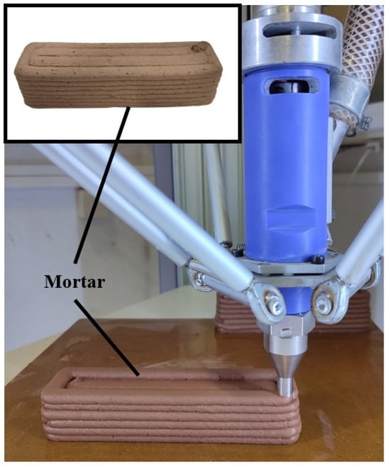
Figure 2.
Indicative images of the 3D printing process and the 3D-printed clay-based specimens.
2.2. Design Process
In the current study, the aforementioned prisms were redesigned embedding bioinspired lattice structures. These lattice structures are 3D-printed panels consisting of 2.5D architected materials with external dimensions of 160 mm × 40 mm × 2 mm. The developed panels are inserted in the prism structures during the LDM 3D printing process in every layer of the structure (5 mm). It is worth noting that in the actual process, the polymeric panels were immersed in the clay-based paste resulting in an actual clay clearance of 3 mm. In this paper, three entirely different 2.5D architected materials were selected in order to be evaluated for reinforcement of the clay-based prisms []. The first architected material was a 2.5D cubic grid, which is the simplest lattice structure yet the most commonly used in civil engineering applications []. The second chosen architected material was the 2.5D honeycomb-like lattice structure which is a bioinspired structure well-known for its remarkable mechanical behavior []. Finally, for the third architected material, a stochastic lattice structure was employed utilizing the bioinspired Voronoi design algorithm. The use of the Voronoi structure is a novel approach to reinforcement grids that has been known to increase interest in the evolution of additive manufacturing []. Figure 3 portrays indicative images of the selected 2.5D architected materials. It is worth noting that these architected materials were developed and designed utilizing nTopology design software (nTopology, New York, NY, USA).
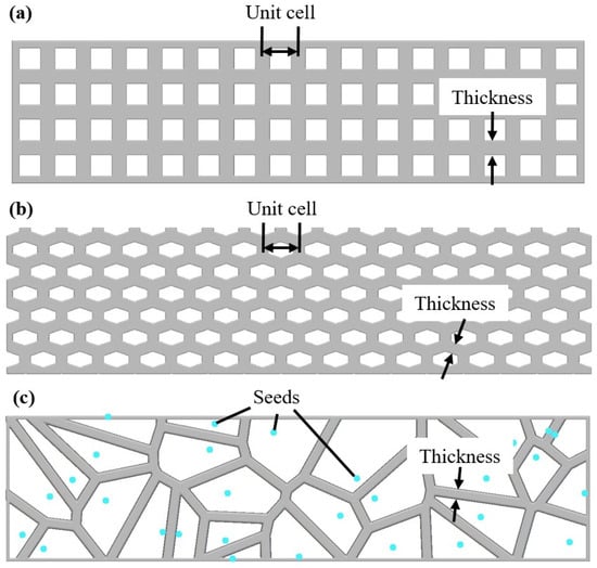
Figure 3.
Indicative images of the selected 2.5D architected material along with their main design features: (a) Cubic mesh, (b) Honeycomb mesh, and (c) Voronoi mesh.
The numerical evaluation of the lattice structure reinforcement was performed in three different relative densities for each selected architected material due to the influence of the size effect []. The size effect is the phenomenon that describes how the response of an architected material is degraded by the reduction in the relative density. This effect is intense for architected material below 60% relative density and obeys the following scaling law equations where Φsolid is the mechanical property of the construction material, Φlattice is the effective mechanical property for the lattice structure, and G and n are constants whose values depend on the construction material and the applied architected material [].
The three distinct relative densities for each employed lattice structure were chosen to be 30%, 50%, and 70%. Table 2 lists the values of the main design parameters, namely the strut thickness (ts), the unit cell length (l), and the seed distance (ls) for each architected material in order to achieve the desired relative densities. In addition, it is worth mentioning that each design panel has a height of 2 mm and the changes in the relative density of each structure were performed by modifying the strut thickness.

Table 2.
Design parameters for the lattice structures.
2.3. Finite Element Models
To numerically evaluate the developed clay-based prism reinforced by the aforementioned bioinspired lattice structures, Finite Element Models (FEMs) were developed, simulating the compressive and flexural response of each specimen. For this purpose, the static module of the ANSYS Workbench simulation platform (ANSYS, Inc., Canonsburg, PA, USA) was used. The first step in this process was the setup of material models. For the developed clay-based prism with polymeric reinforcement, two different material models were utilized, one for clay and one for the polymer. In addition, a bilinear isotropic hardening material model was deployed in order to simulate accurately both the elastic section but also a sufficient portion of the plastic section. For the clay-based material, the mechanical properties of Table 1 were used along with a Poisson ratio of 0.35. Regarding the polymeric lattice structure, the widely used PLA material was selected as construction material. Table 3 lists the main properties of 3D-printed PLA as they were derived from a previous study []. It is worth noting that the tangent modulus for both materials was set at a zero value, which is a legitimate assumption for these kinds of materials.

Table 3.
Main properties of 3D-printed PLA material [].
Furthermore, the composite prisms with clay-based and PLA materials were set to have bonded contact regions, a valid assumption due to the bonding properties of the solidified clay. Moreover, a mesh sensitivity analysis was performed to extract the minimum number of elements that could capture accurately the advanced morphology of the examined structure. This analysis was conducted based on the extracted equivalent von Mises stresses. The results of this analysis led to the utilization of tetrahedral elements with a minimum element size of 1 mm resulting in computation meshes between 400,000 and 500,000 elements. Regarding the loading conditions, there were two different loading scenarios, one for compression testing and one for three-point bending testing. Figure 4 graphically shows these two loading scenarios. For the three-point bending, the test configuration of a previous study was used [] to extract numerical results that will be comparable with future experimental results. This configuration had a length span of 90 mm, with two fixed cylinders of 30 mm diameter on the bottom side and one moving cylinder (probe) of 9.8 mm diameter on the upper side. It is worth mentioning that the execution of these finite element analyses (FEAs) was performed in 10 distinct steps in order to achieve smoother convergence and extract the mechanical response in each of these steps.
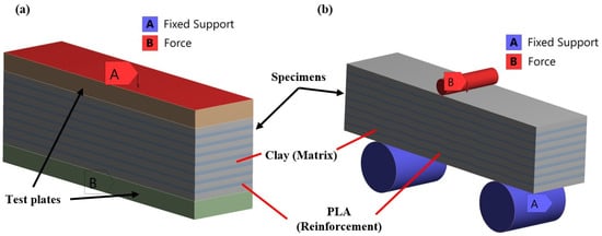
Figure 4.
Indicative images of the loading scenarios: (a) compression and (b) bending testing.
3. Results
3.1. Final Designs
Through the aforementioned design methodology, nine distinct designs of clay-based prisms reinforced with bioinspired lattice structures were produced into three different relative densities for each of the three selected architected materials. Figure 5 presents all the designed prisms highlighting both their matrix and their reinforcement.
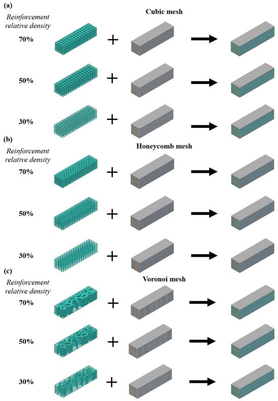
Figure 5.
Developed prism designs for: (a) cubic mesh, (b) honeycomb mesh, and (c) Voronoi mesh.
Regarding the as-designed density and weight of each prism, Table 4 presents the corresponding calculated values. In each of these nine different designs of reinforced clay-based prisms, there were seven panels of polymeric lattice reinforcement with a spacing of 3 mm. It is worth mentioning that the first and the last layers of the prism were designed at 4 mm following the result of a physical assembly of the reinforcement.

Table 4.
Weight and density of each designed prism specimen.
3.2. Numerical Evaluation
Utilizing the above-presented prism designs, FEAs were conducted for both compression and three-point bending testing. Through these FEAs, the compressive and flexural strengths were evaluated for each specimen coupled with the observed elastic modulus. Moreover, exploiting these results, the corresponding scaling laws were calculated, quantifying the mechanical behavior of these composite prisms for a sufficient range of relative density of the reinforcement structure. It is worth noting that for both loading scenarios, a pure clay-based prism was also simulated to use it as a benchmark for the developed structures.
Regarding the compressive behavior of the developed prisms, Table 5 lists the basic mechanical properties as they were derived from compression testing using FEAs. The acquired data showed that the clay-based prisms with the honeycomb reinforcement revealed the highest stiffness and strength, followed by ones with cubic reinforcement and the Voronoi structure. In addition, all examined reinforced prisms exhibited higher stiffness than the pure clay-based, which was expected due to the higher elastic modulus of the PLA material. In terms of strength, both the yield strength and the peak strength followed a similar trend, highlighting the honeycomb reinforcement as the best structure for this purpose, reaching a peak compressive force of around 17,000 N. Again, the reinforced prisms showed higher strength in general than the pure clay-based prisms. These results occur due to the high connectivity and more uniform stress distribution that are provided by the lattice structure reinforcement. The superior performance of the honeycomb reinforcement structure can be attributed to its morphology, which offers an exceptional strength-to-weight ratio, enhanced load distribution, and increased resistance to deformation and stress concentration. This geometry enables the honeycomb structure to more effectively and more uniformly bear and distribute applied forces compared to the other structures analyzed in this study.

Table 5.
Basic mechanical properties from compression testing.
The next step was the evaluation of the constants of the corresponding strength scaling law for the examined prisms. The scaling law parameters were calculated by applying a curve-fitted process for each corresponding power law. Table 6 presents the values of C and n for each employed lattice structure. Furthermore, Figure 6 portrays the scaling law curves for yield strength and peak strength, respectively. Through these formulations, a numerical tool is provided for each examined structure with which the strength of the developed composite can be easily evaluated for a wide range of relative density, i.e., from 10% to 70% of the applied reinforcement structure.

Table 6.
Scaling law parameters for the employed reinforcement structures.
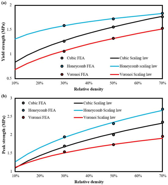
Figure 6.
Curve-fitted scaling laws of all examined reinforcement structures for: (a) yield strength and (b) peak strength.
It is worth noting that below 10% relative density the reinforcement structure reveals brittle behavior leading to the specimen’s failure. On the other hand, above the 70% relative density, a block of polymeric material is created, resulting in discrete regions of different materials. Regarding the trend of scaling laws, the observed behavior was an intense stretching-dominated behavior [], which was expected, due to the function of clay-based material as the bonding agent between the reinforcement structure, providing that way increasing connectivity between the elements of each structure. Finally, the curve-fitting process seems to be relatively accurate and reliable, achieving a coefficient of determination (R2) above 0.995.
Similar findings were observed in the bending testing via FEAs where reinforced clay-based prisms exhibited higher flexural strength, i.e., maximum force, than the pure clay-based prisms, as it is presented in Table 7. Again, honeycomb reinforcement revealed the highest flexural strength at 3.41 MPa, reaching a maximum bending strength of 1553 N. On the other hand, cubic and Voronoi reinforcement has similar strengths with cubic structure showing a little higher flexural strength in general.

Table 7.
Basic mechanical properties from bending testing.
In addition, in the bottom part of Table 7, the quantified constant of the scaling law for the flexural strength of each developed reinforced prism is depicted. Moreover, Figure 7 illustrates the corresponding curve-fitted scaling laws. These curves follow an almost linear trend highlighting the increased connectivity of the prism’s elements due to the existence of reinforcement structure. Again, it is obvious that the honeycomb reinforcement offers the best performance in terms of flexural strength with a substantial difference from the other reinforcements. It is also worth mentioning that the reliability and accuracy of the below-presented curve-fitted process reaches values of R2 above 0.995.
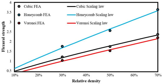
Figure 7.
Curve-fitted scaling laws of all examined reinforcement structures for flexural strength.
Finally, in Figure 8, indicative images of FEA results are depicted focusing separately on the two elements of the developed prism, namely the matrix and the reinforcement. More specifically, Figure 8 shows the equivalent von Mises stress distribution during the bending loading.
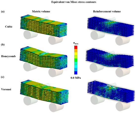
Figure 8.
Equivalent von Mises stress contours of 70% reinforced specimens for: (a) cubic, (b) honeycomb, and (c) Voronoi prisms.
As it was expected, the matrix disturbed the stress uniformly within the body of the entire structure. On the other hand, the reinforcement revealed a behavior, which is similar to the corresponding behavior of reinforced cement structures. In detail, the reinforcement layer near the load application point experiences compressive loads in contrast with the layer close to the fixation, which exhibited tensile loads due to the developed elastic deflection. This observed behavior is the one that led to an enhanced flexural response for the reinforced prism specimens.
4. Conclusions
In this study, a systemic approach incorporating computer aid and biomimetics is utilized for the development of 3D-printed clay-based composite mortar reinforced with advanced polymeric bioinspired lattice structures, namely, cubic grid, honeycombs, and Voronoi architected materials. The designed specimens were numerically examined under compression and bending loading and the corresponding mechanical performance was evaluated. Moreover, three different relative densities of reinforcement were employed in order to quantify the scaling laws for these complex structures, providing essential mathematical formulations to predict the mechanical response of a composite depending on the applied relative density. Through this series of computer-aided numerical analyses, the honeycomb reinforcement was highlighted as the one with the best mechanical performance in both compression and bending, followed by the cubic grid and the Voronoi structures. More specifically, honeycomb reinforcement at 70% relative density almost doubled the peak compression strength and tripled the flexural strength of the overall structure. These findings indicate that clay-based composite mortar reinforced with bio-based polymeric honeycomb, such as the PLA constructed, is capable of withstanding increased loads. Therefore, in the future, this type of structure can be further examined through experimental testing in order to verify its exceptional mechanical performance and pave the way for its integration into real-life applications. The ultimate objective of this study is to identify a more environmentally sustainable material that can potentially replace cement in construction, which is accompanied by a significant amount of CO2 emissions.
Author Contributions
Conceptualization, N.K. and S.P.; methodology, N.K. and S.P.; software, N.K.; validation, N.K.; formal analysis, N.K.; investigation, N.K. and S.P.; resources, E.M.P.; data curation, N.K. and S.P.; writing—original draft preparation, N.K. and S.P.; writing—review and editing, E.M.P.; visualization, N.K. and S.P.; supervision, E.M.P.; project administration, E.M.P.; funding acquisition, E.M.P. All authors have read and agreed to the published version of the manuscript.
Funding
This research received no external funding.
Institutional Review Board Statement
Not applicable.
Data Availability Statement
The raw data supporting the conclusions of this article will be made available by the authors on request.
Acknowledgments
The authors would like to thank the technical staff of Laboratory of Building Materials, School of Civil Engineering, Aristotle University of Thessaloniki, Greece, for providing the results from the mechanical testing of the 3D-printed specimens.
Conflicts of Interest
The authors declare no conflicts of interest.
References
- Simpson, T.W.; Williams, C.B.; Hripko, M. Preparing industry for additive manufacturing and its applications: Summary & recommendations from a National Science Foundation workshop. Addit. Manuf. 2017, 13, 166–178. [Google Scholar] [CrossRef]
- Hegab, H.; Khanna, N.; Monib, N.; Salem, A. Design for sustainable additive manufacturing: A review. Sustain. Mater. Technol. 2023, 35, e00576. [Google Scholar] [CrossRef]
- Pemas, S.; Gkiliopoulos, D.; Samiotaki, C.; Bikiaris, D.N.; Terzopoulou, Z.; Pechlivani, E.M. Valorization of Tomato Agricultural Waste for 3D-Printed Polymer Composites Based on Poly(lactic acid). Polymers 2024, 16, 1536. [Google Scholar] [CrossRef] [PubMed]
- Vafadar, A.; Guzzomi, F.; Rassau, A.; Hayward, K. Advances in Metal Additive Manufacturing: A Review of Common Processes, Industrial Applications, and Current Challenges. Appl. Sci. 2021, 11, 1213. [Google Scholar] [CrossRef]
- Labonnote, N.; Rønnquist, A.; Manum, B.; Rüther, P. Additive construction: State-of-the-art, challenges and opportunities. Autom. Constr. 2016, 72, 347–366. [Google Scholar] [CrossRef]
- Pechlivani, E.M.; Melidis, L.; Pemas, S.; Katakalos, K.; Tzovaras, D.; Konstantinidis, A.A. On the Effect of Volumetric Energy Density on the Characteristics of 3D-Printed Metals and Alloys. Metals 2023, 13, 1776. [Google Scholar] [CrossRef]
- Khanpara, P.; Tanwar, S. Additive Manufacturing: Concepts and Technologies. In A Roadmap to Industry 4.0: Smart Production, Sharp Business and Sustainable Development; Nayyar, A., Kumar, A., Eds.; Springer International Publishing: Cham, Switzerland, 2020; pp. 171–185. [Google Scholar] [CrossRef]
- Chen, X.; Chang-Richards, A.Y.; Pelosi, A.; Jia, Y.; Shen, X.; Siddiqui, M.K.; Yang, N. Implementation of technologies in the construction industry: A systematic review. Eng. Constr. Archit. Manag. 2021, 29, 3181–3209. [Google Scholar] [CrossRef]
- Perkins, I.; Skitmore, M. Three-dimensional printing in the construction industry: A review. Int. J. Constr. Manag. 2015, 15, 1–9. [Google Scholar] [CrossRef]
- Lim, S.; Buswell, R.; Le, T.; Austin, S.; Gibb, A.; Thorpe, T. Developments in construction-scale additive manufacturing processes. Autom. Constr. 2012, 21, 262–268. [Google Scholar] [CrossRef]
- Pan, Y.; Zhang, Y.; Zhang, D.; Song, Y. 3D printing in construction: State of the art and applications. Int. J. Adv. Manuf. Technol. 2021, 115, 1329–1348. [Google Scholar] [CrossRef]
- Zhao, J.; Tong, L.; Li, B.; Chen, T.; Wang, C.; Yang, G.; Zheng, Y. Eco-friendly geopolymer materials: A review of performance improvement, potential application and sustainability assessment. J. Clean. Prod. 2021, 307, 127085. [Google Scholar] [CrossRef]
- Bai, G.; Wang, L.; Ma, G.; Sanjayan, J.; Bai, M. 3D printing eco-friendly concrete containing under-utilised and waste solids as aggregates. Cem. Concr. Compos. 2021, 120, 104037. [Google Scholar] [CrossRef]
- Panda, B.; Tay, Y.; Paul, S.; Tan, M. Current challenges and future potential of 3D concrete printing. Mater. Werkst. 2018, 49, 666–673. [Google Scholar] [CrossRef]
- Rollakanti, C.R.; Prasad, C.V.S.R. Applications, performance, challenges and current progress of 3D concrete printing technologies as the future of sustainable construction—A state of the art review. Mater. Today Proc. 2022, 65, 995–1000. [Google Scholar] [CrossRef]
- Ahmed, G.H. A review of ‘3D concrete printing’: Materials and process characterization, economic considerations and environmental sustainability. J. Build. Eng. 2023, 66, 105863. [Google Scholar] [CrossRef]
- Zhang, J.; Wang, J.; Dong, S.; Yu, X.; Han, B. A review of the current progress and application of 3D printed concrete. Compos. Part A Appl. Sci. Manuf. 2019, 125, 105533. [Google Scholar] [CrossRef]
- Siddika, A.; Al Mamun, A.; Ferdous, W.; Saha, A.K.; Alyousef, R. 3D-printed concrete: Applications, performance, and challenges. J. Sustain. Cem.-Based Mater. 2020, 9, 127–164. [Google Scholar] [CrossRef]
- Gregory, M.; Hameedaldeen, S.A.; Intumu, L.M.; Spakousky, J.J.; Toms, J.B.; Steenhuis, H.J. 3D printing and disaster shelter costs. In Proceedings of the 2016 Portland International Conference on Management of Engineering and Technology (PICMET), Honolulu, HI, USA, 4–8 September 2016; pp. 712–720. [Google Scholar] [CrossRef]
- Subramanya, K.; Kermanshachi, S. Exploring Utilization of the 3D Printed Housing as Post-Disaster Temporary Shelter for Displaced People. American Society of Civil Engineers. In Construction Research Congress; American Society of Civil Engineers: Reston, VA, USA, 2022; pp. 594–605. [Google Scholar] [CrossRef]
- Khan, S.A.; Al Rashid, A.; Muhammad, J.; Ali, F.; Koc, M. 3D Printing Technology for Rapid Response to Climate Change: Challenges and Emergency Needs. Intell. Sustain. Manuf. 2024, 1, 10004. [Google Scholar] [CrossRef]
- Delavar, M.A.; Chen, H.; Sideris, P. Seismic Design Methodology for 3D Printed Concrete Buildings. Cityscape 2023, 25, 177–197. [Google Scholar]
- Ahmed, G.H.; Askandar, N.H.; Jumaa, G.B. A review of largescale 3DCP: Material characteristics, mix design, printing process, and reinforcement strategies. Structures 2022, 43, 508–532. [Google Scholar] [CrossRef]
- Freire, T.; Brun, F.; Mateus, A.; Gaspar, F. 3D Printing Technology in the Construction Industry. In Sustainability and Automation in Smart Constructions; Rodrigues, H., Gaspar, F., Fernandes, P., Mateus, A., Eds.; Springer International Publishing: Cham, Switzerland, 2021; pp. 157–167. [Google Scholar] [CrossRef]
- Xiao, J.; Zou, S.; Yu, Y.; Wang, Y.; Ding, T.; Zhu, Y.; Yu, J.; Li, S.; Duan, Z.; Wu, Y.; et al. 3D recycled mortar printing: System development, process design, material properties and on-site printing. J. Build. Eng. 2020, 32, 101779. [Google Scholar] [CrossRef]
- Moretti, M. WASP in the Edge of 3D Printing. In 3D Printing for Construction with Alternative Materials; Rangel, B., Guimarães, A.S., Lino, J., Santana, L., Eds.; Springer International Publishing: Cham, Switzerland, 2023; pp. 57–65. [Google Scholar] [CrossRef]
- Paul, S.C.; van Zijl, G.P.; Tan, M.J.; Gibson, I. A review of 3D concrete printing systems and materials properties: Current status and future research prospects. Rapid Prototyp. J. 2018, 24, 784–798. [Google Scholar] [CrossRef]
- Comminal, R.; da Silva, W.R.L.; Andersen, T.J.; Stang, H.; Spangenberg, J. Influence of Processing Parameters on the Layer Geometry in 3D Concrete Printing: Experiments and Modelling. In Second RILEM International Conference on Concrete and Digital Fabrication; Bos, F.P., Lucas, S.S., Wolfs, R.J.M., Salet, T.A.M., Eds.; Springer International Publishing: Cham, Switzerland, 2020; pp. 852–862. [Google Scholar] [CrossRef]
- Heidarnezhad, F.; Zhang, Q. Shotcrete based 3D concrete printing: State of art, challenges, and opportunities. Constr. Build. Mater. 2022, 323, 126545. [Google Scholar] [CrossRef]
- Kloft, H.; Krauss, H.-W.; Hack, N.; Herrmann, E.; Neudecker, S.; Varady, P.A.; Lowke, D. Influence of process parameters on the interlayer bond strength of concrete elements additive manufactured by Shotcrete 3D Printing (SC3DP). Cem. Concr. Res. 2020, 134, 106078. [Google Scholar] [CrossRef]
- Baduge, S.K.; Navaratnam, S.; Abu-Zidan, Y.; McCormack, T.; Nguyen, K.; Mendis, P.; Zhang, G.; Aye, L. Improving performance of additive manufactured (3D printed) concrete: A review on material mix design, processing, interlayer bonding, and reinforcing methods. Structures 2021, 29, 1597–1609. [Google Scholar] [CrossRef]
- Zhang, Y.; Zhu, Y.; Ren, Q.; He, B.; Jiang, Z.; Van Tittelboom, K.; De Schutter, G. Comparison of printability and mechanical properties of rigid and flexible fiber-reinforced 3D printed cement-based materials. Constr. Build. Mater. 2023, 400, 132750. [Google Scholar] [CrossRef]
- Liu, M.; Zhang, Q.; Tan, Z.; Wang, L.; Li, Z.; Ma, G. Investigation of steel wire mesh reinforcement method for 3D concrete printing. Archiv. Civ. Mech. Eng. 2021, 21, 24. [Google Scholar] [CrossRef]
- Marchment, T.; Sanjayan, J. Mesh reinforcing method for 3D Concrete Printing. Autom. Constr. 2020, 109, 102992. [Google Scholar] [CrossRef]
- Bos, F.P.; Ahmed, Z.Y.; Wolfs, R.J.M.; Salet, T.A.M. 3D Printing Concrete with Reinforcement. In High Tech Concrete: Where Technology and Engineering Meet; Hordijk, D.A., Luković, M., Eds.; Springer International Publishing: Cham, Switzerland, 2018; pp. 2484–2493. [Google Scholar] [CrossRef]
- Katzer, J.; Szatkiewicz, T. Effect of 3D Printed Spatial Reinforcement on Flexural Characteristics of Conventional Mortar. Materials 2020, 13, 3133. [Google Scholar] [CrossRef]
- Liu, M.; Wang, L.; Ma, G.; Li, W.; Zhou, Y. U-type steel wire mesh for the flexural performance enhancement of 3D printed concrete: A novel reinforcing approach. Mater. Lett. 2023, 331, 133429. [Google Scholar] [CrossRef]
- Pechlivani, E.M.; Papadimitriou, A.; Pemas, S.; Ntinas, G.; Tzovaras, D. IoT-Based Agro-Toolbox for Soil Analysis and Environmental Monitoring. Micromachines 2023, 14, 1698. [Google Scholar] [CrossRef]
- Pemas, S.; Xanthopoulou, E.; Terzopoulou, Z.; Konstantopoulos, G.; Bikiaris, D.N.; Kottaridi, C.; Tzovaras, D.; Pechlivani, E.M. Exploration of Methodologies for Developing Antimicrobial Fused Filament Fabrication Parts. Materials 2023, 16, 6937. [Google Scholar] [CrossRef] [PubMed]
- Baran, E.H.; Erbil, H.Y. Surface Modification of 3D Printed PLA Objects by Fused Deposition Modeling: A Review. Colloids Interfaces 2019, 3, 43. [Google Scholar] [CrossRef]
- Pemas, S.; Sougioultzi, K.; Kouroutzidou, C.; Stefanidou, M.; Konstantinidis, A.; Pechlivani, E.M. Enhancing Clay-Based 3D Printing Mortars with Polymeric Mesh Reinforcement Techniques. Polymers 2024. accepted. [Google Scholar]
- EN 1015-11:2019; Methods of Test for Mortar for Masonry—Part 11: Determination of Flexural and Compressive Strength of Hardened Mortar. iTeh Standards: Toronto, ON, Canada, 2019. Available online: https://standards.iteh.ai/catalog/standards/cen/14596d4c-119b-4a78-94e1-3fe481a29bde/en-1015-11-2019 (accessed on 25 June 2024).
- European Committee for Standardization. Methods of Test for Mortar for Masonry: Determination of Flexural and Compressive Strength of Hardened Mortar; European Committee for Standardization: Brussels, Belgium, 1999. [Google Scholar]
- Kladovasilakis, N.; Tsongas, K.; Karalekas, D.; Tzetzis, D. Architected Materials for Additive Manufacturing: A Comprehensive Review. Materials 2022, 15, 5919. [Google Scholar] [CrossRef] [PubMed]
- Kim, S.; Tang, X.; Chehab, G.R. Laboratory study of geogrid reinforcement in Portland cement concrete. In Pavement Cracking: Mechanisms, Modeling, Detection, Testing and Case Histories; Routledge and CRC Press, Taylor & Francis Group: Oxfordshire, UK, 2008; pp. 769–778. [Google Scholar] [CrossRef]
- Kladovasilakis, N.; Pechlivani, E.M.; Sfampa, I.K.; Tsongas, K.; Korlos, A.; David, C.; Tzovaras, D. Metal 3D-Printed Bioinspired Lattice Elevator Braking Pads for Enhanced Dynamic Friction Performance. Materials 2024, 17, 2765. [Google Scholar] [CrossRef]
- Efstathiadis, A.; Symeonidou, I.; Tsongas, K.; Tzimtzimis, E.K.; Tzetzis, D. 3D Printed Voronoi Structures Inspired by Paracentrotus lividus Shells. Designs 2023, 7, 113. [Google Scholar] [CrossRef]
- Kladovasilakis, N.; Tsongas, K.; Kostavelis, I.; Tzovaras, D.; Tzetzis, D. Effective mechanical properties of additive manufactured triply periodic minimal surfaces: Experimental and finite element study. Int. J. Adv. Manuf. Technol. 2022, 121, 7169–7189. [Google Scholar] [CrossRef]
- Kladovasilakis, N.; Tsongas, K.; Kostavelis, I.; Tzovaras, D.; Tzetzis, D. Effective Mechanical Properties of Additive Manufactured Strut-Lattice Structures: Experimental and Finite Element Study. Adv. Eng. Mater. 2022, 24, 2100879. [Google Scholar] [CrossRef]
- Kladovasilakis, N.; Charalampous, P.; Boumpakis, A.; Kontodina, T.; Tsongas, K.; Tzetzis, D.; Kostavelis, I.; Givissis, P.; Tzovaras, D. Development of biodegradable customized tibial scaffold with advanced architected materials utilizing additive manufacturing. J. Mech. Behav. Biomed. Mater. 2023, 141, 105796. [Google Scholar] [CrossRef]
Disclaimer/Publisher’s Note: The statements, opinions and data contained in all publications are solely those of the individual author(s) and contributor(s) and not of MDPI and/or the editor(s). MDPI and/or the editor(s) disclaim responsibility for any injury to people or property resulting from any ideas, methods, instructions or products referred to in the content. |
© 2024 by the authors. Licensee MDPI, Basel, Switzerland. This article is an open access article distributed under the terms and conditions of the Creative Commons Attribution (CC BY) license (https://creativecommons.org/licenses/by/4.0/).