Article

Investigating the Individual Performances of Coupled Superconducting Transmon Qubits

by
Halima Giovanna Ahmad
1,2,*,
Caleb Jordan
3,
Roald van den Boogaart
4,
Daan Waardenburg
4,
Christos Zachariadis
4,
Pasquale Mastrovito
1,
Asen Lyubenov Georgiev
1,†,
Domenico Montemurro
1,2,
Giovanni Piero Pepe
1,2,
Marten Arthers
4,
Alessandro Bruno
4,
Francesco Tafuri
1,5,
Oleg Mukhanov
3,
Marco Arzeo
6 and
Davide Massarotti
2,7
1
Dipartimento di Fisica “Ettore Pancini”, Università degli Studi di Napoli “Federico II”, c/o Complesso Monte Sant’Angelo, Via Cinthia, I-80126 Napoli, Italy
2
Consiglio Nazionale delle Ricerche—SuPerconducting and Other INnovative Materials and Devices Institute (SPIN), c/o Complesso Monte Sant’Angelo, Via Cinthia, I-80126 Napoli, Italy
3
SEEQC, Inc., 150 Clearbrook Rd Suite 170, Elmsford, NY 10523, USA
4
QuantWare, Elektronicaweg 10, 2628 XG Delft, The Netherlands
5
Consiglio Nazionale delle Ricerche-Istituto Nazionale di Ottica (CNR-INO), Largo Enrico Fermi 6, I-50125 Florence, Italy
6
SEEQC-EU, Strada Vicinale Cupa Cinthia, 21, I-80126 Napoli, Italy
7
Dipartimento di Ingegneria Elettrica e delle Tecnologie dell’Informazione, Università degli Studi di Napoli Federico II, I-80125 Napoli, Italy
*
Author to whom correspondence should be addressed.
Current address: Physikalisch-Technische Bundesanstalt (PTB), Bundesallee 100, D-38116 Braunschweig, Germany.
Condens. Matter 2023, 8(1), 29; https://doi.org/10.3390/condmat8010029
Submission received: 1 February 2023 / Revised: 14 March 2023 / Accepted: 16 March 2023 / Published: 21 March 2023

Abstract

:
The strong requirement for high-performing quantum computing led to intensive research on novel quantum platforms in the last decades. The circuital nature of Josephson-based quantum superconducting systems powerfully supports massive circuital freedom, which allowed for the implementation of a wide range of qubit designs, and an easy interface with the quantum processing unit. However, this unavoidably introduces a coupling with the environment, and thus to extra decoherence sources. Moreover, at the time of writing, control and readout protocols mainly use analogue microwave electronics, which limit the otherwise reasonable scalability in superconducting quantum circuits. Within the future perspective to improve scalability by integrating novel control energy-efficient superconducting electronics at the quantum stage in a multi-chip module, we report on an all-microwave characterization of a planar two-transmon qubits device, which involves state-of-the-art control pulses optimization. We demonstrate that the single-qubit average gate fidelity is mainly limited by the gate pulse duration and the quality of the optimization, and thus does not preclude the integration in novel hybrid quantum-classical superconducting devices.

1. Introduction

Superconducting Quantum processors are one of the most advanced platforms in the frame of both NISQ (Noisy-Intermediate-Scale-Quantum) [1] or Fault-Tolerant (FT) Quantum computing [2,3,4,5,6,7,8,9,10]. In order to efficiently solve application-specific problems for cryptography, pharmaceutical, quantum information and processing, both the paradigms require a large number of superconducting qubits [11,12], combined with long coherence times. This is not only meant for the implementation of several quantum gates, but most importantly, to get suitable and large single- and two-qubit gates fidelities [13].
Coherence times above hundreds of microseconds have been demonstrated for specific circuital designs, such as for transmon [14,15,16,17,18,19,20,21] or fluxonium qubits [22,23,24,25]. Within typical coherence times measured in these devices, it is in principle possible to reach the fault-tolerant error gate threshold p t h = 10 2 [2], corresponding to single qubit-gate fidelities of ~ 99 % , or even reach the gold standard of the three-nines, i.e., of the order of 99.9 % [2,26].
In order to solve complex quantum algorithms, we not only need high-performance single-qubit systems, but most importantly, the number of physical qubits in a superconducting Quantum Processing Unit (QPU) should increase by a few hundred, i.e., the state-of-the-art so far [27], to over 10 5 [26]. The possibility to engineer a QPU with such a number of physical qubits is the most challenging problem for quantum computing, also known as Input/Output (I/O) challenge.
Quantum controllers use analogue microwave-based control techniques to activate and readout the states of the QPU, which may overwhelm the cooling capacity of even the most powerful cryostats when increasing the number of qubits above ~400 [27,28]. Possible solutions to tackle the I/O problem are to employ analogue multiplexing [29,30], to minimize the heat load of wiring [28], or to introduce compact cryogenic circuitry [31,32,33,34,35,36,37]. These techniques are meant to optimize both the number and the volume of the microwave coaxial cabling at room temperature, as well as in the cryostat. Another approach is to search for novel hybrid Josephson devices to be integrated into superconducting quantum circuits in order to provide novel ways to scale superconducting QPU [38,39,40,41,42,43,44,45,46,47,48]. Finally, it has been proposed to integrate at the millikelvin stage both superconducting quantum processors and energy-efficient classical digital circuits [49,50,51,52], such as Single-Flux Quantum (SFQ) controllers [53,54,55] and Josephson-based readout circuits [56,57,58,59,60,61], into a quantum multi-chip module (qMCM) [62,63,64,65]. The request to separate the SFQ control electronics and the QPU in two different sub-modules comes from the need to mitigate quasiparticle dissipation arising in SFQ circuits [66]. Particularly relevant for SFQ controllers integration in the qMCM, the final goal is to replace analogue microwave control and readout signals supplied from room-temperature electronics via dedicated coaxial cables, with SFQ digital pulse patterns [67,68,69,70]. The expected reduced thermal load related to the replacement of RF-coaxial cabling when using an SFQ controller promise to unlock scaling to over 1000 qubits, but most importantly, it allows for low latency controller feedback [67,68,69,70], which is a fundamental prerequisite for FT quantum computing.
The realisation of qMCMs faces several engineering and physical challenges. As a matter of fact, the circuital parameters of the module hosting the quantum processor (quantum chip) and the superconducting electronics module (carrier chip) are strictly dependent on each other [65]. On the other hand, 3D-integration approaches allow fabrication and diagnosis of the qubits and the control modules separately [65]. In this work, we specifically focus on a preliminary all-microwave experimental characterization of a planar QPU subcircuit, which includes a pair of coupled transmon qubits. The testing protocol aims at the measurements of the circuital parameters, the relaxation and coherence times and Randomized Benchmarking single-qubit gate fidelities of the individual qubits in the QPU. We demonstrate that special care on the optimization of readout and control protocols is required in order to reach the theoretical best values for coherence and single-qubit fidelity in our device. We also demonstrate that we have successfully established a coupling between two qubits, which is a fundamental request for scalability and the implementation of two-qubit gates. By establishing and diagnosing experimentally the circuital parameters of the planar quantum chip, including the readout-qubit and qubit-qubit coupling factors, it is possible to simulate and predict the qMCM stack module performances. Therefore, the results reported in this work play a fundamental role in the future multi-qubit QPU integration in a qMCM stack module.

2. Results

In this work, we characterize two flux-tunable symmetric split-transmon qubits ( Q a and Q b ) integrated into a matrix of five transmon qubits, coupled by means of a high-frequency NbTiN bus. The nominal resonance frequency of bus coupling is 25–30 GHz.
Transmon qubits, proposed for the first time in Ref. [16], are modified Cooper-pair Boxes (CPBs), in which a shunt capacitor is added in parallel with the Josephson element to decrease the charging energy E c = e 2 / ( 2 C ) of the device, and therefore increase the ratio E J / E c [16]. In our samples, the Josephson element is a superconducting symmetric DC-SQUID loop with two Al/AlO x /Al Josephson junctions. By increasing the E J / E c , the sensitivity to charge-noise can be suppressed, thus making the transmon qubit protected against charge noise fluctuations compared to the CPB design [14,15,16,17,18,19,20,21].
Additional information on the sample circuital schematics and materials employed can be found in Section 3.

2.1. Read-Out Resonator and Qubit Spectroscopy

One-tone spectroscopy protocol as a function of the power of the resonators’ excitation signal provides the possibility to inspect the bare and the dressed (or low-photon) frequencies of the readout resonator. Additional information on the experimental setup can be found in Section 3. The transmission through the feedline shows the usual Lorentzian-like dip associated with the adsorption of photons in the readout resonator, which occurs on resonance with the readout frequency [71], as shown in Figure 1a,b for the readout resonators of Q a and Q b , respectively. At high-input power signals (red data points, specifically at 70 dBm on the device-under-test, corresponding to around 6–8 × 10 6 photons), the resonance frequency corresponds to the resonator bare state, and a positive shift χ l p of the frequency occurs in the low-photon regime (blue data points, specifically at 130 dBm on the device-under-test, corresponding to around tens of photons), demonstrating the coupling between the readout resonator and the qubit [72,73]. The low-photon shift at zero flux-field for the readout cavity of Q a is approximately χ a l p = ( 2.14 ± 0.05 ) MHz, while for Q b is χ b l p = ( 4.47 ± 0.05 ) MHz, where 50 kHz is a maximum error.
Dashed yellow and green curves in Figure 1 are the resonator fits in the high- and low-power regimes, from which we extract the intrinsic quality factor of the resonator Q i due to internal losses in the resonator, and the coupling quality factor Q c , which identifies the quality of the coupling with the environment and the external circuitry [71]. The total (loaded) quality factor Q l is given by Q l 1 = Q c 1 + Q i 1 , and is 7 × 10 3 for Q a and Q l = 9 × 10 3 for Q b . Moreover, as reported in Table 1, Q c is roughly one order of magnitudes smaller than Q i , thus suggesting that the resonators fall in the overcoupled regime.
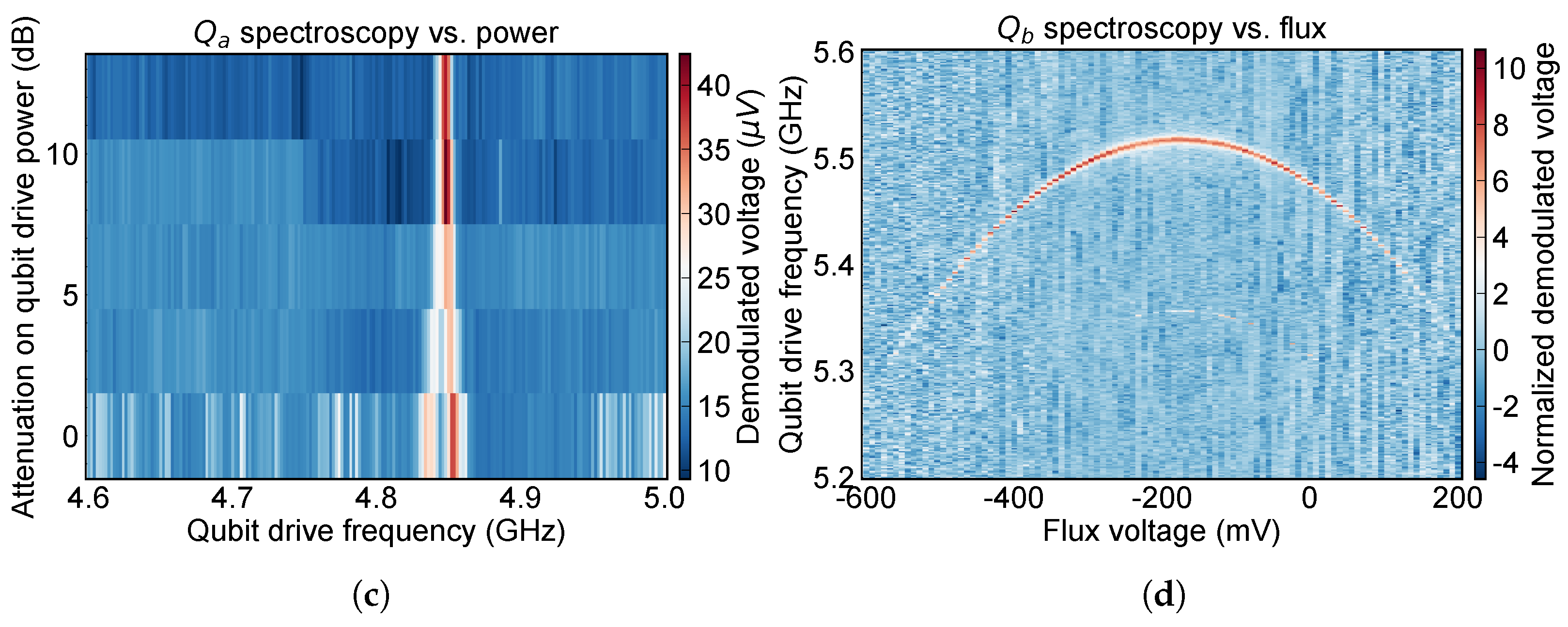
Two-tone spectroscopy measurements provide a first estimation of the qubit frequency [72]. In Figure 1c,d, we report an example of the two-tone pulsed spectroscopy for Q a and Q b , respectively. For the former, we show the dependence of the qubit resonance frequency ν 01 a as a function of the power of the qubit-drive pulse, which is here attenuated by means of a PXIe variable attenuator card. Additional information on the room-temperature experimental setup can be found in Section 3. The results in Figure 1c are acquired at the sweet spot (SS) of the qubit. For Q b , we report the dependence of the qubit resonance frequency ν 01 b as a function of the external flux. Qubit frequencies are ν 01 a = 4.8475 GHz and ν 01 b = 5.5167 GHz at the SS. Therefore, given the bare resonance frequencies of the readout resonators in Figure 1a,b, the qubit-readout frequency detuning Δ i = ν r i ν 01 i is, for Q a , Δ a = 2.65335 GHz and, for Q b , Δ b = 2.14443 GHz. The dispersive shit χ ranges from ( 1.35 ± 0.05 ) MHz to ( 0.91 ± 0.05 ) MHz for Q a and Q b , respectively, thus giving readout-qubit coupling factors of ( 112 ± 1 ) MHz and ( 88 ± 1 ) MHz [16,72]. All these parameters are also collected in Table 1.

2.2. Relaxation and Coherence Properties

In order to investigate the performances of superconducting transmon qubits, the experimental protocol requires an estimation of the relaxation time T 1 , and the coherence time T 2 and T 2 * of the qubits. Here, the * symbol conventionally indicates the T 2 value sensitive to quasi-static, low-frequency fluctuations that contribute to dephasing [72].
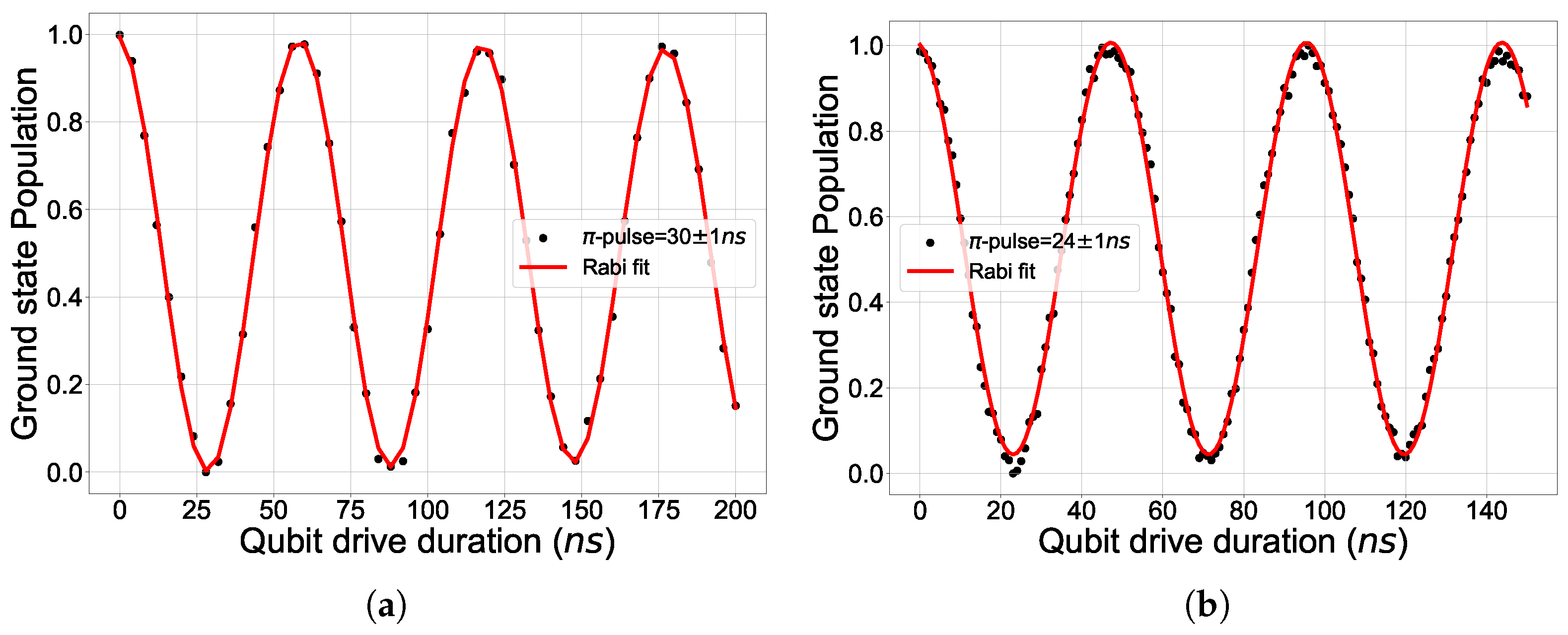
In the relaxation measurement, we first prepare the qubit in the excited state 1 , and we measure in time the free-evolution of the qubit state. In order to prepare the qubit state in 1 , we send a qubit-drive pulse on-resonance with the qubit frequency, and with the same duration as a π -pulse [73]. This parameter is experimentally accessed through Rabi oscillations measurements [73]. As an example, we show the experimental results obtained for qubit Q a and Q b in Figure 2, in which half the period of Rabi oscillations is the π -pulse.
For what concerns the study of decoherence processes in a superconducting transmon qubit, we use Hahn-Echo and Ramsey interferometry protocols. In the Hahn-Echo sequence, we prepare the qubit on the equator of the qubit Bloch sphere by sending a π / 2 qubit drive pulse, i.e., a pulse with half the amplitude of a π pulse. Then, we apply a refocus π -pulse, in order to perform a rotation around the z-axis. After that, we send another π / 2 -pulse, thus driving the qubit towards the 1 state. Finally, we measure the output signal after a waiting time that corresponds to the total Hahn-Echo sequence duration, which is gradually increased. Ramsey interferometry, instead, uses a π / 2 qubit drive pulse to prepare the qubit state on the equator of the Bloch sphere [72]. After a certain evolution time, in which dephasing effects can freely move the qubit on the equator, another π / 2 -pulse is sent, and then the qubit state is measured within the usual pulsed readout technique [73]. The experiment is repeated by increasing the total Ramsey sequence duration [73].
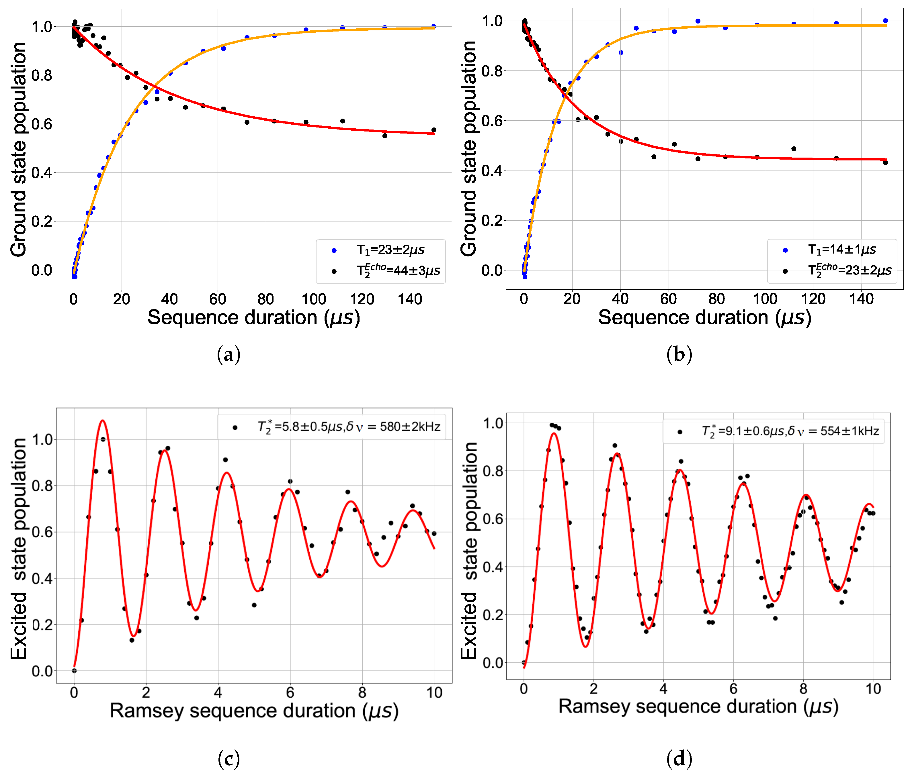
The results are reported in Figure 3 for qubit Q a and for Q b . Blue dots in Figure 3a,b correspond to the typical relaxation exponential decay in superconducting transmon qubits. The red curve is the exponential fit performed on the experimental data, which gives a relaxation time of T 1 a = 23 ± 2 μ s for Q a and T 1 b = 14 ± 1 μ s for Q b . The order of magnitude of the relaxation times is compatible with those found in the literature for state-of-the-art transmon qubit devices [72,74]. We here stress that the Hahn-Echo measurements (black dots in Figure 3a,b) and Ramsey oscillations in Figure 3c,d have been acquired before the optimization of π and π / 2 control pulses, thus leading to: (i) a revival of the ground state population at low sequence durations; (ii) a final ground state population deviating from the expected value of 0.5 . Even though dephasing effects due to unoptimized pulses in Echo and Ramsey sequences cannot be neglected in single-qubit gate fidelity measurements, at this stage of the characterization the main goal is to provide the relaxation and coherence times in order to have a first estimation of the theoretical maximum average single qubit gate fidelities.
In the limit of no detrimental dephasing of the qubit state, the coherence time should approach the theoretical limit T 2 2 T 1 [72]. The Hahn-Echo sequence allows us to mitigate low-frequency dephasing noise to a certain extent, as reported in Refs. [72,73]. Therefore, in the ideal-case scenario of complete noise-mitigation, the values of T 2 , E c h o should be consistent with the theoretical limit of 2 T 1 [72]. The exponential decay fit performed on the experimental Hahn-Echo data (orange curves in Figure 3a,b provides a Hahn-Echo decay time of T 2 , E c h o a = 44 ± 3 μ s for Q a and T 2 , E c h o b = 23 ± 2 μ s for Q b , which is fairly close to the theoretical 2 T 1 limit. Moreover, these values are larger than T 2 * obtained by the study of Ramsey oscillations, confirming that the Hahn-Echo sequence efficiently suppressed some low-frequency noise components, which cannot be neglected in the Ramsey experiment.
Finally, the coherence time of a superconducting transmon qubit contributes to the intrinsic limitation of the maximum single-qubit gate fidelity. Following Ref. [13], the single-qubit gate fidelity affected by uncorrelated energy relaxation with rate T 1 1 , and pure dephasing with rate T ϕ 1 = T 2 * 1 ( 2 T 1 ) 1 , reads as:
F = 1 1 3 τ T 1 1 T ϕ 1 ,
where τ is the mean gate sequence duration. For τ of the order of a few tens of nanoseconds, the single-qubit gate fidelity expected within the experimental T 1 and T 2 * are ~ 99.88 % for Q a , and of ~ 99.81 % for Q b , i.e., they are close to the three-nines 99.9 % golden standard. These values, in fact, promise one error in thousands of operations on the qubit, and are in line with average gate fidelity measured on state-of-the-art superconducting transmon qubits [6,74,75,76,77,78]. However, in order to reach the theoretical limit, an intensive optimization of the control pulses is required.

2.3. Control-Pulses Optimization

The experimental measurement of single-qubit gate fidelity is related to the error rate that occurs when multiple operations are performed on the qubit [13,79]. We here quantify the single-qubit gate fidelity by means of Randomized Benchmarking (RB) technique [76]. The RB protocol provides information on the single-qubit gate fidelity averaged over randomly chosen single-qubit Clifford gates [80]:
C = { I , X ± π , Y ± π , Z ± π , X ± π / 2 , Y ± π / 2 , Z ± π / 2 } .
Here, X , Y , Z identify the qubit rotation around a particular axis of the Bloch sphere, which is obtained by means of Pauli rotations, while the subscript specifies the rotation angle. Within this technique, we are able to quantify the quality of the qubit initial state preparation, and how well we are able to control and measure the qubit state after the application of a gate. Therefore, RB intrinsically includes the possibility to disentangle the effect of State Preparation And Measurement (SPAM) errors, which are typically introduced by the user if control pulses are not properly optimized from intrinsic depolarization errors [76].
The optimization of control pulses in superconducting qubits is of fundamental importance in order to evaluate the performances of single- and multi-qubit gates. As a matter of fact, high fidelities can be achieved by reducing SPAM errors, by carefully generating the correct drive pulse, in terms of their amplitude, shape, duration and frequency [76,81,82,83].
First of all, the RF I-Q mixers typically used for upconversion mechanisms may introduce an imbalance between the I and Q signal amplitudes [28,72]. Therefore, the calibration of π - and π / 2 -pulses is a fundamental step prior to fidelity measurements. This is achieved by: (i) preparing the qubit in the ground state; (ii) applying 2 π -pulses ( 4 π / 2 -pulses), thus driving the qubit again to the ground state, and then measuring the qubit state. The experiment is repeated for an increasing number of operations, and as a function of the relative amplitude of the I and Q signals. The optimal relative amplitude is obtained as the one for which the qubit returns to the ground state with the maximum amount of operations.
The same protocol can be used for the optimization of the π -pulse duration, while fine optimization of the qubit drive frequency is typically performed by Ramsey interferometry (Figure 4a). This measurement is very sensitive to the detuning between the qubit resonance and drive frequency. As a matter of fact, for drive frequencies ν d ν q the typical Ramsey fringes are observed, while for ν d = ν 01 a pure exponential decay of the qubit state is measured, with a decay rate related to qubit dephasing T 2 * [72]. Therefore, a useful way to identify the on-resonance qubit frequency is to set the qubit drive frequency to the centre of Ramsey fringes. An example in terms of the qubit population is shown in Figure 4a. For our device, qubit frequencies reported in Table 1 are consistent with the fine qubit drive frequency optimization by using the Ramsey protocol.
Finally, a fundamental role is also played by the control pulse shape [74,84]. As a matter of fact, spurious higher-order harmonics in the upconversion setup and overshoot (undershoot) in the control pulses may move the qubit outside the computational space (leakage errors), or introduce under- or over-rotations on the Bloch sphere (phase errors) [74,84]. In this work, we used the Derivative Reduction by Adiabatic Gate (DRAG) technique, proposed in Ref. [85], and largely employed in literature for the reduction of SPAM errors [75,76,78,86,87,88,89].
The DRAG technique corrects the pulse shape Ω ( t ) by introducing a term depending on the derivative of the control pulse d Ω ( t ) / d t [74],
Ω ( t ) = Ω ( t ) i α Δ d d t Ω ( t ) ,
where α is a scaling factor, and Δ is the difference between the transitions ν 12 and ν 01 , and can be further corrected by adding a detuning parameter δ f as [74]:
Δ = ν 12 ν 01 2 π δ f .
It has been demonstrated that the optimization of the scaling parameter α allows us to define a sweet spot for phase errors, while at the same time minimizing leakage errors [74]. Therefore, we focused on the optimization of the DRAG scaling parameter, keeping δ f = 0 .
We used the All-XY technique [84] to optimize the scaling factor α , which consists in sending to the qubit a sequence of X and Y single-qubit gates. A complete list of possible XY sequences is reported in Ref. [84]. For un-optimized control pulses, each XY sequence is characterized by a specific error syndrome sign, which can assume a positive or negative value. This corresponds to the overshoot or undershoot of the control pulses, respectively. Therefore, as proposed in Ref. [84], we have chosen to compare the readout voltage magnitude as a function of the DRAG scaling parameters for two XY sequences with opposite syndrome error signs, like X π Y π / 2 and Y π X π / 2 . For the former sequence, the dependence on the error accumulated within un-optimized control pulses causes an undershooting on the final arrival state, quantified in terms of an error ϵ , as depicted in Figure 4b. At the same time, the Y π X π / 2 sequence leads to an overshooting ( + ϵ ) on the final arrival state. A schematic representation of the experimental All-XY protocol in terms of drive and readout pulses is reported in Figure 4c. Intuitively, the readout voltage signal as a function of α has a positive slope for positive error sign, i.e., for overshoot signals, while it has a negative slope for negative error sign, i.e., for undershoot (Figure 4d). The optimal scaling factor is then found at the crossing between the two experimental curves [84].

2.4. Single-Qubit Gate Fidelities

The RB test provides an estimate of the average error rate of a qubit when applying sequences of random gates [82,90]. In the RB protocol, the qubit is first prepared in the ground state. Then, a sequence of Clifford gates, randomly chosen among the Clifford gate-set in Equation (2), followed by its inverse (or return gate) is applied. Finally, the qubit state is measured as a function of the number of Clifford gates.
In Figure 5a,b, we show the experimental results achieved on qubit Q a and Q b , respectively. The black dots are obtained by averaging 25 different repetitions, characterized by a different seed number for the pseudo-random generation of Clifford gates applied. The readout signal is averaged over 1000 demodulated digitized traces. The ground state population in RB measurements typically decays from maximum probability at zero Clifford gates applied to 0.5 . In our device, while for Q a this is consistent with the experimental outcomes, for Q b the arrival state deviates from the expected value (Figure 5). This is suggesting that for Q b further optimization of the 0 1 state calibration is required. Regardless of this behaviour, we can estimate the single-qubit gate fidelity, by using the fitting equation (red curve in Figure 5) [76]:
F ( N ) = A + B p N ,
where the fitting parameter A depends on the dimensionality of the system, the parameter B on the SPAM errors and p is also known as depolarization error. The depolarization error p for a single-qubit system depends on the average error committed per sequence r as:
r = 1 p 2 .
Therefore, we can calculate the average gate fidelity as F = 1 r , recovering for Q a an average single-qubit gate fidelity of F a = 99.42 ± 0.01 % , and for qubit Q b F b = 99.34 ± 0.02 % .

2.5. Evidence of Two-Qubit Coupling

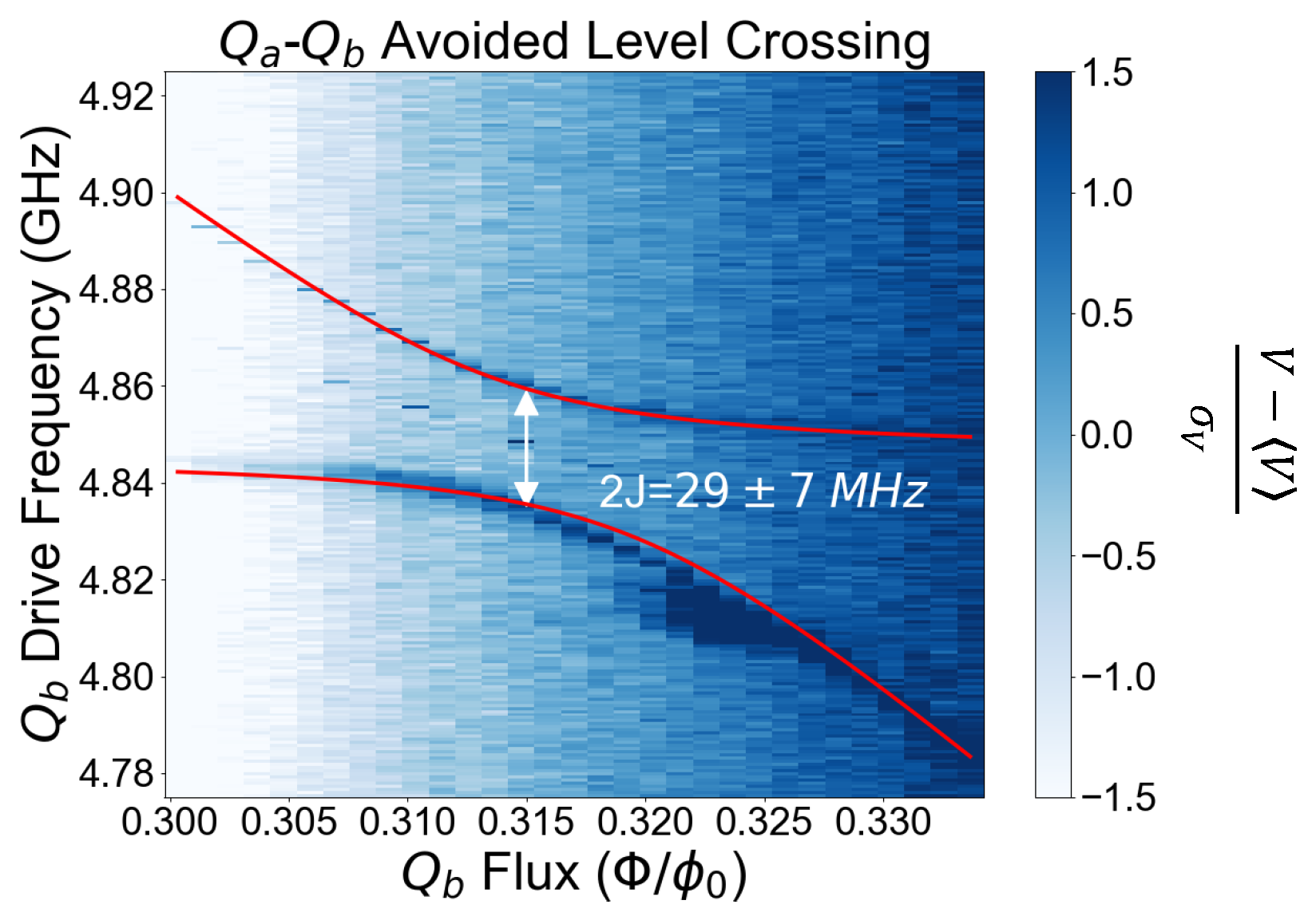
Within the future final goal of investigating the performances of coupled superconducting transmon qubits, and as a perspective to characterize multi-qubits gates performances on a scalable quantum processor, we here show preliminary results on the evidence of two-qubits coupling. In Figure 6, we report an experimental measurement of an Avoided Level Crossing (ALC) between Q a and Q b , which use a high-frequency resonator bus as a coupling element [91,92,93]. The colour scale identifies the normalized demodulated readout voltage phase signal measured within a two-tone spectroscopy technique on Q b , the highest frequency qubit. We then apply a flux bias to the SQUID in order to move the Q b frequency to be on resonance with Q a frequency. Close to the crossing point between the two frequencies, the appearance of a gap indicates the coupling between two-level system, with a strength J related to the amplitude of the gap [91,92,93,94]. Following the work in Refs. [91,92,94], we estimate a coupling energy through the symmetric and antisymmetric branches fit in Figure 6, and an energy gap 2 J = 29 ± 7 MHz. This value promises two-qubit i-SWAP gate time of t i S W A P 1 / ( 2 π ( 2 J ) ) 5 ns [86,93,95], and therefore two-qubit gate fidelities of the order of > 90 % [96,97].

3. Materials and Methods

A circuital schematic of our sample is reported in Figure 7a. The optical micrograph of a similar sample with four coupled transmon qubits, rather than five, is reported in Figure 7b. Chip dimension and general layout are the same as in the device analyzed in this work. Each qubit is equipped with a NbTiN readout superconducting CoPlanar-Waveguide (CPW) resonator, capacitively coupled to a common chip feedline in a notch-type geometry for simultaneous read-out of multiple qubits. The specifics on the NbTiN material are reported in Table 2. In order to guarantee optimal control of the qubits, each qubit is capacitively coupled to a dedicated drive line. Frequency tunability is guaranteed by a mutually inductively coupled dedicated flux line. Aluminium air bridges have been integrated in order to prevent the propagation of parasitic slot line modes in CPWs.
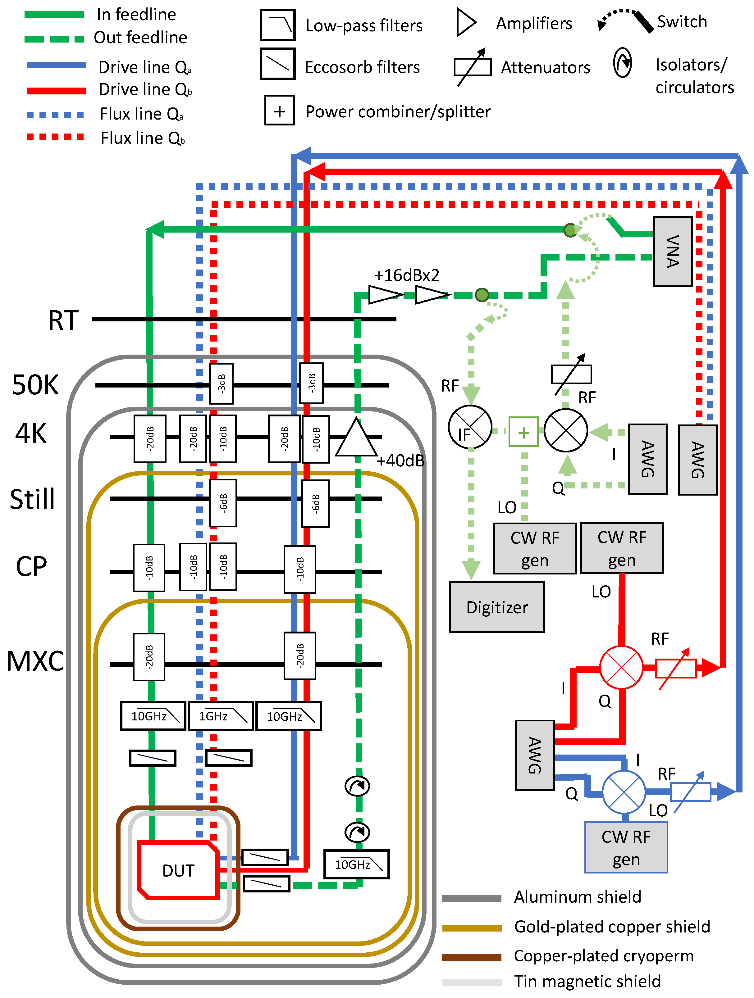
The sample is thermally and mechanically anchored at the mixing chamber (MXC) plate of a dry dilution refrigerator, and it is protected by infrared radiation and external magnetic fields by means of copper-plated cryo-perm screens (Figure 8). The temperature of the MXC plate is about 10 mK. Cryogenic lines for the input feedline and the drive lines are equipped with cryogenic attenuators, low-pass and eccosorb RF filters with 10 GHz, and > 12 GHz cutoff frequencies, respectively. The detailed attenuation scheme for drive and input lines is reported in Figure 8, and highlighted by straight blue or red lines for qubit Q a and Q b , respectively. The input line is represented by the green straight line. Cryogenic flux-bias lines are equipped with low-pass filters with 1 GHz cutoff frequency and 30 dB attenuation instead of 50 dB, to efficiently flux-tune the qubit frequency (see dashed blue (red) lines in Figure 8, for qubit Q a and Q b , respectively). The total attenuation scheme for the two lines share a 10–20 dB attenuator at the 4K-plate in order to reduce the current noise below the room-temperature Johnson-Nyquist noise [28]. The remaining attenuation is provided at the cold plate (CP) and the other plates in order to distribute the attenuators’ thermal load [28]. Finally, the cryogenic output line is equipped with a standard High-Electron Mobility Transistor (HEMT) amplifier at 4 K, a couple of cryogenic isolators (with a total isolation level of 40 dB) at the MXC plate and room-temperature RF-amplifiers.
The room-temperature electronics is a compact PXIe chassis able to both generate and measure Continuous Wave (CW) and Pulsed Wave (PW) RF signals. The former measurements use standard RF-signals generators and a Vector Network Analyzer (VNA), while the latter exploits the Heterodyne detection technique by means of Arbitrary Waveform Generators (AWGs) and I-Q mixers. The down-converted signal is measured by a PXIe digitizer with a sampling rate of 500 MSa/s. Such a signal is processed into real and imaginary quadratures, which can be also expressed in terms of amplitude and phase. The flux tuning is provided by a dedicated DC-offset voltage source.

4. Discussion and Concluding Remarks

The characterization and the study of a planar QPU with two split-transmon qubits coupled through a high-frequency bus resonator provided fundamental knowledge on the single-qubit gate fidelities and coherence times. Despite the relaxation and coherence times measured should allow for single-qubit gate fidelities close to 99.9 % , the measured ones deviate from the theoretical predictions of about 0.5 % . One possible explanation may be that the optimization protocols for the control pulses need to be improved. We must note that the control pulse optimization procedures hereby used must be performed iteratively in order to find the optimal control pulse parameters [82]. In this work, we have limited the iterative tune-up to a few iterations. However, automatic calibration/optimization of control pulses becomes fundamental for a fine optimization of the average gate fidelity, thus resulting in the possibility to achieve higher performance results. Moreover, we stress here that we may need to extend the optimization procedure to other parameters, such as the DRAG detuning parameter δ f , or the shape of the drive pulses. For these results, we used cosine-shaped drive pulses, but as a future perspective, it may be worth investigating the effect of the drive pulse shape on single-qubit gate fidelities [98,99,100]. Finally, we also point out that RB measurements reported have been performed by using π -pulses of the order of ~ 20 ns. We can not exclude that by increasing the speed of the implemented all-microwave gates we may achieve more favourable results.
As a future perspective, we aim in replacing analogue microwave-based control of the qubits with SFQ control electronics [54] by integrating the QPU subcircuit in a qMCM. SFQ voltage pulses with an amplitude of roughly 1 mV and duration of the order of 2 ps induce rotation on the Bloch sphere of an angle δ θ [54],
δ θ = C c ϕ 0 4 ω 01 E c e 2 ,
where C c is the SFQ controller-qubit coupling capacitance, and E c is the charging energy.
The results reported in this work represent a fundamental starting point in order to predict possible modifications on the relaxation and coherence times, and single-qubit gate fidelities, arising because of the coupling with an SFQ controller. As an example, we here discuss about the possibility to implement a flip-chip configuration [65].
In a flip-chip MCM configuration, signal lines, such as the feedline for multiplexed readout, the control and the flux lines, are located in the carrier chip, and separated from the quantum elements of the QPU. The distance between the carrier and the QPU induces variation in fundamental parameters, including the readout resonator and qubit frequencies, and therefore the dispersive detuning, the readout-qubit coupling, the qubit anharmonicity, and the control and readout quality factors. Specifically speaking, the charging energy E c in Equation (7) decreases compared with a planar architecture, as well as the qubit frequency, the readout and drive quality factors, as reported in Ref. [65].
Taking as an example the charging energy for qubit Q b , which can be inspected from the qubit spectroscopy measurement in Figure 1d, we observe that the two-photons assisted 0 2 transition occurs at 5.35 GHz at the SS, thus giving E c = 327 ± 1 MHz. In a flip-chip configuration, we will require to keep E c consistent with this value, given the fundamental request to maintain E J / E c suitable for a transmon configuration, i.e., of the order of 50–100 [16].
Other parameters that may be affected by the integration in a flip-chip qMCM module are the readout resonator frequency, the readout-qubit detuning, and the readout-qubit coupling, which typically increase when decreasing the distance between the carrier and the QPU, if compared to the single chip limit [65]. All these parameters play a fundamental role in the relaxation and coherence times.
Relaxation in superconducting transmon qubits is most likely related to spontaneous radiative decay due to both the Purcell effect in the readout resonators and the feedline, and the radiative decay in the coplanar waveguide lines for drive and control of the qubit [16]. From the readout-qubit frequency detuning Δ , the readout-qubit coupling g and the readout resonators quality factors Q l , the Purcell-limited relaxation time for the readout is
T 1 , P R O = Q l ν r Δ 2 g 2 .
The radiative losses in the drive lines induce a relaxation time that depends, instead, on the drive line-qubit coupling quality factor Q c d as
T 1 D = ν 01 Q c d ,
where Q c d is of the order of 10 6 10 7 [65]. Therefore, the total relaxation time is T 1 , P = ( T 1 D 1 + T 1 , P R O 1 ) .
Another possible noise source that may limit relaxation times is due to dielectric losses in the materials composing the device, which gives a relaxation time T 1 d i e [101]:
T 1 d i e = 1 ν 01 i p i / Q i + Γ 0 ,
where Q i = 1 / tan δ i is the quality factor of the i-th material, characterized by the loss-tangent tan δ i , and the participation ratio p i , defined as the fraction of electric field energy stored within the volume of this material, and Γ 0 is the relaxation rate induced by non-dielectric channels [101].
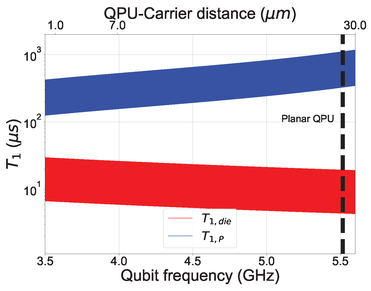
For what concerns the device analyzed in this work, we estimated the relaxation time due to Purcell and radiative losses by using the parameters experimentally measured (Table 1), and the relaxation time due to dielectric losses with the Python package scqubits [102,103], where we set the capacitive quality factor to 0.5 × 10 6 and the temperature to the nominal MXC temperature of 10 mK. We stress that the capacitive quality factor used represents a rough estimation of dielectric losses induced decay, given by the relation Q = ν 01 T 1 . With these parameters, the estimated total relaxation time due to Purcell and radiative decay through the drive lines is of the order of 700 μ s, which is one order of magnitude larger compared to the experimental ones. The relaxation time due to dielectric losses, instead, is consistent with measured T 1 , thus possibly being the most important limitation to T 1 in our devices.
Let us now consider fixing the circuital design parameters of the QPU in a multi-chip module to the experimental ones measured in the planar single-chip version. Compared to the single-chip case, corresponding to an infinite separation between the two modules, both Purcell and radiative losses through the drive lines, and dielectric relaxation times are expected to depend on the distance between the carrier and the QPU d [65]. This is due to the fact that in a flip-chip configuration, all the capacitive elements in the device will depend on d [65]. Specifically, as reported in the Supplementary material of Ref. [65], the qubit self-capacitance, the drive coupling capacitance and the resonator capacitance increase when decreasing d. Therefore, the qubit frequency will effectively decrease with d, thus decreasing the radiative relaxation time for the drive lines T 1 D and increasing the relaxation time due to dielectric losses T 1 , d i e [65]. However, even though the resonator capacitance increases when decreasing the inter-chip distance, in a flip-chip configuration the most important effect on the resonator frequency is given by the resonator inductance, which instead tends to decrease as a function of d [65]. This effectively increases the readout resonator frequency by decreasing d. As a consequence, the behaviour of the total Purcell relaxation time as a function of d is not trivial and takes into account the interplay between all these fundamental parameters [65]. In order to perform a comparison between the Purcell and radiative losses through the drive lines, and dielectric losses in a flip-chip qMCM, in Figure 9 we report a simulation of the expected T 1 for the two noise sources as a function of the qubit frequency, which is changed according to its dependence on the distance between the QPU and the carrier. As a reference, we have used Q b parameters (Table 1). In this scenario, while the relaxation time due to radiative losses in the drive lines and Purcell effect will decrease in the qMCM regime, the dielectric losses will likely still dominate the relaxation (Figure 9).
This suggests that we do not expect to worsen the relaxation time when integrating the QPU in a flip-chip qMCM configuration.
Additionally to the possibility to implement a flip-chip MCM configuration, it is not excluded to search for novel modular configurations [104]. DC to microwave low-losses connectivity can be provided by vertical superconducting vias through the QPU substrate. This ensures a separation between the SFQ-controller chip and the QPU, while at the same time preserving the circuit parameters, which are instead dependent on the MCM gap in the flip-chip configuration [104].
In conclusion, we have reported on an experimental investigation of single-qubit coherence and fidelity in a superconducting transmon planar QPU architecture for future integration in an MCM configuration. The reported results provide insightful predictions on the possibility to replace analogue microwave control pulses with SFQ electronics.

Author Contributions

Conceptualization, H.G.A., M.A. (Marco Arzeo) and D.M. (Davide Massarotti); methodology, M.A. (Marco Arzeo); software, M.A. (Marco Arzeo) and A.L.G.; validation, H.G.A. and M.A. (Marco Arzeo); formal analysis, H.G.A., M.A. (Marco Arzeo), A.L.G. and P.M.; investigation, H.G.A., M.A. (Marco Arzeo) and A.L.G.; resources, C.J., R.v.d.B., D.W. and C.Z.; data curation, H.G.A., M.A. (Marco Arzeo) and D.M. (Davide Massarotti); writing—original draft preparation, H.G.A., M.A. (Marco Arzeo) and D.M. (Davide Massarotti); writing—review and editing, H.G.A., M.A. (Marco Arzeo), D.M. (Davide Massarotti), D.M. (Domenico Montemurro), and O.M.; visualization, H.G.A.; supervision, M.A. (Marco Arzeo) and D.M. (Davide Massarotti); funding acquisition, M.A. (Marco Arzeo), D.M. (Davide Massarotti), M.A. (Marten Arthers), A.B., F.T. and G.P.P. All authors have read and agreed to the published version of the manuscript.

Funding

The work was supported by the project “SFQ4QPU”, Eurostars 115636, Code: ES21COD15_00043, the project “SQUAD—On-chip control and advanced read-out for superconducting qubit arrays,” Programma STAR PLUS 2020, Finanziamento della Ricerca di Ateneo, University of Napoli Federico II, the project SuperLink - Superconducting quantum-classical linked computing systems, call QuantERA2 ERANET COFUND, CUP B53C22003320005, the PNRRMUR project PE0000023-NQSTI and the PNRR MUR project CN_00000013 -ICSC.

Institutional Review Board Statement

Not applicable.

Informed Consent Statement

Not appicable.

Data Availability Statement

Due to confidentiality agreements, the data supporting this study can only be made available to personnel subject to a non-disclosure agreement.

Acknowledgments

H.G.A., D.M. (Davide Massarotti) and F.T. thank SUPERQUMAP project (COST Action CA21144).

Conflicts of Interest

The authors declare no conflict of interest.

Sample Availability

Due to their proprietary nature, samples cannot be made publicly available.

References

  1. Preskill, J. Quantum Computing in the NISQ era and beyond. Quantum 2018, 2, 79. [Google Scholar] [CrossRef]
  2. Fowler, A.G.; Mariantoni, M.; Martinis, J.M.; Cleland, A.N. Surface codes: Towards practical large-scale quantum computation. Phys. Rev. A 2012, 86, 032324. [Google Scholar] [CrossRef] [Green Version]
  3. Gambetta, J.M.; Chow, J.M.; Steffen, M. Building logical qubits in a superconducting quantum computing system. NPJ Quantum Inf. 2017, 3, 2. [Google Scholar] [CrossRef] [Green Version]
  4. Versluis, R.; Poletto, S.; Khammassi, N.; Tarasinski, B.; Haider, N.; Michalak, D.J.; Bruno, A.; Bertels, K.; DiCarlo, L. Scalable Quantum Circuit and Control for a Superconducting Surface Code. Phys. Rev. Appl. 2017, 8, 034021. [Google Scholar] [CrossRef] [Green Version]
  5. Campbell, E.T.; Terhal, B.M.; Vuillot, C. Roads towards fault-tolerant universal quantum computation. Nature 2017, 549, 172–179. [Google Scholar] [CrossRef] [Green Version]
  6. Egan, L.; Debroy, D.M.; Noel, C.; Risinger, A.; Zhu, D.; Biswas, D.; Newman, M.; Li, M.; Brown, K.R.; Cetina, M.; et al. Fault-tolerant control of an error-corrected qubit. Nature 2021, 598, 281–286. [Google Scholar] [CrossRef]
  7. Krinner, S.; Lacroix, N.; Remm, A.; Di Paolo, A.; Genois, E.; Leroux, C.; Hellings, C.; Lazar, S.; Swiadek, F.; Herrmann, J.; et al. Realizing repeated quantum error correction in a distance-three surface code. Nature 2022, 605, 669–674. [Google Scholar] [CrossRef]
  8. Webster, P.; Vasmer, M.; Scruby, T.R.; Bartlett, S.D. Universal fault-tolerant quantum computing with stabilizer codes. Phys. Rev. Res. 2022, 4, 013092. [Google Scholar] [CrossRef]
  9. Zhao, Y.; Ye, Y.; Huang, H.L.; Zhang, Y.; Wu, D.; Guan, H.; Zhu, Q.; Wei, Z.; He, T.; Cao, S.; et al. Realization of an Error-Correcting Surface Code with Superconducting Qubits. Phys. Rev. Lett. 2022, 129, 030501. [Google Scholar] [CrossRef]
  10. Marques, J.F.; Varbanov, B.M.; Moreira, M.S.; Ali, H.; Muthusubramanian, N.; Zachariadis, C.; Battistel, F.; Beekman, M.; Haider, N.; Vlothuizen, W.; et al. Logical-qubit operations in an error-detecting surface code. Nat. Phys. 2022, 18, 80–86. [Google Scholar] [CrossRef]
  11. Koch, D.; Torrance, A.; Kinghorn, D.; Patel, S.; Wessing, L.; Alsing, P.M. Simulating Quantum Algorithms Using Fidelity and Coherence Time as Principle Models for Error. arXiv 2019, arXiv:1908.04229. [Google Scholar]
  12. Bravyi, S.; Dial, O.; Gambetta, J.M.; Gil, D.; Nazario, Z. The future of quantum computing with superconducting qubits. J. Appl. Phys. 2022, 132, 160902. [Google Scholar] [CrossRef]
  13. Abad, T.; Fernández-Pendás, J.; Frisk Kockum, A.; Johansson, G. Universal Fidelity Reduction of Quantum Operations from Weak Dissipation. Phys. Rev. Lett. 2022, 129, 150504. [Google Scholar] [CrossRef] [PubMed]
  14. Wallraff, A.; Schuster, D.I.; Blais, A.; Frunzio, L.; Huang, R.S.; Majer, J.; Kumar, S.; Girvin, S.M.; Schoelkopf, R.J. Strong coupling of a single photon to a superconducting qubit using circuit quantum electrodynamics. Nature 2004, 431, 162–167. [Google Scholar] [CrossRef] [Green Version]
  15. Blais, A.; Huang, R.S.; Wallraff, A.; Girvin, S.M.; Schoelkopf, R.J. Cavity quantum electrodynamics for superconducting electrical circuits: An architecture for quantum computation. Phys. Rev. A 2004, 69, 062320. [Google Scholar] [CrossRef] [Green Version]
  16. Koch, J.; Yu, T.M.; Gambetta, J.; Houck, A.A.; Schuster, D.I.; Majer, J.; Blais, A.; Devoret, M.H.; Girvin, S.M.; Schoelkopf, R.J. Charge-insensitive qubit design derived from the Cooper pair box. Phys. Rev. A 2007, 76, 042319. [Google Scholar] [CrossRef] [Green Version]
  17. Oliver, W.D.; Welander, P.B. Materials in superconducting quantum bits. MRS Bull. 2013, 38, 816–825. [Google Scholar] [CrossRef] [Green Version]
  18. Lee, K.H.; Chakram, S.; Kim, S.E.; Mujid, F.; Ray, A.; Gao, H.; Park, C.; Zhong, Y.; Muller, D.A.; Schuster, D.I.; et al. Two-Dimensional Material Tunnel Barrier for Josephson Junctions and Superconducting Qubits. Nano Lett. 2019, 19, 8287–8293. [Google Scholar] [CrossRef]
  19. Place, A.P.M.; Rodgers, L.V.H.; Mundada, P.; Smitham, B.M.; Fitzpatrick, M.; Leng, Z.; Premkumar, A.; Bryon, J.; Vrajitoarea, A.; Sussman, S.; et al. New material platform for superconducting transmon qubits with coherence times exceeding 0.3 milliseconds. Nat. Commun. 2021, 12, 1779. [Google Scholar] [CrossRef]
  20. Blais, A.; Grimsmo, A.L.; Girvin, S.M.; Wallraff, A. Circuit quantum electrodynamics. Rev. Mod. Phys. 2021, 93, 025005. [Google Scholar] [CrossRef]
  21. Wang, C.; Li, X.; Xu, H.; Li, Z.; Wang, J.; Yang, Z.; Mi, Z.; Liang, X.; Su, T.; Yang, C.; et al. Towards practical quantum computers: Transmon qubit with a lifetime approaching 0.5 milliseconds. NPJ Quantum Inf. 2022, 8, 3. [Google Scholar] [CrossRef]
  22. Manucharyan, V.E.; Koch, J.; Glazman, L.I.; Devoret, M.H. Fluxonium: Single Cooper-Pair Circuit Free of Charge Offsets. Science 2009, 326, 113–116. [Google Scholar] [CrossRef] [PubMed] [Green Version]
  23. Nguyen, L.B.; Lin, Y.H.; Somoroff, A.; Mencia, R.; Grabon, N.; Manucharyan, V.E. High-Coherence Fluxonium Qubit. Phys. Rev. X 2019, 9, 041041. [Google Scholar] [CrossRef] [Green Version]
  24. Somoroff, A.; Ficheux, Q.; Mencia, R.A.; Xiong, H.; Kuzmin, R.V.; Manucharyan, V.E. Millisecond coherence in a superconducting qubit. arXiv 2021, arXiv:2103.08578. [Google Scholar]
  25. Dogan, E.; Rosenstock, D.; Guevel, L.L.; Xiong, H.; Mencia, R.A.; Somoroff, A.; Nesterov, K.N.; Vavilov, M.G.; Manucharyan, V.E.; Wang, C. Demonstration of the Two-Fluxonium Cross-Resonance Gate. arXiv 2022, arXiv:2204.11829. [Google Scholar]
  26. Sevilla, J.; Riedel, C.J. Forecasting timelines of quantum computing. arXiv 2020, arXiv:2009.05045. [Google Scholar]
  27. IBM Unveils 400 Qubit-Plus Quantum Processor and Next-Generation IBM Quantum System Two. 2022. Available online: https://newsroom.ibm.com/2022-11-09-IBM-Unveils-400-Qubit-Plus-Quantum-Processor-and-Next-Generation-IBM-Quantum-System-Two (accessed on 1 February 2023).
  28. Krinner, S.; Storz, S.; Kurpiers, P.; Magnard, P.; Heinsoo, J.; Keller, R.; Lütolf, J.; Eichler, C.; Wallraff, A. Engineering cryogenic setups for 100-qubit scale superconducting circuit systems. EPJ Quantum Technol. 2019, 6, 2. [Google Scholar] [CrossRef] [Green Version]
  29. George, R.E.; Senior, J.; Saira, O.P.; Pekola, J.P.; de Graaf, S.E.; Lindström, T.; Pashkin, Y.A. Multiplexing Superconducting Qubit Circuit for Single Microwave Photon Generation. J. Low Temp. Phys. 2017, 189, 60–75. [Google Scholar] [CrossRef] [Green Version]
  30. Shan, Z.; Zhu, Y.; Zhao, B. A high-performance compilation strategy for multiplexing quantum control architecture. Sci. Rep. 2022, 12, 7132. [Google Scholar] [CrossRef]
  31. Braginski, A.I. Superconductor Electronics: Status and Outlook. J. Supercond. Nov. Magn. 2019, 32, 23–44. [Google Scholar] [CrossRef] [Green Version]
  32. Lin, J.; Liang, F.T.; Xu, Y.; Sun, L.H.; Guo, C.; Liao, S.K.; Peng, C.Z. Scalable and customizable arbitrary waveform generator for superconducting quantum computing. AIP Adv. 2019, 9, 115309. [Google Scholar] [CrossRef]
  33. Pauka, S.J.; Das, K.; Kalra, R.; Moini, A.; Yang, Y.; Trainer, M.; Bousquet, A.; Cantaloube, C.; Dick, N.; Gardner, G.C.; et al. A cryogenic CMOS chip for generating control signals for multiple qubits. Nat. Electron. 2021, 4, 64–70. [Google Scholar] [CrossRef]
  34. Potočnik, A.; Brebels, S.; Verjauw, J.; Acharya, R.; Grill, A.; Wan, D.; Mongillo, M.; Li, R.; Ivanov, T.; Winckel, S.V.; et al. Millikelvin temperature cryo-CMOS multiplexer for scalable quantum device characterisation. Quantum Sci. Technol. 2021, 7, 015004. [Google Scholar] [CrossRef]
  35. Parker, M. Controlling qubits with cryogenic devices. Nat. Electron. 2022, 5, 125. [Google Scholar] [CrossRef]
  36. Howe, L.; Castellanos-Beltran, M.A.; Sirois, A.J.; Olaya, D.; Biesecker, J.; Dresselhaus, P.D.; Benz, S.P.; Hopkins, P.F. Digital Control of a Superconducting Qubit Using a Josephson Pulse Generator at 3 K. PRX Quantum 2022, 3, 010350. [Google Scholar] [CrossRef]
  37. Lecocq, F.; Quinlan, F.; Cicak, K.; Aumentado, J.; Diddams, S.A.; Teufel, J.D. Control and readout of a superconducting qubit using a photonic link. Nature 2021, 591, 575–579. [Google Scholar] [CrossRef]
  38. Larsen, T.W.; Petersson, K.D.; Kuemmeth, F.; Jespersen, T.S.; Krogstrup, P.; Nygård, J.; Marcus, C.M. Semiconductor-Nanowire-Based Superconducting Qubit. Phys. Rev. Lett. 2015, 115, 127001. [Google Scholar] [CrossRef] [Green Version]
  39. de Lange, G.; van Heck, B.; Bruno, A.; van Woerkom, D.J.; Geresdi, A.; Plissard, S.R.; Bakkers, E.P.A.M.; Akhmerov, A.R.; DiCarlo, L. Realization of Microwave Quantum Circuits Using Hybrid Superconducting-Semiconducting Nanowire Josephson Elements. Phys. Rev. Lett. 2015, 115, 127002. [Google Scholar] [CrossRef] [Green Version]
  40. Wiedenmann, J.; Bocquillon, E.; Deacon, R.S.; Hartinger, S.; Herrmann, O.; Klapwijk, T.M.; Maier, L.; Ames, C.; Brüne, C.; Gould, C.; et al. 4π-periodic Josephson supercurrent in HgTe-based topological Josephson junctions. Nat. Commun. 2016, 7, 10303. [Google Scholar] [CrossRef] [Green Version]
  41. Manousakis, J.; Altland, A.; Bagrets, D.; Egger, R.; Ando, Y. Majorana qubits in a topological insulator nanoribbon architecture. Phys. Rev. B 2017, 95, 165424. [Google Scholar] [CrossRef] [Green Version]
  42. Karzig, T.; Knapp, C.; Lutchyn, R.M.; Bonderson, P.; Hastings, M.B.; Nayak, C.; Alicea, J.; Flensberg, K.; Plugge, S.; Oreg, Y.; et al. Scalable designs for quasiparticle-poisoning-protected topological quantum computation with Majorana zero modes. Phys. Rev. B 2017, 95, 235305. [Google Scholar] [CrossRef] [Green Version]
  43. Gül, Ö.; Zhang, H.; Bommer, J.D.S.; de Moor, M.W.A.; Car, D.; Plissard, S.R.; Bakkers, E.P.A.M.; Geresdi, A.; Watanabe, K.; Taniguchi, T.; et al. Ballistic Majorana nanowire devices. Nat. Nanotechnol. 2018, 13, 192–197. [Google Scholar] [CrossRef] [PubMed]
  44. Kroll, J.G.; Uilhoorn, W.; van der Enden, K.L.; de Jong, D.; Watanabe, K.; Taniguchi, T.; Goswami, S.; Cassidy, M.C.; Kouwenhoven, L.P. Magnetic field compatible circuit quantum electrodynamics with graphene Josephson junctions. Nat. Commun. 2018, 9, 4615. [Google Scholar] [CrossRef] [PubMed] [Green Version]
  45. Casparis, L.; Connolly, M.R.; Kjaergaard, M.; Pearson, N.J.; Kringhøj, A.; Larsen, T.W.; Kuemmeth, F.; Wang, T.; Thomas, C.; Gronin, S.; et al. Superconducting gatemon qubit based on a proximitized two-dimensional electron gas. Nat. Nanotechnol. 2018, 13, 915–919. [Google Scholar] [CrossRef] [PubMed] [Green Version]
  46. Kunakova, G.; Surendran, A.P.; Montemurro, D.; Salvato, M.; Golubev, D.; Andzane, J.; Erts, D.; Bauch, T.; Lombardi, F. Topological insulator nanoribbon Josephson junctions: Evidence for size effects in transport properties. J. Appl. Phys. 2020, 128, 194304. [Google Scholar] [CrossRef]
  47. Ahmad, H.G.; Minutillo, M.; Capecelatro, R.; Pal, A.; Caruso, R.; Passarelli, G.; Blamire, M.G.; Tafuri, F.; Lucignano, P.; Massarotti, D. Coexistence and tuning of spin-singlet and triplet transport in spin-filter Josephson junctions. Commun. Phys. 2022, 5, 2. [Google Scholar] [CrossRef]
  48. Ahmad, H.G.; Brosco, V.; Miano, A.; Di Palma, L.; Arzeo, M.; Montemurro, D.; Lucignano, P.; Pepe, G.P.; Tafuri, F.; Fazio, R.; et al. Hybrid ferromagnetic transmon qubit: Circuit design, feasibility, and detection protocols for magnetic fluctuations. Phys. Rev. B 2022, 105, 214522. [Google Scholar] [CrossRef]
  49. Likharev, K.K.; Semenov, V.K. RSFQ logic/memory family: A new Josephson-junction technology for sub-terahertz-clock-frequency digital systems. IEEE Trans. Appl. Supercond. 1991, 1, 3–28. [Google Scholar] [CrossRef]
  50. Mukhanov, O.A. Energy-Efficient Single Flux Quantum Technology. IEEE Trans. Appl. Supercond. 2011, 21, 760–769. [Google Scholar] [CrossRef]
  51. Tanaka, M.; Kitayama, A.; Koketsu, T.; Ito, M.; Fujimaki, A. Low-Energy Consumption RSFQ Circuits Driven by Low Voltages. IEEE Trans. Appl. Supercond. 2013, 23, 1701104. [Google Scholar] [CrossRef]
  52. Mukhanov, O.A. Digital electronics. In Handbook of Superconductivity, 2nd ed.; CRC Press: Boca Raton, FL, USA, 2022; pp. 702–709. [Google Scholar]
  53. Liebermann, P.J.; Wilhelm, F.K. Optimal Qubit Control Using Single-Flux Quantum Pulses. Phys. Rev. Appl. 2016, 6, 024022. [Google Scholar] [CrossRef] [Green Version]
  54. McDermott, R.; Vavilov, M.G.; Plourde, B.L.T.; Wilhelm, F.K.; Liebermann, P.J.; Mukhanov, O.A.; Ohki, T.A. Quantum–classical interface based on single flux quantum digital logic. Quantum Sci. Technol. 2018, 3, 024004. [Google Scholar] [CrossRef] [Green Version]
  55. Mukhanov, O.; Kirichenko, A.; Howington, C.; Walter, J.; Hutchings, M.; Vernik, I.; Yohannes, D.; Dodge, K.; Ballard, A.; Plourde, B.L.T.; et al. Scalable Quantum Computing Infrastructure Based on Superconducting Electronics. In Proceedings of the 2019 IEEE International Electron Devices Meeting (IEDM), Francisco, CA, USA, 7–11 December 2019; pp. 31.2.1–31.2.4. [Google Scholar] [CrossRef]
  56. Takeuchi, N.; Ozawa, D.; Yamanashi, Y.; Yoshikawa, N. An adiabatic quantum flux parametron as an ultra-low-power logic device. Supercond. Sci. Technol. 2013, 26, 035010. [Google Scholar] [CrossRef]
  57. Govia, L.C.G.; Pritchett, E.J.; Xu, C.; Plourde, B.L.T.; Vavilov, M.G.; Wilhelm, F.K.; McDermott, R. High-fidelity qubit measurement with a microwave-photon counter. Phys. Rev. A 2014, 90, 062307. [Google Scholar] [CrossRef] [Green Version]
  58. Opremcak, A.; Pechenezhskiy, I.V.; Howington, C.; Christensen, B.G.; Beck, M.A.; Leonard, E.; Suttle, J.; Wilen, C.; Nesterov, K.N.; Ribeill, G.J.; et al. Measurement of a superconducting qubit with a microwave photon counter. Science 2018, 361, 1239–1242. [Google Scholar] [CrossRef] [PubMed] [Green Version]
  59. Howington, C.; Opremcak, A.; McDermott, R.; Kirichenko, A.; Mukhanov, O.A.; Plourde, B.L.T. Interfacing Superconducting Qubits With Cryogenic Logic: Readout. IEEE Trans. Appl. Supercond. 2019, 29, 1–5. [Google Scholar] [CrossRef]
  60. Opremcak, A.; Liu, C.H.; Wilen, C.; Okubo, K.; Christensen, B.G.; Sank, D.; White, T.C.; Vainsencher, A.; Giustina, M.; Megrant, A.; et al. High-Fidelity Measurement of a Superconducting Qubit Using an On-Chip Microwave Photon Counter. Phys. Rev. X 2021, 11, 011027. [Google Scholar] [CrossRef]
  61. Di Palma, L.; Miano, A.; Mastrovito, P.; Massarotti, D.; Arzeo, M.; Pepe, G.; Tafuri, F.; Mukhanov, O. Discriminating the phase of a weak coherent tone with a flux-switchable superconducting circuit. 2023; under revision. [Google Scholar]
  62. Conner, C.; Biengait, A.; Chang, H.; Chou, M.; Dumur, E.; Grebel, J.; Peairs, G.; Povey, R.; Yan, H.; Zhong, Y.; et al. Superconducting qubits in a flip-chip architecture. Appl. Phys. Lett. 2021, 118, 232602. [Google Scholar] [CrossRef]
  63. Smith, K.N.; Ravi, G.S.; Baker, J.M.; Chong, F.T. Scaling Superconducting Quantum Computers with Chiplet Architectures. In Proceedings of the 2022 55th IEEE/ACM International Symposium on Microarchitecture (MICRO), Chicago, IL, USA, 1–5 October 2022. [Google Scholar] [CrossRef]
  64. Thomas, C.; Michel, J.P.; Deschaseaux, E.; Charbonnier, J.; Souil, R.; Vermande, E.; Campo, A.; Farjot, T.; Rodriguez, G.; Romano, G.; et al. Superconducting routing platform for large-scale integration of quantum technologies. Mater. Quantum Technol. 2022, 2, 035001. [Google Scholar] [CrossRef]
  65. Kosen, S.; Li, H.X.; Rommel, M.; Shiri, D.; Warren, C.; Grönberg, L.; Salonen, J.; Abad, T.; Biznárová, J.; Caputo, M.; et al. Building blocks of a flip-chip integrated superconducting quantum processor. Quantum Sci. Technol. 2022, 7, 035018. [Google Scholar] [CrossRef]
  66. Leonard, E.; Beck, M.A.; Nelson, J.; Christensen, B.; Thorbeck, T.; Howington, C.; Opremcak, A.; Pechenezhskiy, I.; Dodge, K.; Dupuis, N.; et al. Digital Coherent Control of a Superconducting Qubit. Phys. Rev. Appl. 2019, 11, 014009. [Google Scholar] [CrossRef] [Green Version]
  67. Yorozu, S.; Miyazaki, T.; Semenov, V.; Nakamura, Y.; Hashimoto, Y.; Hinode, K.; Sato, T.; Kameda, Y.; Tsai, J.S. Sub-Kelvin single flux quantum control circuits and multi-chip packaging for supporting superconducting qubit. J. Phys. Conf. Ser. 2006, 43, 1417. [Google Scholar] [CrossRef] [Green Version]
  68. Yohannes, D.; Amparo, D.; Chernyashevskyy, O.; Mukhanov, O.; Renzullo, M.; Talalaeskii, A.; Vernik, I.; Vivalda, J.; Walter, J. System and Method for Superconducting Multi-Chip Module. Patent No. US11121302B2, 14 September 2019. [Google Scholar]
  69. Yohannes, D.; Vernik, I.; Jordan, C.; Truitt, P.; Kirichenko, A.; Salim, A.J.; Katam, N.; Mukhanov, O. Interconnections between Quantum Computing Module and Non-Quantum Processing Modules in Quantum Computing Systems. Patent No. US20220237495A1, 28 July 2021. [Google Scholar]
  70. Mukhanov, O.A.; Kirichenko, A.F.; Vernik, I.V.; Nevirkovets, I.P.; Kadin, A.M. System and Method for Cryogenic Hybrid Technology Computing and Memory. Patent No. US10950299B1, 16 March 2022. [Google Scholar]
  71. Probst, S.; Song, F.B.; Bushev, P.A.; Ustinov, A.V.; Weides, M. Efficient and robust analysis of complex scattering data under noise in microwave resonators. Rev. Sci. Instrum. 2015, 86, 024706. [Google Scholar] [CrossRef] [PubMed] [Green Version]
  72. Krantz, P.; Kjaergaard, M.; Yan, F.; Orlando, T.P.; Gustavsson, S.; Oliver, W.D. A quantum engineer’s guide to superconducting qubits. Appl. Phys. Rev. 2019, 6, 021318. [Google Scholar] [CrossRef] [Green Version]
  73. Naghiloo, M. Introduction to experimental quantum measurement with superconducting qubits. arXiv 2019, arXiv:1904.09291. [Google Scholar]
  74. Chen, Z.; Kelly, J.; Quintana, C.; Barends, R.; Campbell, B.; Chen, Y.; Chiaro, B.; Dunsworth, A.; Fowler, A.G.; Lucero, E.; et al. Measuring and Suppressing Quantum State Leakage in a Superconducting Qubit. Phys. Rev. Lett. 2016, 116, 020501. [Google Scholar] [CrossRef] [PubMed] [Green Version]
  75. Lucero, E.; Hofheinz, M.; Ansmann, M.; Bialczak, R.C.; Katz, N.; Neeley, M.; O’Connell, A.D.; Wang, H.; Cleland, A.N.; Martinis, J.M. High-Fidelity Gates in a Single Josephson Qubit. Phys. Rev. Lett. 2008, 100, 247001. [Google Scholar] [CrossRef] [PubMed] [Green Version]
  76. Chow, J.M.; DiCarlo, L.; Gambetta, J.M.; Motzoi, F.; Frunzio, L.; Girvin, S.M.; Schoelkopf, R.J. Optimized driving of superconducting artificial atoms for improved single-qubit gates. Phys. Rev. A 2010, 82, 040305. [Google Scholar] [CrossRef] [Green Version]
  77. Pokharel, B.; Anand, N.; Fortman, B.; Lidar, D.A. Demonstration of Fidelity Improvement Using Dynamical Decoupling with Superconducting Qubits. Phys. Rev. Lett. 2018, 121, 220502. [Google Scholar] [CrossRef] [Green Version]
  78. Werninghaus, M.; Egger, D.J.; Roy, F.; Machnes, S.; Wilhelm, F.K.; Filipp, S. Leakage reduction in fast superconducting qubit gates via optimal control. NPJ Quantum Inf. 2021, 7, 14. [Google Scholar] [CrossRef]
  79. Chow, J.M.; Gambetta, J.M.; Tornberg, L.; Koch, J.; Bishop, L.S.; Houck, A.A.; Johnson, B.R.; Frunzio, L.; Girvin, S.M.; Schoelkopf, R.J. Randomized Benchmarking and Process Tomography for Gate Errors in a Solid-State Qubit. Phys. Rev. Lett. 2009, 102, 090502. [Google Scholar] [CrossRef] [Green Version]
  80. Grier, D.; Schaeffer, L. The Classification of Clifford Gates over Qubits. Quantum 2022, 6, 734. [Google Scholar] [CrossRef]
  81. Wallman, J.J.; Barnhill, M.; Emerson, J. Robust characterization of leakage errors. New J. Phys. 2016, 18, 043021. [Google Scholar] [CrossRef] [Green Version]
  82. Sheldon, S.; Bishop, L.S.; Magesan, E.; Filipp, S.; Chow, J.M.; Gambetta, J.M. Characterizing errors on qubit operations via iterative randomized benchmarking. Phys. Rev. A 2016, 93, 012301. [Google Scholar] [CrossRef] [Green Version]
  83. Lin, J.; Wallman, J.J.; Hincks, I.; Laflamme, R. Independent state and measurement characterization for quantum computers. Phys. Rev. Res. 2021, 3, 033285. [Google Scholar] [CrossRef]
  84. Reed, M. Entanglement and Quantum Error Correction with Superconducting Qubits. Ph.D. Thesis, Faculty of the Graduate School of Yale University, New Haven, CT, USA, May 2013. [Google Scholar]
  85. Motzoi, F.; Gambetta, J.M.; Rebentrost, P.; Wilhelm, F.K. Simple Pulses for Elimination of Leakage in Weakly Nonlinear Qubits. Phys. Rev. Lett. 2009, 103, 110501. [Google Scholar] [CrossRef] [PubMed] [Green Version]
  86. Krantz, P.; Bengtsson, A.; Simoen, M.; Gustavsson, S.; Shumeiko, V.; Oliver, W.D.; Wilson, C.M.; Delsing, P.; Bylander, J. Single-shot read-out of a superconducting qubit using a Josephson parametric oscillator. Nat. Commun. 2016, 7, 11417. [Google Scholar] [CrossRef] [Green Version]
  87. Theis, L.S.; Motzoi, F.; Machnes, S.; Wilhelm, F.K. Counteracting systems of diabaticities using DRAG controls: The status after 10 years(a). Europhys. Lett. 2018, 123, 60001. [Google Scholar] [CrossRef] [Green Version]
  88. Gao, Y.Y.; Rol, M.A.; Touzard, S.; Wang, C. Practical Guide for Building Superconducting Quantum Devices. PRX Quantum 2021, 2, 040202. [Google Scholar] [CrossRef]
  89. Babu, A.P.; Tuorila, J.; Ala-Nissila, T. State leakage during fast decay and control of a superconducting transmon qubit. NPJ Quantum Inf. 2021, 7, 30. [Google Scholar] [CrossRef]
  90. Chao, R.; Reichardt, B.W. Fault-tolerant quantum computation with few qubits. NPJ Quantum Inf. 2018, 4, 42. [Google Scholar] [CrossRef] [Green Version]
  91. Majer, J.; Chow, J.M.; Gambetta, J.M.; Koch, J.; Johnson, B.R.; Schreier, J.A.; Frunzio, L.; Schuster, D.I.; Houck, A.A.; Wallraff, A.; et al. Coupling superconducting qubits via a cavity bus. Nature 2007, 449, 443–447. [Google Scholar] [CrossRef] [PubMed] [Green Version]
  92. Sillanpää, M.A.; Park, J.I.; Simmonds, R.W. Coherent quantum state storage and transfer between two phase qubits via a resonant cavity. Nature 2007, 449, 438–442. [Google Scholar] [CrossRef] [PubMed] [Green Version]
  93. DiCarlo, L.; Chow, J.M.; Gambetta, J.M.; Bishop, L.S.; Johnson, B.R.; Schuster, D.I.; Majer, J.; Blais, A.; Frunzio, L.; Girvin, S.M.; et al. Demonstration of two-qubit algorithms with a superconducting quantum processor. Nature 2009, 460, 240–244. [Google Scholar] [CrossRef] [PubMed]
  94. Filipp, S.; Göppl, M.; Fink, J.M.; Baur, M.; Bianchetti, R.; Steffen, L.; Wallraff, A. Multimode mediated qubit-qubit coupling and dark-state symmetries in circuit quantum electrodynamics. Phys. Rev. A 2011, 83, 063827. [Google Scholar] [CrossRef] [Green Version]
  95. Ferraro, E.; Rei, D.; Paris, M.; De Michielis, M. Universal set of quantum gates for the flip-flop qubit in the presence of 1/f noise. EPJ Quantum Technol. 2022, 9, 2. [Google Scholar] [CrossRef]
  96. Ganzhorn, M.; Salis, G.; Egger, D.J.; Fuhrer, A.; Mergenthaler, M.; Müller, C.; Müller, P.; Paredes, S.; Pechal, M.; Werninghaus, M.; et al. Benchmarking the noise sensitivity of different parametric two-qubit gates in a single superconducting quantum computing platform. Phys. Rev. Res. 2020, 2, 033447. [Google Scholar] [CrossRef]
  97. Huang, H.L.; Wu, D.; Fan, D.; Zhu, X. Superconducting quantum computing: A review. Sci. China Inf. Sci. 2020, 63, 180501. [Google Scholar] [CrossRef]
  98. Torosov, B.T.; Vitanov, N.V. Robust high-fidelity coherent control of two-state systems by detuning pulses. Phys. Rev. A 2019, 99, 013424. [Google Scholar] [CrossRef] [Green Version]
  99. Peterson, J.P.; Sarthour, R.S.; Laflamme, R. Enhancing Quantum Control by Improving Shaped-Pulse Generation. Phys. Rev. Appl. 2020, 13, 054060. [Google Scholar] [CrossRef]
  100. Güngördü, U.; Kestner, J.P. Robust quantum gates using smooth pulses and physics-informed neural networks. Phys. Rev. Res. 2022, 4, 023155. [Google Scholar] [CrossRef]
  101. Wang, C.; Axline, C.; Gao, Y.Y.; Brecht, T.; Chu, Y.; Frunzio, L.; Devoret, M.H.; Schoelkopf, R.J. Surface participation and dielectric loss in superconducting qubits. Appl. Phys. Lett. 2015, 107, 162601. [Google Scholar] [CrossRef] [Green Version]
  102. Groszkowski, P.; Koch, J. Scqubits: A Python package for superconducting qubits. Quantum 2021, 5, 583. [Google Scholar] [CrossRef]
  103. Chitta, S.P.; Zhao, T.; Huang, Z.; Mondragon-Shem, I.; Koch, J. Computer-aided quantization and numerical analysis of superconducting circuits. New J. Phys. 2022, 24, 103020. [Google Scholar] [CrossRef]
  104. Bruno, A.; Poletto, S.; Dicarlo, L. Superconducting Microwave-Frequency vias for Mult-Planar Quantum Circuits. Patent No. WO2017155531A1, 14 September 2017. [Google Scholar]
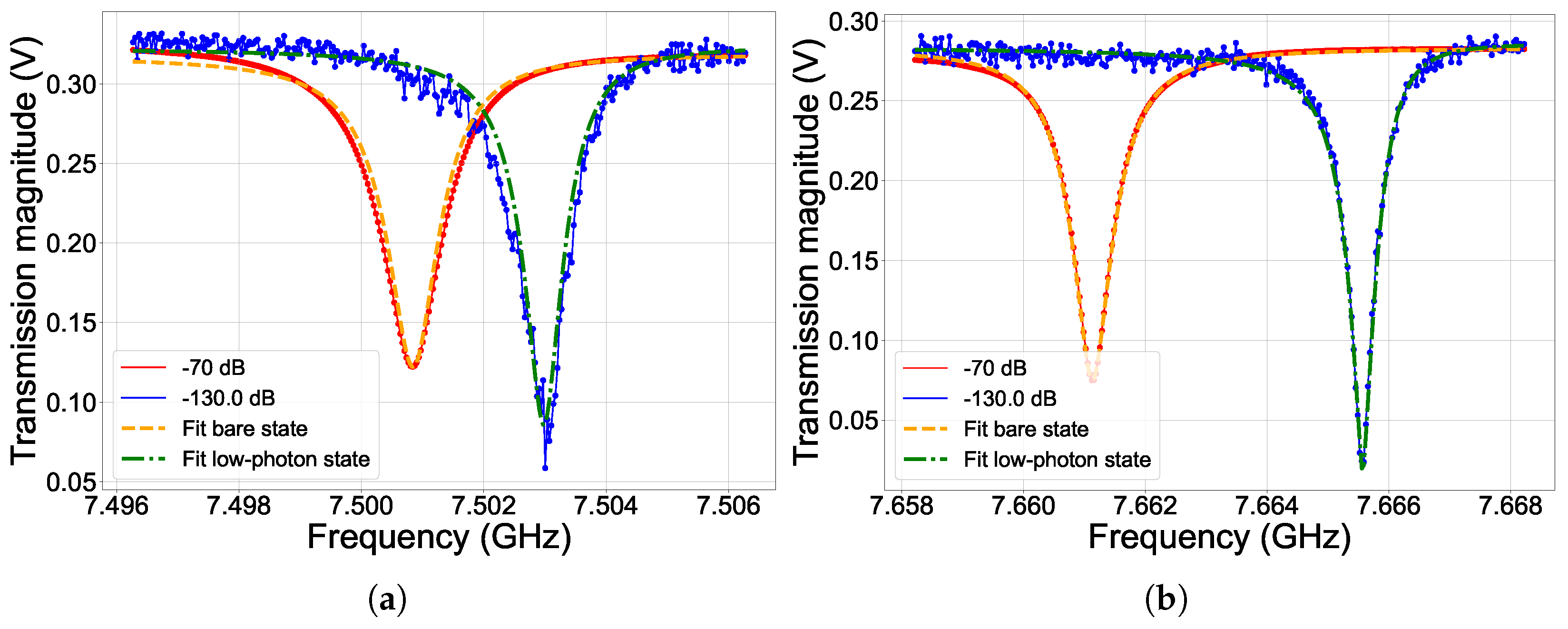
Figure 1. Readout resonator and qubit spectroscopy for superconducting coupled transmon qubits Q a Q b . In (a), readout cavity of Q a and low-photon shift; in (b) for Q b . Scatter-line plots represent the readout response to large ( 70 dBm on the device-under-test, corresponding to around 6–8 × 10 6 photons, in red) input power signal, corresponding to the resonators bare-state, and in the low-power regime ( 130 dBm on the device-under-test, corresponding to tens of photons, in blue). Yellow dashed and green dash-dotted curves correspond to the resonator fit performed with an open-source traceable Python fit routine [71] for the estimation of quality factors in the bare and low-photon states (Table 1), respectively. In (c), Q a pulsed spectroscopy as a function of the qubit-drive attenuation, which adds to roughly 70 dB drive input power on the device-under-test and the qubit-drive frequency. In (d) Q b two-tone pulsed two-tone spectroscopy as a function of the flux and the qubit-drive frequency at fixed qubit drive power on the device-under-test of roughly 80 dB. Please note that the readout resonator frequency has been kept fixed during the measurement, thus causing lower resolution of the qubit frequency peaks far from the flux sweet spot.
Condensedmatter 08 00029 g001aCondensedmatter 08 00029 g001b
Figure 2. In (a,b), Rabi oscillations measured for Q a and Q b , respectively. Data points correspond to the population of the qubit ground state as a function of the duration of the qubit-drive pulse. The red curve represents the Rabi fit, which gives the π -pulse duration reported in the legends.
Condensedmatter 08 00029 g002
Figure 3. Relaxation, Hahn-Echo and Ramsey fitting for qubit Q a and Q b . In (a,b), black (blue) scatter points correspond to the qubit state population as a function of the T 1 ( T 2 E c h o ) sequence duration. Straight orange (red) curves are the fit functions used for the estimation of T 1 ( T 2 E c h o ) time, reported also in the legend. In (c,d), Ramsey oscillations fit for the estimation of T 2 * for Q a and Q b , respectively. Black scatter points correspond to the excited state population as a function of the Ramsey sequence duration, while red lines correspond to the fit. Please note that the χ 2 -minimization of the fitting procedure compensates for the higher ground state population for long sequence durations in the Ramsey oscillations, due to unoptimized π and π / 2 control pulses, with a non-physical ground state probability >1.
Condensedmatter 08 00029 g003
Figure 4. Example of optimization protocol for Randomized Benchmarking on qubit Q b . In (a), Ramsey fringes for qubit Q b from interferometry experiment, fundamental for the optimization of qubit drive frequency signal. In (b), an example of a Derivative-Reductive-Adiabatic-Gate calibration with the All-XY technique on Q b , fundamental for the optimization of qubit drive pulses shape. In (c), All-XY protocol scheme. In (d), experimental demodulated voltage as a function of the DRAG scaling parameter α within the All-XY technique.
Condensedmatter 08 00029 g004
Figure 5. Randomized Benchmarking measurements for single-qubit average gate fidelity F estimation for qubit Q a and Q b . Black scatter data corresponds to a real part of the demodulated readout voltage signal as a function of the number of Clifford gates in the randomized benchmarking sequence, averaged over a number of random seeds n s e e d : in (a), n s e e d = 25 and in (b), n s e e d = 26 , respectively. The error bars represent the standard deviation of the measured data among different repetitions. Straight red curves are the fit functions used for the estimation of the single-qubit randomized benchmarking average gate fidelity F, which is 99.43 % for Q a and 99.34 % for Q b .
Condensedmatter 08 00029 g005
Figure 6. Avoided Level Crossing between Q a and Q b . The colour bar represents the normalized demodulated voltage readout signal ( V V ) / σ V , where V is the average magnitude voltage and σ V is the standard deviation, obtained for a two-tone pulsed spectroscopy measurement of Q b on resonance with Q a . The qubit Q b is put on resonance with Q a by using an external flux coupled to the DC-SQUID in the split-transmon. The red curve represents the Avoided Level Crossing fit reported in Refs. [91,92,94], with which we extract a qubit-qubit coupling energy 2 J = 29 ± 7 MHz.
Condensedmatter 08 00029 g006
Figure 7. In (a), circuit schematics of the coupled superconducting transmon qubits Q a (in blue) and Q b (in black). The two qubits are symmetric split-transmons, coupled by means of a high-frequency resonator bus coupler (in red). Read-out is performed through read-out resonators, capacitively coupled to a common feedline for multiplexing (dark blue). External flux is applied through inductively coupled superconducting flux lines on the chip, while control is done by capacitively coupled dedicated drive lines (not shown). In (b), an example of an optical microscope picture of a similar sample with four qubits coupled through high-frequency bus resonators. Sample geometry and chip dimensions are the same for both devices.
Condensedmatter 08 00029 g007
Figure 8. Schematics of the room-temperature and cryogenic electronics for two-qubit characterization. In blue (red), Q a ( Q b ) setup drive lines. Dashed blue (red) lines are related to flux-bias circuitry. In green, input and output lines schematics. The down-conversion is obtained through a single-sideband three-port mixer, while the up-conversion for both drive and readout input signals is provided by an I-Q mixer.
Condensedmatter 08 00029 g008
Figure 9. Simulations of the total relaxation time due to Purcell and radiative decay in the drive lines T 1 , P and the dielectric losses induced relaxation time T 1 , d for Q b in case of a flip chip configuration. The thickness of the lines represents the error on the estimated values of the order of 30 % . The data are reported as a function of the qubit frequency, and the distance between the QPU and the carrier in the flip-chip qMCM module.
Condensedmatter 08 00029 g009
Table 1. Summary of the Quantum Processing Unit (QPU) with the two coupled split-transmon qubits, Q a and Q b : the 0 1 qubit frequency transition ν 01 at the Sweet-Spot (SS), the qubit anharmonicity α , calculated as twice the frequency separation between ν 01 and the two-photon transition ν 02 / 2 in Figure 1d, the readout resonator frequency in the bare-state ν r , the resonator coupling and intrinsic quality factors Q c and Q i , the readout-qubit detuning Δ , the relaxation time T 1 , the Hahn-echo time T 2 , the Ramsey time T 2 * and the qubit-qubit coupling 2 J . The error on the qubit frequency, estimated as the centre of a Ramsey fringes experiment, is a maximum error related to the acquisition step as a function of the qubit-drive frequency. The error on the resonator frequency is a maximum error related to the readout frequency acquisition step. The error on the quality factors is given a maximum error of 10 % of the fitting routine. The errors on T 2 * and the qubit-qubit coupling strength are the fit errors, while for T 1 , T 2 E c h o they are given as an estimation from statistical measurements.
Q a Q b
ν 01 at SS (GHz) 4.8475 ± 0.0001 5.5167 ± 0.0001
α at SS (MHz)- 321.2 ± 1
ν r (bare state) (GHz) 7.5008 ± 0.0001 7.6611 ± 0.0001
Q c ( 9 ± 1 ) × 10 3 ( 10 ± 1 ) × 10 3
Q i ( 2.7 ± 0.3 ) × 10 4 ( 1.5 ± 0.3 ) × 10 5
Δ (GHz) 2.6534 ± 0.0002 2.1444 ± 0.0002
g (MHz) 112 ± 1 88 ± 1
T 1 ( μ s) 23 ± 2 14 ± 1
T 2 E c h o ( μ s) 44 ± 3 23 ± 2
T 2 * ( μ s) 5.8 ± 0.5 at δ ν = 580 ± 2 kHz 9.1 ± 0.6 at δ ν = 554 ± 1 kHz
2 J (MHz) 29 ± 7
Table 2. Design and materials parameters of the Quantum Processing Unit (QPU) with the two coupled split-transmon qubits, Q a and Q b : the critical temperature T c of the NbTiN readout and coupling resonators, the width of the resonator w and the length gap L g a p and the phase-velocity v p h .
T c 14.6 K
w12 μ m
L g a p 4 μ m
v p h 112 × 10 6 m/s
Disclaimer/Publisher’s Note: The statements, opinions and data contained in all publications are solely those of the individual author(s) and contributor(s) and not of MDPI and/or the editor(s). MDPI and/or the editor(s) disclaim responsibility for any injury to people or property resulting from any ideas, methods, instructions or products referred to in the content.