Article

New Adaptive Control Strategy for a Wind Turbine Permanent Magnet Synchronous Generator (PMSG)

1
School of Electrical Engineering and Automation, Anhui University, Hefei 230610, China
2
College of Engineering and Applied Sciences, Aston University, Birmingham B4 7ET, UK
3
School of Electrical Engineering, Guizhou University, Guiyang 550025, China
4
Goldwind Science Technology Co. Ltd., Beijing 100176, China
*
Authors to whom correspondence should be addressed.
Inventions 2021, 6(1), 3; https://doi.org/10.3390/inventions6010003
Submission received: 24 November 2020 / Revised: 23 December 2020 / Accepted: 24 December 2020 / Published: 28 December 2020
(This article belongs to the Special Issue New Developments of Electrical Machines and Motor Drives)

Abstract

:
Wind energy conversion systems have become a key technology to harvest wind energy worldwide. In permanent magnet synchronous generator-based wind turbine systems, the rotor position is needed for variable speed control and it uses an encoder or a speed sensor. However, these sensors lead to some obstacles, such as additional weight and cost, increased noise, complexity and reliability issues. For these reasons, the development of new sensorless control methods has become critically important for wind turbine generators. This paper aims to develop a new sensorless and adaptive control method for a surface-mounted permanent magnet synchronous generator. The proposed method includes a new model reference adaptive system, which is used to estimate the rotor position and speed as an observer. Adaptive control is implemented in the pulse-width modulated current source converter. In the conventional model reference adaptive system, the proportional-integral controller is used in the adaptation mechanism. Moreover, the proportional-integral controller is generally tuned by the trial and error method, which is tedious and inaccurate. In contrast, the proposed method is based on model predictive control which eliminates the use of speed and position sensors and also improves the performance of model reference adaptive control systems. In this paper, the proposed predictive controller is modelled in MATLAB/SIMULINK and validated experimentally on a 6-kW wind turbine generator. Test results prove the effectiveness of the control strategy in terms of energy efficiency and dynamical adaptation to the wind turbine operational conditions. The experimental results also show that the control method has good dynamic response to parameter variations and external disturbances. Therefore, the developed technique will help increase the uptake of permanent magnet synchronous generators and model predictive control methods in the wind power industry.

1. Introduction

The technology of wind turbines has been imporoving significantly over the last three decades [1,2,3,4]. The wind energy systems installation has increased by 30% in the previous decade. In 2018, the wind power capacity worldwide had reached 597 gigawatts, which is equivalent to 6% of the global electricity demand [5]. However, wind energy is characterised with its intermittency and unpredictability. At the early stage of wind-generation systems, synchronous generators and squirrel-cage induction generators were used for power generation, where any power fluctuations from wind would transmit to the grid. With the improvement of the wind energy conversion system (WECS), doubly fed induction generators (DFIGs) and permanent magnet synchronous generators (PMSGs) have become dominating wind turbine technologies, especially for medium and large wind turbines. Compared to DFIGs which contain the rotor circuit in the machine, PMSGs can eliminate the gearbox and slip rings and thus provide a direct drive option. Furthermore, PMSGs have higher efficiency and power density than any other machines. In order to connect the generator with the power grid, a voltage source converter (VSC) and a pulse-width modulated (PWM) current source converter (CSC) are generally used with advanced control methods [6,7]. It is proved [7] that the latter is easier to achieve the current control and four quadrant operations. Because the PWM-CSC has the capability of controlling the DC voltage and current independently, the dynamic response of the system is excellent. As a result, this research chooses the PWM-CSC as a basic control method for PMSGs.
When the vector control is used in permanent magnet synchronous machines (PMSMs), the speed and rotor position information is mandatory [8]. In order to estimate the related parameters, the measurement sensors are usually chosen for PMSM. However, these sensors are costly and intrusive. Meanwhile, the installation and maintenance of these sensors increase the complexity and cost [9]. Bacause of these, sensorless control methods have been developed for adaptive control purposes. In the sensorless control strategy, the speed and/or rotor position are estimated by an estimator, which is designed by utilising predictive algorithms. Ideally these algorithms need to have excellent efficiency, quick response and low cost. While the design of Kalman filters tends to be sophisticated; switching law design of sliding mode controllers is involved. In the literature, exsiting sensorless methods are inefficient at low speeds or standstill, and some strategies are uneconomical for wind power applications [10,11].
In the developing process of sensorless control techniques, the back electromotive force (EMF) estimation is a common method for PMSM control [12,13]. It is easy to calculate, and provides excellent performance at high speeds. However, a stumbling block is that the back-EMF is dependent on the rotor speed. That is, the back-EMF is very small at low speeds so that it is difficult to achieve the accurate estimation under this condition [14,15,16,17,18]. The first commonly used solution to this problem is to develop a seperate start-up strategy. The second solution is to ultilise another control method with rotor position and speed at the low-speed range. Once the value of back-EMF is large enough, the back-EMF method can resume in operation.
Reference [19] presents a sensorless method for a standalone wind energy conversion system to estimate the power coefficient as per actual wind speeds. This is based on the extended Kalman filter (EKF) estimator. It consists of two steps: a prediction step and a correction step. In the prediction step, both the state vector x k and covariance matrix P p are predicted by expressing the Jacobian F(k). In the correction step, the gain matrix H(k) is determined, and this step corrects the predicted state vector and covariance matrix. Through the use of the EKF estimator, the PMSG currents id, iq and the angular speed ω e can be estimated. The method in [19] builds on a database which can be used to observe the characterisation of the platform. Alternatively, virtual instruments can also provide a sensorless method for wind power adaptive control. Nonetheless, this requires a nonlinear model, implemented by using multilayer perceptron neural networks [20]. This demands for computational resources and basic parameters are still needed to be determined with accuracy.

2. Aims and Objectives

Model reference adaptive system (MRAS) is the most popular strategy for sensorless control nowadays because it can provide a more straightforward implementation and does not have too much computational burden. In the conventional MRAS, the proportional-integral (PI) controller is normally used in the adaptive model and the adaptation mechanism. However, the PI controller is usually tuned by the trial and error method, which is inaccurate and tedious.
Therefore, this work aims to develop a new model reference adaptive control system for PMSG wind turbines. There are three objectives: (i) It develops an improved model predictive control (MPC) system for PMSGs; (ii) it combines the dead-beat control concept with the predictive MRAS observer for estimating the rotor position and speed; (iii) it designs a new robust feature to tune the control parameters and to resist external disturbances by combining a back-EMF with an I-F control method. The control method is tested in simulation and experiments to validate its effectiveness.
Among the control systems, MPC systems have attracted much attention. The leading theory is that it predicts future states based on the system model in every possible control action. The best control action is chosen to minimise the cost function. MPC features with real-time online scrolling optimisation. The algorithm has multi-criteria requirements, and it is relatively simple to implement in the microprocessor. However, it usually requires a larger amount of computation than classical control schemes [21,22]. But tuning parameters is a problem during the control process. When the system parameters change, the output results of the PI controller will degrade dramatically. In order to enhance the capability of resisting disturbances, a sensorless MPC control method for PMSM [23] is developed based on a first-order Euler method. Then, by combining a back-EMF with an I-F control method, a new single-loop MPC is proposed, which merges the current loop and speed loop. This method will simplify the control algorithm and the system structure.

3. Proposed Sensorless Control Algorithm

The WECS is a highly nonlinear and complex coupled system to convert kinetic energy into electricity [24]. Its powertrain includes a wind turbine, an electrical generator, the transmission system, several inverters and converters [25]. Figure 1 shows a diagram of a WECS, and Figure 2 presents an interconnection of a WECS. The option of generator for the WECS can be a DFIG, a PMSG or a caged induction generator. In this research, a PMSG is chosen because of its high power density and direct-drive option.
The operational process of the WECS can be briefly summarised in three steps. The first step is to capture the mechanical aerodynamic energy from wind by the turbine blades. The second step is to convert the mechanical aerodynamic energy into the rotational mechanical one acting on the shaft of the generator. The third step is to convert this mechanical energy into electrical energy by the generator. In order to achieve the maximum power output from a wind turbine generation, a pulse-width modulated (PWM) converter is used to control the rotational speed of the generator as per the available wind energy. Through the generator-side converter and then grid-side inverter, the electrical eneregy is fed into the grid.

3.1. Configrations of PMSGs

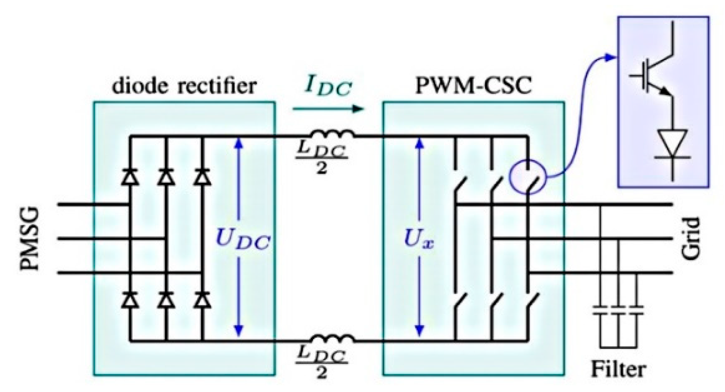
Figure 3 shows three possible configurations for PMSGs. Figure 3a is a back-to-back configuration with two VSCs, which are efficient to manipulate the power flow in the system. As reactive power control is not required in PMSGs, and the diode rectifier can be used to reduce the cost. In order to maintain the DC link voltage and ensure the stability of the system, a DC/DC boost converter can be added between the rectifier and the VSC. This forms the second configration, as shown in Figure 3b. Understandably, there is some extra cost and power loss in the boost converter. Figure 3c shows a PWM-CSC to integrate a PMSG with the power grid. In this configuration, a diode rectifier is used in place of a VSC and the inverter can control the power directly.
Different to the VSC, the electrolytic capacitor is not needed in the PWM-CSC topology and thus reduces the size and cost [28]. Furthermore, the PWM-CSC has the short-circuit protection ability which gives a significant advantage [29].
Figure 4 further illustrates the structure of a PWM-CSC in the wind turbine generator system. When the wind speed is low and the EMF voltage of the machine reduces, the PWM-CSC directly controls the DC current, which significantly improves the efficiency of the system.

3.2. The Proposed Sensorless and Adaptive Control Method

Based on the above analysis, a new sensorless and adapative control method is developed. The schematic diagram of a PMSG wind turbine is shown in Figure 5.
The discrete-time model in the rotating d-q reference frame is given in Equation (1) [30,31]:
u s d [ k ] = ( R s o + Δ R s ) i s d [ k ] + ( L s o + Δ L s ) i s d [ k + 1 ] i s d [ k ] T s ( L s o + Δ L s ) ω r [ k ] i s q [ k ] + ε d [ k ] , u s q [ k ] = ( R s o + Δ R s ) i s q [ k ] + ( L s o + Δ L s ) i s q [ k + 1 ] i s q [ k ] T s + ( L s o + Δ L s ) ω r [ k ] i s d [ k ] + ω r [ k ] ( Ψ p m o + Δ Ψ p m ) + ε q [ k ] ,
where i s d , i s q , u s d and u s q are the d - q axis stator current and voltage of a PMSG, respectively. T s is the sampling time; L s o , R s o and Ψ p m o are the nominal values of the stator inductance, stator resistance and flux linkage, respectively.
In Equation (1), ω r = n p ω m which is the electrical angular speed of the rotor, np is the number of pole pairs and ω m is the mechanical angular speed. ε d [ k ] and ε q [ k ] are the un-modelled d - q axis dynamics, respectively. Δ L s , Δ Ψ p m and Δ R s represent the uncertainty of the stator inductance, PM flux linkage and stator inductance, respectively.
In different types of MPC approaches, the finite control set-model predictive control (FCS-MPC) and the deadbeat predictive (DB) control are two of the well-known methods. In this research, the DB control method is chosen. Although the FCS-MPC has received much attention because it is easy to implement, flexible to define control objectives and excellent in transient performance. Nevertheless, its disadvantages include the steady-state error, variable switching frequency and the need for a reference voltage. By using a space vector PWM (SVPWM), the reference voltage can be translated into the relevant switching actions [32]. But the system parameters are still necessary for the DB predictive control method.
In order to compensate for the unmodeled dynamics and make a piecewise constant variation, this work uses a discrete-time integral action (DTIA) in the DB algorithm. Upon the compensation action, an excellent steady-state response is obtained, and the robustness of DB predictive controller can be improved. The analytical relationship is as follows.
Assum e   R s o , Ψ p m o and L s o are known constants. Because of the change in the frequency, temperature and load, Δ L s , Δ Ψ p m and Δ R s are unknown. Meanwhile, they may change with time. In addition, the un-modelled dynamics ε d [ k ] , ε q [ k ] are subjected to change with operating conditions. Thus, estimating these parameters with accuracy is technically challenging. By replacing i s d q [ k + 1 ] with the reference value i s , r e f d q [ k + 1 ] in Equation (1) and adding the DTIA to Equation (2), the reference voltage u s , r e f d q can be calculated accordingly.
u s . r e f d [ k ] = R s o i s d [ k ] + L s o i s , r e f d [ k + 1 ] i s d ( k ) T s L s o ω r [ k ] i s q [ k ] + k I n = 0 k e d [ n ] , u s . r e f q [ k ] = R s o i s q [ k ] + L s o i s , r e f q [ k + 1 ] i s q ( k ) T s L s o ω r [ k ] i s d [ k ] + ω r [ k ] Ψ p m o + k I n = 0 k e q [ n ] ,
In Equation (2), k I n = 0 k e d [ n ] and k I n = 0 k e q [ n ] represent the DTIA removing the steady-state errors. These increase the robustness of the designed controller. When k I > 0 , the integral control gain and discrete-time current error are e d = i s , r e f d i s d and e q = i s , r e f q i s q , respectively. If k I = 0 , the conventional DB algorithm will be simplified in the system.
In the proposed control strategy, the field-oriented control (FOC) method is applied, which has been widely used in synchronous and induction machines. In this method, the d-axis of the synchronous rotating reference frame aligns with the rotor flux. This alignment allows the magnetic flux and electromagnetic torque to be controlled independently, by controlling the d- and q-axis current components in the synchronous rotating reference frame, respectively. Different to the conventional MRAS, the PI controller in this work is replaced by the DB predictive controller to estimate the speed and rotor position of the PMSG.

4. Simulation Results

In order to study the proposed hybrid control method, a simulation model was first built within MATLAB/Simulink. The key parameters used in the simulation are listed in Table 1 and the detailed control scheme is presented in Figure 6 for illustration.
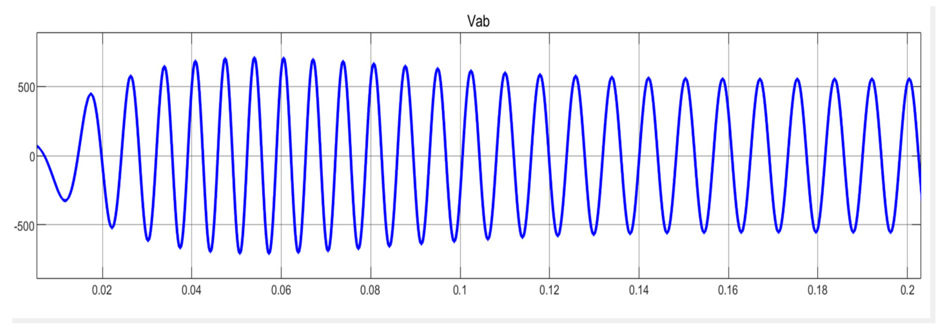
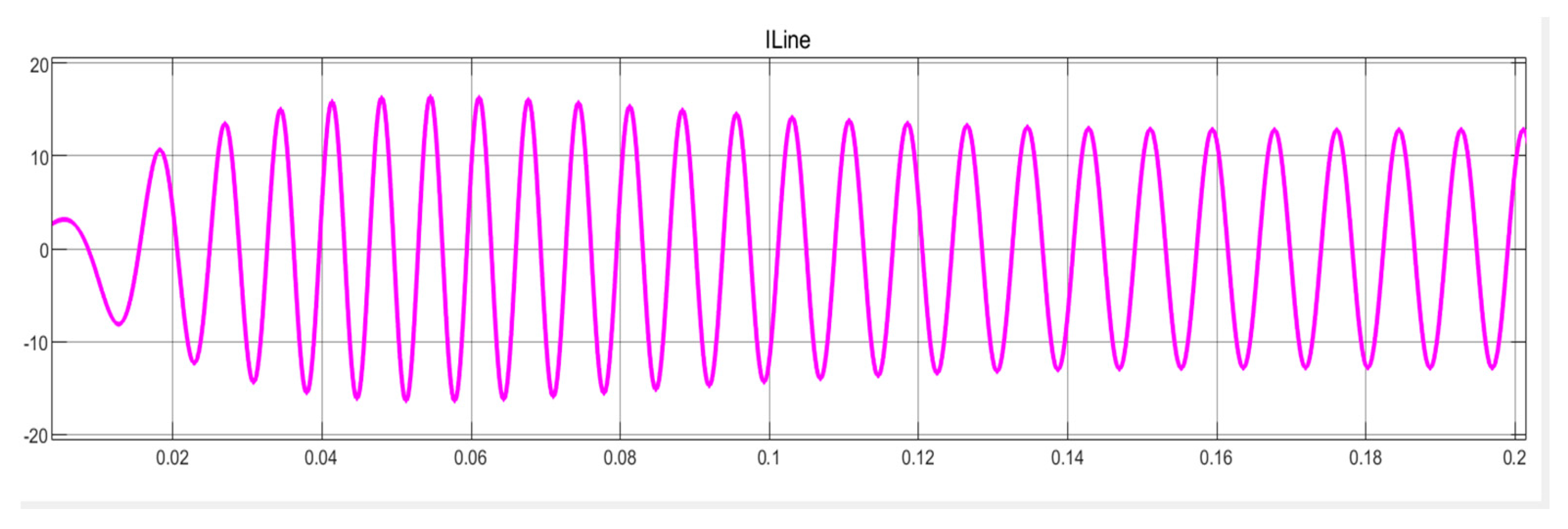
Simulation results are presented in Figure 7, Figure 8, Figure 9, Figure 10, Figure 11 and Figure 12. Figure 7 shows the stator d-q voltages; Figure 8 shows the line to line voltage Vab and Figure 9 shows the line current Ia. It can be seen that these electrical parameters can reach their steady-state and rated volages after a period of 0.15 s, which is three times of the electrical period. Figure 10 presents the electromagnetic torque; Figure 11 presents the speed tracking; and Figure 12 presents the active power output from the wind turbine generator. These are good performance indicators to follow the expected references of the speed, torque and power. Despite slight overshooting in the first cycle, they can quickly arrive the rated values after apporximately three cycles, which are similar to electrical parameters in Figure 7, Figure 8 and Figure 9.
When setting T = 1 s in the simulation model, the active power waveform is obtained, as shown in Figure 12. From 0.02 s, the power starts to increase till 6123 W. Then, increasing T to 2, the power reaches 6120 W. When setting T = 3, the power reaches 6241 W. A comparison of results is given in Table 2 for the generator operating without an active control method, with MRAS and the proposed methods. It is shown that the PMSG using the proposed method can generate 3% more power than the conventional MRAS method, and 6% more power than that without employing an active method. A clear improvement of energy efficency is demonstrated in this study.

5. Experimental Results

In order to verify the effectiveness of the proposed method, an experimental test rig is set up. It consists of two EMJ-04APB22 servo motors, two High Voltage Motor Control and PFC Developer’s Kits (Texas Instruments). Among the two identical machines, they work back-to-back as a motor-generator (M-G) set, one acting as a motor to drive another working as a generator. The inverter switching frequency is 10 kHz. In the reference model, a low pass filter (LPF) is used to replace the integrator. The cut-off frequency of the LPF is set at 2 Hz.
The PMSG is tested under different loads and with different parameter variations to validate the effiectiveness of the proposed MPC-MRAS method. As a comparison, the existing MRAS method is used as the benchmark. Some test results are shown in Figure 13, Figure 14 and Figure 15.
Figure 13 shows the PMSG’s speed-tracking performance under the the mutual inductance change at no load. The estimation error is given by the difference between the measured parameter and estimated parameter. The accuracy of the control algorithms can be observed by comparing the similarities between the estimated parameters and the measured parameters lines in the figure. It is clear that the proposed MPC-MRAS control method can resist the disturbance from the Lm change whilst the conventional MRAS method leads to significant fluctuations in the rotor speed. Moreover, the system stability has become an issue. Figure 14 presents the speed-tracking performance under the reference speed change from 30 to 60 rpm at full load. Upon a reference speed change, the PMSG with the proposed control method has reached a steady-state quickly and speed changes are low. On the contrary, the conventional MRAS presents continuous oscillations which are not dampened out after 5 s. Figure 15 demonstrates the speed-tuning signal under the reference speed change from 40 to 100 rpm at full load. After 2 s, the speed-tuning signal for the proposed control method remains at 0.012, but the speed tuning signal of conventional MRAS control method suddenly changed to 0.122 at 2 s. After then, it becomes very unstable. Clearly, the conventional MRAS gives rise to the fluctuations, which are as high as six times of that with the proposed method.
From experimental tests, Figure 13, Figure 14 and Figure 15 demonstrate excellent robustness of the proposed MPC-MRAS control method as compared to the conventional MRAS control system.

6. Conclusions

This paper has presented a new sensorless and adaptive control method for variable speed control of a surface-mounted PMSG for wind turbine application. The use of a PWM-CSC helps operate the wind turbine under critical conditions. The proposed control method combines the dead-beat control concept with the predictive MRAS observer for estimating the rotor position and speed. Test results from simulation and experiments have confirmed that the proposed control system is effective and reliable. Compared to the existing methods, the proposed method provides better dynamic performance for PMSGs in wind turbine applications. Therefore, this control scheme has great potential to improve the dynamics and efficiency of wind turbine generators, thus promoting the uptake of PMSGs in the wind power industry.
However, in this work, the proposed control method has been tested on low-power PMSMs, which are off-the-shelf general-purpose machines used as PMSGs. In the further work, the developed technology will be implemented and field tested in medium and large wind turbine generators provided by the industrial partner Goldwind. Moreover, new artificial intelligence (AI)-based maximum power point tracking (MPPT) algorithms will also be developed and included in the control scheme so as to maximise the yield of wind turbines.

Author Contributions

In this work, the conceptualisation is developed by W.C. and N.X.; methodology, N.X. and X.C.; software, Y.W.; validation, N.X. and D.W.; writing—original draft preparation, N.X.; writing—W.C. and X.C.; supervision, W.C. and D.W. All authors have read and agreed to the published version of the manuscript.

Funding

This research was funded by Goldwind grant number 2016144.

Data Availability Statement

Data available on request due to restrictions. The data presented in this study are available on request from the corresponding authors. The data are not publicly available due to commercial reasons.

Conflicts of Interest

The authors declare no conflict of interest.

References

  1. Blaabjerg, F.; Chen, Z. Power electronics for modern wind turbines. Synth. Lect. Power Electron. 2006, 1, 1–68. [Google Scholar] [CrossRef]
  2. Arshad, M.; O’Kelly, B.C. Offshore wind-turbine structures: A review. Proc. Inst. Civ. Eng. Energy 2013, 166, 139–152. [Google Scholar] [CrossRef]
  3. Failla, G.; Arena, F. New perspectives in offshore wind energy. Philos. Trans. R. Soc. A Math. Phys. Eng. Sci. 2015, 373, 20140228. [Google Scholar] [CrossRef] [PubMed] [Green Version]
  4. Arrambide, I.; Zubia, I.; Madariaga, A. Critical review of offshore wind turbine energy production and site potential assessment. Electr. Power Syst. Res. 2019, 167, 39–47. [Google Scholar] [CrossRef]
  5. WWEA. Wind Power Capacity Worldwide Reaches 597 GW, 50, 1 GW Added in 2018. Available online: https://wwindea.org/blog/2019/02/25/wind-power-capacity-worldwide-reaches-600-gw-539-gw-added-in-2018/ (accessed on 25 February 2019).
  6. Dai, J. Current Source Converters for Megawatt Wind Energy Conversion Systems. Ph.D. Dissertation, Ryerson University, Toronto, ON, Canada, 2010. [Google Scholar]
  7. Lang, Y.; Wu, B.; Zargari, N. A high-power current source converter based wind energy system. IEEE Trans. Ind. Appl. 2008, 55, 2786–2797. [Google Scholar]
  8. Li, Y.; Zhu, H. Sensorless control of permanent magnet synchronous motor—A survey. In Proceedings of the 2008 IEEE Vehicle Power and Propulsion Conference (VPPC), Harbin, China, 3–5 September 2008. [Google Scholar]
  9. Singh, S.; Anvari-Moghaddam, A. Sensor-based and sensorless vector control of PM synchronous motor drives: A comparative study. In Proceedings of the 2018 IEEE 4th Southern Power Electronics Conference (SPEC), Singapore, 10–13 December 2018; pp. 1–6. [Google Scholar]
  10. Sun, Y.; Preindl, M.; Sirouspour, S.; Emadi, A. Unified wide-speed sensorless scheme using nonlinear optimization for IPMSM drives. IEEE Trans. Power Electron. 2017, 32, 6308–6322. [Google Scholar] [CrossRef]
  11. Zhao, H.; Wang, Z.; Xu, Y. A new speed sensorless controller based on double observers for permanent-magnet synchronous motor. In Proceedings of the 2016 8th International Conference on Intelligent Human-Machine Systems and Cybernetics (IHMSC), Hangzhou, China, 27–28 August 2016; pp. 401–404. [Google Scholar]
  12. Giri, F. (Ed.) AC Electric Motors Control: Advanced Design Techniques and Applications; John Wiley & Sons, Ltd.: Hoboken, NJ, USA, 2013. [Google Scholar]
  13. Nahid-Mobarakeh, B.; Meibody-Tabar, F.; Sargos, F.-M. Back-EMF estimation based sensorless control of PMSM: Robustness with respect to measurement errors and inverter irregularities. In Proceedings of the Conference Record of the 2004 IEEE Industry Applications Conference, 2004. 39th IAS Annual Meeting, Seattle, WA, USA, 3–7 October 2004; pp. 1858–1865. [Google Scholar]
  14. Hassan, M.A.; Mahgoub, O.; El Shafei, A. ANFIS based MRAS speed estimator for sensorless control of PMSM. In Proceedings of the 2013 Brazilian Power Electronics Conference, Gramado, Brazil, 27–31 October 2013; pp. 828–835. [Google Scholar]
  15. Mishra, A.; Mahajan, V.; Agarwal, P.; Srivastava, S.P. MRAS based estimation of speed in sensorless PMSM drive. In Proceedings of the 2012 IEEE Fifth Power India Conference, Murthal, India, 19–22 December 2012; pp. 1–5. [Google Scholar]
  16. Xiao, D.; Guan, D.Q.; Rahman, M.F.; Fletcher, J. Sliding mode observer combined with fundamental PWM excitation for sensorless control of IPMSM drive. In Proceedings of the IECON 2014—40th Annual Conference of the IEEE Industrial Electronics Society, Dallas, TX, USA, 29 October–1 November 2014; pp. 895–901. [Google Scholar]
  17. An, L.; Franck, D.; Hameyer, K. Sensorless field oriented control using back-EMF and flux observer for a surface mounted permanent magnet synchronous motor. Int. J. Appl. Electromagn. Mech. 2014, 45, 845–850. [Google Scholar] [CrossRef]
  18. Nagarajan, V.S.; Balaji, M.; Kamaraj, V. Back-emf-based sensorless field-oriented control of PMSM using neural-network-based controller with a start-up strategy. Adv. Intell. Syst. Comput. 2015, 325, 449–457. [Google Scholar]
  19. Mesbahi, A.; Raihani, A.; Bouattane, O.; Saad, A.; Khafallah, M. Extended Kalman Filter for characterizing a wind energy conversion system based on variable speed permanent magnet synchronous generator. In Proceedings of the 2014 International Renewable and Sustainable Energy Conference (IRSEC), Ouarzazate, Morocco, 17–19 October 2014. [Google Scholar]
  20. Fortuna, L.; Giannone, P.; Graziani, S.; Xibilia, M.G. Virtual instruments based on stacked neural networks to improve product quality monitoring in a refinery. IEEE Trans. Instrum. Meas. 2007, 56, 95–101. [Google Scholar] [CrossRef]
  21. Rodriguez, J.; Cortes, P. Predictive Control of Power Converters and Electrical Drives; Wiley—IEEE Press: New York, NY, USA, 2012; Volume 40. [Google Scholar]
  22. Rodriguez, J.R.; Kazmierkowski, M.P.; Espinoza, J.R.; Zanchetta, P.; Abu-Rub, H.; Young, H.A.; Rojas, C.A. State of the art of finite control set model predictive control in power electronics. IEEE Trans. Ind. Inform. 2013, 9, 1003–1016. [Google Scholar] [CrossRef]
  23. Gao, J.; Liu, J.; Gong, C. A high-efficiency PMSM sensorless control approach based on MPC controller. In Proceedings of the IECON 2018—44th Annual Conference of the IEEE Industrial Electronics Society, Washington, DC, USA, 21–23 October 2018; pp. 2171–2176. [Google Scholar] [CrossRef]
  24. Funabashi, T. Chapter 1: Introduction. In Integration of Distributed Energy Resources in Power Systems; Academic Press: Cambridge, MA, USA, 2016; pp. 1–14. [Google Scholar]
  25. Yaramasu, V.; Wu, B. Predictive control of a three-level boost converter and an NPC inverter for high-power PMSG-based medium voltage wind energy conversion systems. IEEE Trans. Power Electron. 2014, 29, 5308–5322. [Google Scholar] [CrossRef]
  26. WindML. How Do the Wind Turbines Work? Available online: https://www.windml.org/how-do-the-wind-turbines-work/ (accessed on 22 April 2020).
  27. Giraldo, E.; Garces, A. An adaptive control strategy for a wind energy conversion system based on PWM-CSC and PMSG. IEEE Trans. Power Syst. 2014, 29, 1446–1453. [Google Scholar] [CrossRef]
  28. Yang, S.; Xiang, D.; Bryant, A.; Mawby, P.; Ran, L.; Tavner, P. Condition monitoring for device reliability in power electronic converters: A review. IEEE Trans. Power Electron. 2010, 25, 2734–2752. [Google Scholar] [CrossRef]
  29. Bai, Z.; Zhang, Z.; Ruan, X. A natural soft-commutation PWM scheme for current source converter and its logic implementation. IEEE Trans. Ind. Electron. 2011, 58, 2772–2779. [Google Scholar] [CrossRef]
  30. Abdelrahem, M.; Hackl, C.M.; Kennel, R. Simplified model predictive current control without mechanical sensors for variable-speed wind energy conversion systems. Electr. Eng. 2017, 99, 367–377. [Google Scholar] [CrossRef]
  31. Abdelrahem, M.; Hackl, C.; Kennel, R. Sensorless control of doubly-fed induction generators in variable-speed wind turbine systems. In Proceedings of the 2015 International Conference on Clean Electrical Power (ICCEP), Taormina, Italy, 16–18 June 2015; pp. 406–413. [Google Scholar]
  32. Morel, F.; Lin-Shi, X.; Retif, J.-M.; Allard, B.; Buttay, C. A comparative study of predictive current control schemes for a permanent-magnet synchronous machine drive. IEEE Trans. Ind. Electron. 2009, 56, 2715–2728. [Google Scholar] [CrossRef] [Green Version]
  33. Lopez-Ortiz, E.N.; Campos-Gaona, D.; Moreno-Goytia, E. Modelling of a wind turbine with permanent magnet synchronous generator. In Proceedings of the 2012 North American Power Symposium (NAPS), Champaign, IL, USA, 9–11 September 2012; pp. 1–6. [Google Scholar]
Figure 1. Components in a wind energy conversion systems [26].
Inventions 06 00003 g001
Figure 2. Illustration of interconnection of the wind energy conversion system (WECS).
Inventions 06 00003 g002
Figure 3. Three possible configurations for permanent magnet synchronous generators (PMSG) integration: (a) back-to-back converters with voltage source converters (VSCs). (b) Diode-bridge rectifier and boost converter. (c) pulse-width modulated-current source converter (PWM-CSC) [27].
Inventions 06 00003 g003
Figure 4. Schematic diagram of the conventional PWM-CSC.
Inventions 06 00003 g004
Figure 5. The schematic control diagram of a variable speed wind turbine PMSG.
Inventions 06 00003 g005
Figure 6. The proposed adaptive control method for the variable speed PMSG based on PWM-CSC.
Inventions 06 00003 g006
Figure 7. Stator d-q voltages.
Inventions 06 00003 g007
Figure 8. Line to line voltage Vab.
Inventions 06 00003 g008
Figure 9. Line current Ia.
Inventions 06 00003 g009
Figure 10. Electromagnetic torque.
Inventions 06 00003 g010
Figure 11. Speed tracking.
Inventions 06 00003 g011
Figure 12. Active power output of the wind generator.
Inventions 06 00003 g012
Figure 13. Speed-tracking performance under the Lm change at no load. (a) model reference adaptive system (MRAS) control method. (b) Proposed model predictive control (MPC)-MRAS control method.
Inventions 06 00003 g013
Figure 14. Speed-tracking performance under the reference speed change from 30 to 60 rpm at full load. (a) MRAS control method. (b) Proposed MPC-MRAS control method.
Inventions 06 00003 g014
Figure 15. Speed-tuning signal under the reference speed change from 40 to 100 rpm at full load. (a) MRAS control method. (b) Proposed MPC-MRAS control method.
Inventions 06 00003 g015
Table 1. Parameters of the PMSG wind turbine system [33].
ParameterValue
Rated power P (W)6000
Base power of the generator S (VA)9444.44
Base wind turbine speed (m/s)12
Rated speed ω (rad/s)153
Stator resistance R (Ω)0.425
No. of the pole pair5
Rotor flux linkage (Wb)0.433
Inertia J (kg m2)0.01197
Armature inductance L (H)0.000395
Stator inductance L (H)0.000835
Viscous damping F (N·m·s)0.001189
The density of air ρ (kg m3)1.225
Area swept by blades A (m2)1.06
Table 2. Comparison of the output power using different control methods.
Types of Control MethodsT = 1T = 2T = 3
Without active control method614360165974
MRAS control method613260566078
Proposed MPC-MRAS method612361206241
Publisher’s Note: MDPI stays neutral with regard to jurisdictional claims in published maps and institutional affiliations.