Article

Calibration Dependencies and Accuracy Assessment of a Silicone Rubber 3D Printer

1
Austrian Center for Medical Innovation and Technology (ACMIT Gmbh), Viktor-Kaplan-Strasse 2/A, 2700 Wiener Neustadt, Austria
2
Institute of Lightweight Design and Structural Biomechanics, Technical University of Vienna, Object 8, Gumpendorfer Strasse 7, 1060 Vienna, Austria
3
Department of Anatomy and Biomechanics, Karl Landsteiner University of Health Sciences, Dr.-Karl-Dorrek-Strasse 30, 3500 Krems an der Donau, Austria
*
Author to whom correspondence should be addressed.
Inventions 2022, 7(2), 35; https://doi.org/10.3390/inventions7020035
Submission received: 19 March 2022 / Revised: 30 March 2022 / Accepted: 31 March 2022 / Published: 4 April 2022
(This article belongs to the Special Issue Innovations in 3D Printing 2.0)

Abstract

:
Silicone rubbers are relatively new in additive manufacturing, with only a few commercial printing services and reports on custom-built printers available. Publications and standards on calibration and accuracy assessment are especially lacking. In this study, the printhead calibration process of a custom-built silicone printer is explained, and a set of test objects is proposed and evaluated. The printer in use is based on an open-source filament printer, capable of multi-material printing with silicone rubbers and thermoplastic polymers. Three different high-viscosity single-component liquid silicone rubbers and one polylactic acid thermoplastic filament were used as printing materials. First, the calibration process of the silicone printhead was conducted, and the dependency of the dosing accuracy on silicone viscosity, nozzle diameter and extrusion speed was evaluated. Second, various test specimens were proposed and printed to characterize the accuracy and geometric limitations of this printer. These test parts contained features such as thin walls, slender towers, small holes and slots, unsupported overhangs and bridges. It was concluded that silicone viscosity strongly affects geometric inaccuracies. Design recommendations were deducted from the results, advising for wall thicknesses above 1 mm, slenderness ratios below 2, bridging lengths below 2 mm and unsupported overhang angles below 30°.

1. Introduction

1.1. Silicone Rubber 3D Printing

Additive manufacturing (AM), or 3D printing, is a group of technologies that is transforming industry and research by enabling the manufacturing of complex objects from various materials without expensive tooling [1,2,3,4,5,6]. One of the quickly advancing domains is 3D printing with various fluid materials that solidify upon some physical or chemical stimulus after deposition, resulting in a soft object. This includes a large variety of materials, such as hydrogels, waxes or rubbers, and the deposition may happen via continuous extrusion or droplet jetting [1]. Such materials have been used in regenerative medicine and tissue engineering [7,8,9]. Recent advances in material development also made extrusion-based silicone rubber printing available [7,10,11] to a greater variety of medical and technical applications. While silicone rubber 3D printing is already available through various commercial services and off-the-shelf printers [12,13,14,15], detailed reports [16] on custom-built systems—including their setup and calibration—are scarce, even though custom-built systems may offer greater freedom in customization and lower costs in research.

1.2. Accuracy and Geometric Limitation Assessment

Every AM technology—including silicone printing—bears various strengths and weaknesses, which must be considered in any given use case. Geometric accuracy and object stability are important factors, since those influence design freedom. To help the assessment of geometric capabilities of various AM systems, several studies [17,18,19,20,21] and standards [22,23,24] have been published. Geometric limitation assessment is a prerequisite for any further testing, such as mechanical characterization [25,26,27], since it is preferrable to confirm the manufacturability and accuracy of test specimens before proceeding to further assessments that require those specimens. In theory, printing such test objects should help the user decide whether the system in question can manufacture a desired product.
However, many recommended test objects are general and ignore significant differences among various technologies [21,24]. Moreover, it is often recommended to test the feasibility of different features on a single, complicated test object [21]. While this approach simplifies and speeds up the assessment process, it makes dimension measurements from certain angles difficult and also runs the risk of “failure transfer”, where the failure of one feature influences the success of another feature, potentially distorting test results. Failure transfer is especially dangerous in extrusion-based technologies, where the material from a failed feature can accumulate on the nozzle and get transferred—and deposited—elsewhere, influencing the success of other features.
Even though such shortcomings are pronounced in both filament-based [28] and fluid extrusion-based printing, they are more neglected in the case of fluid printing including silicone printing. In addition, apart from failure transfer, the viscosity and crosslinking kinematics of the used silicone material may also influence geometric limitations in the case of extrusion-based silicone printing. The evaluation of unstable features, such as high slenderness ratio columns, thin shells, small holes and slots, unsupported overhangs and bridges, is important in many use cases, but test methods and specimens designed for this technology—that also reduce the chance of failure transfer—seem to be lacking in current standards and best practice.

1.3. Research Objectives

There were two aims to this study. The first was to investigate the influence of extrusion speed, nozzle diameter and printing material viscosity on the dosing accuracy of a custom-built silicone 3D printer through a detailed calibration protocol. This may be helpful for researchers aiming to build their own custom fluid printer based mostly on open-source filament printer hardware, firmware and software. The second aim was to establish an accuracy testing approach that limits the chance of failure transfer and points out the geometric limitations with regards to various geometric features. The identified geometric limits were also compared to those of thermoplastic filament printing, which was used as a benchmark due to the fact of its popularity and accessibility.

2. Materials and Methods

The printer system used in this study was introduced elaborately in [29]; therefore, the description given here for the printer and the materials is relatively brief. However, the calibration process of the fluid extruder and the objects for geometric limitation assessment are described in detail.

2.1. Printer and Materials

The custom 3D printer used in this study (Figure 1) consisted of a Railcore II 300 ZL 3D printer [30] (Railcore Labs LLC, Goshen, IN, USA) with an E3D V6 filament hotend [31,32] (E3D-Online Ltd., Oxford, UK), extended with an additional Viscotec Vipro-HEAD 3/3 dual fluid extruder [33] (Viscotec GmbH, Töging am Inn, Germany). In the latter, the liquid silicone rubber material is fed from two 55 mL pressurized cartridges (both at 6 bars) to each extruder. Only one of the two silicone extruders was used for printing in this study, but both may be used within the same print run. The system relies on a Duet 2 control board [34], which allowed for the extension with the Viscotec extruders.
Three high-viscosity single-component liquid silicone rubbers—AMSil 20101, 20102 and 20103, Elkem Silicones (Lyon, France) [35]—were used. These materials are designed for 3D printing via extrusion at room temperature, therefore no heating or other means of energy input is required during printing. After printing an object, minimum 24 h of curing time is allowed on room temperature before any evaluation. The filament printhead used a poly-lactic acid (PLA) thermoplastic filament (Material 4 Print GmbH, Löhne, Germany), which was chosen as a benchmark due to the popularity and accessibility of PLA filaments. The properties of all used printing materials are visible in Table 1 based on the corresponding technical datasheets. Further description concerning the initial test prints with the printer system is available in [29]. The materials are referred to as 20101, 20102, 20103 and PLA in the rest of this study.

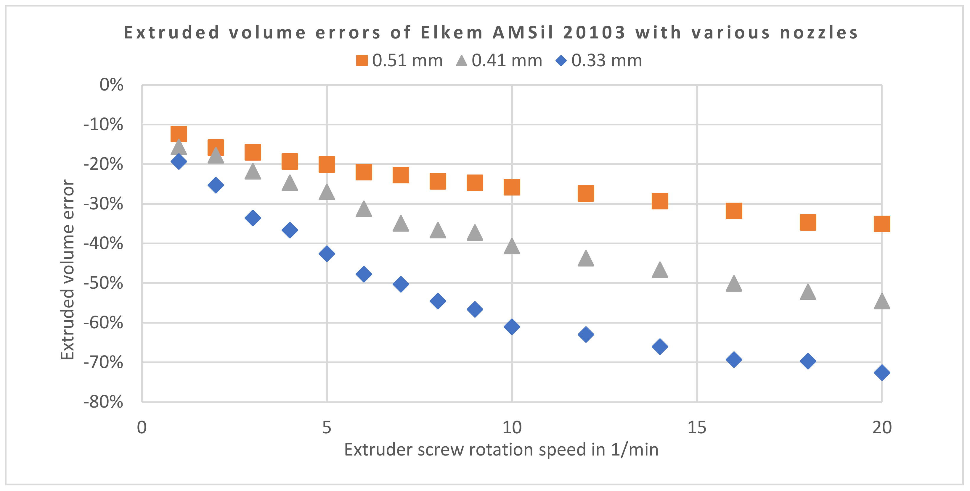
2.2. Fluid Extruder Calibration

The calibration of the Viscotec fluid extruder for each material is important before any printing test, since the material viscosity and the nozzle diameter both influence the dosing accuracy. The following description focuses on the fluid extruder and 3D printer used in this study, but the calibration process is likely transferable to other extruders and printer electronics. All data handling in this work was done in Microsoft Excel, and PrusaSlicer v2.3.0 (Prusa Research a.s., Prague, Czech Republic) was used for print file generation.
Typically, in filament 3D printers, a calibration coefficient, expressed in step/mm (of filament), is used to define the relationship between stepper motor revolution and filament pushed forward. However, no filament is present in a fluid extruder, which makes it more practical to “think” in terms of extruded fluid volume instead of extruded length. This necessitates the calculation of an “equivalent filament diameter” (EFD) to use a fluid extruder with a filament 3D printer firmware and slicer software (PrusaSlicer) that “thinks” in filament length instead of volume. It was practical to use a 1.13 mm EFD that returns approximately 1 mm3 volume (V1) for each 1 mm of “equivalent filament” length (h1), as expressed in Equation (1) below, based on the simple formula of the volume of a cylinder.
E F D = 4 V 1 h 1 π = 4 π 1.13   mm
where   V 1 = 1   mm 3 ;   h 1 = 1   mm .
This value was used in the slicer software as a filament diameter setting. After this step, the value of the calibration coefficient (normally given in step/mm) in the printer configuration file may also be interpreted in step/mm3.
Each of the two extruders of the printhead featured an encoded DC motor with built-in position controller, which—from the perspective of the printer control board—made them appear as high angular resolution stepper motors with a 12,500 step/revolution constant. Furthermore, each extruder revolution pushed forward a theoretical volume of 30 mm3 according to the manufacturer. However, the flow rate stemming from these theoretical values is heavily influenced by fluid viscosity and nozzle diameter. Knowing the theoretical volume/revolution (Vrev = 30 mm3) and the motor step/revolution (cmotor = 12,500 step/rev) values, the theoretical calibration coefficient ccalib,theor can be calculated according to Equation (2).
c calib , theor = c motor V rev = 12500 30 417   step mm ³
In our case, this returned a 417 step/mm3 (or step/mm of 1.13 mm imaginary EFD filament) theoretical calibration coefficient. However, this had to be adjusted due to the significant losses caused by a high fluid viscosity and small nozzle diameter. Characterizing this underextrusion for a given material, nozzle and speed was conducted by first commanding the printer to extrude a desired amount of material volume (Vcmd, usually 500 mm³ in our measurements). A weighing of the extruded material followed (mextr) using a KERN PES 4200-2M laboratory scale (Kern&Sohn GmbH, Balingen, Germany), calculating the extruded volume (Vextr) through known density (ρmat, values in Table 1) and, finally, calculating the volume error (ε) as shown in Equation (3). This was repeated for different extruder screw rotation speeds (ω) up to 20 revolutions per minute, which covered the practical range of usage in this study. The graph resulting from the data points shows the connection between extrusion volume error and extrusion speed, assuming a constant material viscosity and density, feed pressure and nozzle diameter.
ε ω = V extr ω V cmd V cmd · 100 %
where   V cmd = const ;   V extr ω = m extr ω ρ mat .
These extrusion volume errors along the various nozzle diameters and extrusion speeds were compared across the three silicone rubber materials and three different nozzle diameters. The most practically relevant nozzle diameter (0.41 mm) was chosen for further investigations, since this is the closest to the standard 0.40 mm nozzle diameter frequently used in thermoplastic filament printing, making it an ideal choice for comparisons. The extrusion volume error with the chosen 0.41 mm nozzle was speed dependent over the available extrusion speed range. This is problematic, since in each printhead move, there is an initial acceleration and final deceleration phase, swiping over all possible extrusion speeds between zero and the desired printing speed. If one could only compensate extrusion errors with a single constant multiplier in the firmware—by changing the calibration coefficient—one would need to accept either an overextrusion at the beginning and end of each printed line, or an underextrusion in the middle, because the extrusion error is speed dependent.
Fortunately, the firmware of the Duet 2 control board offers a feature that allows for a compensation with a second-order polynomial. The extrusion correction factor ccorr is calculated according to Equation (4), where A, B and C are user-defined parameters, and v is the volume flow command understood in mm3/s. Equation (4) also defines the connection between this volume flow command and the extruder screw rotation speed. The nonlinear compensation feature is accessible with G-code command M592 in the Duet firmware, for which the proper syntax and a further description are found in [36]. It must be noted that the naming of the parameters (i.e., A, B and C) is slightly different here than in [36] to make reading easier.
c corr = A v 2 ω + B v ω + C = 1 1 + ε ω
where   v ω = ω   ·   V r e v   60   = ω 2   mm 3 s .
The extrusion correction factors were calculated from the relative volume error data obtained in the previous step, using three materials, focusing on a 0.41 mm nozzle diameter. While the A and B parameters of the fitted second-order polynomials provided the parameters to use in G-code command M592, the parameter C helped us determine the true calibration coefficient (ccalib,true) according to Equation (5).
c calib , true = c calib , theor · C
For this study, the parameters in Table 2 ensured sufficient printing accuracy for the test specimens described in the following subsection. With this, the extruder calibration for each silicone material is complete. The process described in this subsection may serve as a reference for other self-built systems featuring similar deposition principles but different hardware and firmware.

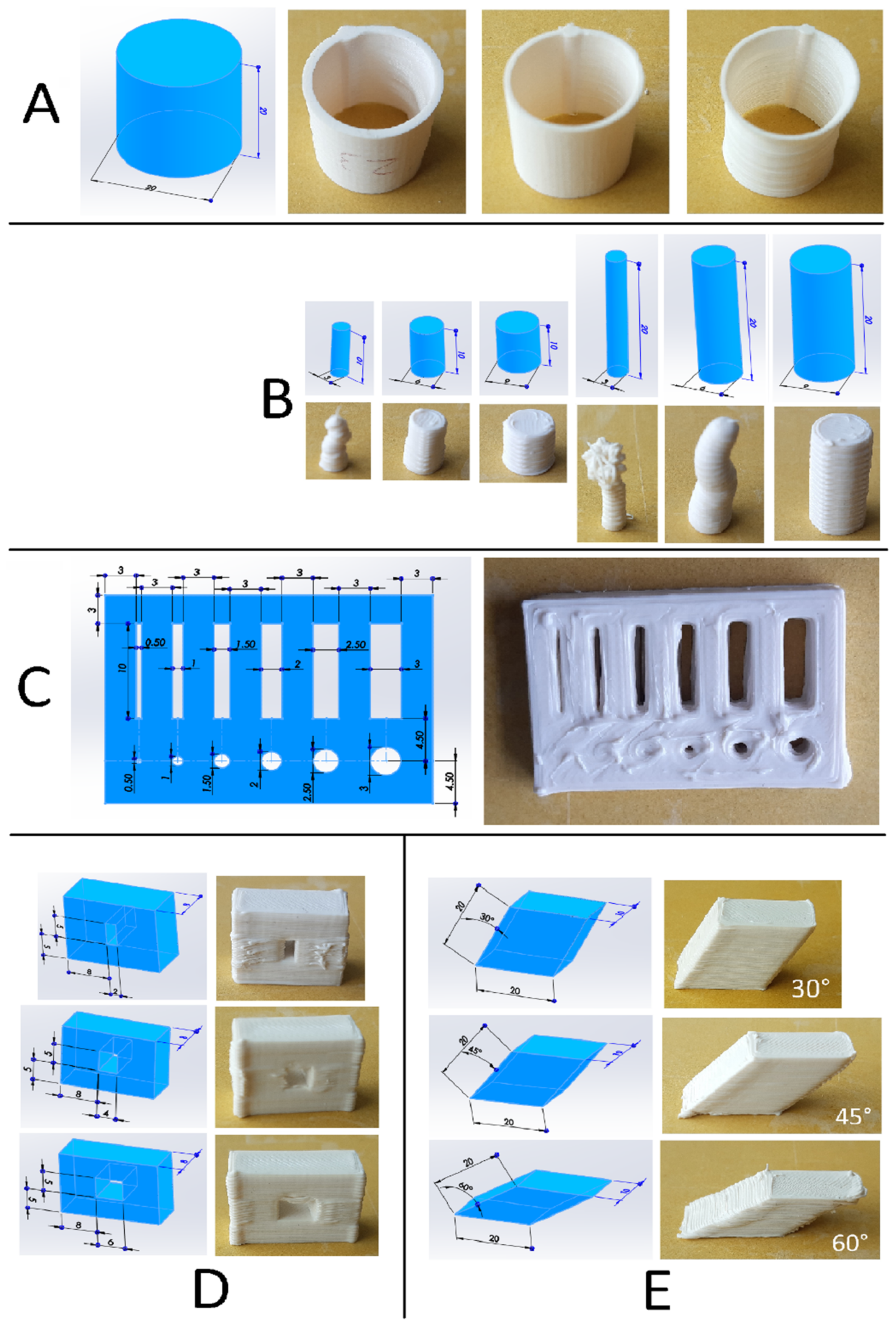
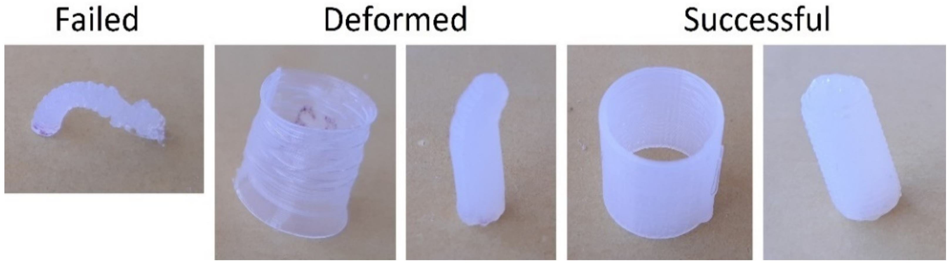
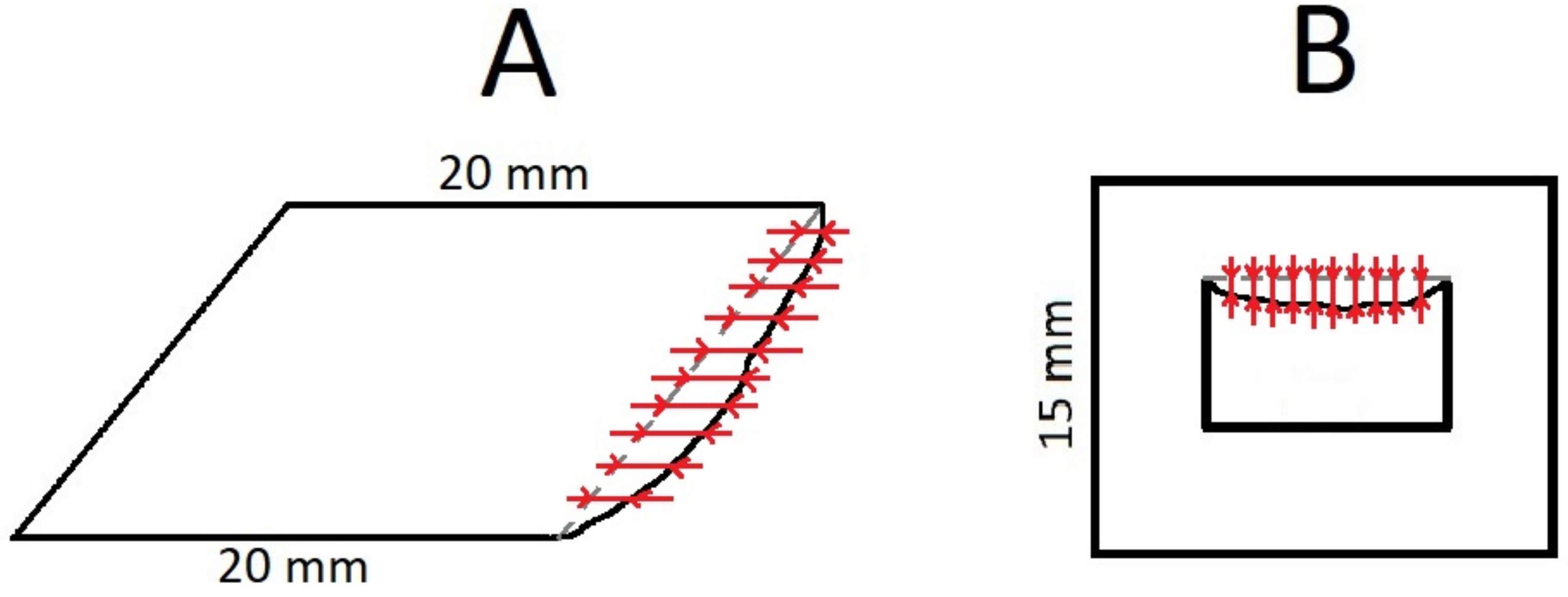
2.3. Assessment of Geometric Limitations

The next step after calibration was evaluating the geometric limitations of the printer with the given materials. This was conducted by printing different geometries that demonstrated various features both in the layer plane and the building direction. The chosen geometries are described further in this subsection. To minimize the chance of “failure transfer”, different geometries were printed in different print runs, while all replicates of the same geometry were printed sequentially within the same run.
All silicone rubber and PLA objects were printed at a constant 30 mm/s printing speed, understood as the target travel speed of the printhead on its trajectory. All objects, except shells, featured a double-line contour, a 0.3 mm layer thickness and a 100% rectilinear infill structure with the infill printed before the contour in each layer. The silicone rubber objects were printed with a 0.41 mm nozzle with direct contact to the unheated building platform. The PLA objects were printed at a 200 °C nozzle and a 60 °C building platform temperature with a 0.4 mm nozzle and with two raft-layers to increase stability during printing. These rafts were removed after printing. All printing was conducted in an ambient temperature of 20–25 °C and 60–70% relative humidity; both were logged with an EL-USB-2 logging device (Lascar Electronics Ltd., Salisbury, UK) and placed next to the printer. After printing, the silicone objects were left in the same ambient conditions to crosslink for 24 h; then, they were carefully removed from the building platform using a razor blade.
The silicone nozzle diameter choice of 0.41 mm (0.4 mm for filaments) also determines the minimal feature size with the given nozzle by constraining the thickness of a single extruded line. In our case, this extruded line width was 0.46 mm (0.45 mm for filaments) according to PrusaSlicer. Thus, a theoretical minimal positive feature size in the layer plane could be determined without the need to print specimens. It must be noted that printing thinner or thicker lines is also possible through certain G-code generator software tools [37] or controlled under- or overextrusion, but such manipulations were out of the scope of this study.
All printed objects (Figure 2) were weighed, and their mass was compared to their expected mass as a form of quality control. A ±5% relative mass error was chosen as an acceptance threshold to qualify for further assessment. Once qualified, the integrity of the qualitative specimens (Figure 2a,b) was judged based on visual inspection, while the deformations of quantitative specimens (Figure 2c–e) were examined further with profilometers.
To qualitatively assess the stability of thin walls, cylindrical shells 20 mm in height and 20 mm in diameter were printed with triple-, double- and single-line walls (Figure 2a). Each wall thickness variation was printed 3 times per material, and they were assigned to 3 outcome categories based on visual inspection of integrity: “failed” (meaning that the object completely collapsed); “deformed” (meaning that the object suffered some deformation but maintained its posture); “successful” (meaning that the object was printed as intended as far as a simple visual inspection was concerned). Examples of this categorization is visible in Figure 3. The same categorization was performed with a series of full cylinders, where 2 levels for height (i.e., 10 and 20 mm) and 3 levels for diameter (i.e., 3, 6 and 9 mm) were used (Figure 2b). These resulted in various height-over-diameter ratios (slenderness ratios) that provided insight into how nozzle forces influenced the success of “tower-like” structures. A “success score” was also introduced as a convenient way of comparing overall stability across materials in the case of thin-walled cylinders and tower-like features. Cases of failure did not contribute to the score, while deformed and successful objects contributed 0.5 and 1 points, respectively. With 3 replicates of 9 different object configurations (Figure 2a,b), this success score could range from 0 to 27 points for each material.
Quantitative insight into the behavior of small through holes and slots in the layer plane was provided by printing 6 rectangular plates with holes and slots of various diameters andwidths, respectively, with each material. These dimensions ranged from 0.5 to 3 mm with 0.5 mm increments, while the overall dimensions of the plate were 31.5 ×22 × 5 mm (Figure 2c). Each hole diameter and slot width were measured manually on a Nikon V-12 manual profile projector (Nikon Corp., Tokyo, Japan) once, in the direction parallel with the longer side of the object.
To quantitatively evaluate bridging stability, rectangular blocks were printed with a rectangular through hole (or “window”) of 5 mm in height and varying widths (2, 4 and 6 mm) in their middle (Figure 2d). The width of this through hole represented the bridge length, since closing this feature required unsupported bridging movement during printing. The envelope height and thickness of these rectangular blocks were 15 and 8 mm, respectively, while the width was 16 mm plus the bridge length. For the evaluation of overhangs, parallelogram blocks of 20 mm side lengths (all parallelogram sides) and 10 mm in thickness were printed with 30°, 45° and 60° overhang angles measured downwards from vertical (Figure 2e). Each configuration of these bridge and overhang specimens was printed 6 times per material.
The bridge and overhang specimens were evaluated using an OGP MVP Smartscope 300 automatic profilometer (QVI Inc, Rochester, NY, USA). A custom measurement program was written to determine the geometric inaccuracies of the unstable areas of the specimens automatically. In the case of overhangs, this meant comparing the non-overhanging side of the parallelogram block to the overhanging side by measuring their distance at 10 evenly distributed points for the 45° and 60° specimens and 11 points for the 30° specimens as explained by Figure 4a. For the bridge specimens, the sagging of the bridge was measured through 10 evenly distributed points along the bridge length as shown in Figure 4b. In the case of the PLA bridge specimens, some stringing between the “bridgeheads” caused the measurement program to confuse the strings with the actual bridge in some cases, corrupting approximately 8% of the data points. These largely outlying values were easy to identify and were removed from the data set.
After the measurements, the average errors and their deviations were calculated for all quantitative specimens. Finally, the correlation coefficients between the silicone viscosity values (Table 1) and all average errors were calculated.

3. Results

The extrusion volume error curves—calculated using Equation (3)—of one silicone material (20103) are visible in Figure 5 with three different nozzles. The results with the other two silicones showed similar trends, but the nonlinearities were somewhat less pronounced due to the lower viscosities.
Applying Equation (4) to the data points shown in Figure 5, in the case of the 0.41 mm nozzle, provided the required compensation factors for the precise material dosing. These factors are visible in Figure 6. Fitting a second-order polynomial to the factors in Figure 6 reveals the parameters A, B and C as defined by Equation (4). The same steps were repeated for the other two silicones (also in Figure 6), and the resulting parameters are shown in Table 2. The second-order “A” coefficients were neglected in all three cases due to the fact of their near-zero value, even though smaller nozzle diameters would likely yield more pronounced A values. Moreover, the “true” calibration coefficients in Table 2 were calculated using Equation (5). These were directly used in the printer firmware as step/mm values.
Table 2. Compensation parameters and calibration coefficients for the used materials.
MaterialABCTrue Calibration Coefficients 2 in Step/mm³
2010100.01591.2147506
2010200.03711.1544481
2010300.11551.1092462
PLA 1---837
1 Nonlinear compensation was not used for the E3D V6 filament printhead, and the calibration coefficient should be understood in step/mm. 2 These coefficients were used in the printer configuration file, and for silicones, they were only valid if the “filament” diameter in the slicer software was set to our EFD value, namely, 1.13 mm.
After ensuring proper dosing accuracy on the silicone printhead through calibration, all of the specimen types presented in Figure 2 were printed, with three replicates per level for the qualitative specimens (i.e., shells and columns) and six replicates per level for all other specimens., After weight check, the overall relative mass error of all printed objects was 0.52 ± 2.17%, and all objects were within the permitted range of ±5%. This way, the effectiveness of the calibration process of the silicone printhead was verified, and all printed objects qualified to further assessment. Meanwhile, the PLA specimens showed an overall relative mass error of 0.26 ± 1.32%, and all specimens were within a ±4% range.
The results of inspecting the cylindrical shells and columns are summarized in Table 3, showing that there was no case of variability for the same material and geometry: all three objects always fell in the same category. The success scores of the materials showed that the PLA outperformed the silicone prints and that higher silicone viscosity had a stabilizing effect.
The objects with holes and slots of various sizes in the layer plane (Figure 4c) provided information both on the minimal feature size that stays open, and the offsets that occur in the case of these two types of features. The results from the manual profilometer measurements of six replicates are found in Table 4. Both the average dimensional errors and their standard deviations were further averaged for both feature types (i.e., holes and slots) and for all features for each material, allowing a comparison of material performances. The PLA object produced less error variability but similar error magnitude to silicone objects.
The bridge and overhang specimens helped us characterize the stability of unsupported features. The automatic profilometer measurement results based on six specimens of each level of each object type are presented in Table 5. The average sagging and standard deviation values (of six replicates) were also further averaged here for both object types to allow for a comparison across materials.
The last rows of Table 3, Table 4 and Table 5 all contain some form of averaging over all results in each test, concerning each material separately. These values were introduced to help us evaluate material performance in a general manner and to reveal correlations between silicone rubber flow viscosity and geometric freedom. The respective correlation coefficients were calculated and are shown in Table 6.

4. Discussion

The goals of this study were to demonstrate the calibration process of a fluid extruder using experimental firmware features (Section 2.2.) to establish a test method to evaluate the geometric limitations of this type of silicone printing compared to thermoplastic filament extrusion (Section 2.3.) and, finally, to reveal dependencies on silicone viscosity concerning geometric stability and accuracy.

4.1. Assessment of Geometric Limits

The results from the qualitative stability tests (Table 3) show that all three silicone rubbers struggled to maintain form in the case of a single-line cylindrical shell and that the PLA material—unsurprisingly—outperformed silicones in this regard. This suggests that a minimum of two contour lines should be used in case of printing similar structures with silicone rubbers, implying a minimum wall thickness of approximately 0.92 mm using a 0.41 mm nozzle. The 10 mm tall columns were stable with all materials down to 6 mm in diameter, which yields a slenderness ratio of 1.67. In this case, the PLA material performed similarly to the silicones. On the other hand, the 20 mm tall silicone columns (except for 20101, which never succeeded here) were only successful with a 9 mm diameter (slenderness ratio 2.22), while it was also possible to print the 6 mm diameter versions with PLA (slenderness ratio 3.33).
A potential explanation for the difference between PLA and silicone performance may be found in the bending stress caused by the nozzle swiping over the top of the columns during printing [26,38] while the bottom of the column was fixed (given sufficient adhesion). As silicones take several hours to crosslink, the columns remain highly compliant during the whole print run, which yields greater deformations under similar nozzle forces, limiting the printable slenderness ratio range. As a rough design guideline, assuming a 0.41 mm nozzle and 30 mm/s speed, it may be concluded that a tower-like structure should be avoided with silicone rubbers under a diameter of 6 mm or—for greater diameters—above a slenderness ratio (height over diameter) of two. According to the success scores in Table 3, it can also be stated that PLA generally outperformed the silicone rubbers in terms of printing thin walls and slender columns.
Looking at the holes and slots of various dimensions printed in the layer plane (Table 4), it is surprising to see that silicone rubbers slightly outperformed PLA in terms of minimal printable hole and slot size. The diameter limits for where holes started closing were 1.5 and 2 mm for silicones and PLA, respectively, while the limit for slot width was 0.5 mm for both. The average error values show that a negative offset should be used for such features while designing the object, and the offset values were approximately 1 mm for holes and 0.2 mm for slots in the case of silicone rubbers, while a higher variability should be expected for holes than for slots. This offset seemed independent of the width or diameter as long as the feature was not closed, so considering relative errors instead of absolute ones is likely impractical. The difference between hole and slot errors may be related to surface tension, as the material in the fluid state may “pull itself together” easier if deposited into a small circle as opposed to a long slot. However, the authors are uncertain of this explanation, and this difference would deserve further investigation.
Both the sagging values of silicone rubber bridge and overhang specimens and their standard deviations (Table 5) showed a strong correlation with the respective bridge length or overhang angle levels. This is not surprising, as one would intuitively expect longer bridges and steeper overhangs to become more deformed [21]. However, the same was not true in every case for PLA specimens, and those generally showed lower average sagging values but similar standard deviations when compared to silicones. It must be noted that printing such objects of thermoplastic materials with a 100% infill percentage is not how this technology is used in most cases of prototype manufacturing, especially above a certain object volume. Instead, the standard practice is having a few contour lines and filling the inside of the object with a much looser infill density (10–40%, for example) [39]. In the case of our objects, this may have resulted in somewhat lower sagging values due to the better heat dissipation. Irrespective of this remark, the goal in this study was to compare the exact same geometries. Even though this was not optimal for thermoplastic filament printing, the PLA outperformed the silicones in terms of unsupported feature stability, nevertheless.

4.2. Effect of Viscosity

In the silicone datasheets, two kinds of dynamic viscosity are given (Table 1). One is measured (by the material supplier) with a viscometer at a 1 Hz excitation frequency, the other at 10 Hz. For all three silicone rubbers, the 1 Hz viscosity was much higher than the 10 Hz viscosity, implying that all three fluids were strongly thixotropic, or shear-thinning. This makes them ideal for cold extrusion-based 3D printing, since they flowed relatively easily when pushed through the extruder, but they remained stable once deposited, within some limits outlined in Section 4.1. above. One would therefore rightfully expect that higher viscosities lead to better stability and, thus, more geometric freedom. This hypothesis was confirmed by the correlation coefficients in Table 6. The viscosities at both frequencies showed strong (positive or negative) correlations with volume losses during extrusion with the stability of shells and columns, with the offsets of holes and slots, with the sagging of bridges and overhang and with the variability of outcomes in any of the listed cases.
One must keep in mind that correlation does not equal causation, and that several factors could have influenced the results as outlined in the following section. However, the fact that so many different markers of material performance are so strongly correlated to viscosity let the authors conclude, with a relatively high degree of confidence, that in the case of cold extrusion-based silicone rubber 3D printing, both extrusion losses and geometric freedom increase with material viscosity.

4.3. Limitations

While the printer firmware offers a versatile nonlinear compensation method for precise extrusion, the material datasheets do not include a tolerance range on density or viscosity values. Since the calibration process relied solely on datasheet density values, this may have affected the calibration quality. Moreover, the ±5% relative weight error was a relatively coarse range of acceptance for the printed objects. This may have contributed to the variabilities seen in Table 3, Table 4 and Table 5. Possible deviations from the datasheet viscosity values and actual change in viscosity due to the fact of temperature fluctuations (20–25 °C) in the environment may also have affected the results [40]. In addition, the printing tests were only conducted at a single printing speed of 30 mm/s and a single nozzle diameter of 0.41 mm, as those represent a representative use case of filament printing, which was used as a basis of comparison.
Concerning the used geometries, cylindrical shells are relatively stable structures compared to rectangular or triangular shells, for example. The diameter and height are expected to influence the wall thickness limit where the structure starts to collapse. Choosing larger dimensions may have resulted in a higher minimum wall thickness. A similar statement could be found for every geometry used in this study, but it was necessary to make dimensioning choices without a firm standard or guideline available. Dimensions and levels were chosen such that they entailed practically feasible printing times and material consumption, covered the expected performance range of the used printing principles and allowed measurements with simple profilometers. Similar tests with more speed levels and nozzle diameters and even materials may be conducted to deepen the knowledge about this technology. The same testing protocol may also be used with different extrusion-based printer systems, since a comparison of the results would likely reveal useful design ideas concerning the entire mechanical structure of a printer.

4.4. Summary of Identified Guidelines

Concerning this type of silicone printing with a 0.41 mm nozzle and 30 mm/s printing speed, the most important calibration and design guidelines and material selection recommendations collected through this study are summarized below.
  • Avoid thin walls with a thickness below 1 mm;
  • Avoid column-like structures of a diameter below 6 mm or a slenderness ratio (height over diameter) above two;
  • In the layer plane, increase slot widths by 0.2 mm and hole diameters by 1 mm compared to the nominal size;
  • Use support structures in the case of a bridge length over 2 mm or overhang angle over 30°;
  • Higher material viscosity will likely increase overall geometric accuracy and stability, but also the extrusion losses, so more significant compensation is needed;
  • Lower speed will reduce extrusion losses, requiring less compensation;
  • Smaller nozzle diameters will increase the level of detail but also the extrusion losses, so more significant compensation or lower speed is needed.

5. Conclusions

In this study, a calibration process of a fluid printhead for extrusion-based silicone rubber 3D printing was developed, and a set of accuracy test geometries was realized with a custom-made printing system. The results revealed that traditional thermoplastic filament printing slightly outperforms silicone printing in geometric accuracy and feature stability, even though reaching a comparable performance with soft materials, such as silicones, is still impressive. It was found that silicone viscosity influences both compensation requirements during calibration and geometric accuracy and stability during printing. A set of design recommendations were identified based on these results.
The implications of the uncovered dependencies on material viscosity may aid material suppliers in their product development. Relying on open-source, self-built machines for fluid printing research is encouraged by the authors, since such systems allow a great freedom of customization without warranty breach, and they may be set-up for a lower total cost than the currently available commercial silicone printers. Both the calibration and the geometric testing protocol presented in this study may save other workgroups some precious time and effort when building or calibrating their own machines or optimizing printing parameters.

6. Patents

Concerning the manufacturing technology described in Section 2.1 (Materials and Methods), and in [29] in more detail, a patent application has been filed by the Austrian Center for Medical Innovation and Technology (ACMIT Gmbh) at the European Patent Office under applicant reference number: 51241. The inventors are Laszlo Jaksa, Andrea Lorenz, and Dieter Pahr.

Author Contributions

Conceptualization, L.J.; methodology, L.J.; software, L.J.; validation, L.J.; formal analysis, L.J.; investigation, L.J.; resources, L.J.; data curation, L.J.; writing—original draft preparation, L.J.; writing—review and editing, D.P., G.K., and A.L.; visualization, L.J.; supervision, D.P. and A.L.; project administration, A.L.; funding acquisition, D.P. and G.K. All authors have read and agreed to the published version of the manuscript.

Funding

This work was supported by the Provincial Government of Lower Austria (Land Niederösterreich) under grant assignment number WST3-F2-528983/005-2018. This work has also been supported by ACMIT (Austrian Center for Medical Innovation and Technology), which is funded within the scope of the COMET (Competence Centers for Excellent Technologies) program and by the federal government (BMDW and BMK) and the governments of Lower Austria and Tyrol.

Institutional Review Board Statement

Not applicable.

Informed Consent Statement

Not applicable.

Data Availability Statement

Not applicable.

Conflicts of Interest

The authors declare no conflict of interest. The funders had no role in the design of the study; in the collection, analyses, or interpretation of data; in the writing of the manuscript, or in the decision to publish the results.

References

  1. Ngo, T.; Kashani, A.; Imbalzano, G.; Nguyen, K.; Hui, D. Additive manufacturing (3D printing): A review of materials, methods, applications and challenges. Compos. Part B Eng. 2018, 143, 172–196. [Google Scholar] [CrossRef]
  2. Melchels, F.P.W.; Feijen, J.; Grijpma, D.W. A review on stereolithography and its applications in biomedical engineering. Biomaterials 2010, 31, 6121–6130. [Google Scholar] [CrossRef] [PubMed] [Green Version]
  3. Haryńska, A.; Carayona, I.; Kosmela, P.; Szeliski, K.; Łapiński, M.; Pokrywczyńska, M.; Kucińska-Lipka, J.; Janik, H. A comprehensive evaluation of flexible FDM/FFF 3D printing filament as a potential material in medical application. Eur. Polym. J. 2020, 138, 109958. [Google Scholar] [CrossRef]
  4. Edelmers, E.; Kazoka, D.; Pilmane, M. Creation of Anatomically Correct and Optimized for 3D. Appl. Syst. Innov. 2021, 4, 67. [Google Scholar] [CrossRef]
  5. Kantaros, A.; Piromalis, D. Fabricating Lattice Structures via 3D Printing: The Case of Porous Bio-Engineered Scaffolds. Appl. Mech. 2021, 2, 289–302. [Google Scholar] [CrossRef]
  6. Soni, K.S.; Taufik, M. Design and assembly of fused filament fabrication (FFF) 3D printers. Mater. Today Proc. 2021, 46, 5233–5241. [Google Scholar]
  7. Truby, R.L.; Lewis, J.A. Printing soft matter in three dimensions. Nature 2016, 540, 371–378. [Google Scholar] [CrossRef]
  8. Zhao, Y.; Yao, R.; Ouyang, L.; Ding, H.; Zhang, T.; Zhang, K.; Cheng, S.; Sun, W. Three-dimensional printing of Hela cells for cervical tumor model in vitro. Biofabrication 2014, 6, 035001. [Google Scholar] [CrossRef]
  9. Liu, W.; Zhang, Y.; Heinrich, M.; DeFerrari, F.; Jang, H.; Bakht, S.; Alvarez, M.; Yang, J.; Li, Y.; deSantiago, G.; et al. Rapid Continuous Multimaterial Extrusion Bioprinting. Adv. Mater. 2016, 29, 1604630. [Google Scholar] [CrossRef]
  10. Yeo, J.; Koh, J.; Wang, F.; Li, Z.; He, C. 3D Printing Silicone Materials and Devices. Silicon Contain. Hybrid Copolym. 2020, 239–263. [Google Scholar]
  11. Skylar-Scott, M.; Mueller, J.; Visser, C.; Lewis, J. Voxelated soft material via multimaterial multinozzle 3D printing. Nature 2019, 575, 330–335. [Google Scholar] [CrossRef] [PubMed]
  12. InnovatiQ GmbH. Available online: https://www.innovatiq.com/produkte/3d-drucker/liq-320/ (accessed on 2 March 2022).
  13. Lynxter. Available online: https://lynxter.fr/en/product/3d-printing-silicone-toolhead-liq21/ (accessed on 2 March 2022).
  14. CR3D GmbH. Available online: https://www.cr3d.de/3d-drucker/liquid-serie/ (accessed on 2 March 2022).
  15. Deltatower GmbH. Available online: https://www.deltatower.ch (accessed on 14 March 2022).
  16. Walker, S.; Daalkhaijav, U.; Thrush, D.; Branyan, C.; Yirmibesoglu, O.D.; Olson, G.; Menguc, Y. Zero-Support 3D Printing of Thermoset Silicone Via Simultaneous Control of Both Reaction Kinetics and Transient Rheology. 3d Print. Addit. Manuf. 2019, 6, 139–147. [Google Scholar] [CrossRef]
  17. Fernandez-Vicente, M.; Canyada, M.; Conejero, A. Identifying limitations for design for manufacturing with desktop FFF 3D printers. Int. J. Rapid Manuf. 2015, 5, 116–128. [Google Scholar] [CrossRef]
  18. Jiang, J.; Stringer, J.; Xu, X.; Zhong, R. Investigation of printable threshold overhang angle in extrusion-based additive manufacturing for reducing support waste. Int. J. Comput. Integr. Manuf. 2018, 31, 961–969. [Google Scholar] [CrossRef]
  19. Jiang, J.; Hu, G.; Li, X.; Xu, X.; Zheng, P.; Stringer, J. Analysis and prediction of printable bridge length in fused deposition modelling based on backpropagation neural network. Virtual Phys. Prototyp. 2019, 14, 253–266. [Google Scholar] [CrossRef]
  20. Jiang, J.; Xu, X.; Stringer, J. Optimization of process planning for reducing material waste in extrusion based additive manufacturing. Robot. Comput. Integr. Manuf. 2019, 59, 317–325. [Google Scholar] [CrossRef]
  21. Rebaioli, L.; Fassi, I. A review on benchmark artifacts for evaluating the geometrical performance of additive manufacturing processes. Int. J. Adv. Manuf. Technol. 2017, 93, 2571–2598. [Google Scholar] [CrossRef]
  22. ISO/ASTM 52910:2018; Additive Manufacturing-Design-Requirements, Guidelines and Recommendations. ISO: Geneva, Switzerland, 2018.
  23. ISO 17296-3:2014; Additive Manufacturing-General Principles-Part 3: Main Characteristics and Corresponding Test Methods. ISO: Geneva, Switzerland, 2014.
  24. ISO/ASTM 52902:2019; Additive Manufacturing-Test Artifacts-Geometric Capability Assessment of Additive Manufacturing Systems. ISO: Geneva, Switzerland, 2019.
  25. Sood, A.K.; Ohdar, R.; Mahapatra, S. Parametric appraisal of mechanical property of fused deposition modelling processed parts. Mater. Des. 2010, 31, 287–295. [Google Scholar] [CrossRef]
  26. Kantaros, A.; Piromalis, D. Employing a Low-Cost Desktop 3D Printer: Challenges, and How to Overcome Them by Tuning Key Process Parameters. Int. J. Mech. Appl. 2021, 10, 11–19. [Google Scholar]
  27. Kantaros, A.; Karalekas, D. FBG Based in Situ Characterization of Residual Strains in FDM Process. In Residual Stress, Thermomechanics & Infrared Imaging, Hybrid Techniques and Inverse Problems; Springer: Cham, Switzerland, 2013; Volume 8, pp. 333–337. [Google Scholar]
  28. Liao, J.; Shen, Z.; Xiong, G.; Liu, C.; Luo, C.; Lu, J. Preliminary Study on Fault Diagnosis and Intelligent Learning of Fused Deposition Modeling (FDM) 3D Printer. In Proceedings of the 14th IEEE Conference on Industrial Electronics and Applications (ICIEA), Xi’an, China, 19–21 June 2019. [Google Scholar]
  29. Jaksa, L.; Pahr, D.; Kronreif, G.; Lorenz, A. Development of a Multi-Material 3D Printer for Functional Anatomic Models. Int. J. Bioprinting 2021, 7, 145–155. [Google Scholar] [CrossRef] [PubMed]
  30. White, J.S.; Akens, T. Available online: https://railcore.org/ (accessed on 26 January 2022).
  31. Bondtech, AB. Available online: https://www.bondtech.se/product/bmg-extruder/ (accessed on 26 January 2022).
  32. E3D-Online. Available online: https://e3d-online.com/products/v6-all-metal-hotend (accessed on 2 March 2022).
  33. Viscotec GmbH. Available online: https://www.viscotec.de/produkte/3d-druckkoepfe/ (accessed on 26 January 2022).
  34. Duet 3D. Available online: https://www.duet3d.com/DuetWifi (accessed on 14 March 2022).
  35. Elkem Silicones. Available online: https://www.elkem.com/silicones/brands/amsil/ (accessed on 26 January 2022).
  36. Duet 3D Documentation. Available online: https://duet3d.dozuki.com/Wiki/M592 (accessed on 26 January 2022).
  37. Full Control G-Code. Available online: https://fullcontrolgcode.com/ (accessed on 26 January 2022).
  38. Percoco, G.; Arleo, L.; Stano, G.; Bottiglione, F. Analytical model to predict the extrusion force as a function of the layer height, in extrusion based 3D printing. Addit. Manuf. 2021, 38, 101791. [Google Scholar] [CrossRef]
  39. Singh, S.; Singh, G.; Prakash, C.; Ramakrishna, S. Current status and future directions of fused filament fabrication. J. Manuf. Process. 2020, 55, 288–306. [Google Scholar] [CrossRef]
  40. Stieghorst, J.; Doll, T. Rheological behavior of PDMS silicone rubber for 3D printing of medical implants. Addit. Manuf. 2018, 24, 217–223. [Google Scholar] [CrossRef]
Figure 1. (A) The moving unit of the Railcore II 300 ZL printer, extended with the Viscotec Vipro-HEAD 3/3 fluid extruder; (B) the printing nozzles; (C) the printer frame.
Inventions 07 00035 g001
Figure 2. Test objects for the geometric limitation assessment printed from 20102 silicone rubber. The assessed features were (A) thin walls; (B) tower-like structures; (C) holes and slots in the layer plane; (D) unsupported bridges; (E) unsupported overhangs.
Inventions 07 00035 g002
Figure 3. Examples of the categorization for cylindrical shells and columns made of 20101 silicone.
Inventions 07 00035 g003
Figure 4. Measured dimensions on the overhang (A) and bridge (B) specimens.
Inventions 07 00035 g004
Figure 5. Extruded volume errors against extrusion speed with three different nozzle diameters using the 20103 silicone. The other two silicones showed similar behavior.
Inventions 07 00035 g005
Figure 6. Compensation factor curves based on the volume error measurement results of all three silicone materials with a 0.41 mm nozzle diameter.
Inventions 07 00035 g006
Table 1. The relevant datasheet properties of the printing materials used in this study.
Material PropertiesElkem
AMSil 20101
Elkem
AMSil 20102
Elkem
AMSil 20103
Material4PrintPLA
Dynamic viscosity 1
(1 Hz) in Pa·s
4105351080-
Dynamic viscosity 1
(10 Hz) in Pa·s
120115270-
Density in g/cm ³1.011.301.041.24
Recommended printing temperature in °CRT3RTRT210
Recommended bed
temperature in °C
RTRTRT60
Tensile strength 2 in MPa1.13.52.560
Elongation at break 2 in %400450500-
Hardness (Shore A)183425-
Colortranslucentwhitetranslucentblack
1 Of fluid material; the frequency values should be understood as sinusoidal excitation frequencies in a standard viscometer. The lower viscosity values at higher frequencies (higher shear rates) imply thixotropy; 2 of solid material; 3 at room temperature.
Table 3. Results after qualitative visual observation of thin shells and columns, with each object categorized as “Failed” (Fail.), “Deformed” (Def.) and “Successful” (Succ.).
Object201012010220103PLA
Fail.Def.Succ.Fail.Def.Succ.Fail.Def.Succ.Fail.Def.Succ.
Shell-1 line030030030003
Shell-2 line003003003003
Shell-3 line003003003003
Column 1 H10 × 3300300300030
Column H10 × D6003003003003
Column H10 × D9003003003003
Column H20 × D3300300300030
Column H20 × D6300300030003
Column H20 × D9030003003003
Success score 2031201.51503150321
1516.51824
1 In the case of columns, H refers to height in mm, and D refers to diameter in mm. 2 A material’s “Success score” was determined by giving 0 points after failed, 0.5 points after deformed, and 1 point after successful objects including all shells and columns. This metric helps the comparison of materials.
Table 4. Results from the manual profilometer measurements on the holes and slots specimens.
Feature201012010220103PLA
Closed (of 6)Error Average in mmError SD in mmClosed (Of 6)Error Average in mmError SD in mmClosed (of 6)Error Average in mmError SD in mmClosed (of 6)Error Average in mmError SD in mm
Hole 1 D0.56666
Hole D1.06666
Hole D1.565–1.2666
Hole D2.01−1.370.381−1.110.112−0.930.106
Hole D2.50−1.040.260−1.130.470−0.700.280−0.670.07
Hole D3.00−1.120.250−1.000.330−0.970.140−0.630.07
Slot 1 W0.55−0.272−0.250.052−0.210.176
Slot W1.02−0.400.221−0.260.070−0.030.180−0.430.02
Slot W1.50−0.340.160−0.350.1900.020.040−0.380.03
Slot W2.00−0.270.160−0.250.1400.020.050−0.390.05
Slot W2.50−0.300.140−0.270.1300.050.080−0.470.04
Slot W3.00−0.220.120−0.230.100−0.140.340−0.470.05
Hole Avg.-−1.180.30-−1.120.30−0.870.17−0.650.07
Slot Avg.-−0.300.16-−0.270.11−0.050.14−0.430.04
Combined Average 2-−0.590.21-−0.610.18−0.320.15−0.490.05
1 In the case of both holes and slots, D refers to the hole diameter in mm, and W refers to slot width in mm. 2 The average values for all objects of a given material was taken to aid comparison between materials.
Table 5. Results from automatic profilometer measurements on the bridge and overhang specimens.
ObjectLevel201012010220103PLA
Sagging Average in mmSagging SD in mmSagging Average in mmSagging SD in mmSagging Average in mmSagging SD in mmSagging Average in mmSagging SD in mm
Bridge2 mm0.5540.1510.6830.1640.5960.4220.5710.399
Bridge4 mm0.9590.1710.8570.1771.0150.4160.7030.435
Bridge6 mm1.3110.2931.3350.3511.5990.5450.5950.288
Overhang30°0.9610.2051.4090.1941.0920.1620.0260.298
Overhang45°1.5570.5861.7790.7111.7860.5860.8050.569
Overhang60°3.7321.7753.3821.9423.9371.9990.4791.013
Bridge Average0.9410.2050.9590.2311.0700.4610.6230.374
Overhang Average2.0830.8552.1900.9492.2710.9150.4360.627
Combined Average 11.5120.5301.5740.5901.6710.6880.5300.500
1 The average values for all objects of a given material was taken to aid comparison between materials.
Table 6. Correlations between silicone viscosity and results seen in Table 2, Table 3, Table 4 and Table 5.
Material201012010220103Correlation Coefficient with Viscosity @ 1 HzCorrelation Coefficient with Viscosity @ 10 Hz
Viscosity @ 1 Hz in Pa·s (from Table 1)4105351080
Viscosity @ 10 Hz in Pa·s (from Table 1)120115270
Correction factor model B parameter (from Table 2)0.0160.0370.1161.0000.974
Correction factor model C parameter (from Table 2)1.2151.1541.109−0.907−0.803
Cylinder/column success score (from Table 3)1516.5180.9400.851
Holes/slots combined average error in mm (from Table 4)−0.59−0.61−0.320.9731.000
Holes/slots combined average error standard deviation in mm (from Table 4)0.210.180.15−0.901−0.794
Bridges/overhangs combined average sagging in mm (from Table 5)1.5121.5741.6710.9760.911
Bridges/overhangs combined average sagging standard deviation in mm (from Table 5)0.5300.5900.6880.9790.917
Publisher’s Note: MDPI stays neutral with regard to jurisdictional claims in published maps and institutional affiliations.

