Abstract
In medium- and short-range underwater application scenarios, thanks to the superior performance in transmission bandwidth, link latency, and security, underwater wireless optical communication (UWOC) is growing to be a promising complement to the mature underwater acoustic communication technique. In order to extend the future 6G Internet of Things (IOT) to various challenging and valuable underwater scenarios, the underwater spatial coverage and transmission performance has been actively discussed in typical seawater environments. However, almost all current works focus on underwater scenarios including light-emitting diode (LED) transmitters with well-known Lambertian optical beams and fail to characterize the scenarios adopting LED transmitters with distinctive non-Lambertian beam patterns. For addressing this limitation, in this article, the coverage performance of non-Lambertian UWOC for 6G is analyzed and illustrated. Furthermore, the switchable optical beam configuration scheme is proposed and estimated for UWOC. Numerical results illustrate that, compared with about 15.42 dB signal-to-noise ratio (SNR) fluctuation amplitude for UWOC with baseline Lambertian optical beam configuration, the corresponding SNR fluctuation amplitudes of UWOC based with two typical non-Lambertian optical beams are 8.71 dB and 24.60 dB. Furthermore, once the receiver depth is increased to 6.0 m, the SNR fluctuation amplitude for the above three UWOC coverage with distinct beam configuration could be reduced to 5.61 dB, 1.58 dB, and 10.33 dB, respectively.
1. Introduction
Underwater wireless communication (UWC) plays a key role in ocean engineering, tactical surveillance, marine resource exploration, and scientific ocean observation [1,2,3,4,5,6,7,8]. Recently, with human underwater activities having significantly expanded, it is verified and emphasized that the mature underwater acoustic communication (UAC) technique could not support underwater data transmission with a high rate, large capacity, and low delay [5,6,7,8]. For addressing this issue, underwater wireless optical communication (UWOC) is getting increasing attention and becoming one powerful candidate technique, thanks to its sufficient available bandwidth, lower link latency, reduced system power consumption, and lower implementation cost [5,6,7,8,9].
In the coming sixth generation (6G) era, in order to successfully extend the Internet of Things (IoT) to severe and valuable ocean environments, a number of design and optimization schemes have been proposed and analyzed to enhance the light-emitting diode (LED) transmitter-based UWOC performance, especially in short- and medium-range application scenarios. Specifically, the authors in [4] systematically described the design method and implementation process of more than 50 m real-time UWOC system, and the relevant variables and indicators of system design were quantitatively analyzed. Moreover, the study in [5] focused on the UWOC channel ergodic capacity based on one elaborate statistical model for different ocean phenomena including beam directivity, underwater unit beam misalignment, and solar noise. In addition, the authors in [6] investigated the potential impact of photodetector responsivity on the performance of point-to-point UWOC systems, in terms of bit error rate (BER) and signal-to-noise ratio (SNR). And for achieving uniform optical signals coverage for the UWOC system, according to the size of the underwater spatial coverage area, an optimized scheme was proposed and evaluated to optimize the pitch angle of the LED light source in [7]. At the same time, an optimal deployment scheme was proposed for the UWOC system to transfer real-time video from the seafloor to the ocean surface based on the Hungarian algorithm [8].
Nevertheless, almost all the above UWOC works assume that the employed LED sources obey general Lambertian optical beams, and could not characterize the potential performance of UWOC systems based on non-Lambertian LED optical sources [10,11,12,13,14]. Objectively, the distinct optical beam effects and the relevant design dimension have been introduced and discussed in representative branch directions of wireless optical communication (WOC) and visible light communication (VLC) technology, typically including but not limited to channel characteristics characterization, multiple input multiple output transmission, and hybrid VLC and radio frequency transmission. Based on the above consideration, it is necessary to overcome the research limitation of the current Lambertian beam-based UWOC works, and precisely characterize the ocean scenarios by adopting LED transmitters with distinctive non-Lambertian beam patterns.
Based on the above consideration, in this article, to the best of our knowledge, for the first time, the coverage performance of a non-Lambertian optical beam-based UWOC system is investigated and characterized for 6G Internet of Things (IOT). Meanwhile, the customized switchable optical beam configuration scheme is proposed and discussed for the corresponding improvement of UWOC coverage performance.
In this paper, the underwater optical wireless communications based on distinct optical beam configurations are presented in Section 2. And the relevant numerical evaluation is presented in Section 3. Finally, Section 4 concludes this paper.
The key contributions of this work include theoretically exploring the effects of the non-Lambertian optical beam on the coverage performance of underwater wireless optical communications. Moreover, the channel models for the underwater wireless optical communications based on baseline Lambertian optical beam configuration, and the typical symmetric and asymmetric non-Lambertian beams are studied. In addition, the effects of the different water type, the different receiver field of view, the different receiver depth, and the receiver aperture size are numerically investigated for the coverage performance of underwater wireless optical communications based on the above distinct optical beam configurations. This paves the way for design and optimization techniques via novel and flexible optical beam dimensions for the development of underwater wireless optical communication systems and networking.
2. Underwater Wireless Optical Communications Based on Distinct Optical Beam Configurations
To a large extent, the UWOC channel gain and coverage characteristics are dominated by the optical beam pattern of the light emitting diode (LED) source involved in short- or medium-range underwater data transmissions. As a matter of fact, these distinct optical beam patterns objectively open one novel design and optimization dimension for UWOC performance evolution and enhancement.
2.1. Underwater Wireless Optical Communications Based on Baseline Lambertian Optical Beam Configuration
In a typical UWOC system, radiation intensity is the key metric to measure the spatial radiation characteristics of optical beams. Specifically, in baseline Lambertian optical beam configuration-based UWOC systems, the respective radiation intensity could be given by:
where denotes the emission angle of optical signal, and denotes the Lambertian index.
And the Lambertian index is explicitly given by:
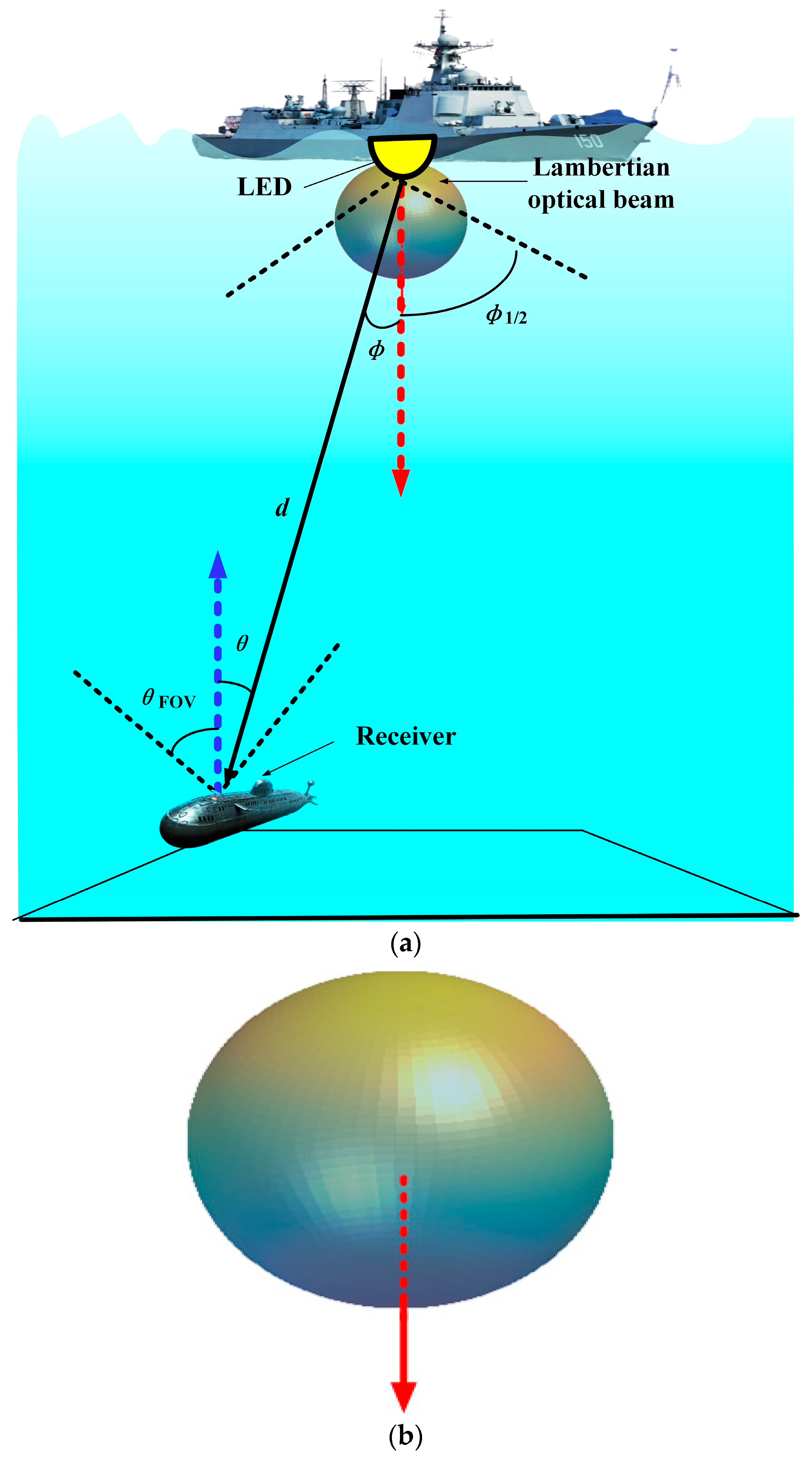
where describes the semi-angle at half-power of average transmitted optical source, which models the Lambertian optical beam width. Generally, the Lambertian index is set at 1, and then the respective 3D radiation pattern is shown in Figure 1, and the relevant UWOC application scenario based on this baseline Lambertian optical beam is illustrated for a 6G IoT network.
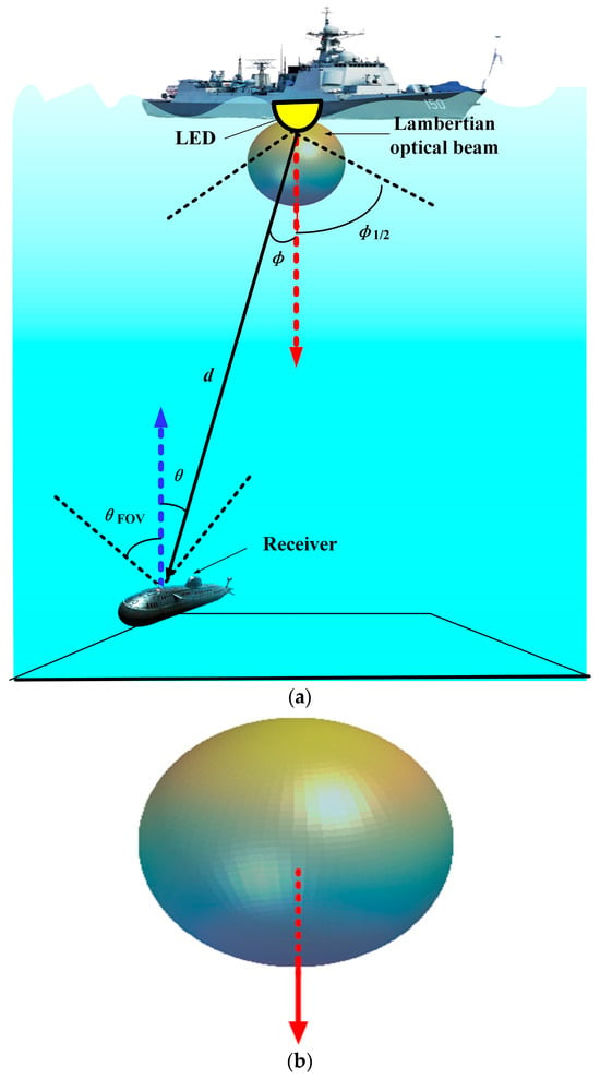
Figure 1.
Schematic of UWOC based on baseline Lambertian optical beam for 6G IoT network: (a) the respective application scenario, and (b) the relevant 3D beam pattern with the dashed line denoting the normal direction.
As for the receiver part of UWOC, is the effective area of the optical detector collecting the incident optical signal. And this area could be given by:
where denotes the active area of the optical detector, i.e., photodiode (PD), is the incident angle of the captured optical signal, and is the field of view (FOV) of the receiver. is the signal transmission gain of the optical filter and is the gain of the non-imaging optical concentrator, given by [7,9]:
where n is the internal refractive index of the optical concentrator. The reason of adopting the non-imaging over the imaging concentrator is that it offers a higher FOV and a relevant flexibility of beam misalignment between the optical source and the optical receiver. As for the respective UWOC application scenario based on the baseline Lambertian optical beam illustrated in Figure 1, the relevant optical channel gain is then given by:
where d denotes the distance between the optical source LED and the receiver, such that the received optical power could be expressed as follows:
where denotes the emitted optical power, and is the optical loss factor of the line of sight (LOS) communication links, which could be represented as [7,9]:
where denotes the beam extinction coefficient, i.e., the attenuation coefficient, and d denotes the distance between the optical source LED and the receiver. This attenuation coefficient is mainly dominated by absorption and scattering effects, which could be expressed as [7,9]:
where denotes the absorption coefficient of the water medium involved and denotes the scattering coefficient of the water medium involved. Both coefficients depend on the optical wavelength and the water type. Typically, the expression of and could be given as [14]:
and
where C denotes the chlorophyll concentration value of the water medium involved, is the absorption coefficient of pure water, and is the absorption coefficient for chlorophyll, which is a nondimensional number obtained via statistical analysis.
Based on the received optical power, the signal-to-noise ratio (SNR) could be given as [7,9]:
where denotes the responsivity of PD, q is the electron charge, is the noise figure, which is a function of the multiplication factor, denotes the receiver electrical bandwidth, is the Boltzmann constant, T denotes the temperature, and denotes the resistance. By substituting (5) and (7) into (11), the respective SNR of a UWOC system based on Lambertian beam configuration at the optical receiver could be renewed as:
2.2. Underwater Wireless Optical Communications Based on Distinct Non-Lambertian Optical Beam Configuration
Without loss of generality, as typical non-Lambertian optical beams, the LUXEON Rebel LED array and the NSPW345CS Nichia LED array were deliberately selected for the subsequent exploration of a UWOC system based on distinct non-Lambertian optical beam configurations in this work. The reason for this selection is that, on one hand, both beams have quite different spatial radiation characteristics compared with the conventional Lambertian optical beams, and on the other hand, both non-Lambertian beams are generated by commercially available LEDs, which makes this work applicable in engineering implementation.
Similar to the mentioned Lambertian beam, the spatial radiation intensity of the optical beam of the LUXEON Rebel LED array also conforms to rotational symmetry. According to the popular measurement and modeling work of commercially available LED optical beams in [10,12], the spatial radiation intensity of the LUXEON Rebel optical beam could be calculated using the following equation as a sum of Gaussian functions [10,12]:
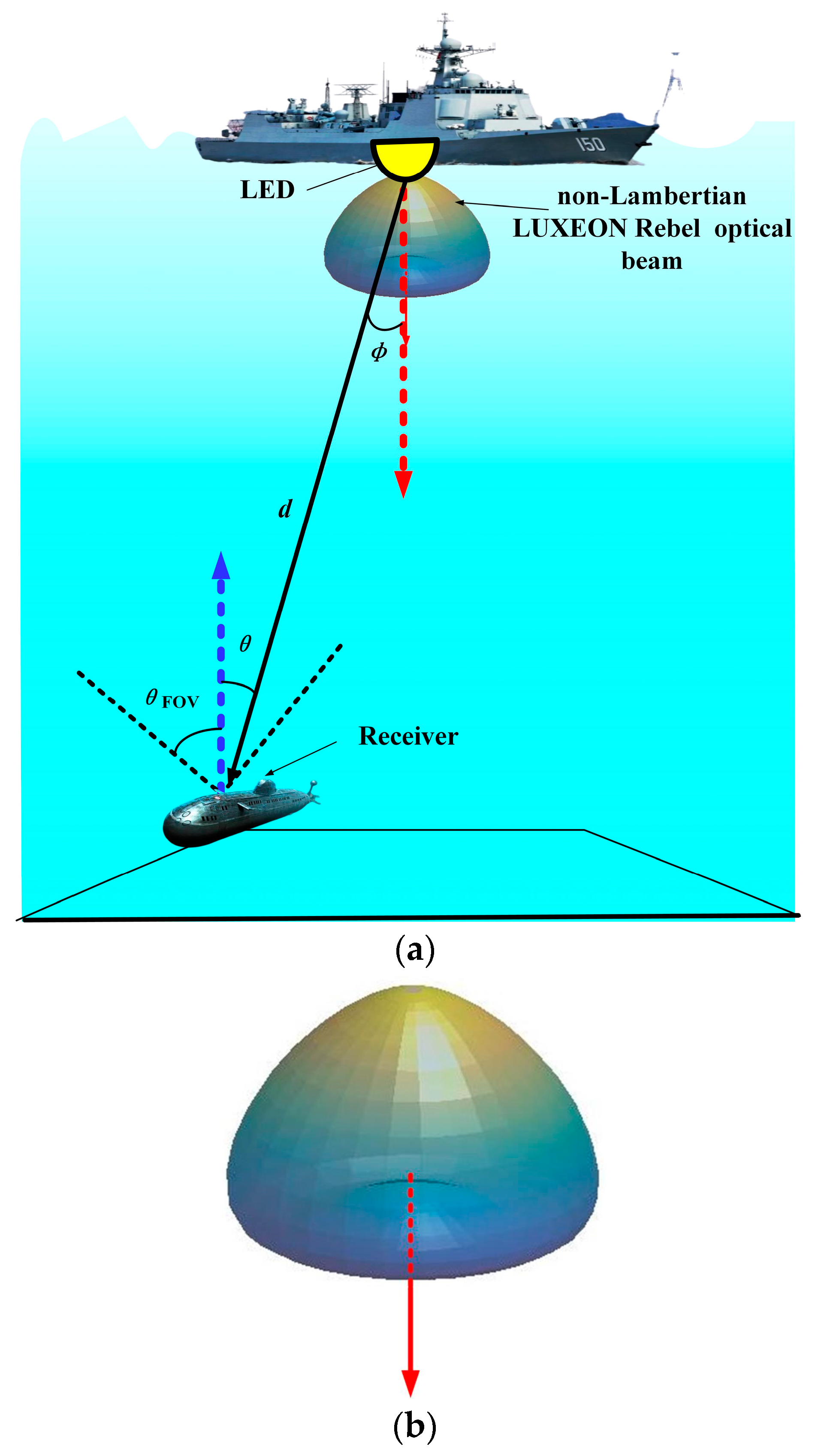
where denotes the emission angle, and N1 = 2 is the amount of Gaussian functions. Specifically, the values of the coefficients in this expression are as follows: = 0.76, = 0°, = 29°, = 1.10, = 45°, and = 21°. From the side view, Figure 2 illustrates the 3D beam patterns of this LUXEON Rebel non-Lambertian optical beam with rotational symmetry. Unlike the previous Lambertian optical beam, in this non-Lambertian case, the maximum emission intensity no longer appears at the normal direction, i.e., the red arrow direction, but at all directions with an irradiance angle of about 40°.
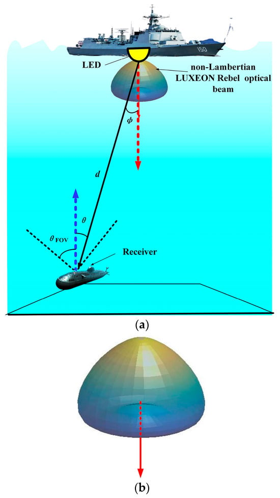
Figure 2.
Schematic of UWOC based on LUXEON Rebel optical beam for 6G IoT network: (a) the respective application scenario, and (b) the relevant 3D beam pattern with the dashed line denoting the normal direction.
In the typical underwater scenario based on the LUXEON Rebel optical beam illustrated in Figure 2, when the radiation characteristic of the optical source follows the LUXEON Rebel non-Lambertian beam, the relevant optical channel gain at the receiver is given as:
where denotes the power normalization factor of the LUXEON Rebel optical beam, which functions to ensure that the beam power radiated in all spatial directions is 1 W. In other words, unlike the conventional Lambertian beam pattern, this non-Lambertian beam pattern fails to realize the natural normalization since it is derived from the numerical fitting of measurement data of a commercially available LED product.
Similarly, based on the received optical power under this LUXEON Rebel optical beam configuration, the respective signal-to-noise ratio (SNR) of the UWOC system could be given as:
Furthermore, different from the well-discussed Lambertian beam and the above discussed LUXEON Rebel optical beam, the spatial radiation intensity of the asymmetric non-Lambertian beam depends on the elevation and azimuth angle of the emitted optical signal [10,12]. Without loss of generality, this work specifically investigates the non-Lambertian radiation pattern of the NSPW345CS Nichia type beam in a UWOC scenario. For convenience, NSPW is used to present this LED product type in this work. In other words, NSPW is not an acronym, but the product number for the NSPW345CS Nichia of one specific commercially available LED from the Nichia manufacturer. The respective radiation intensity could be calculated using the following equation [10,12]:
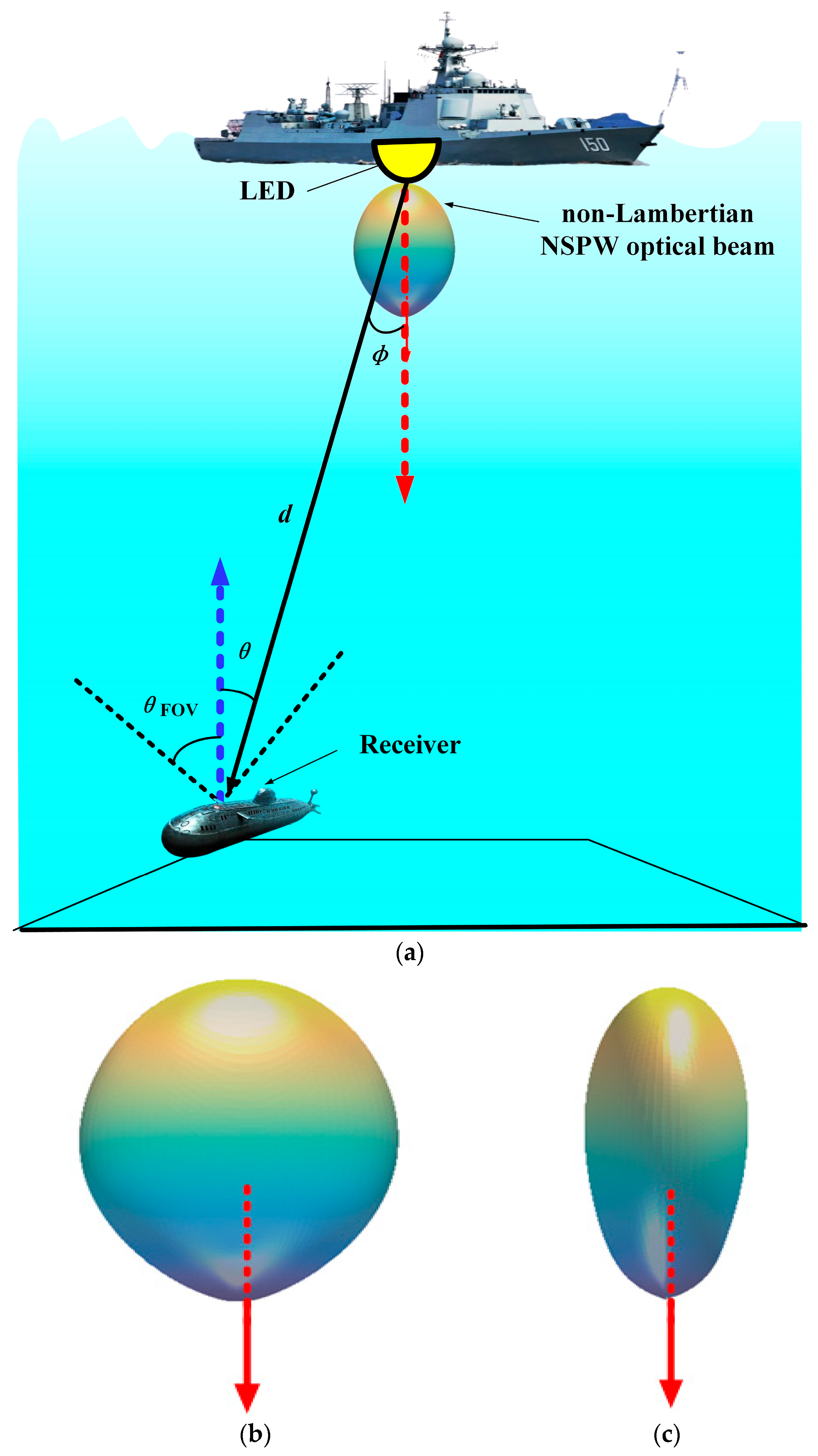
where α is the azimuth angle within the source plane. Specifically, the values of the coefficients in this expression are as follows: = 0.13, = 45°, = = 18°, = 1, = 0, = 38°, and = 22°. From the wide cross-section view angles, Figure 3 shows the 3D beam patterns of this asymmetric NSPW non-Lambertian beam. Moreover, Figure 3 shows the typical underwater scenario based on the asymmetric NSPW non-Lambertian beam. Under this beam configuration, the renewed optical channel gain expression could be given as:
where is the power normalization factor of this asymmetric NSPW non-Lambertian beam, which functions to ensure that the beam power radiated in all spatial directions is 1 W. Therefore, this means that this asymmetric NSPW non-Lambertian beam pattern fails to realize the natural normalization due to the fact that it is also derived from the numerical fitting of measurement data of a commercially available LED product.
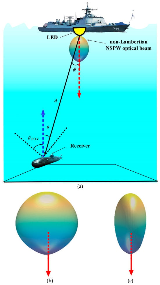
Figure 3.
Schematic of UWOC based on asymmetric NSPW non-Lambertian optical beam for 6G IoT network: (a) the respective application scenario, (b) the relevant 3D beam pattern from the wide side view with the dashed line denoting the normal direction, and (c) the relevant 3D beam pattern from the narrow side view with the dashed line denoting the normal direction.
Similarly, referring to (11) and (12), based on the received optical power under this asymmetric NSPW non-Lambertian optical beam configuration, the respective signal-to-noise ratio (SNR) of the UWOC system at the optical receiver should be renewed as:
For clarity, the explanations for the main symbols used in the mathematical modeling described in this section are included in Table 1.

Table 1.
Explanations for the main symbols used in the mathematical modeling described in Section 2.
3. Numerical Evaluation
In this section, a numerical analysis is carried out between the conventional Lambertian optical beam configuration and the emerging non-Lambertian optical beam configurations in terms of coverage performance of underwater wireless optical communications. Specifically, a typical underwater scenario under the water surface is considered, which is consistent with Figure 1a, Figure 2a, and Figure 3a. In addition, the main parameters involved are included in Table 1.
Specifically, a typical medium-size baseline underwater space is considered, which is consistent with Figure 3. In addition, the main parameters involved are included in Table 2.

Table 2.
Main parameter configuration.
Here, as for the Lambertian optical beam, the Lambertian index is set at 1 without loss of generality. And the emitted power of the transmitter and the LED Modulation bandwidth are determined as 10 W and 20 MHz, respectively, which could be attained using the typical commercially available LEDs. For the sake of simplicity, the optical filter gain is given as 1.
3.1. Effect of Different Water Type
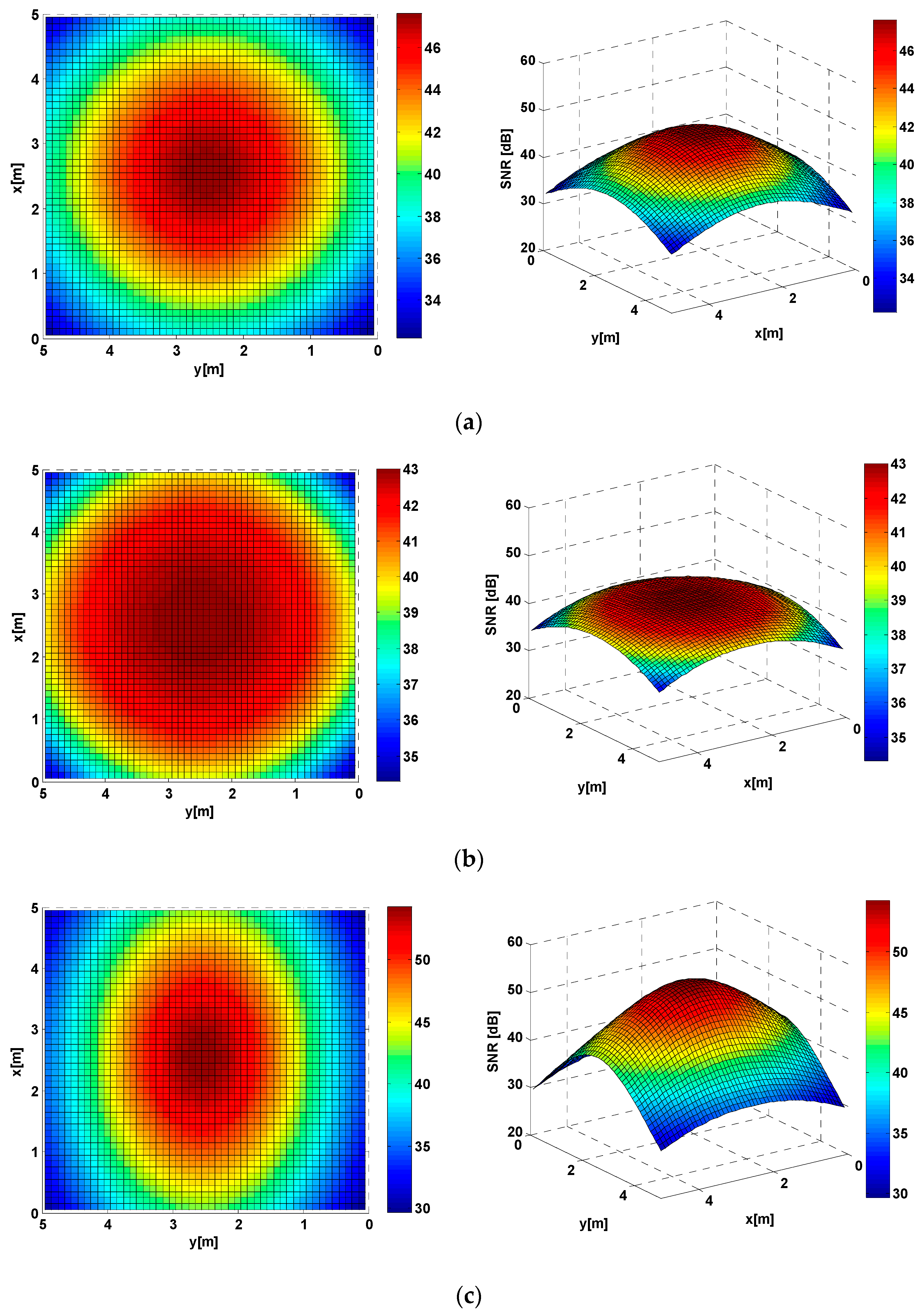
In this subsection, some numerical results are presented in order to quantify the impact of the optical beam configuration for the coverage performance of underwater wireless optical communications with different water types. Firstly, in the case of pure seawater, the underwater SNR spatial distribution on the receiver working plane for distinct optical beam configurations is illustrated in Figure 4. Specifically, for the baseline Lambertian optical beam configuration, an obviously rotational symmetry could be identified in the received SNR spatial distribution, due to this configuration’s azimuth angle-independent optical signal radiation. The corresponding SNR distribution ranges between 32.23 dB and 47.65 dB; the fluctuation amplitude is about 15.42 dB and the average SNR is about 41.13 dB. As for the LUXEON Rebel non-Lambertian optical beam configuration, a more uniform SNR spatial distribution is observed while the rotational symmetry in coverage is reserved, thanks to the bowl-shaped radiation pattern of this typical non-Lambertian optical beam. Moreover, the respective fluctuation amplitude of the SNR distribution is dramatically reduced to 8.71 dB, with the SNR distribution ranging between 34.31 dB and 43.02 dB, and the average SNR is changed to about 40.77 dB. In addition, as for the NSPW non-Lambertian optical beam configuration, more intense SNR spatial fluctuation is illustrated because of the unique rotational asymmetry in the radiation pattern at the optical source end. The relevant SNR fluctuation amplitude is increased to 24.60 dB, with the SNR distribution ranging between 29.71 dB and 54.31 dB, and the average SNR is increased to about 42.83 dB.
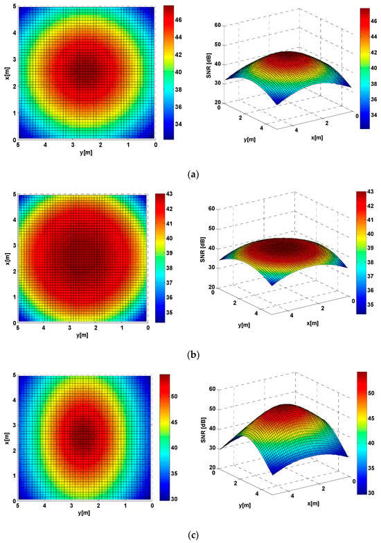
Figure 4.
Underwater SNR spatial distribution of pure seawater for distinct optical beam configurations: (a) baseline Lambertian optical beam configuration, (b) LUXEON Rebel non-Lambertian optical beam configuration, and (c) NSPW non-Lambertian optical beam configuration.
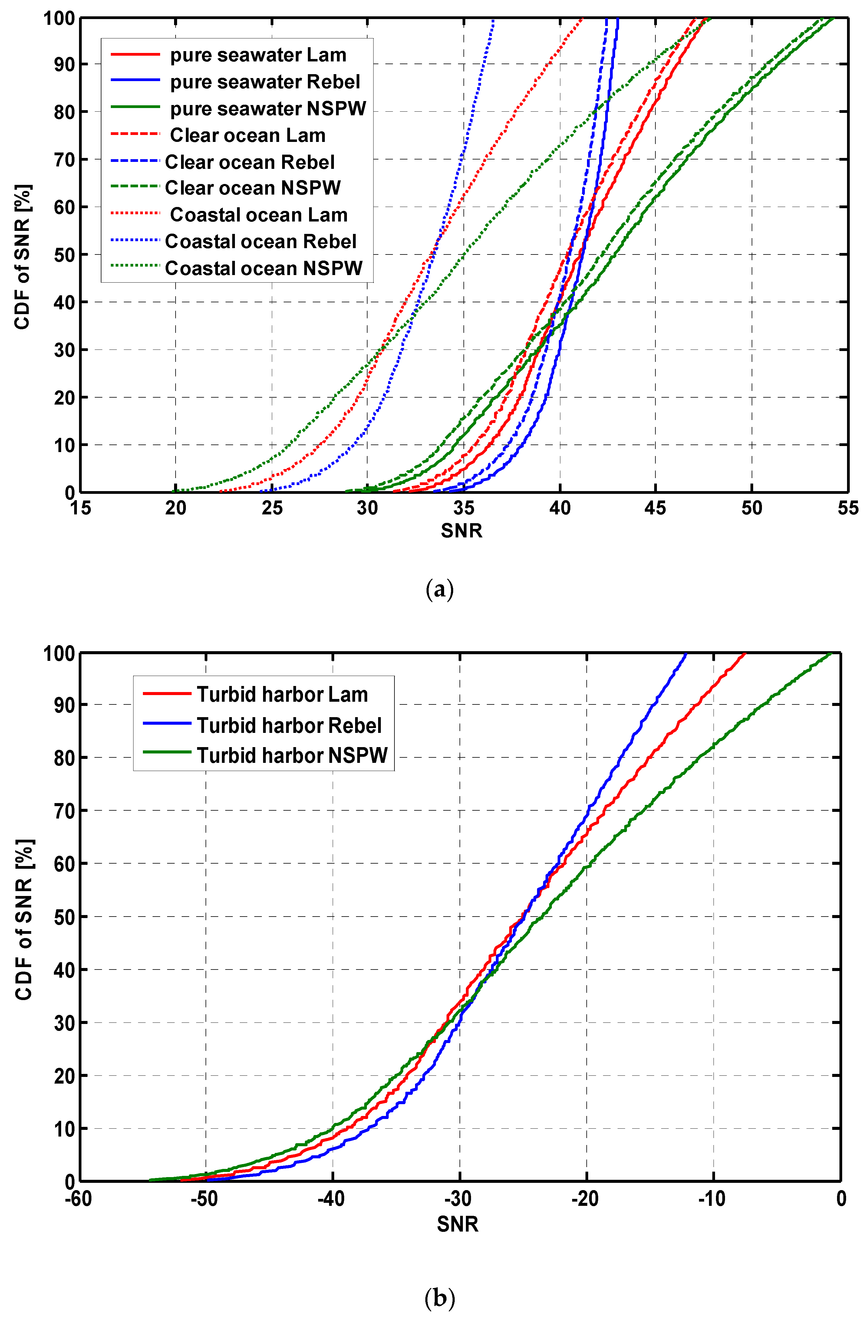
In Figure 5, the cumulative distribution functions (CDFs) of the underwater SNR spatial distribution of different water types for distinct optical beam configurations are illustrated separately. For up to 90% of receiver positions under the Lambertian UWOC configuration, the SNR is more than 36.31 dB, while the corresponding values of the LUXEON Rebel non-Lambertian configuration and the NSPW345CS non-Lambertian configuration are changed to 38.02 dB and 34.58 dB, respectively. Therefore, the proposed LUXEON Rebel non-Lambertian UWOC configuration is capable of improving the weak coverage domain of the typical UWOC application scenario. When the water type is replaced by clear seawater, this performance metric is slightly reduced to 35.56 dB for the Lambertian UWOC configuration, while the respective metric is slightly reduced to 37.28 dB and 33.88 dB for the LUXEON Rebel non-Lambertian configuration and the NSPW345CS non-Lambertian configuration, although the SNR fluctuation amplitude and trend for each optical beam configuration is inherited from the original pure seawater condition to the discussed clear seawater condition.
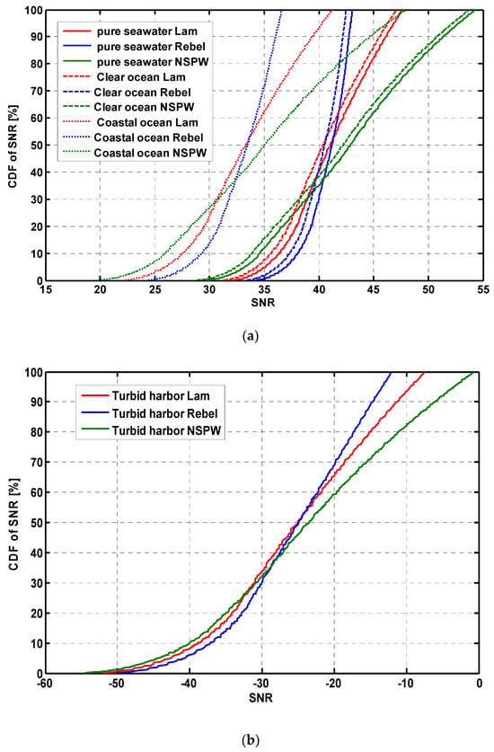
Figure 5.
CDF of underwater SNR spatial distribution of different water types for distinct optical beam configurations: (a) the first three water types, and (b) the last water type.
Furthermore, once the water type is changed to coastal seawater, a significant SNR loss could be observed for the coverage performance of the three optical beam configurations under study. Specifically, for the Lambertian UWOC configuration, the average SNR is reduced to about 33.38 dB, while for up to 90% of receiver positions, the SNR is no less than 27.49 dB. As for the LUXEON Rebel non-Lambertian configuration, the average SNR is reduced to about 33.02 dB, while for up to 90% of receiver positions, the SNR is no less than 29.21 dB. Moreover, for the NSPW non-Lambertian configuration, the average SNR is reduced to about 35.09 dB, while for up to 90% of receiver positions, the SNR is no less than 25.91 dB.
As shown in Figure 5b, for the last water type, given the higher scattering coefficient of turbid seawater, almost all received SNR values are below −10 dB for the discussed UWOC coverage with the above-mentioned distinct optical beam configurations, and the difference in CDF characteristics is deeply reduced, which means that the serious absorption and scattering impact of turbid seawater type dominates the SNR spatial performance to a larger extent.
3.2. Effect of Receiver FOV
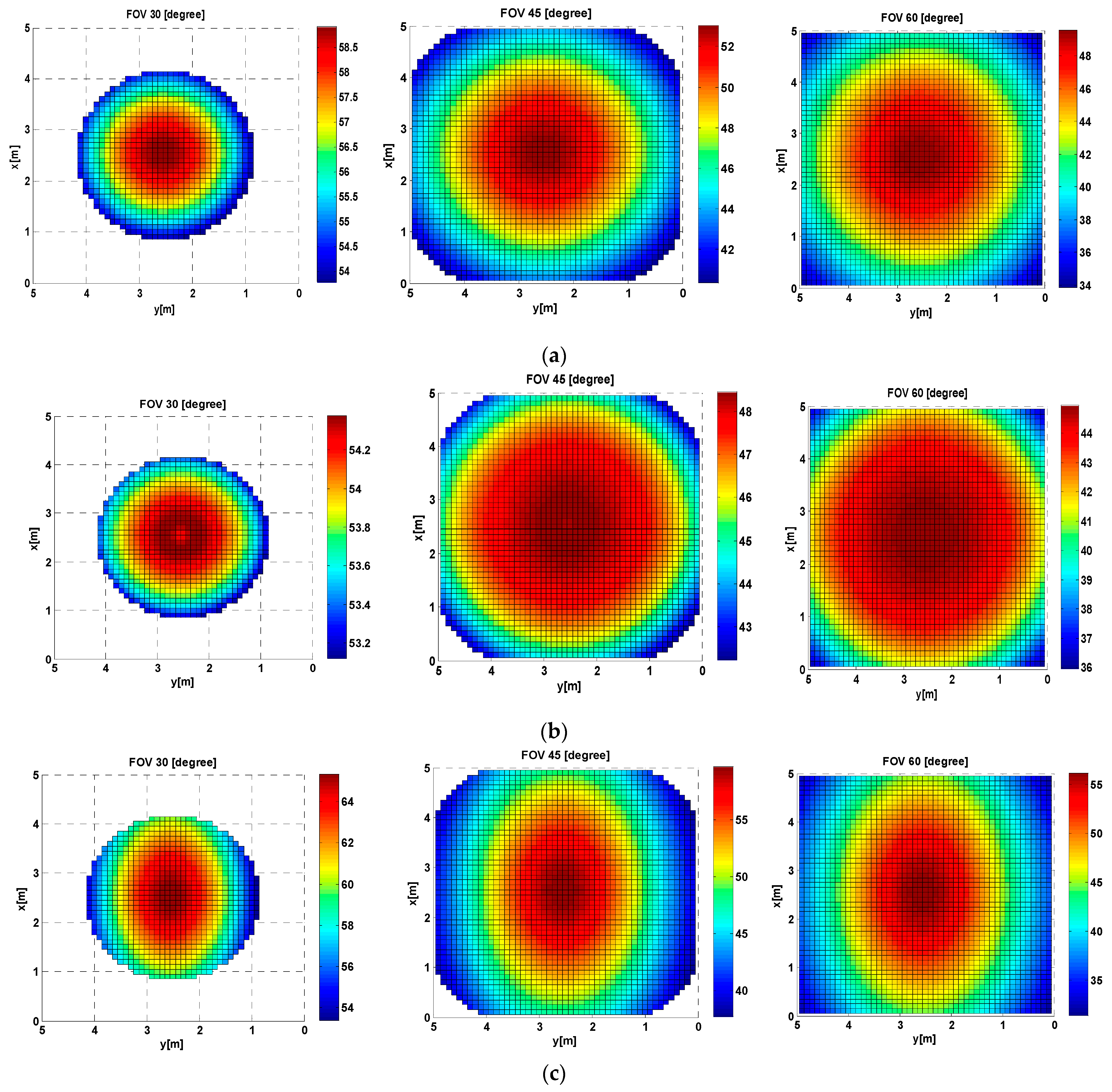
To investigate the effect of receiver FOV on the performance of UWOC coverage, three FOV settings, i.e., 30°, 45°, and 60° are introduced to the three UWOC systems with distinct optical beam configurations in a clear seawater environment, as shown in Figure 6. In the case of the 30° FOV, only the central domain, i.e., 37.1%, of the receiver working plane could capture the optical signal, which means that only limited mobility support could be obtained in this situation for all three optical beam configurations. When FOV is increased to 45°, only the four limited corner domains fail to capture the expected optical signal, which means that the coverage could be supported for up to 95.2% of the receiver working plane for all three beam configurations. Once FOV is increased to 60°, total mobility support could be assured over the receiver working plane, independent of the optical beam configurations under study.
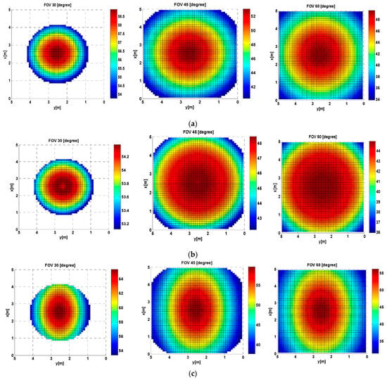
Figure 6.
Underwater SNR spatial distribution of different receiver FOVs for distinct optical beam configurations: (a) baseline Lambertian optical beam configuration, (b) LUXEON Rebel non-Lambertian optical beam configuration, and (c) NSPW non-Lambertian optical beam configuration.
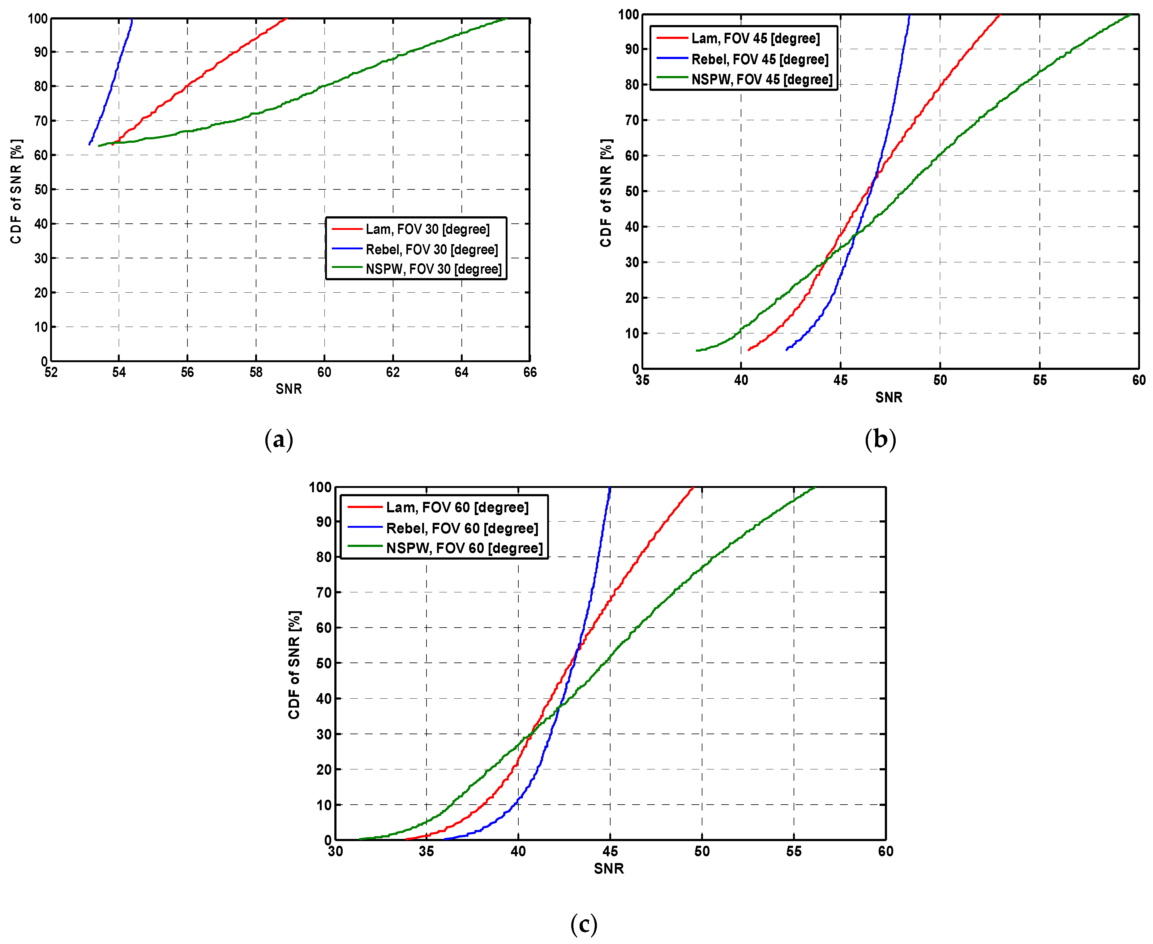
When FOV is increased to 60°, this performance metric will be further reduced to about 42.96 dB, 42.60 dB, and 44.66 dB, which objectively reflects the SNR loss for the enhancement of mobility support. Accordingly, the CDF of underwater SNR spatial distribution of different receiver FOVs for distinct optical beam configurations is shown in Figure 7.
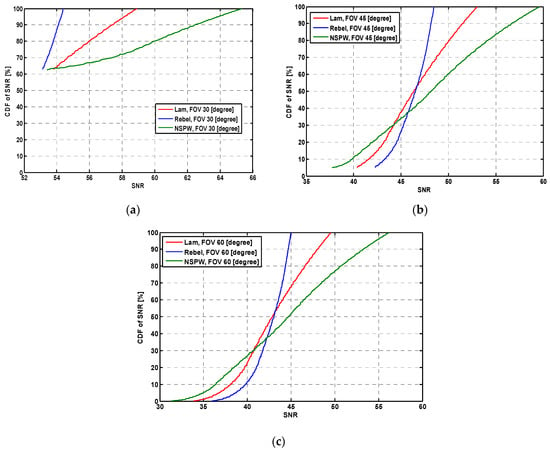
Figure 7.
CDF of underwater SNR spatial distribution of different receiver FOVs for distinct optical beam configurations: (a) FOV = 30°, (b) FOV = 45°, and (c) FOV = 60°.
3.3. Effect of Receiver Depth
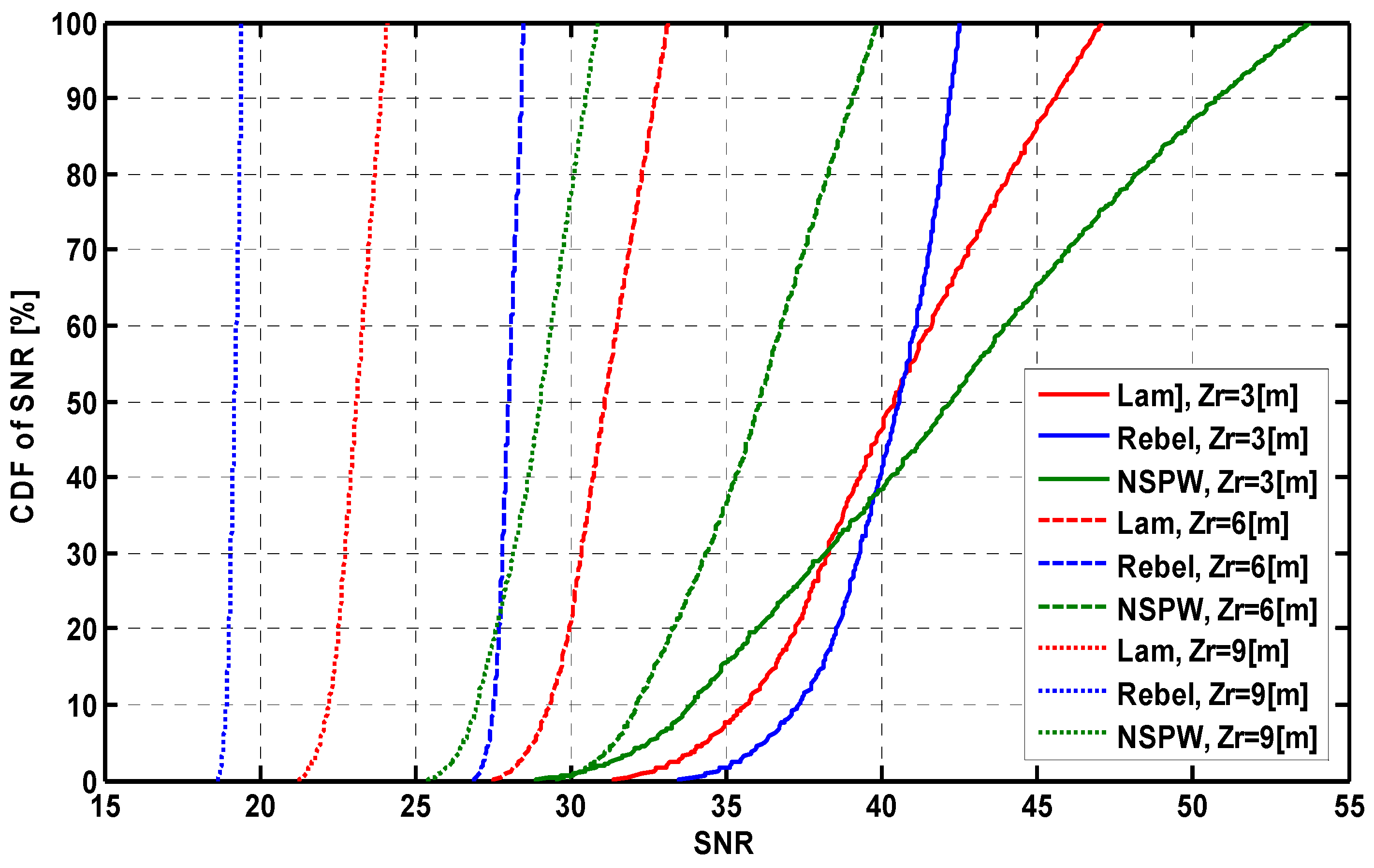
To investigate the effect of receiver depth on the performance of UWOC coverage, three receiver depth settings, i.e., 3.0 m, 6.0 m, and 9.0 m are introduced to the three UWOC systems with distinct optical beam configurations in a clear seawater environment, as shown in Figure 8. In the case of the 3.0 m receiver depth, the average SNR is about 40.48 dB, 40.11 dB, and 42.18 dB for the baseline Lambertian optical beam configuration, LUXEON Rebel non-Lambertian optical beam configuration, and NSPW non-Lambertian optical beam configuration, and the corresponding SNR dynamic range is about 15.71 dB (i.e., 31.40 dB~47.11 dB), 8.99 dB (i.e., 33.48 dB~42.47 dB), and 24.9 dB (i.e., 28.88 dB~53.78 dB). Once the receiver depth is increased to 6.0 m, this average SNR metric is reduced to about 31.04 dB, 27.97 dB, and 35.8 dB for the three configurations under study, while the corresponding SNR dynamic range is about 5.61 dB (i.e., 27.52 dB~33.13 dB), 1.58 dB (i.e., 26.87 dB~28.45 dB), and 10.33 dB (i.e., 29.55 dB~39.88 dB). When the receiver depth is further increased to 9.0 m, this average SNR performance metric will be further reduced to about 23.08 dB, 19.17 dB, and 28.85 dB, which objectively reflects the superiority of the NSPW non-Lambertian optical beam configuration against the receiver depth effect.
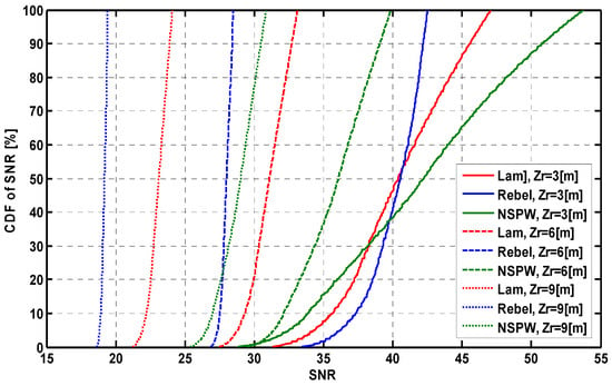
Figure 8.
CDF of underwater SNR spatial distribution of different receiver depths for distinct optical beam configurations.
3.4. Effect of Receiver Aperture Size
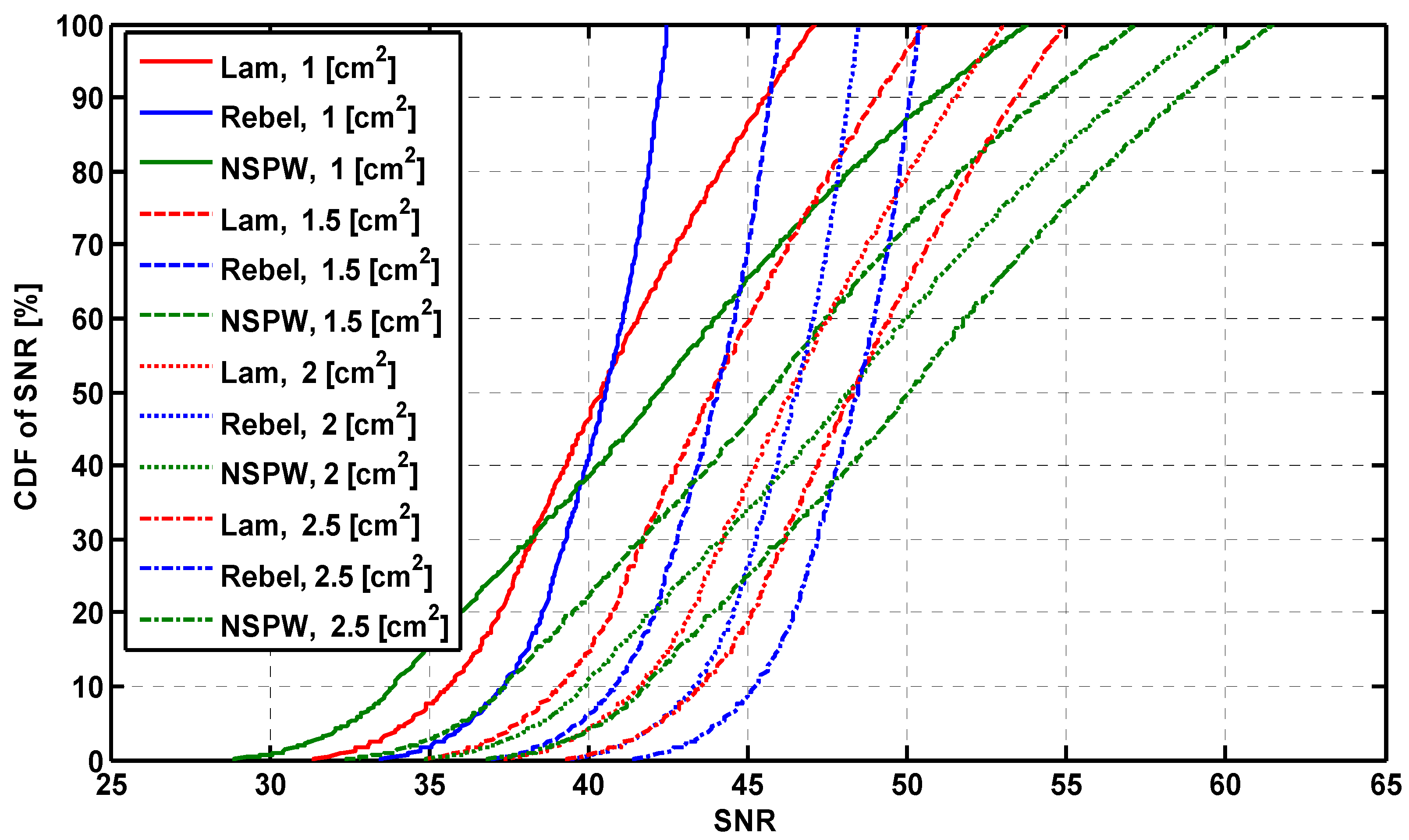
To investigate the effect of receiver aperture size on the performance of UWOC coverage, four physical areas of PD settings, i.e., 1.0 cm2, 1.5 cm2, 2.0 cm2, and 2.5 cm2, are introduced to the three UWOC systems with distinct optical beam configurations in a clear seawater environment, as shown in Figure 9. According to Equations (5), (14) and (17), the increase in receiver aperture size will be beneficial to the increase in optical channel gain for each optical beam configuration. Once the receiver aperture size is increased to 1.5 cm2 from the original 1.0 cm2, the average SNR is enhanced to about 43.98 dB, 43.61 dB, and 45.67 dB, respectively, from the original about 40.48 dB, 40.11 dB, and 42.18 dB of the baseline Lambertian optical beam configuration, LUXEON Rebel non-Lambertian optical beam configuration, and NSPW non-Lambertian optical beam configuration. The corresponding average SNR gain provided by this 0.5 cm2 enlargement in receiver aperture size is about 3.50 dB, 3.50 dB, and 3.49 dB, respectively. Furthermore, when the receiver aperture size is further increased to 2.0 cm2 from 1.5 cm2, the average SNR is enhanced to about 46.45 dB, 46.09 dB, and 48.14 dB, respectively, while the corresponding average SNR gain is about 2.47 dB, 2.48 dB, and 2.47 dB for the three configurations under study. Once the receiver aperture size is increased to 2.5 cm2, the achieved average SNR gain is further reduced to about 1.92 dB, 1.91 dB, and 1.91 dB for the three beam configurations, which means that the SNR gain amplitude provided by the aperture size enlargement is gradually reduced with increasing aperture size.
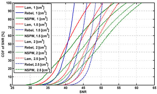
Figure 9.
CDF of underwater SNR spatial distribution of different receiver aperture sizes for distinct optical beam configurations.
It is clear that, as shown in this work, the potential non-Lambertian beam configurations provide a novel design dimension, i.e., a spatial optical beam dimension, for the development of underwater wireless optical communication techniques for future 6G IoT networks. Specifically, specific non-Lambertian beam configurations with rotational symmetry could enhance coverage uniformity, which could reduce the received optical signal fluctuation for the receiver moving to the coverage cell edge from the cell central area in underwater environments. In addition, in this work, it is numerically verified that specific non-Lambertian beam configurations without rotational symmetry could provide unique coverage performance with spatial selectivity, even azimuth selectivity, which provide the opportunity and capability to concentrate more coverage intensity and better transmission quality to certain users, and reduce the waste of optical coverage in meaningless spatial directions to some extent.
In actual fact, the investigation of 6G underwater IoT networks is still an open topic, and the 6G communication standards are also under active discussion from the academic and industry communities. Up to now, almost all explorations of LED-based underwater wireless optical communications have been limited to the well-discussed Lambertian beam configurations, which could not guide or support the upcoming 6G communication standards nor adapt to diverse non-Lambertian underwater application scenarios. They thus fail to open up novel and exciting research opportunities including underwater optical beam selection, underwater optical beam management, underwater optical beam switching, underwater optical beam cooperation, underwater optical beam steering, and so on. It is clear that this work fills these gaps to some extent and will provide fundamental support for 6G underwater IoT networks to address challenging application scenarios with heterogeneous optical beam configurations and utilize novel and attractive optical beam dimensions to enhance underwater communication performance.
4. Conclusions
This work is motivated by the limitation of the conventional UWOC research paradigm based on the well-discussed Lambertian optical beam, which could not address the investigations of UWOC systems based on emerging non-Lambertian optical beams. In this work, commercially available non-Lambertian sources are introduced to configure the UWOC transmitter, and the corresponding underwater coverage performance is numerically evaluated for future 6G marine IoT environments. In the non-Lambertian UWOC configurations in question, on the receiver working plane, for up to 90% of receiver positions, the SNR is more than 38.02 dB, while the corresponding value of the baseline Lambertian UWOC configuration is just about 36.31 dB. In addition, this performance metric for these two beam configurations will be ultimately reduced to about 29.21 dB and 27.49 dB, respectively, once the water type is changed to coastal seawater for the UWOC environment. In future work, the exploration of non-Lambertian underwater wireless optical communications will be extended to beam switching, beam combination, dynamic beam configuration, resource allocation, reconfigurable multiple-input multiple-output, and other enabling techniques. Moreover, we will push the relevant experimental work forward to illustrate underwater coverage with distinct optical beam configurations.
Author Contributions
J.D. determined the theme and structure of the article, provided professional knowledge in the field of visible light communications, wrote and modified the article, and replied to comments from editors and reviewers. C.-L.I. provided theoretical knowledge of mobile communication and wireless communication. J.W. performed the literature search, participated in the discussion, and wrote some of the content. J.S. performed the literature search, participated in the discussion, and wrote some of the content. All authors have read and agreed to the published version of the manuscript.
Funding
This work was supported in part by the National Natural Science Foundation of China (Grants No. 62061043), the Tianshan Cedar Project of Xinjiang Uygur Autonomous Region (Grants No. 2020XS27), and the High-level Talents Introduction Project in Autonomous Region (Grants No. 042419004).
Institutional Review Board Statement
Not applicable.
Informed Consent Statement
Not applicable.
Data Availability Statement
Data are contained within the article.
Conflicts of Interest
The authors declare no conflicts of interest.
References
- Chowdhury, M.Z.; Hossan, M.T.; Islam, A.; Jang,, Y.M. A comparative survey of optical wireless technologies: Architectures and applications. IEEE Access 2018, 6, 9819–9840. [Google Scholar] [CrossRef]
- Hamza, A.S.; Deogun, J.S.; Alexander, D.R. Classification framework for free space optical communication links and systems. IEEE Commun. Surv. Tuts. 2019, 21, 1346–1382. [Google Scholar] [CrossRef]
- Zhang, J.; Gao, G.; Wang, B.; Guan, X.; Yin, L.; Chen, J.; Luo, B. Background Noise Resistant Underwater Wireless Optical Communication Using Faraday Atomic Line Laser and Filter. J. Light. Technol. 2022, 40, 63–73. [Google Scholar] [CrossRef]
- Zhou, H.; Zhang, M.; Wang, X.; Ren, X. Design and Implementation of More Than 50m Real-Time Underwater Wireless Optical Communication System. J. Light. Technol. 2022, 40, 3654–3668. [Google Scholar] [CrossRef]
- Ijeh, I.C.; Haddad, O.; Khalighi, M.A. Ergodic Capacity of a Vertical Underwater Wireless Optical Communication Link Subject to Misalignment. In Proceedings of the 2022 4th West Asian Symposium on Optical and Millimeter-Wave Wireless Communications (WASOWC), Tabriz, Iran, 12–13 May 2022; IEEE: New York, NY, USA, 2022. [Google Scholar]
- Pandey, P.; Matta, G.; Aggarwal, M. Investigation of photodetector responsivity on the performance of underwater optical wireless communication systems. In Proceedings of the OCEANS 2022, Chennai, India, 21–24 February 2022; IEEE: New York, NY, USA, 2022. [Google Scholar]
- Liu, A.; Yuan, Y.; Yin, H.; Zhao, H.; Fu, X. Optimization of LED Array Spatial Coverage Characteristics in Underwater Wireless Optical Communication. J. Mar. Sci. Eng. 2023, 11, 253. [Google Scholar] [CrossRef]
- Wang, X.; Luo, H.; Yang, Y.; Ruby, R.; Wu, K. Underwater Real-time Video Transmission via Optical Channels with Swarms of AUVs. In Proceedings of the 2021 IEEE 27th International Conference on Parallel and Distributed Systems (ICPADS), Beijing, China, 7–9 February 2022; IEEE: New York, NY, USA, 2022. [Google Scholar]
- Amalia, A.I.; Hambali, A.; Pamukti, B. Performance Analysis of on-off Keying Modulation on Underwater Visible Light Communication. In Proceedings of the 2020 6th International Conference on Science and Technology (ICST), Yogyakarta, Indonesia, 7–8 September 2020. [Google Scholar]
- Moreno, I.; Sun, C.-C. Modeling the radiation pattern of LEDs. Opt. Exp. 2008, 16, 1808–1819. [Google Scholar] [CrossRef] [PubMed]
- Nakagawa, M. Fundamental analysis for visible-light communication system using LED lights. IEEE Trans. Consum. Electron. 2004, 50, 100–107. [Google Scholar]
- Ding, J.; Chih-Lin, I.; Xu, Z. Indoor optical wireless channel characteristics with distinct source radiation patterns. IEEE Photonics J. 2016, 8, 7900115. [Google Scholar] [CrossRef]
- Ding, J.; Zhao, K.; Liu, S. Exploring the Effect of optical beams on hybrid VLC/RF transmission characteristics. Photonics 2023, 10, 185. [Google Scholar] [CrossRef]
- Yang, C.; Yang, F. Communication Interruption Analysis for Air-water Wireless Optical Communication. In Proceedings of the 2023 International Wireless Communications and Mobile Computing (IWCMC), Marrakesh, Morocco, 19–23 June 2023. [Google Scholar]
Disclaimer/Publisher’s Note: The statements, opinions and data contained in all publications are solely those of the individual author(s) and contributor(s) and not of MDPI and/or the editor(s). MDPI and/or the editor(s) disclaim responsibility for any injury to people or property resulting from any ideas, methods, instructions or products referred to in the content. |
© 2024 by the authors. Licensee MDPI, Basel, Switzerland. This article is an open access article distributed under the terms and conditions of the Creative Commons Attribution (CC BY) license (https://creativecommons.org/licenses/by/4.0/).

