Article

Design Principles for Laser-Printed Macrofluidics

1
Department of Plant Sciences, The Robert H. Smith Faculty of Agriculture, Food and Environment, The Hebrew University of Jerusalem, Rehovot 7610001, Israel
2
Sammy Offer School of Communications, Reichman University, Herzliya 4610101, Israel
3
Faculty of Medicine, School of Pharmacy, Institute for Drug Research (IDR), The Hebrew University of Jerusalem, Jerusalem 9112102, Israel
*
Authors to whom correspondence should be addressed.
Inventions 2024, 9(4), 68; https://doi.org/10.3390/inventions9040068
Submission received: 29 April 2024 / Revised: 11 June 2024 / Accepted: 20 June 2024 / Published: 26 June 2024
(This article belongs to the Section Inventions and Innovation in Biotechnology and Materials)

Abstract

:
This paper presents a novel method for fabricating fluidic circuits using laser printing technology. The method allows for rapid prototyping of macrofluidic devices with control over fluid manipulation and environmental conditions. We employed a high-resolution laser cutter to etch fluidic channels into various substrates, optimizing parameters such as laser power, speed, and substrate material. Our results demonstrate excellent performance in controlling fluid flow and maintaining environmental conditions, handling a wide range of fluids and flow rates. The devices were tested in multiple settings such as with high school students and in research laboratories in universities. We tested the laser-printed macrofluidcs mechanically for durability. We present previous works in microbiology with plants, microbial, and mammalian cell lines showing reliable operation with minimal leakage and consistent fluid dynamics. The versatility and scalability of this approach make it a promising tool for advancing research and innovation in fluidics, providing a robust platform for growing, manipulating, and experimenting with diverse biological systems from cells to whole organisms. We conclude that laser-printed macrofluidics can significantly contribute to fields such as biomedical research, synthetic biology, tissue engineering, and STEM education.

1. Introduction

Fluidic circuits constitute fundamental components in a myriad of scientific and engineering endeavors, spanning from chemical analysis to biological research and drug discovery. Traditional approaches to fabricate microfluidic devices often involve intricate procedures such as photolithography, soft lithography, or micro-machining, and 3D printing which can be both time-consuming and costly [1,2]. These systems have been in research since the 1950s and have been used coupled with sensors, micro pumps, and microscopy [3,4,5,6]. Recent advancements in this domain have introduced digital microfluidics, a technology devoid of traditional channels, wherein liquids are manipulated on an electrically charged surface, proving particularly advantageous in applications like DNA sequencing library preparation [7,8]. The macrofluidics devices we present here operate at volumes of 1–2000 mL, while microfluidic devices typically operate in the scale of 0.01–1 mL. Macrofluidic systems are often made by converting existing equipment such a a 50 mL tube [9] or by 3D printing [10]; in both cases, evaluation and methods for sterilization, durability, and compatibility with the bioprocess are required.
In the realm of lab-scale bio-process prototyping, macrofluidics emerges as a versatile domain encompassing flexible tubes, glass and plastic apparatuses, sensors, actuators, as well as 3D-printed and machined components. Each of these components is uniquely tailored to diverse applications [11,12,13,14,15,16,17,18]. Critical elements of a macrofluidic device include chambers, channels, valves, as well as actuators for fluid manipulation, temperature control, and filtration. However, paramount among these requirements is the necessity for sterility, demanding most components to be autoclavable or sterilizable by alternative means. Despite research and development in microfluidics fabrication, actuation, and utilization [3], macrofluidics generally uses tubes and vessels from glass, plastic, and off-the-shelf components such as peristaltic pumps and other repurposed sensors and actuators [19].
Single-use bioreactors represent a paradigm shift in bioprocessing technology, offering a cost-effective and scalable alternative to traditional stainless steel or glass bioreactors. Their disposability, coupled with pre-use sterilization procedures, obviates the need for post-use sterilization, streamlining bioprocessing workflows and enhancing operational efficiency [20,21,22,23].
With applications extending into food production, such as utilizing microbial cells for cow milk protein synthesis, there arises a pressing need for increased fermentation capacity to meet global demands [24]. Similarly, analogous to agricultural practices, scaling out may prove favorable over scaling up, facilitated by fluidic modeling and consideration of large-scale forces acting on cells, liquids, as well as nutrient and waste molecule diffusion across culture environments [25,26,27].
As DIY tools democratize science through the creation of experimental apparatuses [28,29,30,31], fluidic systems are designed to democratize food and material production via decentralized fermentation [32,33]. Central to fermentation is sterility, followed closely by utility. In our work with “My First Biolab”, we employed laser-printed macrofluidics to enable K-12 students to engage in microbial fermentation without the need for gloves or pipettes, thanks to a fully encapsulated experimental setup [34,35].
Aeration, agitation, and monitoring are pivotal features for automating cell culture in bioreactor systems. Previous studies have demonstrated programmable air pumps, peristaltic pumps, and optical sensors adapted for laser-printed macrofluidic devices, facilitating the cultivation of bacteria and mammalian cells both in suspension and on scaffolds [34,35].
In recent years, additive manufacturing techniques have emerged as promising alternatives, allowing for rapid prototyping of fluidic systems. Among these techniques, laser welding of macrofluidics offers unique advantages in terms of versatility, precision, scalability, and speed, making it an ideal rapid prototyping tool for biotechnology applications and STEM education through inquiry-based learning [36]. Despite the high cost of laser equipment, the affordability and global availability of materials render this method accessible on a broad scale.

Applications

Laser-printed macrofluidics have diverse applications across various fields, including:
  • Biomedical Research: The ability to control fluid flow, temperature, and agitation makes laser-printed macrofluidics ideal for culturing cells, conducting drug screening assays, and studying biochemical reactions.
  • Chemical Engineering: Macrofluidic devices can be used for process monitoring and optimization in chemical manufacturing processes, including mixing, reaction kinetics, and separation techniques.
  • Environmental Monitoring: Laser-printed macrofluidics enable on-site analysis of environmental samples, such as water quality testing and air pollution monitoring.
In this paper, we present a novel approach for fabricating large fluidic circuits using laser printing technology, providing a potential solution for a bottleneck in experimentation that would otherwise require sourcing multiple materials such as glass and plastic and methods such as 3D printing or injection molding, in addition to sterilization and biocompatibility tests. Our method leverages thermoadhesive films to create customizable fluidic channels that can be combined with non-invasive sensors and actuators. The resulting macrofluidic devices enable precise control over fluid manipulation, temperature regulation, and environmental conditions, while their sterility makes them ideal for a wide range of applications in scientific research and even in education, prototyping, and in industrial processes.

2. Materials and Methods

2.1. Fabrication Method

As elaborated in [35], a Universal Laser Systems, Inc. model VLS 3.6 laser cutter, Scottsdale, AZ, USA equipped with a 60 W CO2 laser featuring programmable focus was employed to cut and weld a polyethylene–polyamide (PAPE) multilayer thermoadhesive film conventionally utilized in food packaging. The thermoplastic film bilayer comprised of multilayered PAPE sourced from Plastopil (HaZore’a, Israel), with a total thickness of 140 µm, consisting of two 70 µm layers closely adhered together, is a modified version of PLASTOBARR XU, Plastopil Hazorea, IsraelFor welding the film bilayer, the laser cutter was configured to deliver a power output ranging from 12 to 24 watts at maximum speed. The film was positioned within the laser cutter, and the laser beam was focused onto the film layers at z = 0.2 mm for cutting and 8 mm for welding. Subsequently, the laser traversed the thermoplastic film bi-layer continuously, generating sufficient heat to fuse the two film layers seamlessly. Under optimal conditions, this methodology facilitated precise and dependable welding and cutting of the PAPE film bilayer with minimal heat-induced damage. The resulting welds exhibited robustness and impermeability, rendering them suitable for integration into fluidic systems, thereby serving as viable components for fluidic devices. The ultimate tensile strength was evaluated as the load at failure divided by the cross-sectional area for different laser settings. Designs for macrofluidic devices can be generated on any CAD software. In this study we used Adobe Illustrator version 28.5 to design both Raster or Vector files. Generally, Vector files will allow for a faster fabrication time; for example, in a 30 × 60 cm laser bed as the one we used, it will take 1–5 min to weld and cut a Vector file.

2.2. Fabrication and Production Process

The fabrication process for laser-printed macrofluidics involves several steps:
  • Design on CAD software.
  • Visual inspection of the PAPE film.
  • Introduction of the material into the laser cutter.
  • The fluidic circuit design is transferred to the thermoadhesive film using a laser printing system by welding and cutting.
  • The laser selectively heats the film, causing it to adhere to the substrate and create fluidic channels, ports, chambers, and other fluidic elements for the process it was designed for.
  • Fitting the printed fluidic on a vertical holder or other vertical arrangement.
  • Introducing liquids and gasses, applying actuation if needed, and monitoring the experiment with or without sensors.

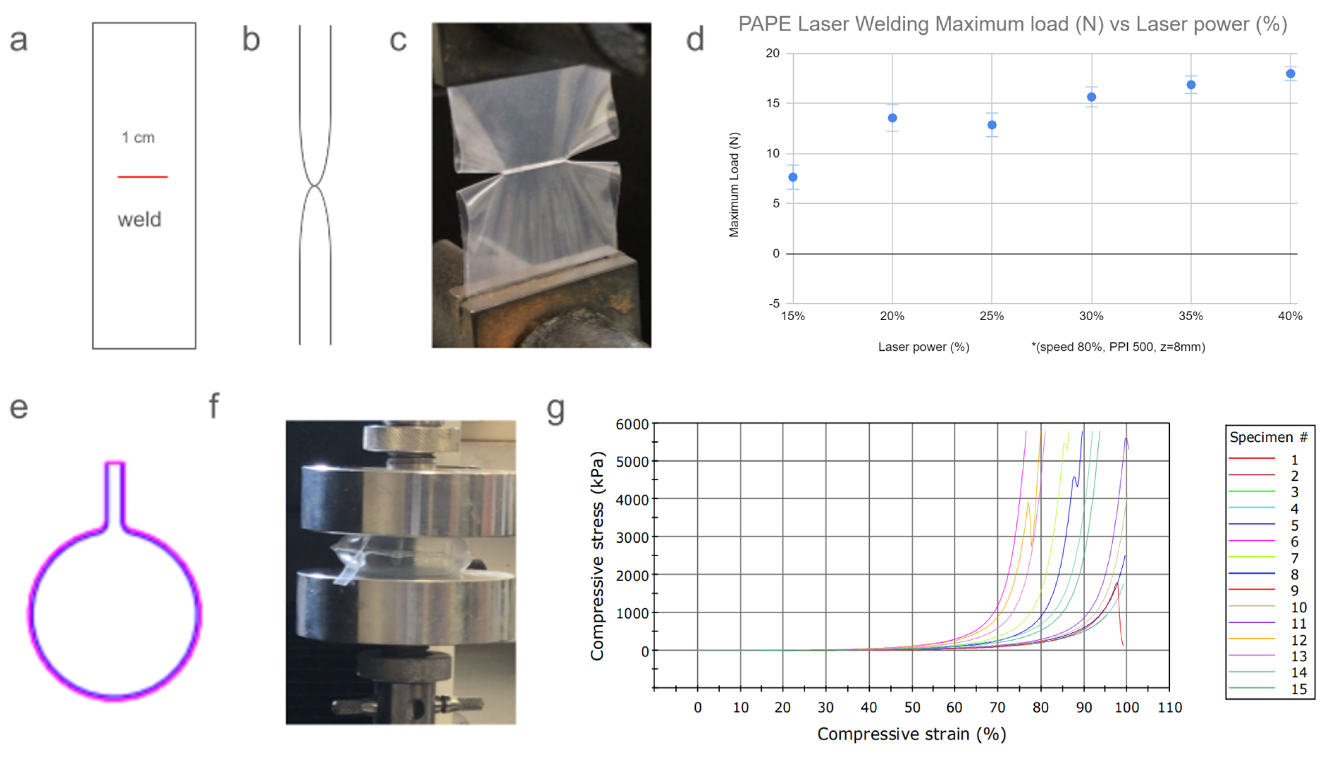
2.3. Laser Welding Validation Assay

We employed two types of assays to assess the effectiveness of the laser welding technique. Initially, a vector line was delineated at a width of 1 cm and subjected to welding using various laser settings. Subsequently, we tested the welds for each laser setting and examined them using an Instron machine (Instron 3345 tester, Norwood, MA, USA) to determine its tensile strength and maximum load capacity. In addition, we designed a circular shape with a diameter of 3 cm, featuring an inlet port for the introduction of air. These structures were then filled with air and subjected to compression assays using the Instron machine. Subsequent to the assays, the airbags were visually evaluated for integrity and performance.

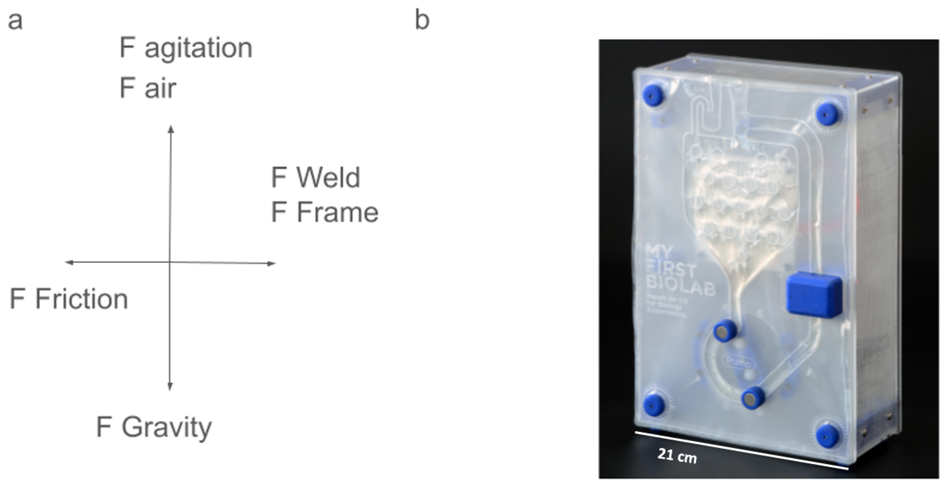
2.4. Design Principles

The design of laser-printed macrofluidic devices involves several key considerations to ensure optimal performance and functionality. Generally, any 3D vessel can be modeled in 2D and be fabricated into a 3D macrolfuidic device, for example, a peristaltic pump or a conical bottom vessel [34,35]. Within the confines of a macrofluidic device containing both liquids and gasses, several fundamental forces dictate the system’s behavior. Gravitational force orchestrates the distribution of mass, causing the liquid to settle at the device’s bottom while gas occupies the upper regions. Buoyant force emerges from density disparities, influencing the equilibrium by determining the position of the water–air interface. At this interface, surface tension exerts its influence, shaping the interface and contributing to system stability. Pressure differentials, arising from the coexistence of liquids and gasses, generate variations in pressure across depths and interfaces. When an actuator, such as a DC motor-based magnetic perstaltic pump, is integrated into the system (See Figure 1a,b), additional dynamics emerge. The actuator drives fluid flow through the device by directly manipulating the liquid and air phases within the channels, altering pressure gradients and flow velocities. In the case of Figure 1b and as described in [34], the size of film we used is 21 over 30 cm, the operating volume is 5–15 mL, and the pump works up to 1 mL/s.

2.4.1. Fluidic Channel Layout

The layout of fluidic channels determines the overall functionality and performance of the device. Designers must consider factors such as flow rate, mixing efficiency, and pressure drop when designing the channel geometry. Common layouts will be representations of already existing devices that are made from flexible tubes, glass or plastic reactors, and various types of pumps such as peristaltic, air, and piston. Maintaining a consistent distance between welding points is crucial for ensuring uniform distribution of forces across macrofluidic devices. This consistency enhances structural integrity by evenly distributing stresses between pegs and welds, while also ensuring a constant height for the fluidic channels. Uniform channel height guarantees a consistent shape throughout the device, essential for accommodating different actuators and optimizing liquid performance. By keeping channel height constant, a predictable and workable environment is created for device components and functionalities, enhancing reliability and functionality. For example in [34] and in Figure 1a, the design of the main chamber included circular welds, and this allowed for the distance between the sheets to be constant, which improved heat transmission to the liquids in the device.

2.4.2. Introduction of Gasses, Liquids, or Solids

In order to introduce gasses, liquids, or solids into the fluidic device, designated ports are designed according to the shape of the attachment, for example, the diameter of a flexible tube has a different shape than the design for a tube cap (See Figure 2a). These attachments are to be connected to the fluidic device under sterile conditions in order to ensure sterility. An air filter can be connected by introducing a sterilized tube and securing it with a zip tie (Figure 2a). A screw cap from a 15 mL tube can be connected by creating a fitting design and securing it with a ziptie (Figure 2b). Finally, larger solids such as scaffolds can be inserted in a laminar flow hood and welded with a plastic bag sealer (Figure 2c). When designing a port, it is important to consider that the distance between two welding points becomes smaller once the two sheets are opened (Figure 2d); after insertion of a flexible tube or tube cap, the zip tie holds firmly, and sterility and shape are maintained. The ports allow for the introduction of gasses, liquids, and solids into the MSUB (Macrofluidic single-use Bioreactor) before and during the experimentation process. A tube cap allows for the utilization of standard labware to introduce media, and a large port can allow for the introduction of a large scaffold and to seal the MSUB after insertion, thus maintaining sterility. Connecting a pump and an air filter to the flexible tube makes it possible to introduce gasses while maintaining sterility.

2.4.3. Integration of Sensors and Actuators

To enable real-time monitoring and control of fluidic processes, sensors and actuators can be integrated directly into and onto the fluidic circuit. These components may include temperature sensors, spectral sensors, force sensors, flow sensors, peristaltic pumps, piston pumps, air pumps, and valves, all of which can be controlled by a microcontroller, programmable and accessible by WiFi [34,35]. The integration of sensors and actuators allows for the precise regulation of fluid flow, temperature, and other environmental parameters. This may involve non-invasive sensors such as light and temperature monitoring through or in proximity to the device or sensors that receive an input that was in the device, such as a CO2 sensor monitoring gasses from the exhaust of the system.

2.4.4. Control and Monitoring

Control of the macrofluidic device is attained through a combination of established infrastructure and tailored solutions. We used a spectral sensor (AS7262 Visible Breakout, Sparkfun, Boulder, CO, USA) and an LED (5 mm orange LED) to measure optical density in 600 NM as an indicator for bacterial growth [34]. Mammalian cell cultures require temperature regulation and a 5% CO2 environment. We achieved this by housing the macrofluidic device in a CO2 incubator. For precise aeration control within the macrofluidic device, we employed an air pump linked to an esp-32 microcontroller, enabling programmable adjustments. This setup not only facilitated precise control over aeration but also enabled the IoT-based management of the air pump [35].

3. Results

3.1. Laser Welding Validation Assay

In our study, we conducted a calibration test to assess the effectiveness of laser welding in bonding PAPE bilayers. The design featured a 1 cm weld (Figure 3a–c) which underwent testing using an Instron testing machine. We observed that the weld demonstrated increased maximum as we increased the power of the laser; however, as we increased the power of the laser, the films’ structural integrity was compromised due to heat damage. We found that, at 20–30% power at 80% speed and Z = 8 mm (Figure 3d), the welds were sufficiently strong, and importantly, the PAPE bilayer remained intact despite the heat generated by the laser (see Supplementary Figure S2). This suggests that this specific power setting is optimal for achieving strong welds without causing thermal damage to the materials being bonded (see Supplementary Figure S2). In addition to evaluating laser welding, we also assessed the performance of PAPE to hold gasses under compression, and we designed a 3 cm airbag usingAdobe Illustrator, as seen in Figure 3e, filling them up with air and sealing them with a manual heat sealer. Then, we programmed the Instron machine to conduct maximum compression over the air bag in order to evaluate sealing (Figure 3f). Our findings reveal that similar airbags exhibit surprising resistance to compression. Even after undergoing maximum compression, some airbags maintained their original shape and did not break (Figure 3g), indicating their durability and ability to withstand significant pressure. The calibration performed in these tests measuring force under pressure and by stretching coupled with visual evaluation of deformations allowed us to have consistent results from the laser welding process.

3.2. Sterility

The production process of the film we used renders it sterile on the inside due to several key factors inherent to the manufacturing method. Firstly, during the production process, plastic pellets are heated and extruded in high pressure to form a thin tube, while the polyethylene and polyamide flakes undergo intense heating and stretching, which effectively kills any microorganisms present within the material. This high-temperature treatment, often exceeding sterilization thresholds, eliminates bacteria, viruses, and other contaminants that may have been introduced during handling or storage. As the extruded film tube is cooled, it is continuously wrapped into a roll. In this roll, the inside of the tube creates the area between the layers. As long as they are compressed tightly against each other, sterility between the sheets is maintained, which we evaluated by storing LB broth for prolonged periods of time without contamination [34,35]. proving it suitable for various applications where sterility is paramount. The introduction of ports, liquids, solids, and gasses (See Figure 2) has to be performed in a laminar flow hood with sterile or sterilized components.

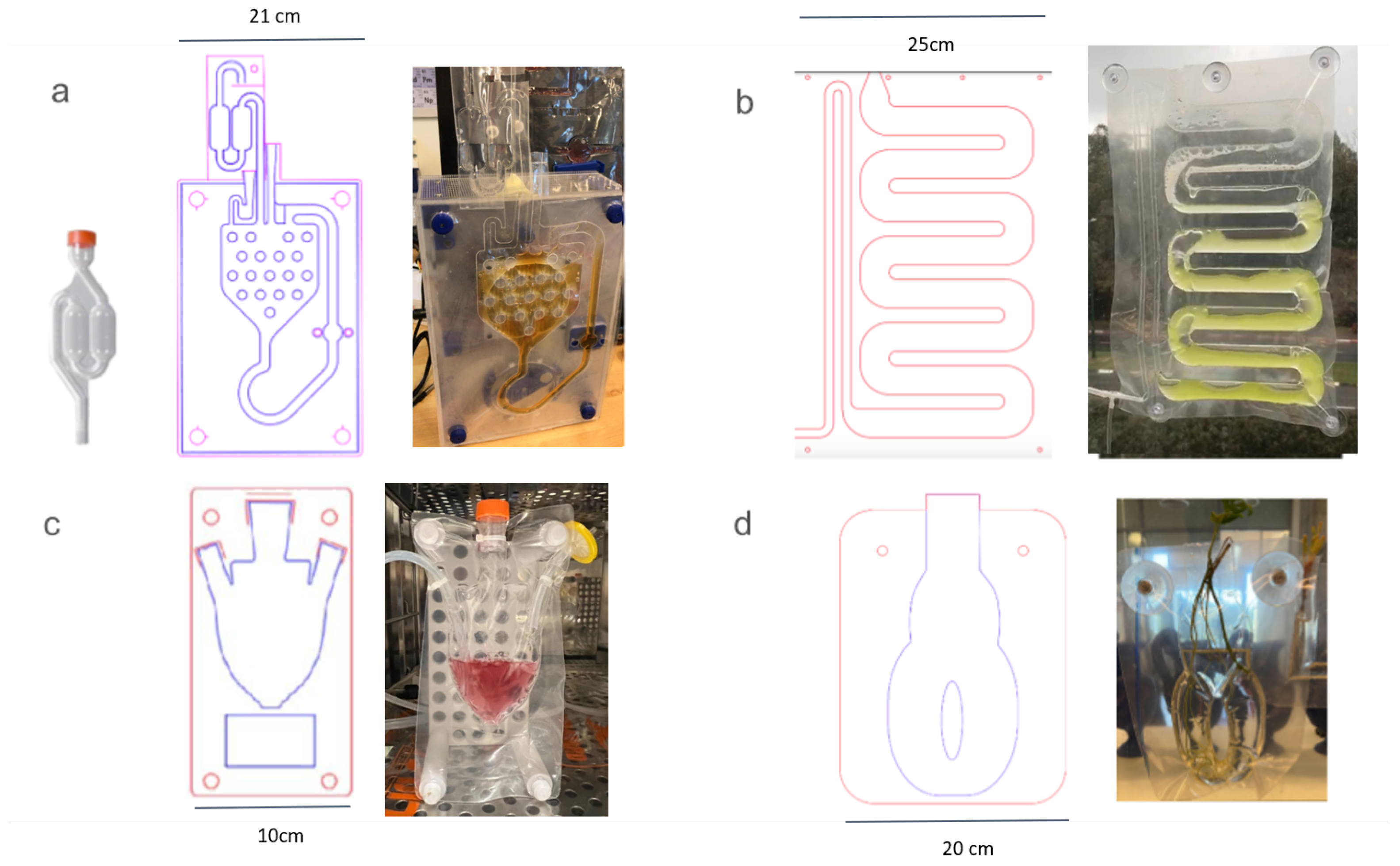
3.3. Designs for Cultivation of All Kingdoms of Life

The efficient fabrication method and inherent sterility allows for the fabrication of applications relating to all kingdoms of life. We illustrate examples that we evaluated and some that are in the works to demonstrate the versatility of this method.

3.4. Microorganisms in Suspension

As outlined in [34], the system enables the culture and monitoring of E. coli. The peristaltic pump actuates the liquids, resulting in a solution that is constantly monitored and maintained in a constant temperature. However, to culture yeast, the inclusion of an airlock valve is necessary to let gasses out while maintaining sterility. Therefore, we copied the design of a standard plastic airlock and included it in the fluidic design (Figure 4a), which showed how a function is carried out by a design that would otherwise require purchasing an additional component. Furthermore, the system facilitates the cultivation of microalgae, such as Chlorella spp., utilizing the air pump for aeration and agitation (Figure 4b).

3.5. Animal Cell Lines

The macrofluidic device for cultivating bovine stem cells on scaffolds provides a controlled environment for cell growth (Figure 4c). It features a cap for manual media replacement and liquid handling, ensuring optimal conditions for stem cell proliferation. This device is designed to accommodate small scaffold structures, facilitating cell adhesion and proliferation. It features controllable overhead aeration defined by user input via the wireless user interface. It is suitable for laboratory use, offering researchers a versatile tool for studying cell behavior and tissue engineering applications. The device is laser-printed and ports are added in sterile conditions in a laminar flow hood, as described in [35]. Once the ports are assembled, gasses can be introduced and removed constantly through the filters, and liquids can be added or removed in a laminar flow hood under sterile conditions.

3.6. Plants

The macrofluidic device for rooting epiphytes creates an ideal environment for root development; it takes inspiration from a standard vase. As seen in (Figure 4d), two holes are used for mounting on flat surfaces with two vacuum suction cups. Optionally, sensors on such a device can monitor conditions like temperature and humidity for optimal growth; in addition, they may allow for control over water, nutrients, and airflow. This compact design is convenient for home or laboratory use, promoting efficient rooting of epiphytes. This design offers solutions for research in root formation, the design of which can help researchers measure the length of roots over time under different conditions.

3.7. Design Mimicry for Existing Macrofluidic Infrastructure

Laser-printed macrofluidics can be designed based on existing devices; here, we demonstrate three common types of bioreactors and their representation in a 2D macrolfuidic design. The airlift bioreactor can be functional due to its already vertical position (Figure 5a). The introduction port for air is designed in a way that takes the air in above water level and introduces it at the bottom of the cylinder. A perfusion bioreactor with a media reservoir and a waste chamber can be modeled in 2D and work in a vertical system with peristaltic pumps (Figure 5b). This design of reservoir–pump–waste is constant throughout regenerative medicine research and would otherwise require using glassware, tubes, and peristaltic pumps. In this case, all of the fluid structure is printed in one go without connectors, reducing the risk of contamination. Finally, by designing two large connected chambers one over the other, and by applying force with a linear actuator on the entire surface area of the lower chamber, we can create a temporary submersion bioreactor wherein cultivation occurs in the upper chamber (Figure 5c).These bioreactors are useful for the cultivation of mammalian cell lines on macro carriers or for the rapid multiplication of plant cultures.

3.8. Design for Bioprocess—Media Replacement and Perfusion through a Scaffold

The design of this macrofluidic device encompasses a perfusion bioreactor system, featuring a dedicated port for scaffold introduction. Coupled with a peristaltic pump mechanism regulating media flow from the reservoir through the scaffold area to the waste chamber, this setup enables precise control over nutrient delivery and waste removal (Figure 5b).

4. STEM Education

Additionally, we used the MSUB in multiple educational settings. The affordability, rapid and easy prototyping and manufacture, in addition to the closed/self-contained nature of these systems make them a good fit for use with learners of all ages. Students can design new experiments or interact with an experiment that was already designed.

4.1. Algae Oxygen Monitoring

A student was interested in monitoring algae oxygen production and iterated designs to achieve their goal. The device needed to address the critical aspects of aeration for mixing and the supplementation of essential gasses such as oxygen and carbon dioxide to sustain microalgae growth. In essence, the student was tasked with creating a sophisticated system that could efficiently nurture microalgae while harnessing their metabolic byproduct—an endeavor that not only required technical expertise but also ingenuity and perseverance in problem solving (see Supplementary Figure S1a).

4.2. Inquiry-Based Learning for Bacterial Fermentation

As presented in [36], students were left to interact with an MSUB that allowed for the cultivation of e.coli and monitoring via IoT on an online interface the optical density of the liquid in the MSUB over the fermentation process. The students could chose the temperature, the speed, and the direction of the magnetic peristaltic pump. The students were studying by preforming a scientific process, while actively participating and self-exploring various aspects, critical hallmarks of inquiry-based learning.

4.3. Experiment in a Bag

We designed a hands-on chemistry experiment for elementary school children. We devised a macrofluidic circuit for a lava lamp experiment wherein students mixed colored water, oil, and baking soda. The macrofluidic device necessitated no sensors or actuators. The student manually mixed the liquids by pushing them with their fingers, instigating a chemical reaction which showed that oil is lighter than water and that gas is lighter than both. The materials utilized were readily available in any kitchen and comprised water, baking soda, oil, and Red Dye 40 (see Supplementary Figure S1b).

5. Discussion

In comparison to existing fabrication tools like 3D printing such as DLP, SLA, and CNC machines utilized for building fluidic systems, laser-printed macrofluidic devices offer distinct advantages and novel capabilities. While 3D printing and CNC machining excel in creating three-dimensional structures with intricate geometries, they often entail longer fabrication times and higher costs, particularly for complex fluidic designs [37,38]. Laser printing macrofluidics only takes minutes while 3D printing will probably require hours or days depending on size. In addition, 3D-printed fluidics will require to go through sterilization and biocompatibility and leak assessments before being used.
Single-use bioreactors are increasingly being used in the production of high-value products [39,40], which may be due to business aspects and not due to the actual cost of production of these systems, and have potential applications in regenerative medicine [22,40]. Providing scientists with the means to produce single-use systems themselves may allow for more experiments for a reduced overall cost, and therefore more iterations that may lead to better outcomes.
Leveraging laser printing technology in macrofluidic device fabrication introduces a transformative approach, converting two-dimensional designs into functional three-dimensional fluidic systems. This innovative process involves strategically welding thermoadhesive films to seamlessly integrate intricate fluidic channels, chambers, and ports into the device [35]. By transitioning from 2D to 3D, macrofluidic devices achieve complex fluidic architectures rapidly and affordably, circumventing the constraints of traditional fabrication methods. These laser-printed macrofluidic devices offer exceptional versatility and scalability, facilitating the rapid prototyping of fluidic circuits with integrated sensors and actuators. This agility in both design and fabrication empowers the creation of customized fluidic systems tailored to specific applications, while also providing precise control over fluid manipulation and environmental conditions [34,35].
When compared to traditional machining of large fluidic systems using stainless steel, rubber O rings, glass and plastic connectors and tubing, laser macrofluidics is more suitable for rapid prototyping as it is made from one material that is more affordable than all those mentioned above [41]. In addition, the speed of fabrication is faster than for modern fluidic fabrication methods such as 3D printing, taking minutes instead of hours or days while maintaining the sterility of the chamber throughout the fabrication process; in addition, 3D-printed fluidics may be difficult to make waterproof and not be as smooth as a an extruded polymer, as both may have an impact on the designed bioprocess [42].
Moreover, in terms of sterility, biocompatibility with microorganisms, plants and animal cells and tissues, and usability, laser-printed macrofluidic devices can outperform their traditional counterparts. The blow film employed in their fabrication inherently upholds sterility, minimizing the risks of contamination and simplifying experimental setups [34,35]. They are unlike conventional fluidic systems where an autoclave is used when possible and sterilized with either gamma rays or ethanol and washing with a buffer when the parts are heat-sensitive [41,43], thereby enhancing operational efficiency and reducing downtime [21]. In all single-use bioreactors, the seals and motor coupling are critical for maintaining sterility [20]. Magnetic driving answers sterility demands in traditional systems while in MSUB this is achieved without coupling into an element in the bioreactor but rather by actively agitating the liquids by moving magnets through the film on a channel outside of the vessel. Figure 1b shows the macrofluidic design for a peristaltic pump [44].
The incorporation of manually sealable ports or those secured by zip ties maintains sterility while facilitating the introduction of liquids, solids, and gasses into chambers within the macrofluidic device without compromising sterility. This can be achieved either by working with sterilized elements in a biological hood or by introduction through a filter. Designing for existing infrastructure can involve directly translating the 3D fluidics of the existing device into a 2D representation, considering volumes and functionality, and maintaining a relatively constant or low distance between welding points. Alternatively, physical limitations over the film can be fabricated by pressing the fluid between the backboard and another board on the opposite side.
Laser-printed macrofluidics are heat-conducive, clear and flexible, allowing for sensors such as a thermometer, microscope, or a light sensor to measure temperature, optical density, or take images. Actuators such as the magnetic peristaltic pump we presented in previous works [34] can actuate the liquids without compromising sterility and connecting an off-the-shelf peristaltic pump, reducing chances of contamination.
Additionally, designs for functionality do not need to precisely replicate the 3D design of the existing device. Other designs may prove as or more effective; for example, a temporary submersion bioreactor could be horizontal rather than vertical and utilize a peristaltic pump instead of a piston (Figure 5c). In order to predict fluidics outcome in silico, Computational fluid dynamics (CFD) can potentially allow for furthering optimization of laser-printed macrofluidics.
While 3D printing and CNC machining remain indispensable for certain applications requiring intricate three-dimensional structures, laser-printed macrofluidic devices emerge as a compelling alternative for rapid prototyping of fluidic systems. Their ability to seamlessly translate 2D designs into functional 3D fluidic architectures, coupled with advantages in cost-effectiveness, sterility, and scalability, positions them as a potentially transformative tool in scientific research, biomedical engineering, and industrial applications.

6. Conclusions

Laser-printing macrofluidics offers a versatile and scalable approach for fabricating large fluidic circuits with integrated sensors and actuators. We present design guidelines for creating custom macrofluidic devices tailored to specific applications. Our study demonstrated the efficacy of high-resolution laser printing for rapid prototyping of macrofluidics on a polymer bi-layer, and the designs can allow for control over fluid and gas. The optimized fabrication process ensures that the devices are free from sterility and leakage issues. We optimize the fabrication process by testing the welds by stretching and compressing them in a testing machine. The laser-printed macrofluidic devices proved versatile in biological applications, successfully accommodating various cell types, including algal, yeast, and mammalian cells, as well as whole plants. The integration of sensors and actuators enhanced their functionality, allowing for real-time monitoring and control. The devices exhibited high mechanical robustness, maintaining integrity and functionality under dynamic conditions, crucial for practical applications. Additionally, laser printing is significantly faster than traditional 3D printing, further enhancing its suitability for rapid prototyping and iterative design processes. The ability to incorporate ports for liquids and gasses while maintaining sterility expands the operational capabilities of these devices. The scalable and cost-effective nature of the laser-printing approach makes it accessible for widespread use. Improved fluid and gas manipulation within the devices opens new possibilities for complex experimental setups, enhancing precision and reliability in biological experiments. These findings highlight the potential of laser-printed macrofluidics to support research and innovation in fluidic systems, offering powerful tools for advancing biomedical research, synthetic biology, tissue engineering, and STEM education by enabling precise manipulation and maintenance of diverse systems.

7. Patents

WO2020105044-BIOLOGICAL FLUIDIC SYSTEM.

Supplementary Materials

The following supporting information can be downloaded at: https://www.mdpi.com/article/10.3390/inventions9040068/s1, Figure S1: Stem Education; Figure S2: Laser welding microscopy.

Author Contributions

Conceptualization, G.G.; methodology, G.G.; validation, G.G.; formal analysis, G.G.; resources J.G., G.G. and O.S.; writing—original draft preparation, G.G.; writing—review and editing, J.G., O.B. and O.S.; visualization, G.G.; supervision, O.B. and O.S.; All authors have read and agreed to the published version of the manuscript.

Funding

This research was funded by the Israeli Ministry of Innovation, Science and Technology, Levi Eshkol Scholarship, grant number 3031000233 and partially supported by the Israeli Innovation Authority through the cultivated meat consortium (file number 82446).

Data Availability Statement

The original contributions presented in the study are included in the article/supplementary material, further inquiries can be directed to the corresponding authors.

Acknowledgments

Laser welding of macrofluidics is supported by and sprouted at the media innovation lab (milab) at Reichman University led by Oren Zuckerman, Andrey Grishko, Iddo wald and Omer Kaplan who preformed the algae experiments. The authors would like to acknowledge Guy Aidelberg from CRI Paris for fruitful discussions.

Conflicts of Interest

The authors declare no conflicts of interest. The funders had no role in the design of the study; in the collection, analyses, or interpretation of data; in the writing of the manuscript; or in the decision to publish the results.

Abbreviations

The following abbreviations are used in this manuscript:
PAPEPolyethylene–Polyamide
MSUBMacrofluidic Single-Use Bioreactor

References

  1. Gale, B.K.; Jafek, A.R.; Lambert, C.J.; Goenner, B.L.; Moghimifam, H.; Nze, U.C.; Kamarapu, S.K. A review of current methods in microfluidic device fabrication and future commercialization prospects. Inventions 2018, 3, 60. [Google Scholar] [CrossRef]
  2. Raj, M.K.; Chakraborty, S. PDMS microfluidics: A mini review. J. Appl. Polym. Sci. 2020, 137, 48958. [Google Scholar] [CrossRef]
  3. Mohan, J.M.; Amreen, K.; Javed, A.; Dubey, S.K.; Goel, S. Emerging trends in miniaturized and microfluidic electrochemical sensing platforms. Curr. Opin. Electrochem. 2022, 33, 100930. [Google Scholar] [CrossRef]
  4. Zaman, M.A.; Padhy, P.; Wu, M.; Ren, W.; Jensen, M.A.; Davis, R.W.; Hesselink, L. Controlled Transport of Individual Microparticles Using Dielectrophoresis. Langmuir 2023, 39, 101–110. [Google Scholar] [CrossRef] [PubMed]
  5. Sivaramakrishnan, M.; Kothandan, R.; Govindarajan, D.K.; Meganathan, Y.; Kandaswamy, K. Active microfluidic systems for cell sorting and separation. Curr. Opin. Biomed. Eng. 2020, 13, 60–68. [Google Scholar] [CrossRef]
  6. Truskey, G.A.; Fu, J. The future of Biomedical Engineering: Bioengineering of Organoids and Tissue Development. Curr. Opin. Biomed. Eng. 2020, 13, A1–A2. [Google Scholar] [CrossRef]
  7. Li, J. Current commercialization status of electrowetting-on-dielectric (EWOD) digital microfluidics. Lab Chip 2020, 20, 1705–1712. [Google Scholar] [CrossRef] [PubMed]
  8. Goller, C. Library Preparation 1–Miro and VolTRAX; Portable Genome Sequencing; Automation for Library Prep: San Diego, CA, USA, 2024. [Google Scholar]
  9. Matos, R.S.; Maselli, D.; McVey, J.H.; Heiss, C.; Campagnolo, P. 3D printed bioreactor enabling the pulsatile culture of native and angioplastied large arteries. Front. Cardiovasc. Med. 2022, 9, 864580. [Google Scholar] [CrossRef] [PubMed]
  10. Priyadarshini, B.M.; Dikshit, V.; Zhang, Y. 3D-printed bioreactors for in vitro modeling and analysis. Int. J. Bioprint. 2020, 6, 267. [Google Scholar] [CrossRef]
  11. Hoyle, H.; Smith, L.; Williams, R.; Przyborski, S. Applications of novel bioreactor technology to enhance the viability and function of cultured cells and tissues. Interface Focus 2020, 10, 20190090. [Google Scholar] [CrossRef]
  12. Saunders, S.K.; Cole, S.Y.; Acuna Sierra, V.; Bracamonte, J.H.; Toldo, S.; Soares, J.S. Evaluation of perfusion-driven cell seeding of small diameter engineered tissue vascular grafts with a custom-designed seed-and-culture bioreactor. PLoS ONE 2022, 17, e0269499. [Google Scholar] [CrossRef] [PubMed]
  13. Smith, A.F.; Thanarak, J.; Pontin, M.; Green, N.H.; Damian, D.D. Design and development of a robotic bioreactor for in vitro tissue engineering. In Proceedings of the 2021 IEEE International Conference on Robotics and Automation (ICRA), Xi’an, China, 30 May–5 June 2021; IEEE: Piscataway, NJ, USA, 2021; pp. 12428–12434. [Google Scholar]
  14. Hoyle, H.; Stenger, C.; Przyborski, S. Design considerations of benchtop fluid flow bioreactors for bio-engineered tissue equivalents in vitro. Biomater. Biosyst. 2022, 8, 100063. [Google Scholar] [CrossRef] [PubMed]
  15. Schmid, A.; Kreidl, E.; Bertschinger, M.; Vetsch, P. Benchtop bioreactors in mammalian cell culture: Overview and guidelines. In Bioreactors in Stem Cell Biology: Methods and Protocols; Springer: Berlin/Heidelberg, Germany, 2021; pp. 1–15. [Google Scholar]
  16. Reina-Mahecha, A.; Beers, M.J.; van der Veen, H.C.; Zuhorn, I.S.; van Kooten, T.G.; Sharma, P.K. A Review of the Role of Bioreactors for iPSCs-Based Tissue-Engineered Articular Cartilage. Tissue Eng. Regen. Med. 2023, 20, 1041–1052. [Google Scholar] [CrossRef] [PubMed]
  17. Todros, S.; Spadoni, S.; Maghin, E.; Piccoli, M.; Pavan, P.G. A novel bioreactor for the mechanical stimulation of clinically relevant scaffolds for muscle tissue engineering purposes. Processes 2021, 9, 474. [Google Scholar] [CrossRef]
  18. Bender, R.J.; Askinas, C.; Vernice, N.A.; Dong, X.; Harris, J.; Shih, S.; Spector, J.A. Perfuse and Reuse: A Low-Cost Three-Dimensional-Printed Perfusion Bioreactor for Tissue Engineering. Tissue Eng. Part C Methods 2022, 28, 623–633. [Google Scholar] [CrossRef] [PubMed]
  19. Pai, A.C.; Lynch, T.J.; Ahlers, B.A.; Ievlev, V.; Engelhardt, J.F.; Parekh, K.R. A novel bioreactor for reconstitution of the epithelium and submucosal glands in decellularized ferret tracheas. Cells 2022, 11, 1027. [Google Scholar] [CrossRef] [PubMed]
  20. Schirmer, C.; Maschke, R.W.; Pörtner, R.; Eibl, D. An overview of drive systems and sealing types in stirred bioreactors used in biotechnological processes. Appl. Microbiol. Biotechnol. 2021, 105, 2225–2242. [Google Scholar] [CrossRef] [PubMed]
  21. Sharma, R.; Harrison, S.T.; Tai, S.L. Advances in bioreactor systems for the production of biologicals in mammalian cells. ChemBioEng Rev. 2022, 9, 42–62. [Google Scholar] [CrossRef]
  22. Nogueira, D.E.; Cabral, J.M.; Rodrigues, C.A. Single-use bioreactors for human pluripotent and adult stem cells: Towards regenerative medicine applications. Bioengineering 2021, 8, 68. [Google Scholar] [CrossRef]
  23. Nikita, S.; Mishra, S.; Gupta, K.; Runkana, V.; Gomes, J.; Rathore, A.S. Advances in bioreactor control for production of biotherapeutic products. Biotechnol. Bioeng. 2023, 120, 1189–1214. [Google Scholar] [CrossRef]
  24. Nielsen, M.; Meyer, A.; Arnau, J. The Next Food Revolution Is Here: Recombinant Microbial Production of Milk and Egg Proteins by Precision Fermentation. Annu. Rev. Food Sci. Technol. 2023, 15. [Google Scholar] [CrossRef] [PubMed]
  25. Maguire, D.; Coughlan, N.E.; Jansen, M.A.; Byrne, E.P.; Kavousi, F. Where engineering meets biology: The Computational Fluid Dynamic analysis of a stacked duckweed bioreactor. Aquac. Eng. 2024, 104, 102375. [Google Scholar] [CrossRef]
  26. Garcia-Aponte, O.F.; Herwig, C.; Kozma, B. Lymphocyte expansion in bioreactors: Upgrading adoptive cell therapy. J. Biol. Eng. 2021, 15, 13. [Google Scholar] [CrossRef] [PubMed]
  27. Uma, S.; Karthic, R.; Kalpana, S.; Backiyarani, S.; Saraswathi, M.S. A novel temporary immersion bioreactor system for large scale multiplication of banana (Rasthali AAB—Silk). Sci. Rep. 2021, 11, 20371. [Google Scholar] [CrossRef] [PubMed]
  28. Ravindran, S. How DIY technologies are democratizing science. Nature 2020, 587, 509–512. [Google Scholar] [CrossRef] [PubMed]
  29. Aidelberg, G.; Aronoff, R.; Eliseeva, T.; Quero, F.J.; Vielfaure, H.; Codyre, M.; Hadasch, K.; Lindner, A.B. Corona Detective: A simple, scalable, and robust SARS-CoV-2 detection method based on reverse transcription loop-mediated isothermal amplification. J. Biomol. Tech. JBT 2021, 32, 89. [Google Scholar] [CrossRef] [PubMed]
  30. Cerda Rojas, A.; Aravena, A.; Arce, A.; Zapata, V.; Araya, W.; Gallardo, D.; Aviles, J.; Quero, F.; Nunez, I.; Matute, T.; et al. Open Educational Resources for distributed hands-on teaching in molecular biology. bioRxiv 2024. [Google Scholar] [CrossRef]
  31. Wenzel, T. Open hardware: From DIY trend to global transformation in access to laboratory equipment. PLoS Biol. 2023, 21, e3001931. [Google Scholar] [CrossRef] [PubMed]
  32. Cohen, N.; Sicher, E.; Ayala-Garcia, C.; Sanchez-Fayos, I.M.; Conterno, L.; Ugur Yavuz, S. Innocell Bioreactor: An Open-Source Development to Produce Biomaterials for Food and Packaging Based on Fermentation Processes. Fermentation 2023, 9, 915. [Google Scholar] [CrossRef]
  33. Cohen, N.; Sicher, E.; Merino, I.; Yavuz, S.U. An Open-Source Bioreactor Enhancing Microbial Cellulose Production and Novel Sustainable substances. In Sustainable Design and Manufacturing, Proceedings of the 8th International Conference on Sustainable Design and Manufacturing (KES-SDM 2021), Split, Croatia, 15–17 September 2022; Springer: Berlin/Heidelberg, Germany, 2022; pp. 77–86. [Google Scholar]
  34. Gome, G.; Fein, Y.; Waksberg, J.; Maayan, Y.; Grishko, A.; Wald, I.Y.; Zuckerman, O. My First Biolab: A System for Hands-On Biology Experiments. In Proceedings of the Extended Abstracts of the 2019 CHI Conference on Human Factors in Computing Systems, Glasgow, UK, 4–9 May 2019; pp. 1–6. [Google Scholar]
  35. Gome, G.; Chak, B.; Tawil, S.; Shpatz, D.; Giron, J.; Brajzblat, I.; Weizman, C.; Grishko, A.; Schlesinger, S.; Shoseyov, O. Cultivation of Bovine Mesenchymal Stem Cells on Plant-Based Scaffolds in a Macrofluidic Single-Use Bioreactor for Cultured Meat. Foods 2024, 13, 1361. [Google Scholar] [CrossRef]
  36. Fein, Y.; Gome, G.; Zuckerman, O.; Erel, H. My first biolab: An inquiry-based learning system for microbiology exploration. In Proceedings of the 2020 ACM Interaction Design and Children Conference: Extended Abstracts, London, UK, 17–24 June 2020; pp. 292–295. [Google Scholar]
  37. Scott, S.M.; Ali, Z. Fabrication methods for microfluidic devices: An overview. Micromachines 2021, 12, 319. [Google Scholar] [CrossRef] [PubMed]
  38. Pörtner, R.; Giese, C. An overview on bioreactor design, prototyping and process control for reproducible three-dimensional tissue culture. In Drug Testing In Vitro: Breakthroughs and Trends in Cell Culture Technology; Wiley: Hoboken, NJ, USA, 2007; pp. 53–78. [Google Scholar]
  39. Haigh, J.; Schmidt, S.; Vicalvi, J.; Winterhalter, C. 17th Annual Report and Survey on Biopharmaceutical Manufacturing Capacity and Production; BioPlan Associates, Inc.: Rockville, MD, USA, 2020. [Google Scholar]
  40. Mahal, H.; Branton, H.; Farid, S.S. End-to-end continuous bioprocessing: Impact on facility design, cost of goods, and cost of development for monoclonal antibodies. Biotechnol. Bioeng. 2021, 118, 3468–3485. [Google Scholar] [CrossRef] [PubMed]
  41. Zohar, B.; Blinder, Y.; Epshtein, M.; Szklanny, A.A.; Kaplan, B.; Korin, N.; Mooney, D.J.; Levenberg, S. Multi-flow channel bioreactor enables real-time monitoring of cellular dynamics in 3D engineered tissue. Commun. Biol. 2019, 2, 158. [Google Scholar] [CrossRef] [PubMed]
  42. Gabetti, S.; Masante, B.; Cochis, A.; Putame, G.; Sanginario, A.; Armando, I.; Fiume, E.; Scalia, A.C.; Daou, F.; Baino, F.; et al. An automated 3D-printed perfusion bioreactor combinable with pulsed electromagnetic field stimulators for bone tissue investigations. Sci. Rep. 2022, 12, 13859. [Google Scholar] [CrossRef] [PubMed]
  43. Oosterhuis, N.M.; Junne, S. Design, Applications, and Development of Single-Use Bioreactors. In Bioreactors; John Wiley Sons, Ltd.: Hoboken, NJ, USA, 2016; Chapter 9; pp. 261–294. [Google Scholar] [CrossRef]
  44. Milab. My First Biolab Video. YouTube Video. 2019. Available online: https://www.youtube.com/watch?v=1hQybiffh2Y (accessed on 4 April 2024).
Figure 1. Design principles for macrofluidic devices. (a) A scheme describing the forces in the macrolfuidic device. Gasses go up, liquids are forced down by gravity, and the fluidic device provides a horizontal force both by holding the welded film by pegs and by the welds on the PAPE itself. (b) Image for Macrofluidic device for the cultivation of E. coli [34].
Inventions 09 00068 g001
Figure 2. Design and implementation of ports. Designs were created using Adobe Illustrator, where blue indicates welding areas and red indicates cutting areas. (a) Gas-filtered input/output port. (b) Liquid port for manual liquid handling, utilizing a modified 15 mL tube cap secured with a zip tie. (c) Large solid integration port, demonstrated by the introduction of a 10 × 10 cm sponge, sealed thereafter with a manual bag sealer. (d) Schematic representation of port dimensions and design considerations, where D 1 represents the distance between two points, D 2 represents the distance after the 2 sheets are separated, and h represents the height created by the separation of the sheets.
Inventions 09 00068 g002
Figure 3. Calibration test for laser welding of PAPE bilayer using an Instron testing machine. (a) Design for a 1 cm weld. (b) Side view illustration of the 1 cm weld as it is tested in the Instron testing machine. (c) Image of the 1 cm weld as it is stretched until failure by the Instron testing machine. (d) A chart describing the maximum load at failure. (e) Design for an airbag. (f) The airbag is tested for maximum load by the Instron testing machine. (g) Strain vs stress on different airbags with the same design each color represents one experiment on one airbag.
Inventions 09 00068 g003
Figure 4. Different organisms require different designs. (a) Airlock valve design and implementation for cultivation of Saccharomyces cerevisiae (purple: weld, red: Cut). (b) Design for cultivation of micro algae with constant aeration (red: weld). (c) Design for mammalian cell culture with programmable gas exchange (blue: weld, red: cut). (d) Design for whole plant, epiphyte root propagation (blue: weld, red: cut).
Inventions 09 00068 g004
Figure 5. Designs for existing infrastructure. (a) Airlift bioreactor. (b) Perfusion bioreactor. (c) Temporary submersion bioreactor.
Inventions 09 00068 g005
Disclaimer/Publisher’s Note: The statements, opinions and data contained in all publications are solely those of the individual author(s) and contributor(s) and not of MDPI and/or the editor(s). MDPI and/or the editor(s) disclaim responsibility for any injury to people or property resulting from any ideas, methods, instructions or products referred to in the content.

