Review

Review on Research Progress of Pulsating Heat Pipes

1
School of Petroleum and Natural Gas Engineering, Changzhou University, Changzhou 213164, China
2
School of Energy, School of Petroleum and Natural Gas Engineering, Changzhou University, Changzhou 213164, China
3
School of Petrochemical Engineering, Changzhou University, Changzhou 213164, China
*
Authors to whom correspondence should be addressed.
Inventions 2024, 9(4), 86; https://doi.org/10.3390/inventions9040086
Submission received: 30 April 2024 / Revised: 4 June 2024 / Accepted: 7 June 2024 / Published: 30 July 2024
(This article belongs to the Special Issue Innovations in Heat Exchangers)

Abstract

:
Since their invention by Akachi in 1990s, pulsating heat pipes (PHPs) have attracted widespread interest and application in practice, e.g., grinding, chip cooling, the thermal management of batteries, etc., owing to their notable efficiency in heat transfer and their simplicity and flexibility in structure. Key factors influencing the heat transfer efficacy of pulsating heat pipes are mainly attributed to the thermophysical properties of the working fluid, the structural parameters, and the operating conditions. Research on pulsating heat pipes is conducted through theoretical investigations, numerical simulations, and visual experiments. In this paper, the research on PHPs in recent decades is reviewed with the consideration of the heat transfer performance mechanism and application of pulsating heat pipes, especially research under operation conditions such as with “status with motion” and with “inconsistent heat flux”.

1. Introduction

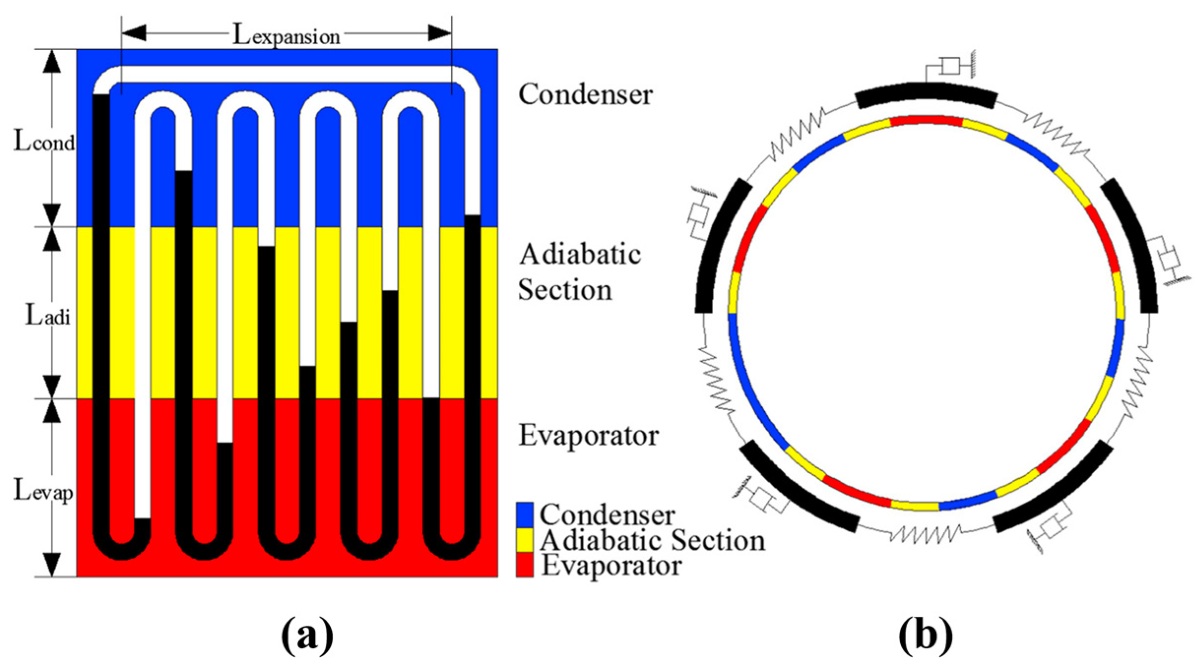
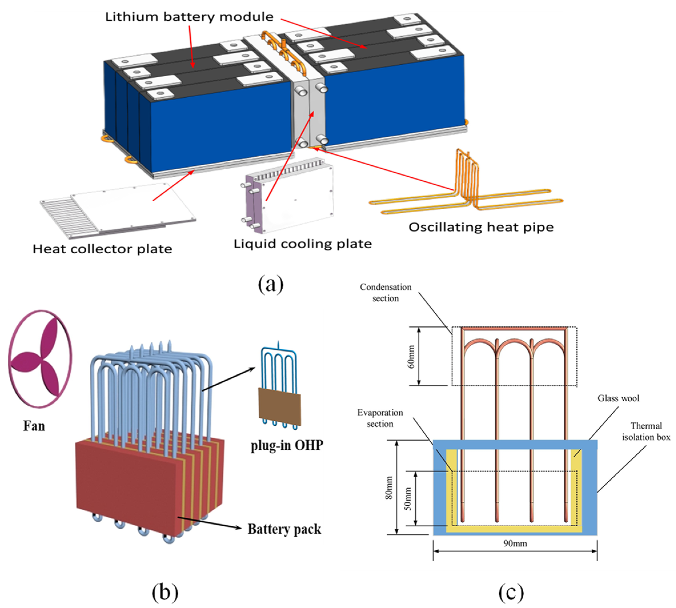
Pulsating heat pipes (PHPs), also referred to as oscillating heat pipes (OHPs) in certain references, represent an innovative heat transfer technology introduced by Akachi from Japan in the 1990s. A pulsating heat pipe consists of three main sections: an evaporator/heating section, a condenser/cooling section, and an adiabatic section [1,2,3,4], as shown in Figure 1. These pipes show a pulsating or oscillating movement of the working fluid within their channels, marking a significant advancement over traditional heat pipes and offering enhanced heat transfer capabilities in specific applications. Additionally, PHPs offer advantages such as high flexibility, rapid thermal response, and excellent heat transfer performance. Therefore, compared to traditional heat pipes, PHPs have a simpler and more compact structure, and are particularly suitable for applications where space is limited or there are cooling load challenges. Pulsating heat pipes find applications in various fields, including rotating machinery cooling [5], battery thermal management systems [6], the cooling of electronics [7], and aerospace [8]. It is noteworthy that pulsating heat pipes exhibit considerable heat transfer efficiency even under microgravity and hypergravity conditions [9].
Pulsating heat pipes consist of one or multiple closed- or open-loop channels, partially filled with a working fluid, i.e., a low-boiling-point liquid such as water or ethanol. That is to say, the working fluid in pulsating heat pipes exhibits a random distribution of liquid and vapor phases and no distinguished channels for liquid or vapor, in contrast to loop heat pipes (LHPs) [10], separate heat pipes (SHPs) [11], and gravity heat pipes (GHPs) [12,13], as shown in Figure 2. The working fluid experiences a phase change from liquid to vapor and back again as it absorbs and releases heat, respectively. The operation of the pulsating heat pipes entails the cyclical movement of the working fluid.
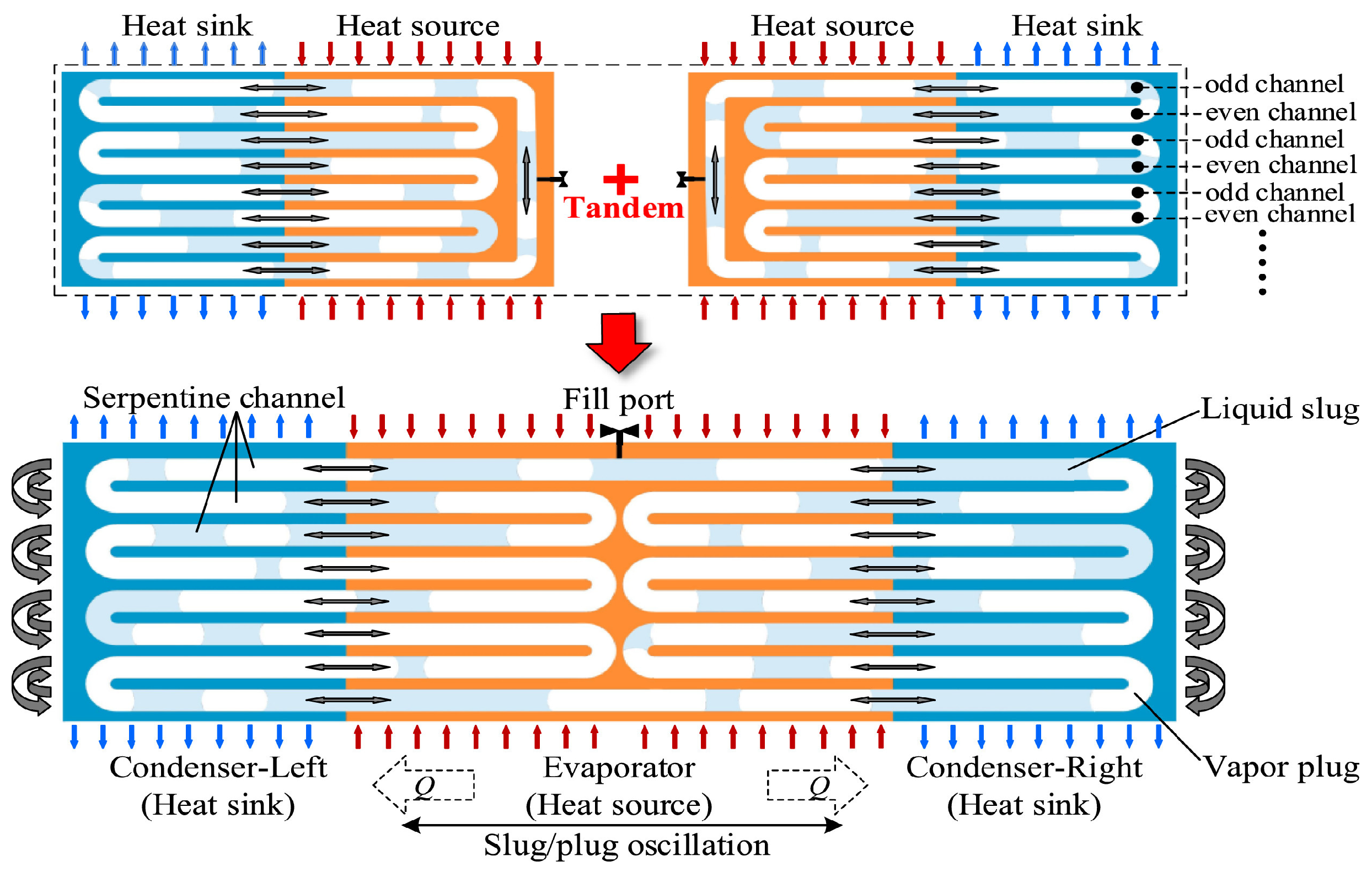
During operation, heat input at the evaporator sections causes the working fluid to vaporize and form vapor plugs or bubbles. Subsequently, the vapor plugs or bubbles travel along the channel due to pressure difference, reach the condenser section to release heat and condense, and return to the evaporator in the liquid phase through capillary action, gravity, or differential pressure. Because the gas–liquid flow direction in PHPs is random, pulsating motion forms within the channels, continuously scouring the inner walls of the channels, thus achieving continuous and efficient heat transfer. This pulsating motion helps overcome the limitations of traditional heat pipes, including gravitational constraints and large heat dissipation restrictions. Furthermore, the pulsating motion promotes the mixing and agitation of the working fluid, thereby enhancing the heat transfer rate and facilitating the efficient cooling of heat sources.
At present, the review of PHPs is mainly from the aspects of fluid selection, structure influence, operation conditions, mechanism study, and the visualization of pulsating heat pipes in a status without motion [14,15,16]. Han et al. [14] reviewed the research development of PHPs between 1999 and 2014, including geometric parameters, working fluids, operating parameters, operating mechanisms, and new application domains. Bastakoti et al. [15] reviewed the research of PHPs from the perspective of the design of their structure, operating parameters, working mechanisms, and theoretical and numerical modeling. And this review paper mainly focused on the results of experimental and numerical works carried out between 2009 and 2015. Xu et al. [16] summarized the research results of PHPs from the perspective of working fluids, operation mechanisms, and applications between 2001 and 2021. This review highlights the latest research progress in the field of nanofluids and recent advances in the application of nanofluids in PHPs. However, with the advancement of technology, the research on PHP varies from status without motion to status with motion, such as applications in grinding and microgravity conditions, and from continuous heating mode to inconsistent heating mode, such as periodic pulsating heat flux and auxiliary heat flux for BTM (battery thermal management). Therefore, there is a need for an up-to-date summary of conclusions made in recent years.
In this paper, a comprehensive review on the research progress of PHPs in recent decades is conducted, covering the scope of heat transfer performance and mechanisms, based on experimental, theoretical, and numerical analysis. In Section 2, the heat transfer performance of PHPs is summarized with the influence of the working fluid, structure parameters, and operation conditions, especially in status with motion and operation with inconsistent heat flux. Section 3 includes the mechanism of PHPs, with the consideration of theoretical models, numerical simulation, and optical visualization, especially the categories of theoretical models. In the last section, the application of PHPs is introduced.

2. Heat Transfer Performance of PHPs

The heat transfer performance of PHPs refers to the thermal resistance, heat transfer efficiency, starting speed, resistance to drying, etc. It is mainly influenced by the working fluid, structure parameters, and operating conditions.

2.1. Working Fluid

The working fluid is an important choice affecting the heat transfer performance of pulsating heat pipes, and different fluids are suitable for different operating conditions due to the variation in thermophysical parameters. Therefore, it is necessary to study the characteristics of different working fluids to help select suitable working fluids according to different operating conditions. In this section, working fluid is divided into single working fluids, composite working fluids, and mixed working fluids.

2.1.1. Single Working Fluids

The single working fluids commonly used in pulsating heat pipes are water [17,18,19,20,21,22], methanol [17,20,23,24], ethanol [25,26,27,28,29,30,31,32,33], and so on. Table 1 presents the single working fluids in PHPs as well as the effects of the properties of working fluids in cited references. Han et al. [24] investigated the heat transfer performance of closed-loop pulsating heat pipes with four different working fluids (deionized water, ethanol, methanol, and acetone) under different filling ratios and input heat flux. The results showed that PHPs filled with acetone are the easiest to start, while methanol is the most difficult. This is because acetone has the lowest dynamic viscosity, which results in smaller shear forces and correspondingly smaller flow resistances. In this study, dynamic viscosity is considered superior to all other thermal properties, becoming the dominant property for closed-loop PHP oscillation to start up. Hao et al. [34] investigated the heat transfer performance of polytetrafluoroethylene pulsating heat pipes (PHPs) with water, ethanol, and acetone as working fluids. The PHPs were tested in a vertically oriented heating setup. The study indicated that PHPs filled with acetone exhibit the best thermal performance compared to the other two working fluids. This is because acetone has the highest vapor pressure and lowest viscosity, resulting in a high driven force and low shear stress. And pulsating heat pipes with acetone are easier to start up. In addition, acetone has a higher resistance to drying at a low liquid filling ratio because of its lower contact angle on the surface. Bastakoti et al. [35] studied the heat transfer performance of pulsating heat pipes with different filling ratios of methanol, ethanol, and cetyltrimethyl ammonium chloride, C19H42ClN (CTAC), and compared them with that of deionized (DI) water. The results showed that methanol and ethanol have faster start-up speeds due to lower viscosity at 50% filling ratios, but CTAC has lower thermal resistance because of its lower surface tension.
In recent years, in order to explore the applications of PHPs in the low-temperature domain, an increasing number of scholars have turned their attention to studying the heat transfer performance of low-temperature working fluids, such as hydrogen [36,37,38,39], helium [40,41,42,43,44,45,46], and nitrogen [47,48,49,50,51,52,53]. To understand the heat transfer performance of hydrogen PHPs under different heating modes, Li et al. [39] investigated the heat transfer performance of PHPs under two heating modes (stepwise heating and sudden heating). The results indicated that the sudden heating mode leads to a more stable start-up of hydrogen PHPs due to its instantaneous high thermal load, especially under conditions of lower filling ratio when there is a more uneven distribution of liquid and vapor. This feature is advantageous for the future application of PHPs in heat dissipation for superconducting magnets. Bruce et al. [53] studied the thermal performance of a meter-scale horizontal nitrogen pulsating heat pipe. The study indicated that the maximum equivalent thermal conductivity measured is 85 kW/m·K. It can transfer a maximum heat power of 25 W before reaching its operation limit. Yi et al. [54] investigated the effects of heating power and filling ratios on the oscillation conditions and effective thermal conductivity (ETC) of helium PHPs. The results showed that with the increase in heating power, the ETC of helium-based PHPs first increases and then decreases, and has a maximum value. Moreover, with the increase in the initial liquid filling ratio, the dry-out power increases first and then decreases.
In general, working fluids with low boiling points, low dynamic viscosity, and low surface tension (such as acetone, methanol, and certain refrigerants) have lower start-up power requirements. However, they may experience drying out at high heat inputs. On the other hand, working fluids with high liquid specific heat, high latent heat of vaporization, and high surface tension (such as water) need higher heat power to start up but possess a greater anti-dry-out ability and can make PHPs operate stably under high heat flux. Additionally, choosing mixed working fluids and nanofluids can provide PHPs with low start-up power and a strong anti-dry-out ability. Therefore, it is necessary to select an appropriate working fluid based on the operating conditions.

2.1.2. Composite Working Fluids

Besides single working fluids, it is a common method to add materials to fluids to create composite working fluids for the modification of thermophysical properties and the performance improvement of PHPs [55,56,57,58,59,60]. The most common methods include the addition of nanofluids with high thermal conductivity and the addition of surfactants with low surface tension, as shown in Table 2. Nanoparticles enhance heat transfer due to the enhanced thermophysical properties, especially thermal conductivity, increased nucleation sites because of nanoparticle deposition, and the change in flow regimes in PHPs [16]. In some studies, the enhanced heat transfer capability of nanofluids is also attributed to the Brownian motion of nanoparticles and the mitigation of the thermal boundary layer [61]. Earlier studies found that by dispersing a limited quantity of copper nanoparticles or carbon nanotubes in ethylene glycol or oil, their thermal conductivity could be enhanced by 40% and 150%, respectively [62,63]. This indicated that nanofluids can be used in PHPs to enhance heat transfer capability. Das et al. [64] found that the thermal conductivity of water-based nanofluids is improved by 2–4 times when adding Al2O3 or Cuo to the water. Gonzalez et al. [65] conducted a comparison of the heat transfer performance of water and silver nanofluids in a closed-loop PHP. The results showed that there is decreased thermal resistance in silver nanofluid compared to water. Park et al. [66] dispersed CuNi nanoparticles in high-performance liquid chromatography(HPLC)-grade water, and the resulting fluid was then used to investigate the effect of the nanofluid on heat transfer capability in a well-balanced PHP. The study showed that there is an enhancement of the heat transfer performance of PHP by using CuNi nanofluid. Karthikeyan et al. [67] compared the heat transfer performance of closed-loop pulsating heat pipes with different working fluids (DI water, copper, and silver colloidal nanofluids). The results showed that both nanofluids have lower thermal resistance than DI water. It was also observed that the PHP charged with hybrid nanofluids in the present study obtained lower thermal resistance than the PHP charged with mono-nanofluids. It has also been found that adding magnetic nanofluids to pulsating heat pipes can improve their heat transfer performance to a certain extent when magnetic fields are applied [68,69].
Hybrid nanofluids (HNFs) are also a novel approach to improving the thermal conductivity of pulsating heat pipes. Tanshen et al. [70] observed that the enhancement of heat transfer performance occurs when Al2O3 is combined with multi-walled carbon nanotubes (MWCNTs) as a working fluid. Zufar et al. [71] investigated the heat thermal performance of PHPs with an Al2O3-CuO hybrid nanofluid, a SiO2-CuO hybrid nanofluid, and water. The results showed that the start-up time and thermal resistance of both hybrid nanofluids are lower than water. However, the thermal performance of the Al2O3-CuO hybrid nanofluid exhibited worse performance than the SiO2-CuO hybrid nanofluid due to its high viscosity even the SiO2-CuO hybrid possesses and greater thermal conductivity. It was noticed that there is a slight effect on the start-up time for hybrid nanofluids with the increase in the filling ratio. This is attributed to their high thermal conductivity, which enables them to absorb large amounts of heat in a shorter time. Moreover, the experimental results were compared with other studies which investigate PHP filled with mono-nanofluids, and it showed that hybrid nanofluids have better performance compared to mono-nanofluids. Hashemi et al. [72] compared the thermal performance of three nanofluids (ZrO2 nanofluids, BiFeO3/ZrO2 hybrid nanofluid, and ZrO2/SiO2 hybrid nanofluid) at their respective optimal concentrations in a PHP. The study indicated that both hybrid nanofluids showed lower thermal resistance and larger thermal conductivity and that the ZrO2/SiO2 nanofluid fluid is best. This could be attributed to the better thermal conductivity and higher mixing of ZrO2/SiO2. Smrity et al. [73] study experimentally evaluated the thermal performance of PHPs charged with different working fluids, namely an Al2O3-Cu hybrid nanofluid, an Al2O3 mono-nonfluid, a Cu mono-nanofluid, and water. It was observed that the Al2O3-Cu hybrid nanofluid possessed higher thermal conductivity because of the synergistic thermal effect of the HNF over the mono-nanofluids. In addition, it was found that the Al2O3-Cu hybrid nanofluid exhibited lower thermal resistance, which is attributed to the increase in nucleation sites and enhancement of the generation and displacement of vapor slugs in the base fluid.
In recent years, in addition to nanofluids, surfactants have been employed to enhance the start-up performance of pulsating heat pipes [35,74,75,76,77,78,79,80,81]. The addition of surfactants reduces the surface tension of the fluid, thus facilitating the start-up of the pulsating heat pipe. Bao et al. [75] used sodium stearate as a surfactant to make surfactant solutions. Then, they indicated that the surfactant solutions could start at a lower heat flux. In addition, they showed relatively stable temperature oscillation characteristics and possessed larger dry-out heat fluxes compared to water. Ayel et al. [76] found that surfactants with water cannot improve the thermal performances of flat-plate pulsating heat pipes tested in a horizontal orientation. Nevertheless, excessive addition of surfactants and nanoparticles can increase the fluid’s dynamic viscosity and the probability of particle clustering, thereby increasing flow resistance and the total pressure drop, which leads to a decrease in the heat transfer performance of PHPs. Therefore, it is essential to add an appropriate amount of surfactants and nanoparticles to enhance the heat transfer performance of PHPs.
Table 2. Composite working fluids in references.
Composite Working FluidsEffectsRefs.
Mono-nanofluidsHigh thermal conductivity; nucleation enhancement[55,56,57,58,59,60]
Hybrid nanofluidsRheological characteristic enhancement[70,71,72,73]
Surfactant fluidsSurface tension reduction[35,75,76,77,78,79,80,81]

2.1.3. Mixed Working Fluids

Some studies have shown that the heat transfer performance of PHPs may be better after mixing working fluids [20,82,83,84,85]. Mixing working fluids alters the thermal properties of the fluid, and the concentration difference between the two fluids drives molecular motion, thereby enhancing the heat transfer performance of PHPs. Han et al. [82] studied the heat transfer performance of pulsating heat pipes filled with water-methanol, water–ethanol, and water–acetone zeotropic mixtures at various volume mixing ratios. The experimental results showed that the anti-dry-out ability of most mixed working fluids is better than that of pure working fluids at low or medium filling rates. This could be attributed to the PCIE (phase-change-inhibition effect) of zeotropic mixtures; i.e., vapor slugs with a lower boiling point and higher saturation pressure suppress the evaporation of water. But the opposite is true for large filling ratios and large input heat; i.e., the heat transfer performance of pure working fluids is better than that of mixed working fluids. Xu et al. [86] compared the heat transfer performance of PHPs in which DI water, ethanol, and ethanol–water mixtures (20, 30, 40, 50, and 75 vol%) were working fluids, and the tests indicated that 30 vol% ethanol–water has the best heat transfer performance. The synergistic effects between ethanol (lower boiling point and lower latent heat of vaporization) and water (higher thermal conductivity and specific heat) increase the velocity of liquid slugs and improve the thermal performance of PHPs. Zamani et al. [87] explored the heat transfer performance of closed-loop pulsating heat pipes which water, ethanol, toluene, acetone, hexane, and their binary mixtures with water as working fluids. The volume mixing ratios for the binary mixtures were 3:1, 1:1, and 1:3 in this study. The results revealed that the heat transfer performance of soluble mixtures (ethanol and acetone) is better than that of insoluble mixtures (toluene and hexane), and the heat transfer performance of the mixture of ethanol–water with a mixing ratio of 1:3 is the best. The enhancement of the heat transfer performance of the PHPs was attributed to the synergistic thermophysical properties of ethanol and water, as well as the transport characteristics induced by temperature and concentration gradients [88].
But some studies indicate that not all mixed working fluids can effectively improve the heat transfer performance of PHPs. Mameli et al. [89] found that pulsating heat pipes filled with pure ethanol (65% v/v) and an azeotropic mixture of ethanol and water (65% v/v) showed no significant difference in heat transfer performance. Cui et al. [90] indicated that adding ethanol and acetone to methanol cannot effectively improve the thermal performance of CLPHPs. Markal et al. [91] observed that increasing the volume fraction of methanol in the pentane–methanol mixture adversely affected the thermal properties of PHPs.
Table 3 shows the characteristics of fluids mixed with different working fluids. The addition of mixed media will increase the fluid’s dynamic viscosity, which raises flow resistance, leading to a decrease in the heat transfer performance of pulsating heat pipes. As a matter of fact, the mechanism behind the enhancement of PHPs by mixed working fluids is not clear. This may be attributed to the PCIE [82], the synergistic thermophysical properties, and the transport characteristics induced by temperature and concentration gradients [88]. Therefore, there is a need to select the appropriate working fluid based on varying operating conditions.

2.2. Structure Parameters

One of the key factors influencing the heat transfer performance of pulsating heat pipes is their structural parameters. These parameters mainly consist of the channel size, cross-sectional configuration, number of turns, the length of each section of the PHPs, and surface characteristics.

2.2.1. Channel Size

In the design of PHPs, the channel size is a crucial parameter for the operation of PHPs. The working fluids in PHPs experience the interaction between gravity, capillary forces, and surface tension, leading to a random distribution of vapor–liquid plugs inside the channels. The channel size, e.g., the diameter of a capillary tube, d, is determined by the bond number, which is the ratio of the buoyancy force to the surface tension force, as depicted in Equation (1).
Bo = d 2 ( g ( ρ l ρ v ) σ )
where σ is surface tension, g represents gravitational acceleration, and ρl and ρv represent the density of the liquid and vapor phases of working fluids, respectively.
The bond number should not exceed two for the successful operation of the PHPs [92]. Otherwise, buoyancy force will dominate surface tension force and liquid will not be able to distribute itself in the capillary tube by the capillary action. Hence, the maximum diameter of the tube (dmax) is calculated as follows:
d max 2 σ g ( ρ l ρ ν )
It can be seen from Equation (2) that the critical diameter is related to the thermal physical properties of the working fluids, i.e., surface tension (σ) and density (ρ). Babu et al. [56] conducted experiments on PHPs with different inner diameters using acetone as the working fluid. They observed that the ideal filling ratio for PHPs is 60%. Additionally, they found that the optimum inner tube circumference is 2 mm, which is closely related to the critical diameter of the PHPs. Under these conditions, PHPs have lower thermal resistance and higher thermal performance.
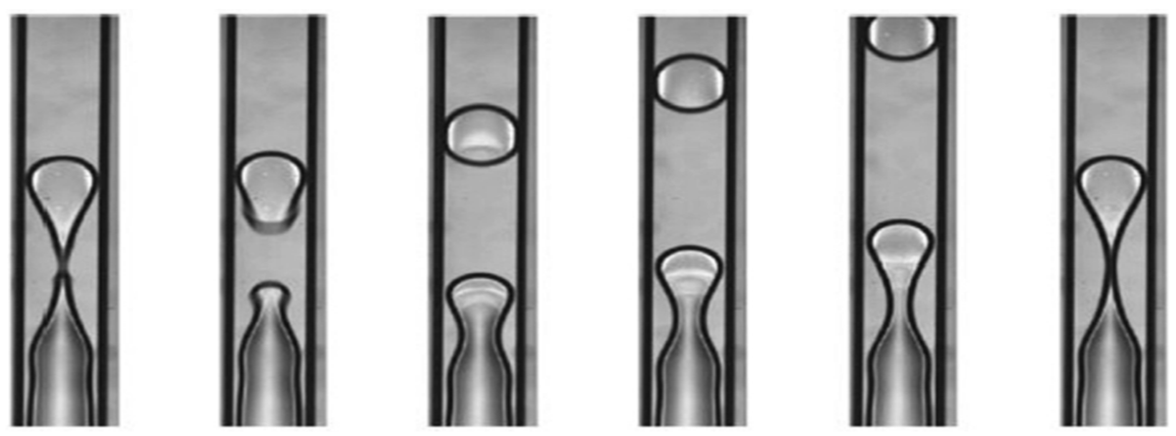
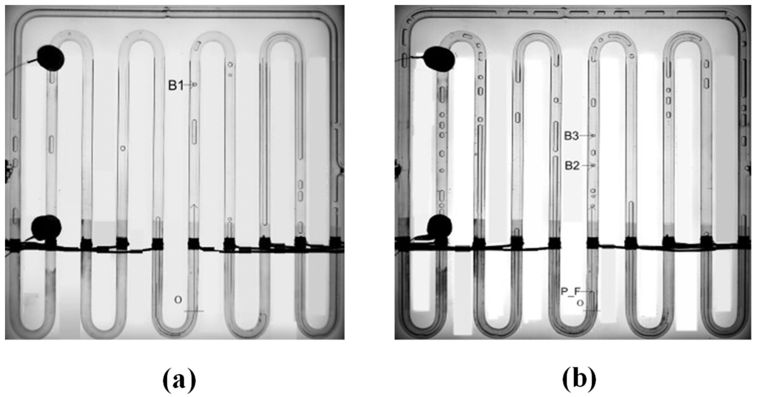
Qu et al. [93] visualized micro-pulsating heat pipes (MPHPs) with varying hydraulic diameters (251 μm, 352 μm, 394 μm) and revealed distinct flow patterns for each size. During the visualization process, they found an intriguing “injection flow” phenomenon in the condenser of 394 μm MPHPs, a previously unreported occurrence, as shown in Figure 3.
Yang et al. [94] conducted simulations to understand the temperature fluctuations in the evaporator and condenser sections of closed-loop pulsating heat pipes with diameters ranging from 1 to 5 mm and water as the working fluid. Their findings revealed that the PHPs with a diameter of 3 mm exhibited a higher heat-carrying capacity and superior heat transfer performance. Wu et al. [95] studied the heat transfer performance of pulsating heat pipes with different inner diameters (1 mm, 1.5 mm, 2 mm) and filling ratios (40–70%). The experimental results showed that when the filling ratio is about 50% and the heating power is 70 W, the thermal resistance of the PHPs with 1.5 mm inner diameter is the lowest, which is 0.1184 °C/W. Lee et al. [96] reported that the operating limit where the thermal performance significantly deteriorates increases with the increase of hydraulic diameter in both cross-sectional shapes (circular or square).
PHPs benefit from an easier start-up in a horizontal orientation due to the pressure imbalance caused by the non-uniform cross-section of the channels. Factors such as surface tension, working fluid properties, vaporization space, and nucleation space contribute to this imbalance between the channels. Yang et al. [97] tested two silicon-based micro-pulsating heat pipes with HFE-7100 as the working fluid, containing uniform channels (0.8 m) and non-uniform channels (0.6 mm or 1.0 mm), respectively, and tested them in both horizontal and vertical orientations with different heating powers. They found that in the horizontal direction, regardless of the channel type, they could not start, mainly due to the lack of gravity assistance in microchannel PHPs at 1–7 W. However, in the vertical direction, with the increase in heating power, they could start, and the junction temperature change of the non-uniform channels was more unstable. Chien et al. [98] compared the heat transfer performance of PHPs with uniform and non-uniform diameters. They found that the PHPs with uniform channels could not start in the horizontal direction; it was only when the filling ratio was at 50% and the heating power was 50 W that the pulsating heat pipes with non-uniform channels could start.
Markal et al. [30] designed plate pulsating heat pipes with channel widths of 2–2 mm, 2–1.5 mm, and 2–1 mm, all having a height of 2 mm, as shown in Figure 4. They observed that in the horizontal orientation, the thermal resistance of the uniform heat pipes remained almost unchanged, whereas the thermal resistance of the two non-uniform heat pipes decreased, indicating better heat transfer performance. This suggests that the non-uniform design can mitigate the influence of gravity. Additionally, reducing the channel diameter increases the evaporative momentum force, which is a crucial factor in enhancing the performance of non-uniform PHPs. In a separate study [31], a PHP with a gradually tapered structure was developed, which promotes fluid circulation and remains less sensitive to variations in inclination angle. This feature is particularly advantageous for ensuring the stable operation of PHPs across different angles of inclination.
Differences in the cross-section shape also affect the heat transfer performance. Ishida et al. [99] compared the effects of round tubes and square channels on PHPs. They found that the thermal performance of the square channel was worse than that of the circular channel. They attributed this to the presence of dry areas on the flat surface in the square channel, which deteriorated heat transfer. Lee et al. [96] investigated the operating limit of MPHPs for various channel geometries, including cross-sectional shapes and hydraulic diameters. Either circular or square channels with hydraulic diameters of 390 μm, 480 μm, and 570 μm were engraved on a silicon wafer to form a closed loop with five turns. They found that at the same hydraulic diameter, the maximum allowable heat flux of the square pipes was 70% higher than that of the round pipes. Moreover, the liquid film thickness of the square tube was obviously higher than that of the round tube. Another study [100] was conducted involving an experimental investigation of the impact of transverse grooves in channels on the heat transfer efficiency of flat pulsating heat pipes (FPHPs). Their findings revealed that these grooves significantly enhance the heat transfer capabilities of PHPs. Specifically, the thermal resistance was reduced by a substantial 34.6%, and the average thickness of the liquid film decreased by 69.2%, which in turn accelerated the film evaporation heat transfer rate. Different shapes of cross-sections with different capillary effects will result in varying liquid film thicknesses, which will have a certain impact on the flow phenomena and even heat transfer.

2.2.2. Length of Each Section

The relative length of each section in PHPs affects the heat transfer performance. It is certain that PHPs perform better when the amount of heat flux supplied in the evaporator is fully dissipated in the condenser region [95]. Reducing the condenser’s length diminishes the effective area for heat exchange. Therefore, we always want the condenser length to be greater than the evaporator length.
Wang et al. [101] used Computational Fluid Dynamics (CFD)to study the influence of the length ratio of the evaporator to the condenser on the start-up and thermal performance of PHPs. The results showed that increasing the length ratio of the evaporator to the condenser led to accelerated start-up speed of CLPHPs and reduced thermal resistance. However, dry-out easily occurs in CLPHPs at lower filling ratios and higher input powers. Su et al. [102] investigated the effects of heat transfer distance on temperature fluctuations. They monitored temperature variations at three distinct distances (375 mm, 575 mm, and 775 mm) while keeping the inclination angle and filling ratio constant. Their study revealed that as the heat transfer distance increases, thermal resistance also increases. Moreover, shorter distances exhibited higher frequency temperature oscillations with smaller amplitudes, indicating a more efficient heat transfer process. Kim et al. [103] experimentally investigated the effect of the condenser length on the thermal performance of MPHPs at various condenser temperatures. They observed the impact of varying the condenser temperature between 0 °C and 80 °C on a ten-turn MPHP. The study revealed that the ideal length of the condenser in micro-pulsating heat pipes fluctuates with different condenser temperatures. When the condenser temperature was low, the evaporator temperature decreased as the decrease in condenser length. Conversely, when the condenser temperature was high, the evaporator temperature increased as the decrease in condenser length.

2.2.3. Number of Turns

The number of turns is an important geometric parameter of pulsating heat pipes. It is believed that PHPs are more feasible to start up with lower heat input. Sun et al. [38] studied the effect of the number of turns on PHPs by testing two hydrogen closed-loop PHPs with two turns and five turns under different liquid filling ratios and heat flows. They indicated that the effective thermal conductivity of the two-turn PHPs is higher than the five-turn PHPs at each filling ratio. But the thermal resistance of the two-turn PHPs is larger than that of the five-turn PHPs due to the smaller heat transfer area. If the two-turn PHPs are scaled up by 2.5 times to a total of five turns, they will outperform original five-turn PHPs in terms of thermal resistance and effective conductivity. Lyu et al. [40] conducted a similar experiment, comparing serial–parallel 24-turn helium PHPs with 4-turn helium PHPs and serial 24-turn helium PHPs. The results showed that the 24-turn series–parallel helium PHP exhibits the smallest temperature gradient and the smallest thermal resistance. Secondly, the main advantage of the serial–parallel 24-turn helium PHPs is able to transfer very high heat loads under cryogenic operating conditions. Li et al. [45] compared the effect of 8 turns and 48 turns on the heat transfer performance of helium-pulsating heat pipes. They found that increasing the number of turns from 8 to 48 enhances the heat transfer capacity of the PHPs, but the maximum effective thermal conductivity decreases. However, they defined the 48-turn configuration (as shown in Figure 5) and found that the heat transfer capacity and effective thermal conductivity are better in a vertical parallel configuration than in a series configuration.
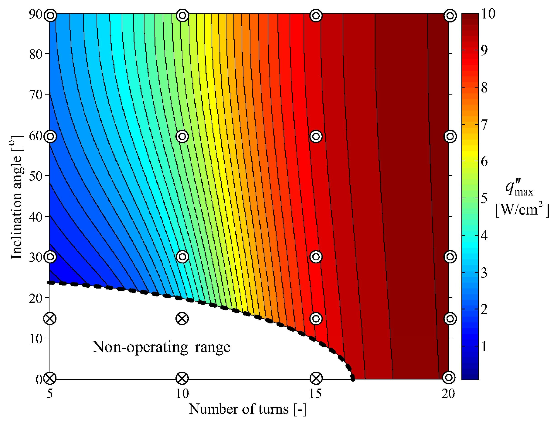
Lee et al. [104] fabricated 5-to-20-turn MPHPs (as shown in Figure 6) with FC-72 as the working fluid and a filling ratio of 50%. They found that the direction dependence of the maximum allowable heat flux weakens as the number of turns increases. The 20-turn MPHP had almost the same maximum allowable heat flux regardless of the inclination angle. Panyoyai et al. [105] studied the effect of the number of bending turns on the performance limit of inclined closed-loop oscillating heat pipes. They found that 5 to 15 turns did not affect the maximum heat flux. Charoensawan et al. [106,107] found that the optimal heat transfer performance of the PHP occurs with 26 turns. They pointed out that pulsating heat pipes are also influenced by factors such as the working fluid, tube diameter, and evaporator temperature. It is noteworthy to mention that the critical number of turns varies in different studies, and there is no common conclusion on the determination of the critical number of turns.

2.2.4. Surface Modification

The design of the internal surface of pulsating heat pipes involves a comprehensive consideration of many factors, including hydrophilic, hydrophobic, and surface roughness factors. Aluminum is a low-cost material with high thermal conductivity, widely used in heat dissipation devices. However, when water is used as the working fluid in aluminum heat pipes, it can produce hydrogen, which seriously affects the heat transfer performance of pulsating heat pipes. Xie et al. [108] plated a layer of chromium on the inner surface of aluminum PHPs. The results showed that there is a decrease in the thermal resistance of the aluminum–water PHPs as the heat power and operating temperature increase. However, chromium is too expensive, so it is not suitable for large-scale applications. Kim et al. [109] modified the surface wettability of aluminum pulsating heat pipes using the micro–nano corrosion method to improve the thermal properties and durability of water–aluminum PHPs. Wang et al. [110] obtained the heat transfer performance of three-dimensional closed-loop pulsating heat pipes with different wettability through numerical simulation. They found that the thermal resistance of the hydrophobic surface was lower than that of the hydrophilic surface at low heat load, while the reverse was true at high heat input. Furthermore, due to lower flow resistance and the effect of liquid film, CLPHPs with hydrophilic surfaces can effectively raise the anti-dry-out ability. Hao et al. [111] compared the effects of super hydrophilic and hydrophilic surfaces on the flow behavior and heat transfer performance of PHPs. The results revealed that the hydrophilic surface enhances the interaction between the fluid and the inner wall of the pipes during evaporation, improving the flow efficiency of the liquid inside the heat pipes and facilitating the start-up of pulsating heat pipes. Additionally, the hydrophilic surface increases the maximum displacement and velocity of the liquid slug. Leu et al. [112] compared the effects of different surface properties (unmodified surface, super hydrophilic surface, superhydrophobic surface, mixed hydrophilic and hydrophobic surface) on the internal flow behavior of PHPs. Significant changes in flow behavior were observed in the pulsating heat pipes with a mixed hydrophilic and hydrophobic surface. Specifically, continuous vapor slug flow was formed in the evaporator section, while laminar flow was observed in the unmodified surface PHPs. This maintains a higher vapor pressure in the evaporator section, and the stable flow direction can improve the start-up characteristics of the heat pipes, making them more reliable and efficient during start-up.
Ishida et al. [99] compared the influence of 1 mm circular tube internal roughness on pulsating heat pipes, as shown in Figure 7a. They found that the effective thermal conductivity values of rough circular tubes are larger than those of smooth circular tubes. They considered that roughness enhances wettability and expands liquid film widely on the inner surface. As a result, thermal performance was enhanced. Wu et al. [113] compared the effects of a sintered core versus an unsintered core on PHPs, as shown in Figure 7b. They found that the addition of a sintered powder core improved nucleation boiling in the evaporator, thereby enhancing the thermal driving force, and provided additional capillary action to facilitate liquid backflow into the evaporator. Qu et al. [114] proposed a micro-slot structure for PHPs, as shown in Figure 7c. This modification led to a reduction in the required starting power for the pulsating heat pipes when oriented vertically.
Structure optimization can involve the inner diameter, cross-sectional structure, length of each section, number of turns, and surface characteristics. When the inner diameter is small, drying out is prone to occur, while with a larger inner diameter, the thermal siphoning effect may occur. Generally, 1–3 mm is chosen. Adding micro-groove structures to the channels can easily generate nucleation sites, enhancing heat transfer performance. Furthermore, PHPs with non-uniform channel designs are easier to start. Appropriately increasing the proportion of the length of the condensation section in PHPs can help improve the heat transfer capability of PHPs. The number of turns does not have a range at present, but there is a critical number of turns in different operating conditions. A superhydrophilic surface design for the evaporation section and a superhydrophobic surface design for the condensation section can reduce the occurrence of drying out.
In the study of structural parameters, researchers have significantly improved the start-up speed and heat transfer efficiency of PHPs by optimizing the inner diameter, inner surface, and number of turns. However, designing and optimizing the inner diameter and surface of PHPs in extreme environments, as well as maintaining low flow resistance and high heat transfer efficiency with a reduced inner diameter, remain challenging issues. Additionally, the long-term durability of different surface modification methods needs further investigation. These are topics worth exploring in future research.

2.3. Operation Conditions

The operation conditions of PHPs may be different and they have great influence on the heat transfer performance of PHPs. In this section, we define two types of operation conditions, i.e., with and without motion, i.e., with and without the consideration of centrifugal force. Moreover, the research on PHPs with different heating modes is also summarized.

2.3.1. Status without Motion

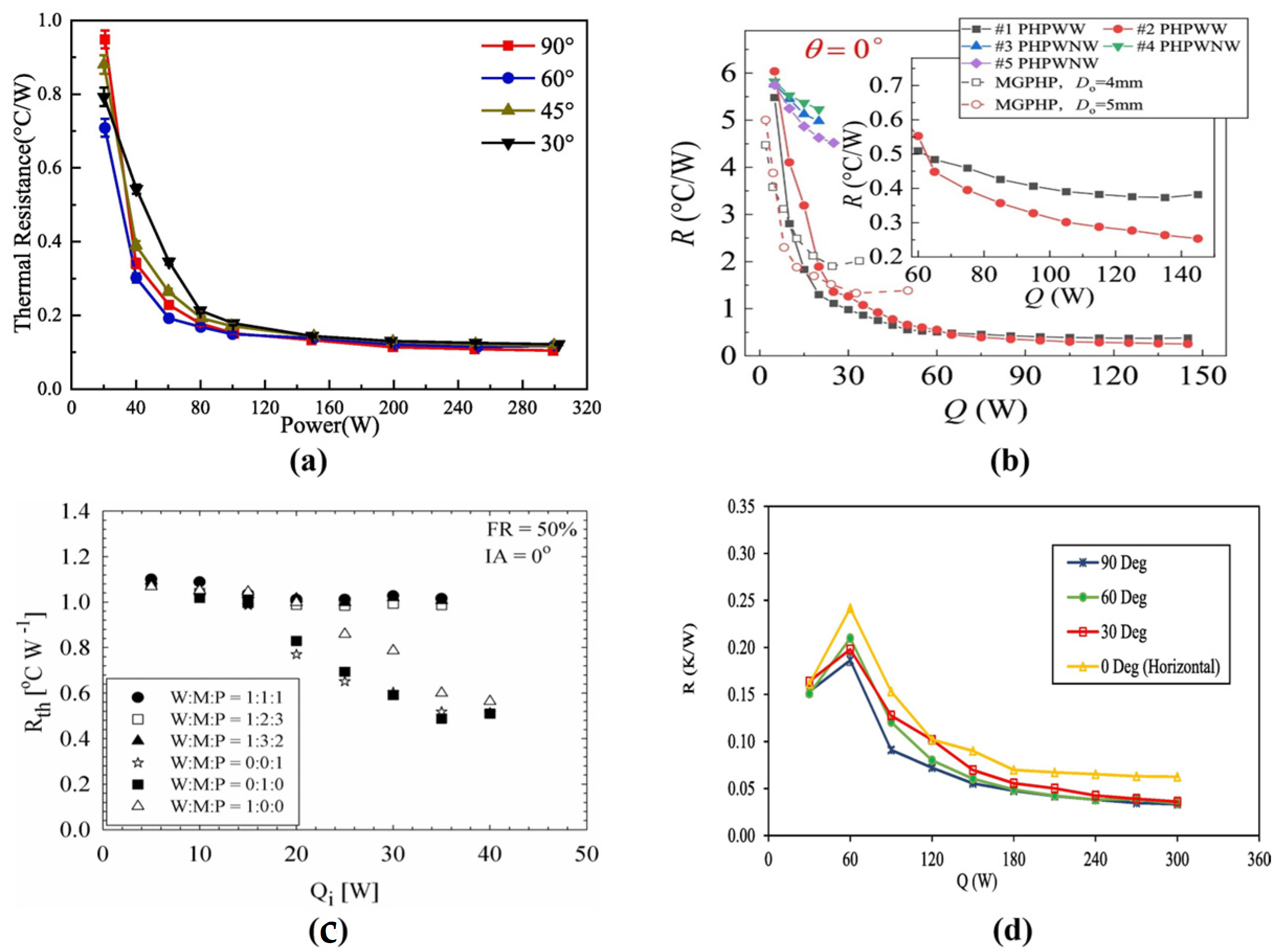
Although motion and, accordingly, centrifugal force are not involved in the performance investigation of PHPs, recent research has highlighted the significant impact of gravity on the heat transfer efficiency of PHPs. The incline angle of PHPs emerges as a key factor influencing this efficiency, as the gravitational effect varies with the angle. An optimal incline angle is crucial for achieving the best performance. Saha et al. [17] found that closed-loop pulsating heat pipes (CLPHPs) exhibited peak heat transfer performance when inclined at an angle between 50° and 70°, attributed to the higher bubble rise velocity occurring within this range, which enhances the heat transfer rate. As the inclination angle increases, the velocity of bubbles also increases, leading to pointed bubble heads with higher velocities. At 45°, the velocity peaks, and beyond that, as the inclination angle further increases, the bubble heads start to blunt, causing a decrease in bubble velocity. This observation has been experimentally confirmed by Cheng et al. [115] and Bhusan et al. [116]. Qu et al. [117] found that 3D pulsating heat pipes exhibited the best heat transfer performance at an inclination angle of 60°, as shown in Figure 8a. Consequently, when the heat input ranged from 20 W to 100 W, three-dimensional pulsating heat pipes (3D-PHPs) at 60° have minimized thermal resistance. Additionally, the thermal resistance of 3D-PHPs under all working conditions was similar when the heat input exceeded 150 W, indicating that the thermal driven force was strong enough to achieve the annular flow stage. Alizadeh et al. [57] indicated that in other modes, as the input power increases, the thermal resistance decreases, but the lowest thermal resistance is always associated with the vertical mode. Xue et al. [118] studied the relationship between the flow patterns and thermo-hydrodynamics of PHPs. They found that the gravity effect on the flow performance of PHPs is dramatic in a low- power state. However, it decreases rapidly and can be neglected as the flow pattern of PHPs changes into “Annular Flow”.
In the horizontal operation modes, Saha et al. [17] observed that the temperature of the evaporator kept climbing as the inclination angle decreased from 90° to 0° under consistent operating conditions in the horizontal direction. The system could not function properly when the angle reached 5°. When the system is horizontal, the liquid struggles to flow back to the evaporator, causing dry-out. Wu et al. [113] noted that the thermal resistances of PHPs without integral inner-wall sintered powder wicks increased at an inclination angle of 0°. The heat transfer performance worsened because gravity’s positive effect on the unbalanced pressure distribution and liquid flow-back weakened. However, PHPs can be successfully start up at all inclination angles when adding a sintered core, as shown in Figure 8b. Markal et al. [119] found that when heat pipes are placed horizontally, as shown in Figure 8c, the thermal resistance data for the ternary mixture are distributed horizontally. This indicates that FP-CLPHPs equipped with any ternary mixture cannot operate effectively in a horizontal position. Betancur et al. [120] found that the system could only start up with FR 37.5 and 50% in the horizontal position. The oscillations had larger amplitudes in the horizontal position, and a higher heat flux was needed to maintain sustained oscillations. The thermal resistance was more significant compared to devices operated in the vertical position, even when fully activated. Xue et al. [121] found that ammonia CLPHPs can easily start up at a low input power in horizontal operation, but it is difficult to achieve circulation. The capillary in the evaporate section will burn out once the input power increases, leading to higher thermal resistance and a decrease in transfer performance.
However, Qu et al. [114] found that adding micro-groove structures in the horizontal direction can lower the limitations of heat transfer. Qu et al. [93] also investigated the start-up, heat transfer, and flow characteristics of trapezoidal silicon micro-pulsating heat pipes (MPHPs) with three diameters. It was found that the thermal performance tends to decrease when the MPHPs are shifted from the vertical to horizontal direction. Additionally, when R113 or FC-72 is used as the working fluid, the system can start within 200 s. However, when filled with water or ethanol, it cannot start at any angle. Lee et al. [104] found that when the number of turns is 20, the inclination angle from vertical to horizontal does not affect start-up. Alizadeh et al. [57] found that the thermal resistance does not suddenly increase with high input heat flux after applying a magnetic field in the horizontal position. It occurs the dry-out phenomenon, and the magnetic field can compensate for the effect of gravity, as shown in Figure 8d. The major phenomena are listed in Table 4.

2.3.2. Status with Motion

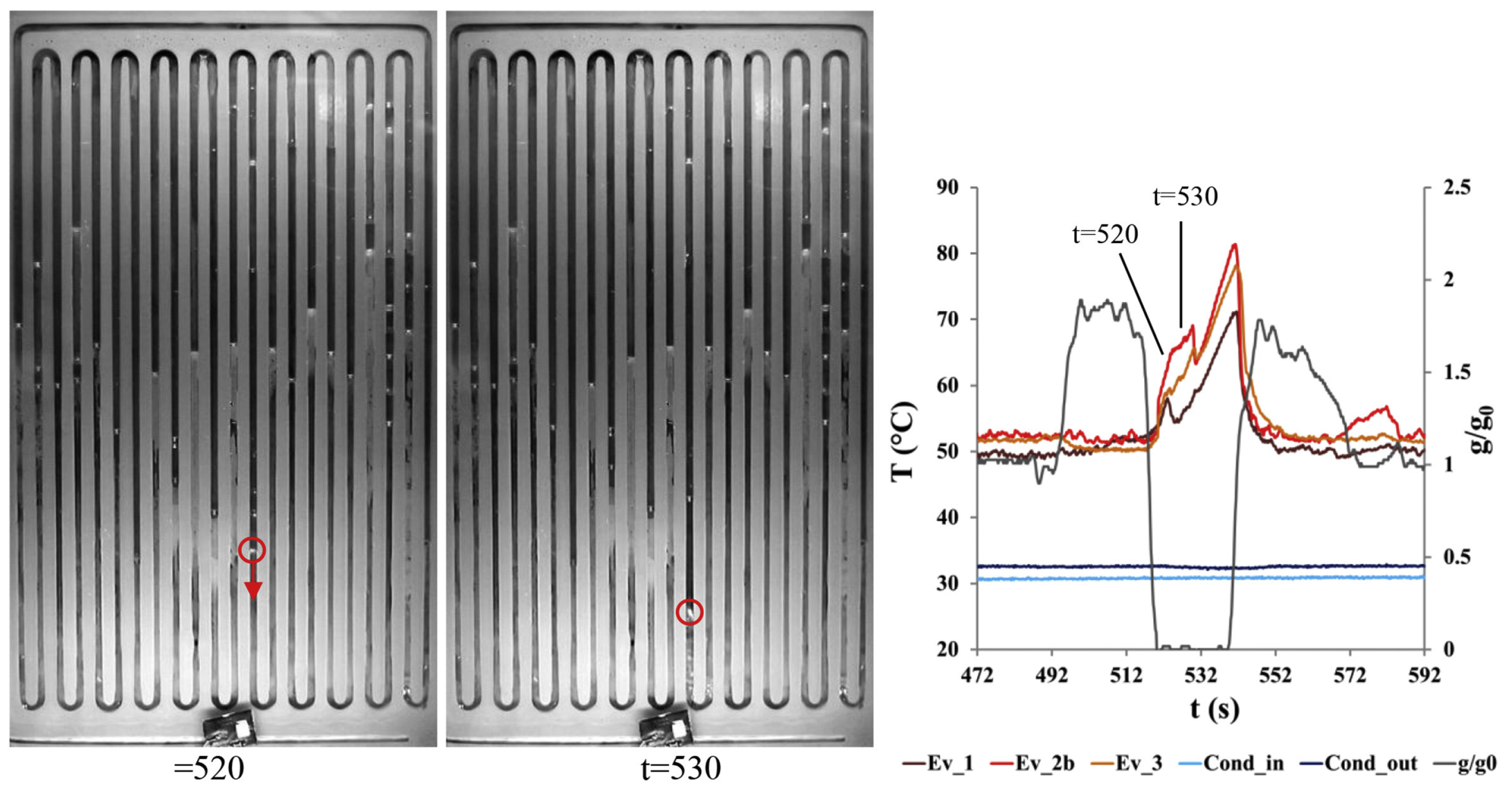
In status with motion, the combination of centrifugal force and gravity affects the performance of PHPs simultaneously. The major phenomena during motion are summarized in Table 5. In space, pulsating heat pipes need to operate effectively in microgravity conditions. Parabolic flight experiments are adopted to conduct experiments with microgravity [9,122,123]. Mameli et al. [9] observed a sudden temperature increase in the evaporator section of pulsating heat pipes during microgravity, but intriguingly, this effect was reversible during the subsequent hypergravity phase. Maksym et al. [124] observed a similar temperature increase in PHPs filled with ethanol under microgravity conditions. This phenomenon was attributed to the transition of the liquid plug’s movement from slug flow to annular or semi-annular flow, known as re-activation phases, triggered by pressure fluctuations or other influences. Interestingly, this transition ultimately restored the heat pipe’s heat transfer capabilities, as shown in Figure 9. Lastly, Mauro et al. [123] investigated the stable operating condition of large-diameter PHPs under microgravity conditions. Their findings revealed that PHPs can maintain stable operation at a thermal input of 185 W. Cecere et al. [22] investigated flat-plate PHPs utilizing water and a self-replenishing wetting mixture (water/n-butanol) as working fluids under variable gravity conditions. They observed that water is unable to operate in low-gravity environments, whereas PHPs filled with the self-replenishing wetting fluid can still operate normally during the microgravity phase, as shown in Figure 10. In addition, Sun et al. [125] discovered that the heat transfer performance of PHPs is less dependent on the diameter and length of the pipe under microgravity, but the temperature has a greater impact than the diameter and length of the pipe.
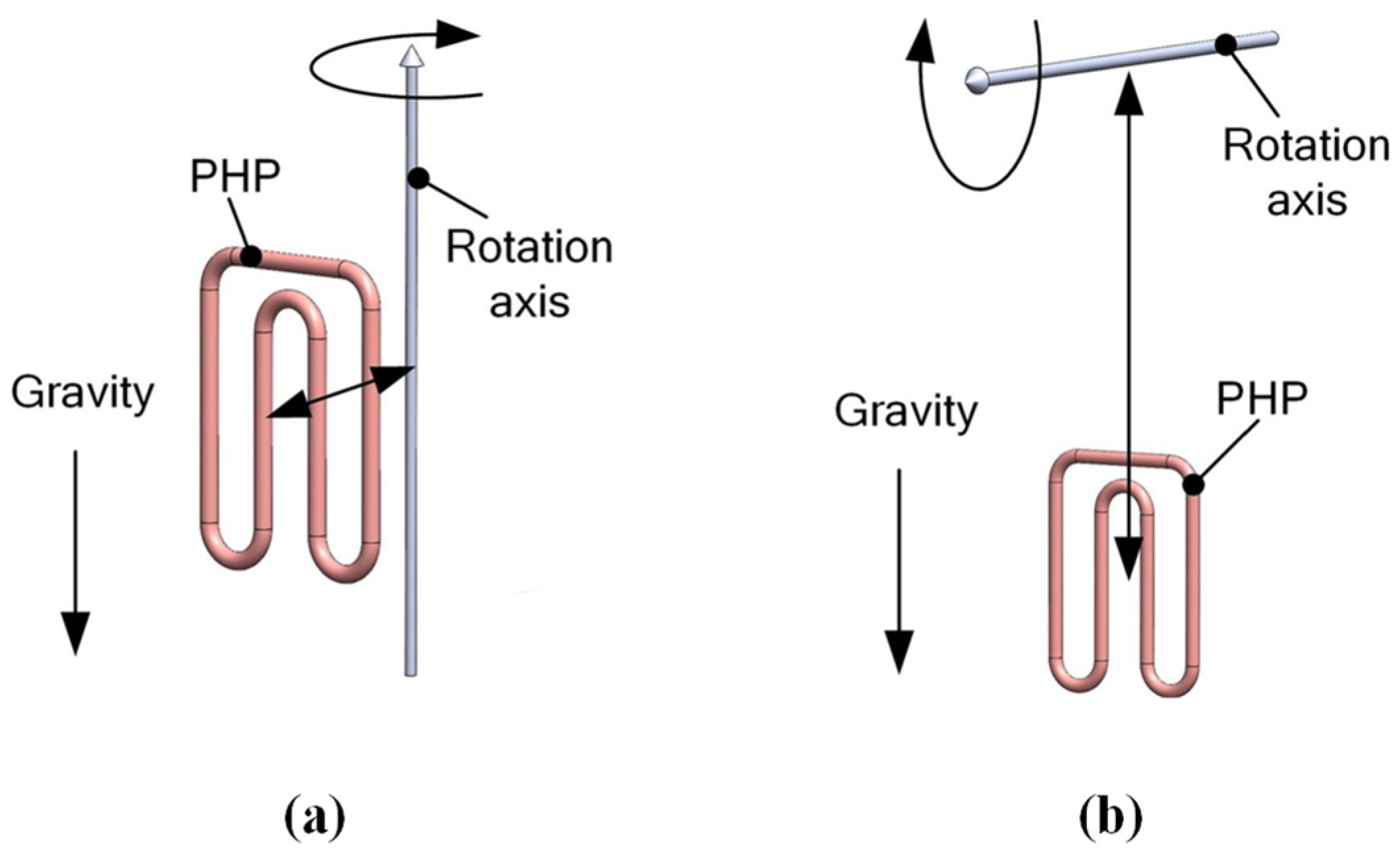
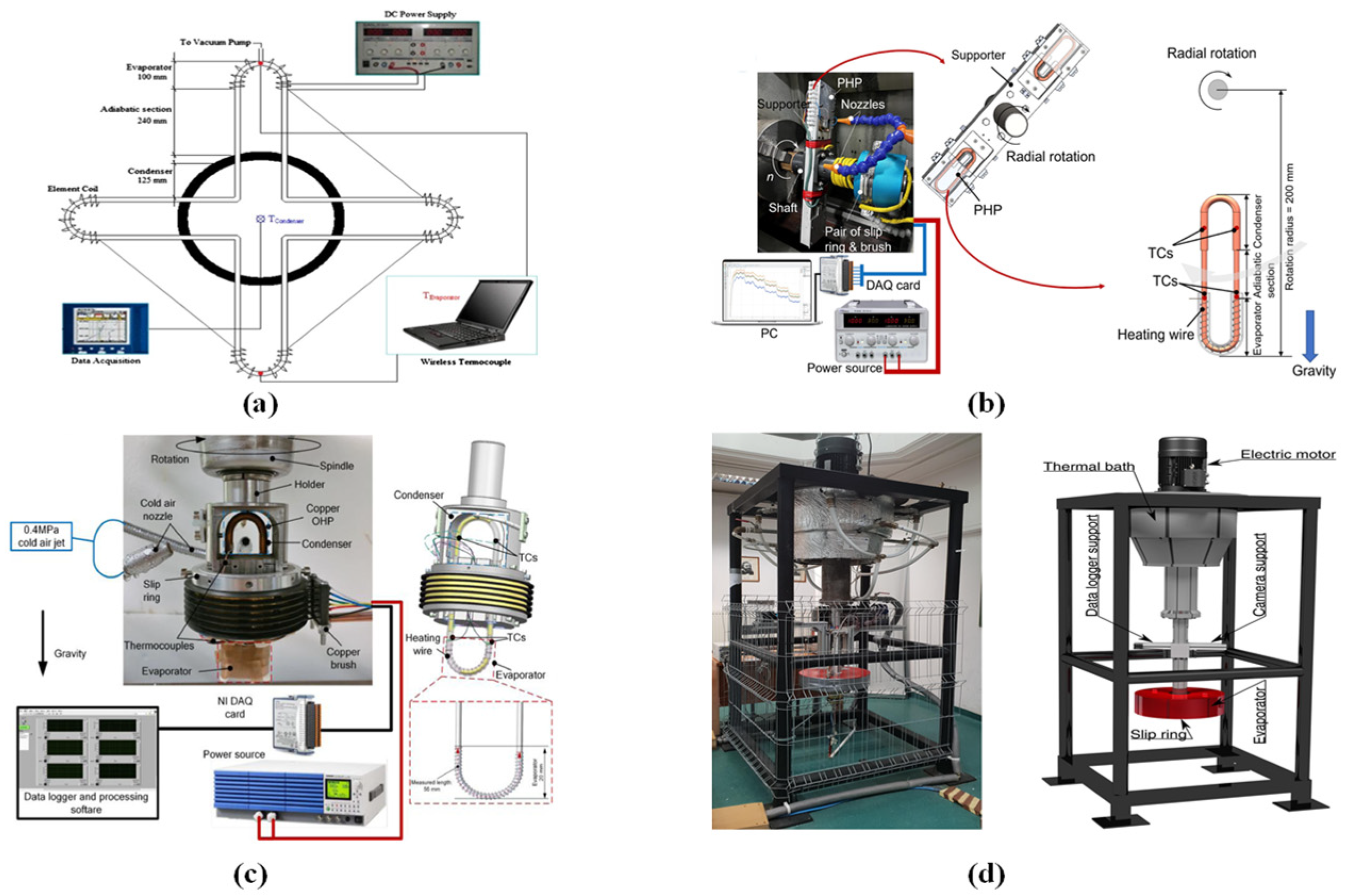
When centrifugal force is unneglectable, the performance of PHPs is influenced comprehensively by centrifugal force and gravity. Categorized by the directions of gravity and centrifugal force, the PHPs with motion status can be divided into two cases: (1) axial rotation and (2) radial rotation [126]. In the first case, centrifugal force is always perpendicular to gravity, and centrifugal force always stays on the surface determined by the directions of gravity and the rotation axis. In the second case, centrifugal force can be at any angle with gravity and the axis is perpendicular to the surface where the centrifugal force and gravity are (as shown in Figure 11).
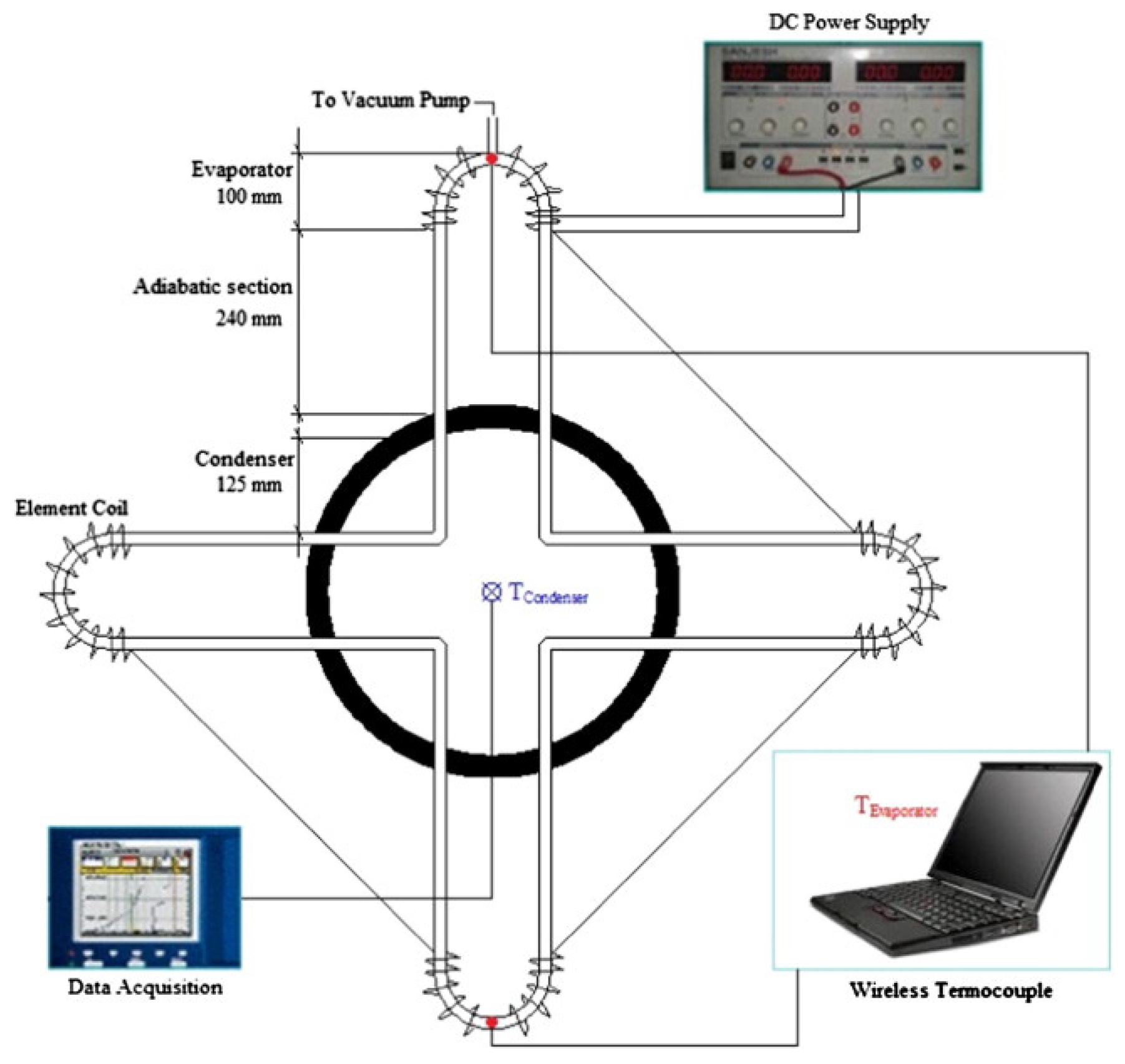
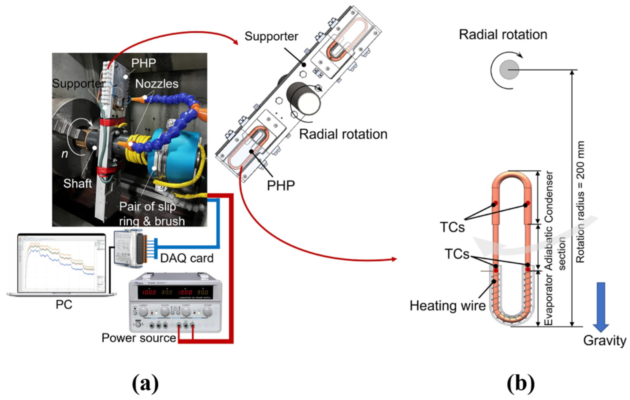
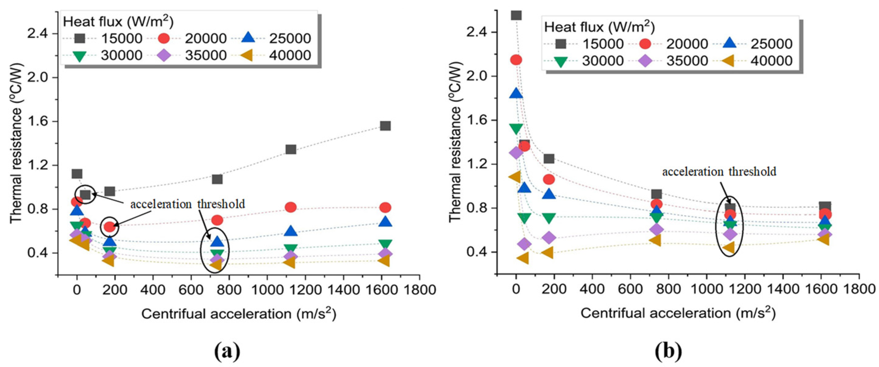
Aboutalebi et al. [127] studied the influence of radial speed on the heat transfer performance of rotating closed-loop pulsating heat pipes (RCLPHPs) in radial mode, as shown in Figure 12. The results indicated that there is a gradual decrease in the thermal resistance of the PHPs as the rotational speed increases because more fluid can return to the evaporator after being condensed, and this not only reduces the possibility of dry-out phenomena but also speeds up the heat transfer rate. In particular, the heat transfer performance of the PHPs is improved significantly at high input powers. Dehshali et al. [5] investigated the heat transfer performance of rotating closed-loop pulsating heat pipes (RCLPHPs) under different radial speeds. The results showed a lower thermal resistance in motion mode compared to stationary mode. Moreover, they indicated that with the increase in radial speed, the liquid could return to the evaporator section faster, and the vapor slug could be pushed to the condenser section faster. So, there is an increase in the thermal resistance as the speed increases. In particular, there is a decrease in the possibility of drying out at the top and bottom positions of the pulsating heat pipe. On-ai et al. [128] evaluated the heat transfer performance of rotating closed-loop pulsating heat pipes (RCLPHPs) by measuring the working fluid temperature amplitude and frequency under different radial accelerations and heat inputs to determine the operating status. The results indicated that with the increase in acceleration, the temperature amplitude decreased and the flow pattern changed from an annular flow to a slug flow, and the flow direction of the working fluid inside the heat pipes transformed from oscillatory flow to stable cyclic flow. When the heat input increases, the temperature amplitude increases, the flow pattern changes from a slug flow to an annular flow with intermittent liquid slug, and the flow direction is always a circulatory flow corresponding to the magnitude of the centrifugal acceleration, thereby enhancing the overall performance of the heat pipes. In addition, the RCLPHP showed a slug-train flow pattern, the same as the ordinary CLPHP, during high centrifugal acceleration. Qian et al. [126] investigated the heat transfer performance of rotating closed-loop pulsating heat pipes (RCLPHPs) containing acetone and deionized water under high radial centrifugal acceleration, as shown in Figure 13. The tests revealed that there is an acceleration threshold with the increase in radial centrifugal acceleration. And the acceleration threshold increases with the increase in heat flux. Below this threshold, the thermal resistance exhibits an inverse relationship with the acceleration; above the threshold, the thermal resistance will remain either constant or inversely proportional to the acceleration. The vapor and liquid phases can be separated to some extent by centrifugal force, and the increase in heat flow can slow down this phenomenon. So, there is a higher acceleration threshold under large heat flux. Acetone with lower surface tension has a lower acceleration threshold, as shown in Figure 14. Moreover, the acceleration threshold for DI water with higher surface tension is significantly larger. Finally, by considering the key parameters including the heat flux, centrifugal accelerations, thermophysical properties of the working fluid, dimensions, and working temperatures, a semi-empirical correlation of dimensionless numbers was built to estimate the heat transport. And the difference between the correlation values and the experimental results was less than 10%.
Table 5. The phenomena during motion of PHPs.
ConditionPhenomenonRefs.
Microgravity and HypergravityEvaporation temperature rises rapidly. Stop-over phenomena occur. Dry-out results in deterioration of heat transfer performance. Reactivation phenomenon leads to enhancement of heat transfer performance. Large inner diameter, self-replenishing wetting, and large temperature difference are essential for stable operation.[9,22,123,124,125]
Centrifugal forceHeat transfer is enhanced with acceleration in rotation less than the threshold value. However, heat transfer performance is deteriorated once the threshold is exceeded.[5,126,128]
To the best of our knowledge, there is no clear determination of a threshold value that is valid for common cases, taking into account the variation in structure, accelerator range, working fluid, filling ratio, etc., in experiments.
Qian et al. [129] studied the influence of axial rotation on the heat transfer performance of single-loop axial-rotating pulsating heat pipes (ARPHP) filled with ethanol, acetone, and water, as shown in Figure 15. The findings indicated that as centrifugal acceleration increases, the thermal conductivity of ethanol and acetone show a corresponding increase. However, water has high flow friction due to its high dynamic viscosity, causing a deceleration in circulation flow once a specific threshold (a = 30 m/s2) of acceleration is surpassed. Ultimately, the dry-out phenomenon may occur, resulting in a decline in the thermal coefficient. Moreover, the correlation dimension and Lyapunov exponents of the evaporator are proposed to describe the amplitude of oscillation of temperature and determine the degree of chaos, respectively, as shown in Figure 16. A negative Lyapunov exponent corresponds to a stable fixed point, while when the Lyapunov exponent is equal to zero, it indicates a stable limit cycle; when the Lyapunov exponent is positive, it shows a chaos state in the ARPHP. And the correlation dimension changes of the ARPHP with acetone and water showed a consistency with the changes in the thermal performance. Qian et al. [130] discussed the heat transfer performance of single-loop rotating pulsating heat pipes with methanol as the working fluid under different coaxial rotational accelerations. The results showed that with the increase in centrifugal acceleration, there was a noticeable enhancement in the thermal coefficient of PHPs. But it was observed that the rate at which this enhancement occurred gradually diminished with the increasing centrifugal acceleration. And a novel model was developed to simulate and predict the heat transfer coefficient of axial rotating pulsating heat pipes based on experimental data and a grey model. The errors of results from Artificial Neural Network (ANN) models range from 3.36% to 16.6%, exhibiting a high level of accuracy and effectiveness.

2.3.3. Heat Input Mode

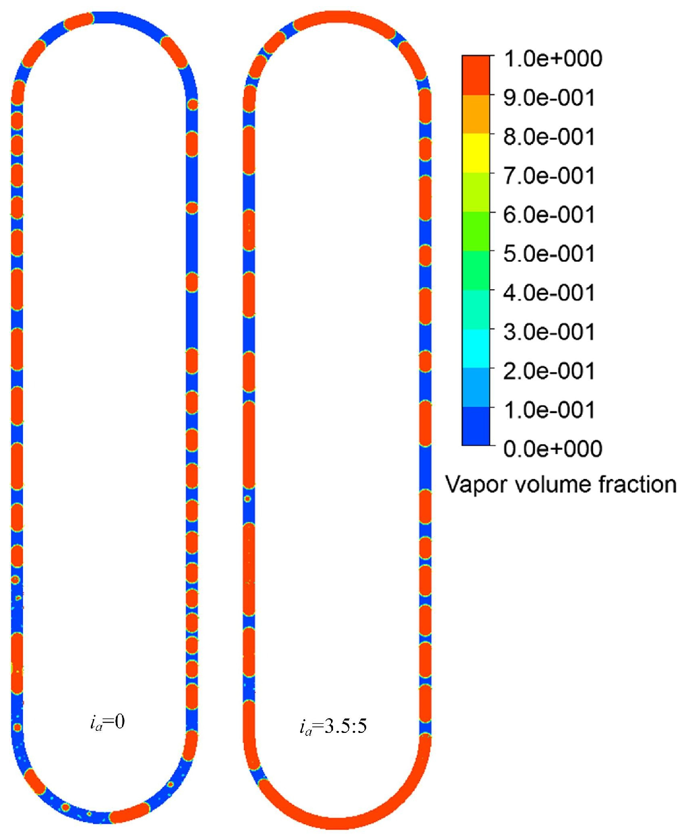
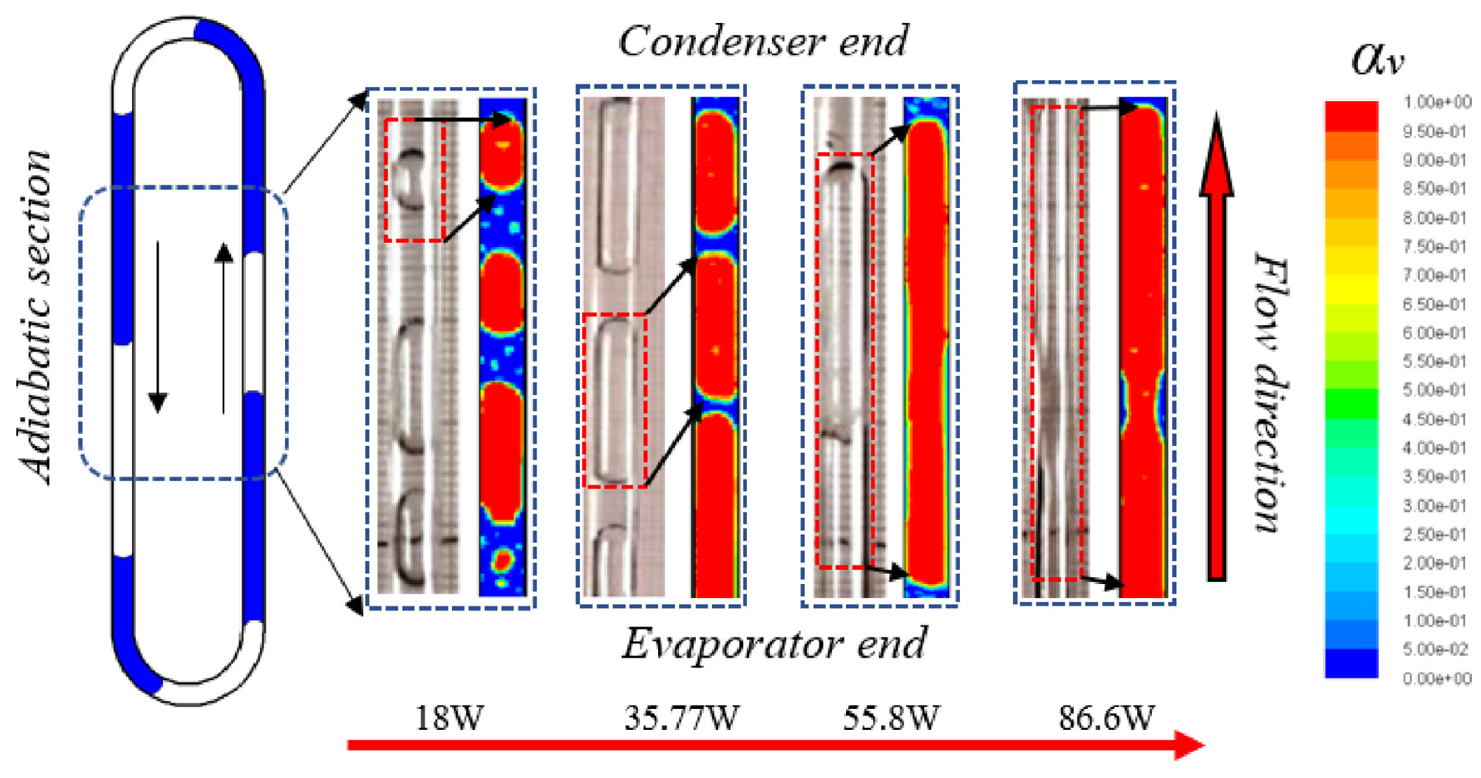
The start-up and operation of PHPs depend on supplying sufficient heating power to generate a steam pressure difference substantial enough to drive the working fluid flow. If this pressure difference is small, under certain operating conditions, PHPs may have difficulty starting. Therefore, the input mode is crucial for the operation and performance of PHPs, especially with the consideration of inconsistent heat flux, such as periodical mode and non-periodical heating mode, as well as non-uniform heating mode. Zhao et al. [131] utilized a mathematical model of PHPs to simulate three distinct heat source modes: non-uniform pulse, uniform pulse, and alternating heat sources. Their study unveiled the dynamics of the internal working fluid and the mechanisms behind enhanced heat transfer. The findings suggest that these heat source modes can boost the heat transfer capabilities of closed-loop pulsating heat pipes under particular circumstances. However, if the configuration conditions are not properly aligned, it can actually diminish the heat transfer performance and potentially destabilize the heat pipe’s operation. Xian et al. [132] indicated that pulse heating can effectively reduce the temperature difference between the evaporation section and the condensation section, thereby improving heat transfer efficiency. In another study [133] conducted by the same research group as ref. [132], they investigated the impact of pulsatile heating on PHPs. They observed a reduction in the liquid film thickness under pulsatile heating compared to continuous heating, indicating increased sensitivity of the vapor slug to temperature fluctuations in the pipe wall. This sensitivity led to a more pronounced oscillatory motion, as depicted in Figure 17. Furthermore, the application of small-pulse heating was found to expand the stable operating range of PHPs.
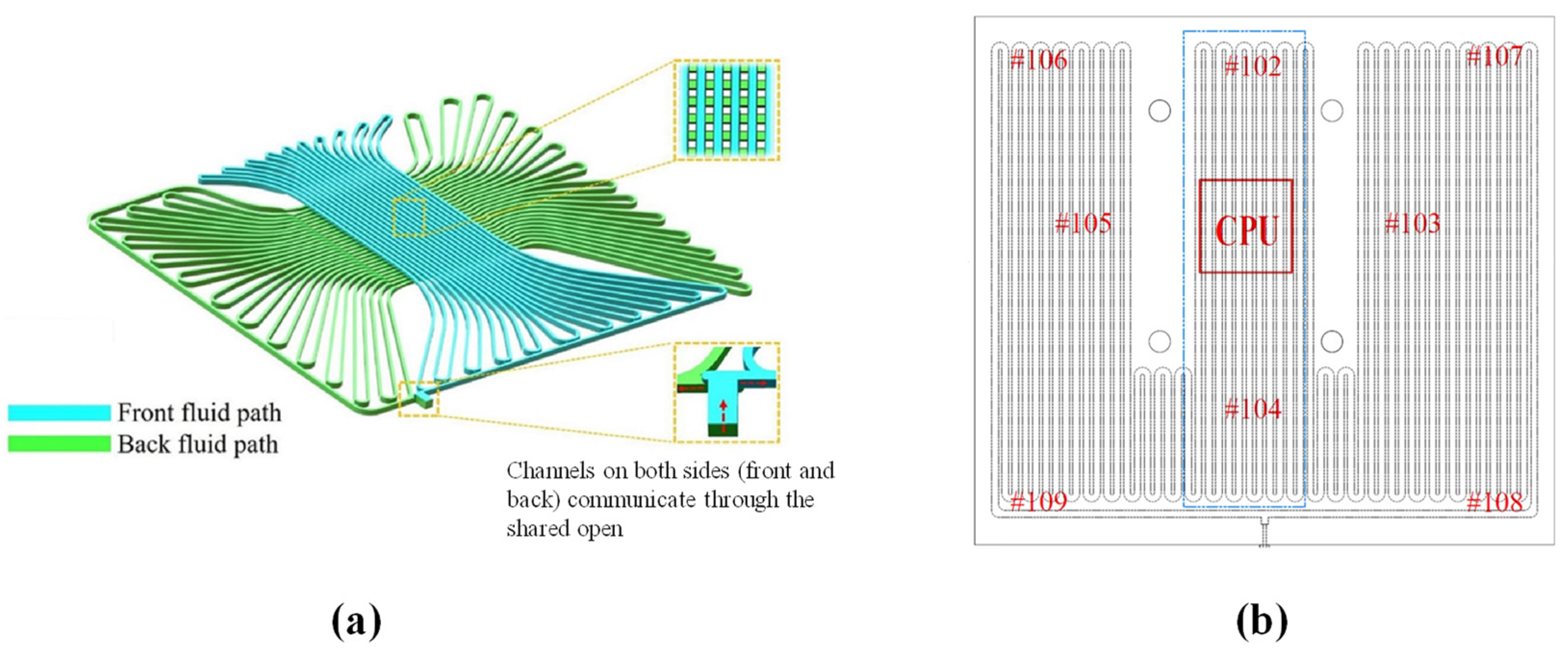
Wang et al. [134] enhanced the start-up of pulsating heat pipes by assisting heat flow to improve thermal management performance. They demonstrated that this approach effectively enhanced the thermal management performance of the battery by reducing thermal resistance, promoting the regression of local hot spots, and mitigating the risk of thermal runaway. However, selecting appropriate parameters is crucial to prevent excessive evaporator temperature. Li et al. [39] studied the effects of two heating modes (sudden heating and gradual heating) on hydrogen-pulsating heat pipes. The results showed that the pulsating heat pipes exhibited a stable heat transfer performance under both heating modes. Wang et al. [135] discovered that employing two heating modes, non-uniform and uniform, revealed that non-uniform heating pulsating heat pipes can start up quickly, while uniform heating exhibits better heat transfer performance during stable operation. Mameli et al. [122] found that non-uniform heating of the evaporator could enhance the heat pipe’s overall performance, particularly at lower heating powers. The major phenomena are listed in Table 6.
In terms of operating conditions, we mainly discussed conditions without motion, conditions with motion, and heating methods of PHPs. Currently, researchers have made significant progress in the heat transfer performance of PHPs both with and without motion. It has been found that PHPs exhibit optimal heat transfer performance at specific inclination angles, and experiments in microgravity environments have shown that PHPs can operate effectively in space. Additionally, it has been revealed that non-uniform heating methods can enhance the heat transfer performance of PHPs. However, maintaining stable operation of PHPs under extreme conditions remains a research challenge. Different studies have varying opinions on the optimal parameters for inclination angles, acceleration thresholds, and input heat source modes. These are all topics worth discussing in future research.

3. Mechanism of Pulsating Heat Pipes

Theoretical investigations may be useful for the performance estimation and optimization of pulsating heat pipes. By utilizing the physical model, researchers can gain profound insights into the operational principles of PHPs, thereby facilitating optimal design choices and parameter selection. Conducting numerical simulations and visualization experiments on PHPs can validate the accuracy of the physical model, thereby refining and enhancing the theoretical model of PHPs. Therefore, this section will elucidate the mechanism of PHPs through theoretical models, numerical simulation, and visualization experiments [16].

3.1. Theoretical Model of PHPs

Theoretical models play a crucial role in describing the oscillatory motion of PHPs and predicting their heat transfer performance. Several models have been developed for pulsating heat pipes, including spring–mass–damper models, massmomentum–energy equation models, semi-empirical models, and more. The heat absorbed in the evaporation section of pulsating heat pipes is primarily dissipated through the oscillating movements of liquid slugs and vapor slugs. The pressure difference generated within the pulsating heat pipes serves as the driving force for this oscillatory motion. The friction is considered as the resisting force for the motion. The expansion and shrinkage of vapor are also considered in some models.

3.1.1. Spring–Mass–Damper Model

The spring–mass–damping model was first proposed by Ma et al. [136] to predict the oscillating motion of PHPs, as given in Equation (3). It is based on Newton’s law that force is equal to mass times acceleration. The pulsating heat pipes are oriented horizontally, and the model utilizes the temperature differential between the evaporating and condensing sections as the primary driving force behind the oscillatory motion, with frictional and restoring forces considered but the gravitational force neglected.
( L 1 ρ 1 + L v ρ v ) A d 2 x d τ 2 + [ ( f l R e l ) ( μ l L l 2 D h 2 ) + ( f v R e v ) ( μ v L v 2 D h 2 ) ] A d x d τ + A ρ v R T L v x = ( A h fg ρ V , C T e ) ( Δ T max Δ T min 2 ) [ 1 + cos ( ω τ ) ]
where hfg, ω, τ, f, μl and μv are latent heat, frequency, times, friction factor, and liquid and vapor viscosity.
Liang et al. [137] presented a mathematical model describing the oscillation characteristics of slug flow in a capillary tube. They demonstrated that the gravitational force affects the frequency and amplitude of the oscillating flow motion in the capillary tube, as given in Equation (4).
m i d 2 z i d t 2 = Δ p i A Δ p fi A K i 1 ( z i z i 1 ) K i ( z i z i + 1 ) ρ l g A L l , i
where K is the stiff coefficient and Zi is the position of the ith liquid plug in the tube.
Ma et al. [138] proposed a model including the forced convection heat transfer effect caused by oscillating motion; the closed evaporation effect in the evaporation section and the thin film condensation effect in the condensing section are established to predict temperature, as given in Equation (5). The model takes into account the influence of operating temperature and non-linear vapor volume modulus. The results show that the input power and the temperature difference in the evaporating and condensing section are greater than the initial value, the oscillation motion starts, and the heat transfer is enhanced. Compared with the experimental results, it is found that the temperature is basically consistent with the predicted temperature.
( L l ρ l + L v ρ v ) A d 2 x d τ 2 + [ ( f l Re l ) ( μ l L l 2 D h 2 ) + ( f v Re v ) ( μ v L v 2 D h 2 ) ] A d x d τ + A ρ v R T L v ( x + x 2 L v + x 3 L v 2 + + x n L v n 1 ) = ( A h fg ρ υ , c T e ) ( Δ T max Δ T min 2 ) [ 1 + cos ( ω τ ) ]
Evaporative heat transfer model:
h = h mic + h mac
h mic = 0.00122 [ k l 0 . 79 c pl 0 . 45 ρ l 0 . 49 σ 0.5 μ l 0 . 29 h l υ 0 . 24 ρ υ 0 . 24 ] [ T w T sat ( P l ) ] 0.24 [ P sat ( T w ) P l ] 0.75 S
h mac = F ( X tt ) h l
Thin film condensation model:
Δ P l = 0 L c , v 2 ( f Re δ μ l D 0 q c 2 δ 3 D i ρ l h fg ) s d s
where S is a suppression factor, Xtt is the Martinelli parameter, and kl is thermal conductivity.
Spinato et al. [139] used the model of Ma et al. [138] to predict the oscillation frequency, but this prediction was inconsistent with the experimental results. This inconsistency arose because they assumed uniform temperature within the system, whereas temperature variations affect the density ratio, which significantly impacts the frequency increase.
A single damping model is used to understand the oscillation behavior of PHPs, but the model loses its effectiveness when the amplitude decreases during stable oscillation. This is not suitable for multi-turn PHPs with multiple liquid plugs.
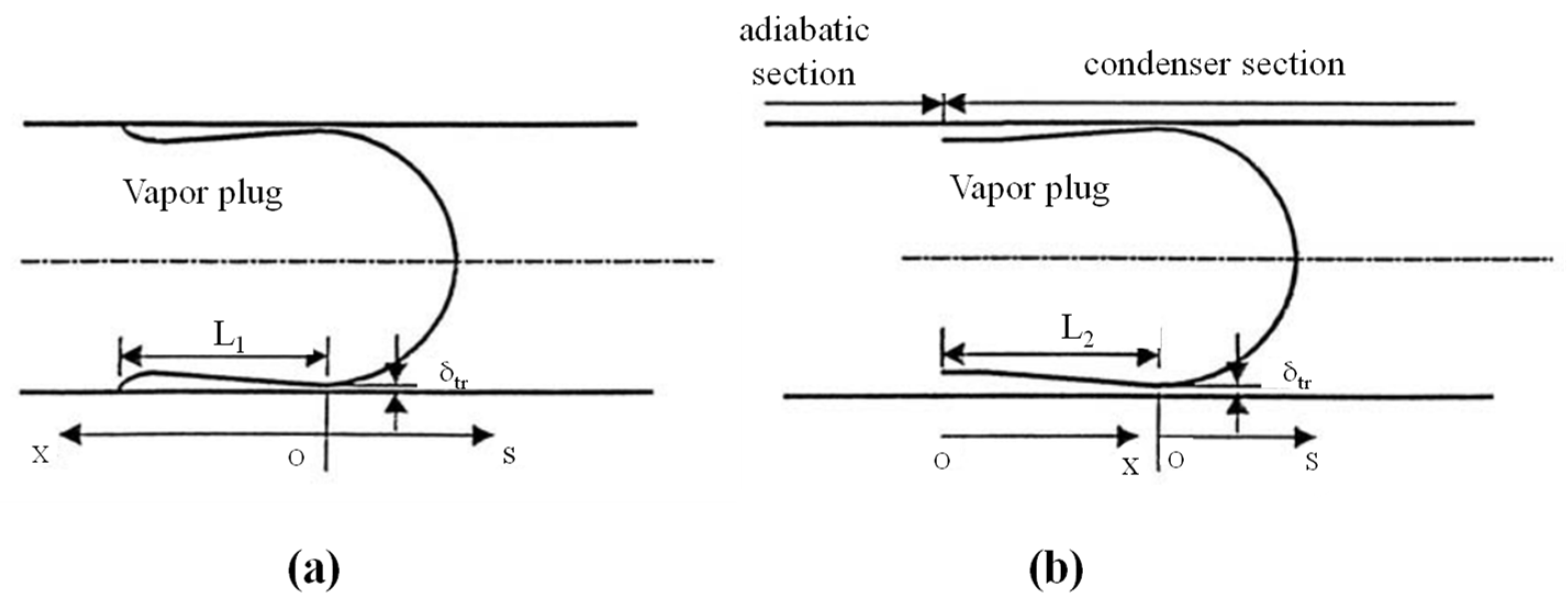
In these studies, the oscillation characteristics of multi-turn PHPs are theoretically analyzed using the spring–mass–damper model. Gürsel et al. [140] proposed a non-linear spring–mass–damper model to predict the motion of liquid slugs of PHPs with a non-uniform and asymmetric filling, as given in Equation (6). Liquid slugs, vapor plugs, friction, and capillary forces are represented by masses, non-linear springs, and non-linear dampers, as shown in Figure 18. They considered the capillary force and gravity effects. If ignoring these two factors, the model results will match the model of Ma et al. [136]. And they also conducted a comparison with experimental data from Khandekar et al. [141]; the simulation results indicate a high degree of consistency.
m l , i x ¨ i = F pres , i + F fric , i + F cap , i + F grav , i
where ml,i and i are the mass and acceleration of the ith liquid slug. Fpres,i, Ffric, Fcap,i, and Fgrav,i are the effective pressure force over a liquid slug, the friction force, the effective capillary force, and the gravitational force acting on the ith liquid slug, respectively.
Peng et al. [142] proposed a non-linear model based on the spring–mass–damping model, which accounts for the interphase mass-transferring effect, fluid filling ratio, different heating modes (top or bottom heating), gravity, bending pressure loss, properties of the working fluid, and different random distributions of initial velocities and lengths of fluid slugs. This model was designed to study the influence of the liquid plug length and PHP heat transfer. It can be used to simulate the dynamics and heat transfer of PHPs in detail and accurately, as given in Equation (7). Figure 19 shows the structure of a multi-turn pulsating heat pipe.
A L li ρ l s ¨ i = A ( p vi p vi + 1 Δ p bi ) + A L li ρ l g i L li D π τ p
where s ¨ i, Pvi, ∆Pbi, and τp are acceleration, length, pressure, bending pressure loss, and shear stress on the ith liquid slug, respectively. Pvi+1 is pressure on the (i + 1)th liquid slug.
However, the authors cannot quantitatively verify the correlation of oscillation frequency with experimental data. This is mainly because their assumption of an “adiabatic” steam plug is unrealistic for application to real pulsating heat pipes with steam plugs under non-adiabatic conditions with phase change heat transfer.
Yoon et al. [143] proposed a ‘non-adiabatic’ vapor spring liquid mass model, as given in Equation (8). He considered that the vapor plug was in a non-adiabatic state which caused the mass and volume of the vapor plug to change over time. A closed-form correlation of the oscillation frequencies of liquid slugs in MPHPs was proposed and shown to match the experimental data within ±15%.
m l , n x ¨ ˜ l , n + ( f D Re l , h ) μ l , n L l , n A c 2 D h 2 x ˙ ˜ l , n 2 ρ l , n A c g x ˜ l , n = ( P ˜ v , n P ˜ v , n + 1 ) A v
here ml,n, Ll,n, Dh, μl,n, ρl,n, x ˜ l,n, fD, Rel,h, g, Av and P ˜ v,n are the mass, length, hydraulic diameter, viscosity, density, instantaneous displacement variation around the equilibrium position, Darcy friction factor, Reynolds number, gravitational acceleration, the nth vapor plug’s cross-sectional area, and instantaneous pressure variation on the nth liquid slug, respectively.
Overall, the spring–mass–damping model is effective for observing the oscillatory behavior of PHPs; however, it is highly dependent on parameter settings, and improper settings can result in significant deviations from experimental results.

3.1.2. Mass–Momentum–Energy Equation Model

Shafii et al. [144] assumed that each steam slug behaves as an ideal gas and each liquid slug is incompressible, while neglecting pressure loss in bends; the mass, momentum, and energy equations for both phases are solved to predict gas–liquid slug behavior. The study concludes that 95% of heat transfer is due to sensible heat, with latent heat primarily driving oscillation, while gravity has minimal impact on fluid oscillation. This model neglects curve pressure loss only when the number of turns is less. And the mass equation, energy equation, and momentum equation are given in Equation (9)–(11)
d m li d t = m ˙ in , li m ˙ out , li = 1 2 ( d m vi d t + d m v ( i + 1 ) d t )
where mli, min,li and mout,li are the mass, mass change rate due to condensation, and mass change rate due to evaporation on the ith liquid slug, respectively.
d m vi d t = ( h h + h vsen ) π d L hi ( T vi T h ) h fg ( h c + h vsen ) π d L ci ( T c T vi ) h fg
where mvi, min,vi and mout,vi are the mass, mass change rate due to evaporation, and mass change rate due to condensation on the ith vapor slug, respectively; hh, hvsen and hfg are the evaporative heat transfer coefficient, condensation heat transfer coefficient, vapor slug’s sensible heat coefficient, and latent heat coefficient, respectively.
1 α l d T li d t = d 2 T li d x 2 h lsen π D k l A ( T li T w )
where αl, hvsen, kl, and Tw are the thermal diffusivity of liquid, the liquid slug’s sensible heat transfer coefficient, the thermal conductivity of the vapor plug, and the wall temperature, respectively; Tli is the temperature of the ith liquid slug.
m vi C v d T Vi d t = ( m ˙ in , vi m ˙ out , vi ) R T vi P vi A d X vi d t
where Cv and A are the specific heat capacity and cross-section of vapor, respectively.
d m li V li d t = ( P vi P V ( i + 1 ) ) A π d L li τ ( 1 ) n m li g
where n, τ and Vli are the tube number, shear stress, and volume of the ith liquid slug, respectively.
Zhang et al. [145] studied the oscillatory flow in a U-shaped mini-tube by simplifying the governing equations to five dimensionless parameters. They established the momentum equation for the layer flow of the liquid slug. In their energy equation, sensible heat is used as the heat input to the vapor plug. They also showed that gravity has no significant effect on fluid oscillations. The momentum equation for the liquid slug and the energy equation of the vapor plugs are given in Equations (12) and (13).
A c L p ρ l d 2 x p d t 2 = ( p v 1 p v 2 ) A c 2 ρ l g A c x p π d L p τ p
d ( m vi c v T vi ) d t = c p T vi d m vi d t p v π 4 d 2 d x p d t
Zhang et al. [146] studied the condensation and evaporation of the film on the walls of PHPs tubes by ignoring gravity, assuming the vapor is in a saturated isothermal state and considering the effect of surface tension on the momentum equation of the liquid slug flow. Their results showed that surface tension has little effect on the frequency and amplitude of oscillation.
Shafii et al. [147] considered the effect of thin film evaporation and proposed a new model based on a previous model [144]. The two newly added models are shown in Equations (14) and (15). The results showed that the heat transfer of PHPs is mainly due to the exchange of sensible heat rather than latent heat. Higher surface tension results in a slight increase in total heat transfer. Figure 20 shows the model building diagram.
d d x ( σ K p d ) = 3 μ l 2 π R ρ l δ 3 ( m ˙ l , in Q h fg )
where σ, K, Pd, δ, hfg, Q, μl, and ρl are the surface tension, the curvature of the liquid film, the disjoining pressure, the liquid film thickness, the revised latent heat of evaporation, the heat transfer rate, the dynamic viscosity of the liquid, and the density of the liquid, respectively.
σ h fg ρ l 3 μ l [ δ 3 ( d 3 δ d x 3 + 1 ( R δ ) 2 d δ d x ) ] = k l ( T vi T c ) 0 s 1 δ d s
where Tvi and R are the temperature of the ith liquid slug and pipe radius; δ is the liquid film thickness.
Yuan et al. [148] investigated the effects of gravity, the initial displacement of the liquid plug, and latent heat on the percentage of total heat transfer in PHPs. They concluded that the amplitude and angular frequency of slug oscillation are mainly determined by the geometry and filling rate of the PHPs. The initial displacement of the liquid plug has no effect on the normal operation of the PHPs. Since sensible heat accounts for a smaller proportion of the total heat transfer at the liquid/gas interface compared to latent heat, latent heat is used as an external heat input in the vapor energy equation, which is the main difference from the model of Zhang et al. [145]. They all assumed the vapor to be isothermal. In reality, the vapor is rarely isothermal, as given in Equation (16).
d ( m υ 1 c υ T υ 1 ) d t = d m υ 1 d t h fg p υ 1 π d 2 4 d x p d t
Dilawar et al. [92] proposed a model for non-isothermal vapor mass–momentum–energy equations based on the foundational model of Shafii et al. [144]. The modified liquid momentum equation is given in Equation (17). The modified gas mass equation is given in Equation (18). The actual vapor slug’s mass will cause it to change as it is not isothermal. Therefore, the saturation temperature (Tsat) of the vapor slug at the current pressure is used instead of the Tv calculated by the formula of the ideal gas temperature of the vapor slug, as the temperature of the vapor–liquid interface is used to calculate the rate of mass transferred into the vapor plug due to evaporation or condensation (i.e., m ˙ in,vi and m ˙ out,vi), as shown in Figure 21a. Pressure loss at bends and capillary effects at the meniscus are also considered in the numerical model, as shown in Figure 21b,c. The model assumes constant phase change heat transfer coefficients. The evaporator and condenser are maintained at constant temperatures of different magnitudes.
d ( m 1 v 1 ) d t = ( ( P v 1 P v 2 ) 2 r ( σ 1 cos ( θ 1 ) σ 2 cos ( θ 2 ) ) Δ p b ) A π d L p τ ( sin ( v l ) ) m l g cos ( β )
where θ, ∆Pb, σ, vl, and τ are the contact angle, pressure loss at the bend, liquid surface tension, the velocity of the liquid slug, and the wall friction of the liquid slug, respectively.
d m vi d t = U e π d L e vi ( T e T sat ) h fg U c π d L c vi ( T sat T c ) h fg
where Te, Tc, Tsat, and hfg are the evaporator temperature, condenser temperature, evaporator saturation temperature, and latent heat, respectively.
In 2005, Holley et al. [149] developed one of the most comprehensive numerical models for PHP systems. Their 1D lumped parameter model assumed a constant mass flow rate of liquid slugs. The model solved the momentum equation for liquid slugs while considering the energy equations for both phases and the external wall. Although phase changes were not directly accounted for, the model was able to explain the coalescence of liquid elements and the formation of new vapor, as given in Equation (19). Later, Mameli et al. [150,151,152] improved the model of Holley et al. [149] by introducing the effects of tube bends on the dynamics of liquid slugs and calculating the two-phase heat transfer coefficient for the liquid and vapor sections based on the heating regime, as given in Equations (20) and (21). In the study by Manzoni et al. [153], a novel correlation for estimating wall/vapor heat transfer coefficients is introduced to account for the effect of the liquid film on conjugate heat transfer. Through a comparison with experimental data obtained from PHPs tested under normal and hypergravity conditions, the model was validated under various operating conditions and different gravity levels. However, they all ignored the dynamics of the liquid film.
d m ˙ d t b f 1 A d z + m ˙ 2 2 [ 1 ( ρ A 2 ) f 1 ( ρ A 2 ) b ] = b f ρ g cos θ d z ( P f P b ) + 4 b f τ d d z
The first and second terms on the left-hand side are pressure differences due to acceleration as a result of mass flow rate change and dilatation (slug elongation or shortening), respectively. The terms on the right-hand side refer to the hydrostatic pressure difference, the difference between pressures at the slug menisci, and pressure difference due to shear.
h b = [ 213 ( T w T f ) 80.4 ] × 10 3
[ d m ˙ l d t = A cr ( Δ P g Δ P v + Δ P τ + Δ P K ) ] i
h b = h 1 { 1 + 3000 B o 0 . 86 + [ x 1 x ] 0.75 ( ρ l ρ ν ) 0.41 }
Nikolayev et al. [154,155] considered the film dynamics in their models with a simplifying assumption of constant and uniform thickness, but with variable length due to evaporation, as given in Equations (22) and (23). Senjaya et al. [156,157] presented a more realistic model of the film dynamics, where the thickness is allowed to vary in space and time. Although these models of the film dynamics can qualitatively describe the self-sustained oscillation of the fluid inside horizontal PHPs, no quantitative validation has yet been provided. Bae et al. [158] proposed a model that directly showed the spatial and temporal changes in liquid film thickness to relax simplifying assumptions about the film dynamics. The results of the numerical simulations were shown to be in good agreement with the experimental data for horizontal and inclined PHPs as well as vertical PHPs with various parameters, including the number of turns, working fluid, fill rate, and operating temperature. The model ignored the local pressure at the bends.
L ˙ f , i l , k = { 0 if   L f , i l , k = 0 , X ˙ i l > 0 , and X i l k th   evaporator m ˙ fe , i l , k / ( ρ l π d δ f ) if   X i l k th   evaporator m ˙ fe , i l , k / ( ρ l π d δ f ) X ˙ i l otherwise
L ˙ f , i r , k = { 0 if   L f , i r , k = 0 , X ˙ i l > 0 , and X i r k th   evaporator m ˙ fe , i r , k / ( ρ l π d δ f ) if   X i r k th   evaporator m ˙ fe , i r , k / ( ρ l π d δ f ) + X ˙ i r otherwise
The mass, momentum, and energy equations can provide a thorough analysis of the internal fluid flow and heat transfer processes in a PHP. However, they are highly sensitive to initial and boundary conditions, which are not always easy to define.

3.1.3. Semi-Empirical Model

Semi-empirical models are also proposed for the investigation of the performance of PHPs, based on the collections of experimental results.
Rittidech et al. [159] established empirical equations based on Ku, Pr, Bo, N, Fr, and We values to analyze the influence of these dimensionless numbers on the heat transfer performance of horizontal closed-loop PHPs. The experimental results show that the empirical correlation formula can accurately predict the heat flux, and the obtained correlation accuracy is ±30%. The number of turns, different working fluids, and geometric factors can provide a wide range of applications. However, the inclination angle and filling ratio limit its applicability.
Khandekar et al. [160] established a semi-empirical formula based on Ka, Ja, Pr, N, and β to predict the heat transfer performance of PHPs. They considered a wider range of turns, with the operating temperature determined by the average of the evaporator and condenser temperatures. And the obtained correlation accuracy is ±30%. However, the fixed filling ratio limits its applicability. The formula applies only to open-loop systems. Ka is the Karman number and q is the heat flux, W/m2, as given in Equation (24).
q ˙ = ( Q ˙ π D i N 2 L e ) = 0.54 ( e β 0.48 Ka 0.47 Pr liq 0.27 Ja 1.43 N 0.27 )
Katpradit et al. [161] proposed two related empirical expressions, one for horizontal and one for vertical configurations, based on Ku, Ja, Di/Le and Bo values. Wa values were added to account for the flooding effect of evaporators drying out; they achieved accuracies of ±18% (Ku0) and ±29% (Ku90). Due to the fixed filling ratio and the disregard for the number of turns, these expressions are not suitable for varying filling ratios, inclination angles, or numbers of turns.
Qu et al. [162] studied the thermal performance of three closed-loop pulsating heat pipes (CLPHPs) in vertical bottom heating mode with heating power. Ku is proposed as a dimensionless measure of thermal performance and refers to the ratio of the input heat flux of PHPs to the critical heat flux, as shown in Equation (25). Based on Bo, Mo, Pr, Ja*, di/Le and Le/Lc, an empirical correlation is proposed to predict the heat transfer performance of CLPHPs. The proposed correlation agreed with the experimental data within a deviation of approximately ±40%; this application is limited by the fixed vertical inclination.
Ku pre = 8.3 Bo 1.598 Mo 0.026 Pr 3.458 Ja 0.157 ( D i L e ) 1.21 ( L i L c ) 0.232
Goshayeshi et al. [163] proposed empirical correlations based on the bond number (Bo), Morton number (Mo), liquid Prandtl number (Pr), modified Jacob number (Ja*), the ratio of to Di/Le to Le/Lc and the number of turns to predict the thermal properties of vertical CLPHPs for Fe3O4/water and γFe2O3/kerosene. The consistency between the experimental data and the empirical correlations is generally good, and the obtained correlation accuracy is ±24%. However, fixed filling ratios and incline angles inhibit variable prediction.
Zamani et al. [87] proposed a correlation for four-turn PHPs with water-based binary fluid mixtures (soluble and insoluble fluids) based on Bo, Mo, and Ja, and at a fixed inclination, as given in Equation (26). The ASD of the obtained correlation equation between experimental data and theoretical results was about 18.8%. It only considers the working fluid, while predictions for other factors are not taken into account.
Ku = 0.001 × Bo 3.365 × Mo 0.075 × Pr 0.2130 × Ja 0.227
Kholi et al. [164] proposed a new semi-empirical correlation based on Ja, Bo, Ka, Pr, Mo, N, and β to predict the effects of different working fluids, geometric length/diameter ratios, and heat loads on the heat transfer performance of PHPs. The filling ratio and inclination angle range of PHPs in the model are available in a wider scope, compared with the previous correlations, as given in Equation (27). And the obtained correlation accuracy is ±30%. The model considers a wide range of factors, which helps in making various predictions about PHPs.
Ku 0 90 = f ( φ ) ( d i L e ) 1.45 ( L e L eff ) 1.111 ( Pr ) 0.381 ( Ja ) 1.169 ( Bo ) 2.2590 ( Mo ) 0.101 ( Ka ) 0.018 ( N ) 0.09 ( e β ) 0.21
f ( φ ) = 0.26 2.22 φ + 7.33 φ 2 9.883 φ 3 + 4.615 φ 4
where φ is the filling ratio, %; Leff is the effective length, m; β is the inclination angle (degrees).
Researchers can use these formulas to quickly evaluate and optimize the performance of PHPs. Although they can provide a certain level of predictive accuracy, their accuracy is usually not as high as that of numerical simulations based on detailed physical models. The accuracy of these formulas depends on the quality and coverage of the experimental data used. A lack of comprehensive experimental data may lead to prediction errors.

3.2. Numerical Simulation of PHPs

Numerical simulation tools are available for detailed discussions of phenomena on the micro scale or within a short period. The influences of geometric sizes, gradients, heat fluxes, filling ratios, and properties of working fluids have been widely investigated through numerical simulation. The reliability of numerical simulation results is very important. One method for the reliability analysis of PHP numerical simulation is to compare the numerical simulation results with the experimental results [131,165,166,167]. The other method is to predict the results based on the understanding of the operation mechanism of PHPs and compare them with the numerical simulation results [168,169,170].

3.2.1. Numerical Simulation of Geometric Structures

The geometric configuration plays a crucial role in determining the heat transfer efficiency. Wang et al. [165] conducted numerical and experimental analyses on single-loop pulsating heat pipes featuring a corrugated configuration across the evaporator, adiabatic section, and condenser. The Volume Of Fluid (VOF) model is used to study the characteristics of two-phase flow in a single-loop PHP, and the result is depicted in Figure 22. The studies showed that there is a 28.96% decrease in the start-up time of the PHPs, and there is a significant decrease of 37.57% in thermal resistance. And the flow patterns of vapor–liquid obtained from numerical simulations and the variation trend of the thermal resistance changes are similar to the experimental results. Li et al. [168] established a CFD model of single-turn PHPs and studied the effects of the adiabatic section length and convective heat transfer coefficient on the start-up performance, heat transfer performance, and anti-dry-out ability of PHPs. The tests indicated that there is a decrease in the start-up time with the increase in adiabatic length, but the thermal resistance is observed to increase, while the anti-dry-out ability is weakened. Figure 23 shows the anti-dry-out ability of two different adiabatic sections in PHPs. But they found that the convective heat transfer coefficient of the adiabatic sections has little impact on the start-up of PHPs. Additionally, they noted that when the adiabatic section absorbs heat (i.e., when the temperature of the condenser section is lower than the ambient temperature), the thermal resistance of PHPs increases with the increase in the convective heat transfer coefficient of the adiabatic section. Conversely, when the adiabatic section releases heat (i.e., when the temperature of the condenser section is higher than the ambient temperature), the thermal resistance of PHPs decreases with the increase in the convective heat transfer coefficient of the adiabatic section. Choi et al. [169] used OpenFOAM software to numerically compare the heat transfer performance of symmetrically shaped PHPs and asymmetrically shaped PHPs. The results showed that the PHPs with an asymmetric shape are easier to start than those with a symmetrical shape.

3.2.2. Numerical Simulation of Heat Input

Different heat flow input flux and heat flow input modes will lead to different flow patterns in pulsating heat pipes and also determine their operating state. Zhao et al. [131] established a mathematical model of two-branch closed-loop PHPs to investigate the motion law of the internal working fluid and the mechanism of heat transfer enhancement under different heat source modes based on previous research [171]. The heat source modes include uneven pulsing heat source mode (UP-mode), even pulsing heat source mode (EP-mode), and alternate heat source mode (A-mode). The studies showed that under three heating modes, the pressure of the vapor plug and the displacement of the liquid slug exhibit the characteristic of variable amplitude fluctuation, different from those of the continuous external heating mode. The study also indicated that the three heating modes can enhance the heat transfer performance of PHPs under appropriate conditions. But if the configuration condition is not suitable, the three modes above will weaken the transfer heat ability, even resulting in the working stability of PHPs deteriorating and being eliminated. Xie et al. [166] used the VOF method to numerically simulate the heat transfer performance of a single-turn pulsating heat pipe with multiple heat sources and various geometric structures. It was observed that the phenomena of “local flow direction switch flow” and “stop-over” are rarely encountered within closed-loop pulsating heat pipes (CLPHPs) featuring round or right-angled elbows in the evaporation section, attributed to the multiple heat sources. The study also indicated that both PHPs mentioned above exhibit stable heat transfer and minimal fluctuations, as shown in Figure 24.
Wang et al. [167] proposed novel closed PHPs with a periodic expansion–constriction condenser, and CFD and Volume of Fluid (VOF) were used to numerically simulate the heat transfer performance of the pulsating heat pipes under varying input heat fluxes and filling ratios. The tests showed different fluid behavior such as nucleate boiling, slug formation, vapor plug coalescence, and flow pattern transformations as the input heat power increased from 18 W to 86.6 W, as shown in Figure 25. Li et al. [170] used the Computational Fluid Dynamics (CFD) technique to establish a numerical model and analyze the anti-dry-out ability of PHPs with water and a Micro Encapsulated Phase Change Material (MEPCM) suspension as the working fluids, respectively. The results indicated that the MEPCM suspension within a certain phase change temperature range can effectively improve the anti-dry-out ability of the PHPs, as shown in Figure 26.

3.2.3. Numerical Simulation of Liquid Film

The liquid film plays a crucial role in the oscillating cycles within PHPs. Bae et al. [158] numerically investigated the influence of film dynamics on the flow behaviors and heat transfer performances of PHPs. The results indicated that the prediction of the oscillating motion of the pulsating heat pipes in the horizontal state is incomplete without considering the dynamics of the liquid film. However, in the vertical state, the oscillating motion can be accurately predicted. Pouryoussefi et al. [172] numerically simulated the chaotic flow of a two-dimensional closed-loop pulsating heat pipe. The results showed that the thickness of the liquid film decreases gradually with the increase in wall temperature, as shown in Figure 27. Wang et al. [167] conducted numerical simulations of novel single-loop micro-pulsating heat pipes (MPHPs) and observed the formation and flow of vapor slugs in both the evaporator and adiabatic sections of the pulsating heat pipes, as shown in Figure 28.

3.3. Visulation Experiments of PHPs

The motions or morphologic variations of the vapor and liquid in the channels of PHPs can be viewed directly in visualization experiments, so as to verify the validity of theoretical models or numerical simulation. In addition, the results of visualization experiments can be applied for the improvement of theoretical models or the definition of physical mechanisms or boundary conditions in numerical simulation. The visualization experimental setup is composed of four components: the pulsating heat pipes, the heating and cooling units, the observation device, and the image processing system. The visualization technology for pulsating heat pipes can be categorized into conventional and novel visualization techniques in this section.

3.3.1. Conventional Visualization Technology

The conventional visualization methods include optic observation with an ultra-high-speed camera, and temperature measurement with thermocouples is adopted for the visualization of PHPs. According to the scope of observation, local visualization and global visualization may be categorized. Since materials with high light transmittance, such as silica gel and glass, may suffer from poor thermal conductivity, compared with metals, it is more proper for this technology to be installed in the adiabatic section than the evaporator or condenser section. As a result, only the adiabatic sections are visualized. Figure 29 shows a local visualization device [173]. The advantages of this approach are evident, as it significantly reduces thermal resistance, allowing for a more precise correlation between thermal properties and flow phenomena. However, there are also limitations associated with this method, including the potential for leakage and the inability to visually observe the generation and merging of bubbles in the evaporation section, as well as bubble decay and collapse in the condensation section. Mameli et al. [89] used a glass tube as the adiabatic section and copper as the evaporation section and condensation section to form a closed-loop pulsating heat pipe. This was employed to investigate the heat transfer performance of pulsating heat pipes under varying input heat flux. And the local heat transfer coefficient was estimated by measurement of the tube wall and internal fluid temperatures in the evaporator section.
Due to the development of computer numerical control (CNC) machines and laser technology, a new method for visualizing PHPs has emerged. Grooves are carved or corroded into a metal plate, which is then covered with a transparent material, forming a flat-plate pulsating heat pipe for global visualization experiments [174], as shown in Figure 30a. However, this method may face the problem that poor sealing will cause the liquid to leak and affect the accuracy of the experiment. There are also transparent glass tubes to carry out visualization experiments [175], as shown in Figure 30b. Yan et al. [25] put a glass plate over a corroded aluminum plate to form visible FP-PHPs and investigated the visualization of the thermo-hydrodynamic behavior in flat-plate pulsating heat pipes (FP-PHPs) with HFE-347. The visual results showed four flow pattern types and four flow directions. Moreover, it was demonstrated that FP-PHPs with a high filling rate (70%) are most likely to form a directional circulating flow. Markal et al. [176] made a global visualization device using copper plates engraved with closed-loop channels and glass plates and studied the thermal performance and relevant flow phenomena of asymmetrical channel flat-plate closed-loop pulsating heat pipes (FP-CLPHPs) filled with binary mixtures (ethanol and pentane) at different mixing ratios. The results indicated that increasing the pentane in the mixture allows the PHPs to operate in a horizontal position. And the study identified two novel characteristic phenomena for non-uniform PHPs: the flooding phenomenon and the asymmetrical rapid bubble growth phenomenon. With the advancement of Micro Electro Mechanical System (MEMS) technology, micro-pulsating heat pipes (MPHPs) can be visually operated using the same method as FP-PHPs. It is worth mentioning that, usually, a copper block is used in the evaporation section and then a cartridge heater is inserted in the block for heating, or a thin titanium or nichrome film is coated on the evaporation surface to provide a constant heat flux due to the strong thermal conductivity of metals.
In summary, the visualization experiments of conventional PHPs are divided into local visualization and global visualization. Local visualization can only observe the flow behavior in the adiabatic section and cannot observe the evaporator and condenser sections. And global visualization allows for the observation of bubble formation and collapse, but it presents challenges such as heating difficulties and liquid leakage. To study the operating mechanisms of PHPs, it is usually necessary to measure the temperature of the fluid inside the PHPs. The measurement of fluid temperature can be divided into direct measurement and indirect measurement. Direct measurement involves inserting temperature sensors into the channel of PHPs. The advantage is that it allows for direct measurement of the fluid temperature; however, the downside is that it disrupts fluid movement, making it impossible to obtain the temperature of a normally operating PHP. Indirect measurement involves measuring the wall temperature of the PHPs. The advantage is that it does not interfere with fluid motion. However, due to thermal lag and uneven local heat transfer, the wall temperature may not match the fluid temperature, resulting in errors. Therefore, it is still a challenge to develop technology for non-interference observation and measurement.

3.3.2. Novel Visualization Technology

Infrared technology (IRT) is a novel technology for PHP visualization. Its advantage is that it can observe the temperature distribution and heat flux on the surface of heat pipes to judge their operating state. Karthikeyan et al. [177] used infrared thermography (IRT) to measure the temperature distribution of PHPs and qualitatively studied the temperature distribution of four flow patterns under different heat inputs, as shown in Figure 31. However, infrared technology cannot directly observe the operating state inside the heat pipes, so it is often used to assist the visualization of transparent PHPs. Jo et al. [178] conducted a flow visualization experiment using a high-speed camera and employed infrared technology to obtain the temperature and heat flux distribution at the fluid–wall interface within MPHPs, and identified the local flow patterns corresponding to the local temperature and heat flux. Yan et al. [25] used a high-speed camera and infrared imaging technology to study the visualization of the flow pattern of flat-plate pulsating heat pipes (FP-PHPs). They observed four different flow directions, and the wall temperature changed with the flow of the two-phase flow.
As evident from the literature mentioned above, while infrared imaging technology cannot directly capture bubble and flow behavior within PHPs, it can complement the visualization experiments of PHPs. It helps to determine the surface temperature of PHPs, calculate heat flux, and establish correlations between heat transfer efficiency and visual observations. However, a notable challenge arises when employing infrared technology. When the heater in the evaporator and the cooling apparatus in the condenser are reflected alongside the target of observation, precise measurement of liquid temperature alone becomes unfeasible. Consequently, IRT allows for the measurement of only the temperature in the adiabatic section [179].
Several other visualization techniques have emerged besides the above PHP visualization techniques. Kim et al. [180] put fluorescent dye (rhodamine B) into ethanol as the working fluid of MPHPs and used the laser-induced fluorescence technique (LIF) to study the internal situation of MPHPs, as shown in Figure 32. The flow pattern results showed that the asymmetric MPHE with circulating flow has better thermal performance than the symmetric MPHE with oscillating flow. Ishii et al. [181] used temperature-sensitive paint (TSP) and a complementary metal oxide semiconductor (CMOS) camera to study the real-time working fluid temperature and wall temperature of PHPs. The results showed that TPS can more precisely measure the wall surface and internal temperature simultaneously than IRT.

4. Application of PHPs

Pulsating heat pipes (PHPs) have found extensive applications across various sectors due to their high heat transfer efficiency, adaptable configurations, and reliability, including mechanical systems, fuel cells, electronic components, and space exploration. Next, we will introduce the latest research and applications of PHPs in the domains mentioned above.

4.1. Rotating Mechanical Cooling

When rotating machinery such as grinding equipment [182,183] and motorized spindles [184,185] are in operation, they generate a significant amount of heat, leading to decreased performance and lifespan of the equipment. On the one hand, coolant failure due to evaporation at high temperatures is a concern, and on the other hand, excessive coolant usage can have adverse impacts on health and the environment. Therefore, exploring a new, efficient, stable, and highly reliable thermal management method for rotating equipment is essential. PHPs can maintain stable operation and efficient heat transfer even under intense heat flow input and high centrifugal forces. Therefore, PHPs can serve as an effective solution for cooling rotating machinery. Aboutalebi et al. [127] proposed a rotating PHP for turbine blade cooling, as shown in Figure 33a. And they found that PHPs have better transfer performance as the rotational speed increases. Qian et al. [126] developed a rotating PHP composed of two single revolutions for the cooling of rotating machinery, as shown in Figure 33b. The research suggested that providing certain radial acceleration for PHPs can enhance their heat transfer performance. Additionally, selecting working fluids with high surface tension enables PHPs to maintain high thermal resistance even under high radial acceleration and heat flux density. This indicates the potential use of PHPs for cooling in cutting equipment. In their other studies [129,130], they investigated the heat transfer performance of PHPs under axial rotation, as shown in Figure 33c. And the results showed that centrifugal acceleration propels the working fluid, thereby enhancing the heat transfer capacity. The characteristic of PHPs enhancing heat transfer capacity under radial acceleration enables them to be used for cooling motorized spindles. Czajkowski et al. [186] investigated the heat transfer performance of flower-shaped pulsating heat pipes (FSOPHPs) for cooling the transmission shafts of a blender, as shown in Figure 33d. They found that the heat transport capabilities of the FSPHPs improve as the centrifugal acceleration increases up to 5× g.
The high-efficiency heat transfer capability of PHPs enables them to be used for cooling rotating machinery such as grinding equipment, blenders, and motorized spindles. But there are also some limitations here. On the one hand, PHPs require a higher filling ratio to achieve better cooling effects under higher heat flux, but rapid oscillations of the working fluid when PHPs are in operation may increase the instability of the device. On the other hand, research on PHPs under rotational conditions is limited. And under high centrifugal acceleration, vapor–liquid separation occurs, preventing effective cooling. Hence, further research on the performance of PHPs under rotational conditions is needed.

4.2. Battery Thermal Management Systems (BTMSs)

Besides the charging and discharging processes, batteries generate heat in cases of damage or deficit. Overheating may degrade the performance of batteries and even lead to safety hazards, such as thermal runaway [6,187]. PHPs are highly suitable for preventing thermal runaway, ensuring that the battery temperature remains within a safe range. Wang et al. [134] proposed a stimulus strategy to enhance the heat dissipation performance of PHPs at low heat load for local hot-spot regression in battery thermal management (BTM). The results indicated that the application of auxiliary heat load can stimulate the start-up of PHPs and can mitigate the risk of thermal runaway. Zhou et al. [188] studied the transfer heat performance of hybrid PHPs charged with ethanol–water mixture-based carbon nanotube (CNT) nanofluids to search for potential applications in electric vehicle (EV) battery cooling. The results indicated that vertical PHPs charged with CNT nanofluids exhibited better start-up and heat transfer performance compared with that of the ethanol–water mixture. Qu et al. [189] investigated the thermal performance of three-dimensional pulsating heat pipes (3D-PHPs) by varying the cooling air velocities and operational orientations, reporting that the thermal performance of 3D-PHPs depends on both the air velocities and operational orientations. Ling et al. [190] combined phase change materials (PCMs) with 3D-PHPs and utilized forced air convection cooling. The results showed that this strategy can significantly improve cooling efficiency. Wei et al. [88] developed a plug-in pulsating heat pipe with a flat-plate evaporator and tube condenser for the thermal management of electric vehicle (EV) batteries. And they compared the heat transfer performance of PHPs with three working fluids (pure water, ethanol, and ethanol–water binary mixture). The results showed that the binary mixture had the fastest start-up speed and the best heat transfer performance. Furthermore, at higher heating powers, the battery module using the ethanol–water mixture as the working fluid did not exceed 50 °C. A substantial amount of data indicate a sharp decrease in the life cycle when the Li-ion battery temperature exceeds 50 °C [191]. Additionally, the average temperature on the battery surface did not exceed 2.5 °C, demonstrating that this design can achieve uniform battery surface temperatures. Therefore, this design can be used for battery thermal management systems (BTMSs), thereby improving the battery life cycle. Lu et al. [192] proposed a novel battery liquid-cooling system with ⊥-shaped PHPs to increase the volume utilization efficiency of the battery module and the total amount of heat dissipation. And pulsating flow was applied to tackle the problem of unstable operation of the PHPs caused by insufficient heat load on the batteries’ surface in the new system. Moreover, a direct heat dissipation route between the batteries and liquid-cooling plate was added to increase the heat load limit from 90.4 W (1.5 C) to 277.6 W (3 C). Figure 34 shows the application of three different structures of pulsating heat pipes in BTM.
PHPs are an efficient heat transfer device, particularly suitable for BTMS to prevent thermal runaway. The combination of 3DPHPs and PCM can enhance the heat-carrying capacity of pulsating heat pipes under high heat flux [190,193]. And the use of auxiliary heat flow can make PHPs start at a lower heat flow to remove heat in time. Additionally, the design of 3DPHPs can increase the heat exchange area without altering the layout of the automotive power battery, thus improving heat transfer efficiency and avoiding the cost associated with altering the battery arrangement. However, PHPs also have limitations in BTMSs:
  • It is difficult to provide precise temperature control and they require other temperature control devices to accurately regulate temperature.
  • The structure of PHPs is difficult to fabricate to fit the shape of batteries in order to increase the cooling area.
  • High start-up power may cause battery damage. Although some research has identified methods to start PHPs at low power [88,134,192], whether these methods can be applied to PHPs under other operating conditions remains unverified. Therefore, further research into the operating mechanism of PHPs is needed.

4.3. Electronic Cooling

With the continuous advancement of the data center industry and the increasing power density of servers, it is crucial to remove the residual heat generated by small-area heat sources in order to ensure the safe and efficient operation of data processing chips. Li et al. [7] proposed three-dimensional flat-plate pulsating heat pipes (3D-FPPHPs) with four different radial heat dissipation channel structures for the radial heat dissipation of high-power server chips, as shown in Figure 35a. The results showed that when the 3D-FPPHP heatsink module is horizontally placed, it can ensure that the chip remains at a safe temperature (85 °C) under an input power of 300 W (corresponding to a heat flux of 41.15 W/cm2). In their other study [194], they fabricated an aluminum-based flat-plate pulsating heat pipe module, locally heated in the central region and cooled on the all other sides, as shown in Figure 35b. The tests indicated that PHPs with acetone as the working fluid have a heat dissipation capacity of 250 W under the optimal filling rate of 75% to 80%, with a minimum thermal resistance of 0.225 °C/W.
In order to compare the heat transfer performance of ultra-thin flat pulsating heat pipes (FPHPs) and graphite sheet in mobile electronic device thermal management, Jang et al. [195] compared the heat transfer performance of five different channel designs of ultra-thin FPHPs, as shown in Figure 36. They showed that the asymmetric channel ultra-thin FPHP is more suitable for mobile electronic device cooling, owing to the higher overall thermal performance at all inclination angles. To provide cooling of electronics under non-uniform heating from multiple heat sources, Chen et al. [196] proposed novel tandem dual-channel flat-plate pulsating heat pipes (FPPHPs), as shown in Figure 37. The research pointed out that under non-uniform heating at low loads, the PHPs exhibit more stable stop-oscillation fluid motion, providing it with more stable heat transfer performance compared to uniform heating. However, its heat transfer performance is poorer under high heat loads. Additionally, the total thermal resistance at a heat distance of 101.8 mm is much smaller than that of the same configuration with a pure 6063 aluminum alloy plate (averaging about 15.3%). Furthermore, it has good adaptability to gravity. Therefore, this flat PHP has great potential for efficiently and adaptively cooling electronic devices under conditions of multiple heat sources with non-uniform heating. Chen et al. [197] proposed novel flat-plate micro-pulsating heat pipes (FPMPHPs) with asymmetric converging–diverging channels (CDC-FPMPH) to improve the thermal and hydrodynamic performance of the conventional FPMPHPs with uniform rectangular channels (UC-FPMPHPs), as shown in Figure 38. The results indicated that compared with the traditional UC-FPMPHPs, the thermal resistance of the CDC-FPMPHPs was decreased by 25.6% on average, and the corresponding equivalent thermal conductivity was increased by 39.5% on average. In addition, continuous rewetting of the inner wall within CDC-FPMPHPs promoted by the enhanced wall adsorption and capillary suction in converging–diverging channels contributes to the delay of the dry-out phenomenon.
The development trend of PHPs in electronic cooling is towards miniaturized and 3D flat PHPs. And the use of non-uniform channel designs allows PHPs to start quickly and cool equipment rapidly. And the flat panel design allows PHPs to fit more closely to electronic components for efficient cooling. But it also has some limitations:
  • Manufacturing miniaturized PHPs requires a high level of industrial manufacturing capability.
  • Operating for extended periods at high temperatures may lead to decreased cooling efficiency and lifespan of PHPs.
  • The smaller size will increase flow resistance, leading to reduced cooling efficiency.
  • Variations in the inclination angle of PHPs can affect cooling efficiency, highlighting the need for further research into the operational mechanisms of PHPs.

4.4. Aerospace Cooling

Spacecraft need to operate under extreme temperature conditions and have extremely high requirements for the weight, reliability, and adaptability of cooling devices. Therefore, pulsating heat pipes with efficient thermal management capabilities, lightweight design, reliability, and adaptability become the ideal choice for aerospace cooling. They can help spacecraft maintain stable temperatures in space, improve spacecraft performance and lifespan, and meet stringent aerospace requirements. Mangini et al. [8] proposed novel hybrid PHPs with a diameter bigger than the capillary limit to study the heat transfer performance of PHPs in parabolic flight (the process of PHPs experiencing transitions from hypergravity to microgravity and then back to hypergravity). The results showed that the vertically oriented PHPs exhibit oscillations when transitioning from hypergravity to microgravity, followed by intense oscillations after a short stop-over period, which contributes to the improvement of heat transfer performance. The horizontally oriented PHPs start operating during the first hypergravity phase. In another study [122,198], they found that stop-over periods do not occur when providing a “V-Shaped” configuration heating mode or increasing the number of heating sections for PHPs, leading to better heat transfer performance.
The research trend for PHP cooling in aerospace is towards larger diameters and multiple turns, which allows PHPs to start quickly under non-uniform heating and reduces the probability of the stop-over period. However, there are also certain challenges:
  • Design with larger diameters and multiple turns will occupy a larger space, thereby increasing energy consumption.
  • Operating PHPs for extended periods in high- or low-temperature environments may reduce their cooling efficiency and lifespan.
  • Due to the high cost associated with studying PHP operations in aerospace, there is relatively little research in this domain.

5. Conclusions

PHPs are effective in heat transfer conditions with high heat flux, limited space, and the demand for flexible assembly. The recent progress of research on PHPs is reviewed in this paper, including heat transfer performance, theoretical models, and applications of PHPs, especially research with PHPs in motion and operation with inconsistent heat flux.
  • The thermophysical properties of working fluids are essential for the development of PHPs. Most of the research is focused on the application of composite or mixed working fluids, for the improvement of the performance of PHPs, due to the effects on rheologic properties, thermal conductivity, surface tension, phase change processes, etc. A proper concentration of composite or mixed working fluids can improve the start-up performance and heat transfer performance of pulsed heat pipes, but excessive composite or mixed working fluids will increase the dynamic viscosity of the working fluid, resulting in particle clustering, which will worsen the heat transfer performance of PHPs.
  • The bond number is the criterion for the channel size of PHPs. The number of turns can enhance the heat transfer capacity of pulsating heat pipes, but the stability of heat pipes is affected by excessive turns. The design of the relevant length of each part of the pulsating heat pipes needs to be rationally configured according to the specific conditions.
  • The incline angle shows a significant influence on the start-up and performance of PHPs. With surface modification and the adoption of centrifugal force for microgravity or hypergravity conditions, the performance of PHPs may be improved. However, there are conditions in which excessive centrifugal force can lead to vapor–liquid separation, thereby causing a decrease in the heat transfer performance of PHPs. It is necessary to introduce suitable centrifugal force according to different working fluids and conditions to improve the start-up characteristics and heat transfer performance of PHPs.
  • In visualization experiments, new technologies, such as IR and LIF, are adopted for the observation of phenomena in PHPs, such as the morphology and motion of liquid or vapor slugs, to obtain information that is not available through optic observation. However, the non-interference measurement of the temperature of the working fluid to lessen the influence of sensors on the thermal and fluid process in PHPs is still a challenge for visualization experiments.
  • PHPs are particularly suitable for applications with high heat flux, space constraints, microgravity, and flexible layout. It is still necessary to investigate the mechanism of PHPs, to observe the phenomena that occur in PHPs, and to evaluate the start-up and heat transfer performances of PHPs.

Author Contributions

Conceptualization, C.W. and Y.Z.; validation, Z.Q.; investigation, C.Z. and S.F.; resources, S.F. and C.Z.; writing—original draft preparation, S.F. and C.Z.; writing—review and editing, Y.Z. and C.W.; visualization, Z.Q.; supervision, C.W. All authors have read and agreed to the published version of the manuscript.

Funding

The research was funded by NSFC grant number 51306023.

Data Availability Statement

The original contributions presented in the study are included in the article, further inquiries can be directed to the corresponding authors.

Conflicts of Interest

The authors declare no conflict of interest.

References

  1. Qu, W.; Ma, H.B. Theoretical Analysis of Startup of a Pulsating Heat Pipe. Int. J. Heat Mass Transf. 2007, 50, 2309–2316. [Google Scholar] [CrossRef]
  2. Rahman, M.L.; Mir, F.; Nawrin, S.; Sultan, R.A.; Ali, M. Effect of Fin and Insert on the Performance Characteristics of Open Loop Pulsating Heat Pipe (OLPHP). Procedia Eng. 2015, 105, 105–112. [Google Scholar] [CrossRef]
  3. Feng, C.; Wan, Z.; Mo, H.; Tang, H.; Lu, L.; Tang, Y. Heat Transfer Characteristics of a Novel Closed-Loop Pulsating Heat Pipe with a Check Valve. Appl. Therm. Eng. 2018, 141, 558–564. [Google Scholar] [CrossRef]
  4. Alizadeh, H.; Alhuyi Nazari, M.; Ghasempour, R.; Shafii, M.B.; Akbarzadeh, A. Numerical Analysis of Photovoltaic Solar Panel Cooling by a Flat Plate Closed-Loop Pulsating Heat Pipe. Sol. Energy 2020, 206, 455–463. [Google Scholar] [CrossRef]
  5. Ebrahimi Dehshali, M.; Nazari, M.A.; Shafii, M.B. Thermal Performance of Rotating Closed-Loop Pulsating Heat Pipes: Experimental Investigation and Semi-Empirical Correlation. Int. J. Therm. Sci. 2018, 123, 14–26. [Google Scholar] [CrossRef]
  6. Zhu, Y.; Xie, J.; Pei, A.; Liu, B.; Wu, Y.; Lin, D.; Li, J.; Wang, H.; Chen, H.; Xu, J.; et al. Fast Lithium Growth and Short Circuit Induced by Localized-Temperature Hotspots in Lithium Batteries. Nat. Commun. 2019, 10, 2067. [Google Scholar] [CrossRef] [PubMed]
  7. Li, C.; Li, J. A Dumbbell-Shaped 3D Flat Plate Pulsating Heat Pipe Module Augmented by Capillarity Gradient for High-Power Server CPU Onsite Cooling. Energy Convers. Manag. 2023, 292, 117384. [Google Scholar] [CrossRef]
  8. Mangini, D.; Mameli, M.; Georgoulas, A.; Araneo, L.; Filippeschi, S.; Marengo, M. A Pulsating Heat Pipe for Space Applications: Ground and Microgravity Experiments. Int. J. Therm. Sci. 2015, 95, 53–63. [Google Scholar] [CrossRef]
  9. Mameli, M.; Araneo, L.; Filippeschi, S.; Marelli, L.; Testa, R.; Marengo, M. Thermal Response of a Closed Loop Pulsating Heat Pipe under a Varying Gravity Force. Int. J. Therm. Sci. 2014, 80, 11–22. [Google Scholar] [CrossRef]
  10. Chang, X.; Yokouchi, T.; Odagiri, K.; Ogawa, H.; Nagano, H.; Nagai, H. Design Optimization and Experimental Demonstration of a Gravity-Assisted Cryogenic Loop Heat Pipe. Int. J. Heat Mass Transf. 2024, 221, 125037. [Google Scholar] [CrossRef]
  11. Zhang, J.; Song, G.; Qiu, Z.; Li, H. Thermal Analysis and Effects Study of Evaporator Exit Vapor Quality in a Separate Heat Pipe. Appl. Therm. Eng. 2020, 181, 115716. [Google Scholar] [CrossRef]
  12. Ma, Y.; Wang, X.; Yu, H.; Huang, S.; Zhang, Y.; Su, G.H.; Deng, J.; Chai, X.; Hu, W. Capillary Limit of a Sodium Screen-Wick Heat Pipe. Appl. Therm. Eng. 2023, 232, 120972. [Google Scholar] [CrossRef]
  13. Anand, R.S.; Li, A.; Huang, W.; Chen, J.; Li, Z.; Ma, Q.; Jiang, F. Super-Long Gravity Heat Pipe for Geothermal Energy Exploitation—A Comprehensive Review. Renew. Sustain. Energy Rev. 2024, 193, 114286. [Google Scholar] [CrossRef]
  14. Han, X.; Wang, X.; Zheng, H.; Xu, X.; Chen, G. Review of the Development of Pulsating Heat Pipe for Heat Dissipation. Renew. Sustain. Energy Rev. 2016, 59, 692–709. [Google Scholar] [CrossRef]
  15. Bastakoti, D.; Zhang, H.; Li, D.; Cai, W.; Li, F. An Overview on the Developing Trend of Pulsating Heat Pipe and Its Performance. Appl. Therm. Eng. 2018, 141, 305–332. [Google Scholar] [CrossRef]
  16. Xu, Y.; Xue, Y.; Qi, H.; Cai, W. An Updated Review on Working Fluids, Operation Mechanisms, and Applications of Pulsating Heat Pipes. Renew. Sustain. Energy Rev. 2021, 144, 110995. [Google Scholar] [CrossRef]
  17. Saha, N.; Das, P.K.; Sharma, P.K. Influence of Process Variables on the Hydrodynamics and Performance of a Single Loop Pulsating Heat Pipe. Int. J. Heat Mass Transf. 2014, 74, 238–250. [Google Scholar] [CrossRef]
  18. Kang, S.W.; Wang, Y.C.; Liu, Y.C.; Lo, H.M. Visualization and Thermal Resistance Measurements for a Magnetic Nanofluid Pulsating Heat Pipe. Appl. Therm. Eng. 2017, 126, 1044–1050. [Google Scholar] [CrossRef]
  19. Karthikeyan, V.K.; Ramachandran, K.; Pillai, B.C.; Brusly Solomon, A. Understanding Thermo-Fluidic Characteristics of a Glass Tube Closed Loop Pulsating Heat Pipe: Flow Patterns and Fluid Oscillations. Heat Mass Transf. 2015, 51, 1669–1680. [Google Scholar] [CrossRef]
  20. Pachghare, P.R.; Mahalle, A.M. Thermo-Hydrodynamics of Closed Loop Pulsating Heat Pipe: An Experimental Study. J. Mech. Sci. Technol. 2014, 28, 3387–3394. [Google Scholar] [CrossRef]
  21. Mahapatra, B.N.; Das, P.K.; Sahoo, S.S. Scaling Analysis and Experimental Investigation of Pulsating Loop Heat Pipes. Appl. Therm. Eng. 2016, 108, 358–367. [Google Scholar] [CrossRef]
  22. Cecere, A.; De Cristofaro, D.; Savino, R.; Ayel, V.; Sole-Agostinelli, T.; Marengo, M.; Romestant, C.; Bertin, Y. Experimental Analysis of a Flat Plate Pulsating Heat Pipe with Self-ReWetting Fluids during a Parabolic Flight Campaign. Acta Astronaut. 2018, 147, 454–461. [Google Scholar] [CrossRef]
  23. Pachghare, P.R.; Mahalle, A.M. Effect of Pure and Binary Fluids on Closed Loop Pulsating Heat Pipe Thermal Performance. Procedia Eng. 2013, 51, 624–629. [Google Scholar] [CrossRef]
  24. Han, H.; Cui, X.; Zhu, Y.; Sun, S. A Comparative Study of the Behavior of Working Fluids and Their Properties on the Performance of Pulsating Heat Pipes (PHP). Int. J. Therm. Sci. 2014, 82, 138–147. [Google Scholar] [CrossRef]
  25. Yan, L.; Zhang, P.; Xu, H.; Ma, W.; Sheng, J. Visualization of Thermo-Hydrodynamic Behavior in Flat-Plate Pulsating Heat Pipe with HFE-347. J. Therm. Sci. 2021, 30, 926–938. [Google Scholar] [CrossRef]
  26. Ahmad, H.; Kim, S.K.; Jung, S.Y. Analysis of Thermally Driven Flow Behaviors for Two-Turn Closed-Loop Pulsating Heat Pipe in Ambient Conditions: An Experimental Approach. Int. J. Heat Mass Transf. 2020, 150, 119245. [Google Scholar] [CrossRef]
  27. Jun, S.; Kim, S.J. Experimental Study on a Criterion for Normal Operation of Pulsating Heat Pipes in a Horizontal Orientation. Int. J. Heat Mass Transf. 2019, 137, 1064–1075. [Google Scholar] [CrossRef]
  28. Ilinca, A.; Mangini, D.; Mameli, M.; Fioriti, D.; Filippeschi, S.; Araneo, L.; Roth, N.; Marengo, M. Fluid-Flow Pressure Measurements and Thermo-Fluid Characterization of a Single Loop Two-Phase Passive Heat Transfer Device. J. Phys. Conf. Ser. 2017, 923, 012022. [Google Scholar] [CrossRef]
  29. Yoon, A.; Kim, S.J. A Deep-Learning Approach for Predicting Oscillating Motion of Liquid Slugs in a Closed-Loop Pulsating Heat Pipe. Int. J. Heat Mass Transf. 2021, 181, 121860. [Google Scholar] [CrossRef]
  30. Markal, B.; Candere, A.; Avci, M.; Aydin, O. Investigation of Flat Plate Type Pulsating Heat Pipes via Flow Visualization-Assisted Experiments: Effect of Cross Sectional Ratio. Int. Commun. Heat Mass Transf. 2021, 125, 105289. [Google Scholar] [CrossRef]
  31. Markal, B.; Candere, A.C.; Avci, M.; Aydin, O. Effect of Double Cross Sectional Ratio on Performance Characteristics of Pulsating Heat Pipes. Int. Commun. Heat Mass Transf. 2021, 127, 105583. [Google Scholar] [CrossRef]
  32. Kwon, G.H.; Kim, S.J. Experimental Investigation on the Thermal Performance of a Micro Pulsating Heat Pipe with a Dual-Diameter Channel. Int. J. Heat Mass Transf. 2015, 89, 817–828. [Google Scholar] [CrossRef]
  33. Czajkowski, C.; Nowak, A.I.; Błasiak, P.; Ochman, A.; Pietrowicz, S. Experimental Study on a Large Scale Pulsating Heat Pipe Operating at High Heat Loads, Different Adiabatic Lengths and Various Filling Ratios of Acetone, Ethanol, and Water. Appl. Therm. Eng. 2020, 165, 114534. [Google Scholar] [CrossRef]
  34. Hao, T.; Ma, H.; Ma, X. Heat Transfer Performance of Polytetrafluoroethylene Oscillating Heat Pipe with Water, Ethanol, and Acetone as Working Fluids. Int. J. Heat Mass Transf. 2019, 131, 109–120. [Google Scholar] [CrossRef]
  35. Bastakoti, D.; Zhang, H.; Cai, W.; Li, F. An Experimental Investigation of Thermal Performance of Pulsating Heat Pipe with Alcohols and Surfactant Solutions. Int. J. Heat Mass Transf. 2018, 117, 1032–1040. [Google Scholar] [CrossRef]
  36. Sun, X.; Li, S.; Wang, B.; Jiao, B.; Pfotenhauer, J.; Miller, F.; Gan, Z. Numerical Study of the Thermal Performance of a Hydrogen Pulsating Heat Pipe. Int. J. Therm. Sci. 2022, 172, 107302. [Google Scholar] [CrossRef]
  37. Sun, X.; Li, S.; Jiao, B.; Gan, Z.; Pfotenhauer, J. Experimental Study on a Hydrogen Closed-Loop Pulsating Heat Pipe with Two Turns. Cryogenics 2019, 97, 63–69. [Google Scholar] [CrossRef]
  38. Sun, X.; Li, S.; Jiao, B.; Gan, Z.; Pfotenhauer, J.; Wang, B.; Zhao, Q.; Liu, D. Experimental Study on Hydrogen Pulsating Heat Pipes under Different Number of Turns. Cryogenics 2020, 111, 103174. [Google Scholar] [CrossRef]
  39. Li, S.; Sun, X.; Liu, D.; Jiao, B.; Pfotenhauer, J.; Gan, Z.; Qiu, M. Experimental Study on a Hydrogen Pulsating Heat Pipe in Different Heating Modes. Cryogenics 2022, 123, 103440. [Google Scholar] [CrossRef]
  40. Lyu, B.; Xu, D.; Wang, W.; Xin, J.; Shi, Y.; Fang, Z.; Huang, C.; Huang, R.; Li, L. Experimental Investigation of a Serial-Parallel Configuration Helium Pulsating Heat Pipe. Cryogenics 2023, 131, 103668. [Google Scholar] [CrossRef]
  41. Guo, R.; Xu, D.; Shi, Y.; Huang, C.; Li, L. Effect of Large Redundant Volume on the Performance of Multiple Turns Helium Pulsating Heat Pipe. Cryogenics 2023, 134, 103726. [Google Scholar] [CrossRef]
  42. Li, M.; Li, L.; Xu, D. Effect of Filling Ratio and Orientation on the Performance of a Multiple Turns Helium Pulsating Heat Pipe. Cryogenics 2019, 100, 62–68. [Google Scholar] [CrossRef]
  43. Xu, D.; Li, L.; Liu, H. Experimental Investigation on the Thermal Performance of Helium Based Cryogenic Pulsating Heat Pipe. Exp. Therm. Fluid Sci. 2016, 70, 61–68. [Google Scholar] [CrossRef]
  44. Fonseca, L.D.; Pfotenhauer, J.; Miller, F. Results of a Three Evaporator Cryogenic Helium Pulsating Heat Pipe. Int. J. Heat Mass Transf. 2018, 120, 1275–1286. [Google Scholar] [CrossRef]
  45. Li, M.; Li, L.; Xu, D. Effect of Number of Turns and Configurations on the Heat Transfer Performance of Helium Cryogenic Pulsating Heat Pipe. Cryogenics 2018, 96, 159–165. [Google Scholar] [CrossRef]
  46. Kossel, L.; Pfotenhauer, J.; Kashani, A.; Miller, F. A Novel Thermal Bus Architecture for Large Cryogenic Space Telescopes Utilizing Helium Pulsating Heat Pipes. Cryogenics 2024, 139, 103807. [Google Scholar] [CrossRef]
  47. Li, S.; Bu, Z.; Fang, T.; Wang, Y.; Shen, Y.; Tao, X.; Jiao, B.; Gan, Z. Experimental Study on the Thermo-Hydrodynamic Characteristics of a Nitrogen Pulsating Heat Pipe. Int. Commun. Heat Mass Transf. 2023, 146, 106920. [Google Scholar] [CrossRef]
  48. Li, S.; Pei, H.; Liu, D.; Shen, Y.; Tao, X.; Gan, Z. Visualization Study on the Flow Characteristics of a Nitrogen Pulsating Heat Pipe. Int. Commun. Heat Mass Transf. 2023, 143, 106722. [Google Scholar] [CrossRef]
  49. Shi, Y.; Xu, D.; Yan, J.; Guo, R.; Lyu, B.; Huang, C.; Li, L. Visualized Investigation of a Nitrogen Pulsating Heat Pipe. Cryogenics 2024, 138, 103783. [Google Scholar] [CrossRef]
  50. Singh, B.P.; Atrey, M.D. Numerical Investigation of a Nitrogen Based Cryogenic Pulsating Heat Pipe. Cryogenics 2021, 115, 103246. [Google Scholar] [CrossRef]
  51. Sagar, K.R.; Naik, H.B.; Mehta, H.B. Numerical Study of Liquid Nitrogen Based Pulsating Heat Pipe for Cooling Superconductors. Int. J. Refrig. 2021, 122, 33–46. [Google Scholar] [CrossRef]
  52. Fonseca, L.D.; Miller, F.; Pfotenhauer, J. Experimental Heat Transfer Analysis of a Cryogenic Nitrogen Pulsating Heat Pipe at Various Liquid Fill Ratios. Appl. Therm. Eng. 2018, 130, 343–353. [Google Scholar] [CrossRef]
  53. Bruce, R.; Barba, M.; Bonelli, A.; Baudouy, B. Thermal Performance of a Meter-Scale Horizontal Nitrogen Pulsating Heat Pipe. Cryogenics 2018, 93, 66–74. [Google Scholar] [CrossRef]
  54. Yi, H.; Changcheng, M.; Jun, Z.; Rui, H.; Rui, G. Experimental Studies on the Heat Transfer Characteristics of Helium-Based Cryogenic Oscillating Heat Pipes. In Radiation Detection Technology and Methods; Springer: Berlin/Heidelberg, Germany, 2024; pp. 1–7. [Google Scholar] [CrossRef]
  55. Riehl, R.R.; Murshed, S.M.S. Performance Evaluation of Nanofluids in Loop Heat Pipes and Oscillating Heat Pipes. Int. J. Thermofluids 2022, 14, 100147. [Google Scholar] [CrossRef]
  56. Babu, E.R.; Reddy, N.C.; Babbar, A.; Chandrashekar, A.; Kumar, R.; Bains, P.S.; Alsubih, M.; Islam, S.; Joshi, S.K.; Rizal, A.; et al. Characteristics of Pulsating Heat Pipe with Variation of Tube Diameter, Filling Ratio, and SiO2 Nanoparticles: Biomedical and Engineering Implications. Case Stud. Therm. Eng. 2024, 55, 104065. [Google Scholar] [CrossRef]
  57. Jajarm, A.R.A.; Goshayeshi, H.R.; Bashirnezhad, K.; Chaer, I.; Toghraie, D.; Salahshour, S. Combined Effect of the Magnetic Field, Orientation, and Filling Ratio on Cylindrical Pulsating Heat Pipe Using Distilled Water and Distilled Water/Fe3O4 Nanofluid. J. Magn. Magn. Mater. 2024, 590, 171712. [Google Scholar] [CrossRef]
  58. Fan, Y.; Wang, Z.; Guo, J.; Ma, D.; Yang, W. Capture of Kinetic Behavior of Ethanol-Based Copper Oxides in Pulsating Heat Pipe. Int. J. Heat Mass Transf. 2024, 225, 125392. [Google Scholar] [CrossRef]
  59. Kharat, P.B.; Kounsalye, J.S.; Shisode, M.V.; Jadhav, K.M. Preparation and Thermophysical Investigations of CoFe2O4-Based Nanofluid: A Potential Heat Transfer Agent. J. Supercond. Nov. Magn. 2019, 32, 341–351. [Google Scholar] [CrossRef]
  60. Zhang, D.; He, Z.; Guan, J.; Tang, S.; Shen, C. Heat Transfer and Flow Visualization of Pulsating Heat Pipe with Silica Nanofluid: An Experimental Study. Int. J. Heat Mass Transf. 2022, 183, 122100. [Google Scholar] [CrossRef]
  61. Ali, H.M.; Sajid, M.U.; Arshad, A. Heat Transfer Applications of TiO2 Nanofluids. In Application of Titanium Dioxide; Intech: London, UK, 2017. [Google Scholar]
  62. Choi, S.U.S.; Zhang, Z.G.; Yu, W.; Lockwood, F.E.; Grulke, E.A. Anomalous Thermal Conductivity Enhancement in Nanotube Suspensions. Appl. Phys. Lett. 2001, 79, 2252–2254. [Google Scholar] [CrossRef]
  63. Eastman, J.A.; Choi, S.U.S.; Li, S.; Yu, W.; Thompson, L.J. Anomalously Increased Effective Thermal Conductivities of Ethylene Glycol-Based Nanofluids Containing Copper Nanoparticles. Appl. Phys. Lett. 2001, 78, 718–720. [Google Scholar] [CrossRef]
  64. Das, S.K.; Putra, N.; Thiesen, P.; Roetzel, W. Temperature Dependence of Thermal Conductivity Enhancement for Nanofluids. J. Heat Transf. 2003, 125, 567–574. [Google Scholar] [CrossRef]
  65. Gonzalez, M.; Kim, Y.J. Experimental Study of a Pulsating Heat Pipe Using Nanofluid as a Working Fluid. In Proceedings of the Fourteenth Intersociety Conference on Thermal and Thermomechanical Phenomena in Electronic Systems (ITherm), Orlando, FL, USA, 27–30 May 2014; pp. 541–546. [Google Scholar] [CrossRef]
  66. Park, K.; Ma, H.B. Nanofluid Effect on the Heat Transport Capability in a Well-Balanced Oscillating Heat Pipe. J. Thermophys. Heat Transf. 2012, 21, 443–445. [Google Scholar] [CrossRef]
  67. Karthikeyan, V.K.; Ramachandran, K.; Pillai, B.C.; Brusly Solomon, A. Effect of Nanofluids on Thermal Performance of Closed Loop Pulsating Heat Pipe. Exp. Therm. Fluid Sci. 2014, 54, 171–178. [Google Scholar] [CrossRef]
  68. Mohammadi, M.; Mohammadi, M.; Shafii, M.B. Experimental Investigation of a Pulsating Heat Pipe Using Ferrofluid (Magnetic Nanofluid). J. Heat Transfer. 2012, 134, 014504. [Google Scholar] [CrossRef]
  69. Zhao, N.; Zhao, D.; Ma, H. Experimental Investigation of Magnetic Field Effect on the Magnetic Nanofluid Oscillating Heat Pipe. J. Therm. Sci. Eng. Appl. 2013, 5, 011005. [Google Scholar] [CrossRef]
  70. Tanshen, M.R.; Lee, S.; Kim, J.; Kang, D.; Noh, J.; Chung, H.; Jeong, H.; Huh, S. Pressure Distribution inside Oscillating Heat Pipe Charged with Aqueous Al2O3 Nanoparticles, MWCNTs and Their Hybrid. J. Cent. South Univ. 2014, 21, 2341–2348. [Google Scholar] [CrossRef]
  71. Zufar, M.; Gunnasegaran, P.; Kumar, H.M.; Ng, K.C. Numerical and Experimental Investigations of Hybrid Nanofluids on Pulsating Heat Pipe Performance. Int. J. Heat Mass Transf. 2020, 146, 118887. [Google Scholar] [CrossRef]
  72. Hashemi, S.M.; Maleki, A.; Ahmadi, M.H. The Effect of Some Metal Oxide Nanocomposites on the Pulsating Heat Pipe Performance. Energy Rep. 2021, 7, 8825–8833. [Google Scholar] [CrossRef]
  73. Smrity, A.M.A.; Yin, P. Design and Performance Evaluation of Pulsating Heat Pipe Using Metallic Nanoparticles Based Hybrid Nanofluids. Int. J. Heat Mass Transf. 2024, 218, 124773. [Google Scholar] [CrossRef]
  74. Shao, Y.; Iliut, M.; Dierking, I.; Vijayaraghavan, A. Hybrid Molecular/Mineral Lyotropic Liquid Crystal System of CTAB and Graphene Oxide in Water. Carbon 2021, 173, 105–114. [Google Scholar] [CrossRef]
  75. Bao, K.; Wang, X.; Fang, Y.; Ji, X.; Han, X.; Chen, G. Effects of the Surfactant Solution on the Performance of the Pulsating Heat Pipe. Appl. Therm. Eng. 2020, 178, 115678. [Google Scholar] [CrossRef]
  76. Ayel, V.; Slobodeniuk, M.; Bertossi, R.; Karmakar, A.; Martineau, F.; Romestant, C.; Bertin, Y.; Khandekar, S. Thermal Performances of a Flat-Plate Pulsating Heat Pipe Tested with Water, Aqueous Mixtures and Surfactants. Int. J. Therm. Sci. 2022, 178, 107599. [Google Scholar] [CrossRef]
  77. Xing, M.; Wang, R.; Yu, J. The Impact of Gravity on the Performance of Pulsating Heat Pipe Using Surfactant Solution. Int. J. Heat Mass Transf. 2020, 151, 119466. [Google Scholar] [CrossRef]
  78. Basatakoti, D.; Zhang, H.; Li, X.; Cai, W.; Li, F. Visualization of Bubble Mechanism of Pulsating Heat Pipe with Conventional Working Fluids and Surfactant Solution. Exp. Comput. Multiph. Flow 2020, 2, 22–30. [Google Scholar] [CrossRef]
  79. Zhang, D.; Duan, C.; Guan, J.; Yu, Y.; Tang, S.; Wu, X.; Liu, D.; Wang, L.; Lei, Y. Experimental Study on Heat Transfer Performance Enhancement of Pulsating Heat Pipes Induced by Surfactants. Appl. Therm. Eng. 2024, 245, 122857. [Google Scholar] [CrossRef]
  80. Patel, V.M.; Gaurav; Mehta, H. B. Influence of Working Fluids on Startup Mechanism and Thermal Performance of a Closed Loop Pulsating Heat Pipe. Appl. Therm. Eng. 2017, 110, 1568–1577. [Google Scholar] [CrossRef]
  81. Wang, X.H.; Zheng, H.C.; Si, M.Q.; Han, X.H.; Chen, G.M. Experimental Investigation of the Influence of Surfactant on the Heat Transfer Performance of Pulsating Heat Pipe. Int. J. Heat Mass Transf. 2015, 83, 586–590. [Google Scholar] [CrossRef]
  82. Han, H.; Cui, X.; Zhu, Y.; Xu, T.; Sui, Y.; Sun, S. Experimental Study on a Closed-Loop Pulsating Heat Pipe (CLPHP) Charged with Water-Based Binary Zeotropes and the Corresponding Pure Fluids. Energy 2016, 109, 724–736. [Google Scholar] [CrossRef]
  83. Santhi Sree, N.; Sudheer, N.V.V.S.; Bhramara, P.; Venkatesh, A.; Tharun, V.; Arjun, M. Comparative Analysis of CLPHP Working with Binary Mixtures in Different Concentrations. In Materials Today: Proceedings; Elsevier: Amsterdam, The Netherlands, 2023. [Google Scholar] [CrossRef]
  84. Singh, B.; Kumar, P. Heat Transfer Enhancement in Pulsating Heat Pipe by Alcohol-Water Based Self-Rewetting Fluid. Therm. Sci. Eng. Prog. 2021, 22, 100809. [Google Scholar] [CrossRef]
  85. Shi, S.; Cui, X.; Han, H.; Weng, J.; Li, Z. A Study of the Heat Transfer Performance of a Pulsating Heat Pipe with Ethanol-Based Mixtures. Appl. Therm. Eng. 2016, 102, 1219–1227. [Google Scholar] [CrossRef]
  86. Xu, Y.; Xue, Y.; Qi, H.; Cai, W. Experimental Study on Heat Transfer Performance of Pulsating Heat Pipes with Hybrid Working Fluids. Int. J. Heat Mass Transf. 2020, 157, 724–736. [Google Scholar] [CrossRef]
  87. Zamani, R.; Kalan, K.; Shafii, M.B. Experimental Investigation on Thermal Performance of Closed Loop Pulsating Heat Pipes with Soluble and Insoluble Binary Working Fluids and a Proposed Correlation. Heat Mass Transf. 2019, 55, 375–384. [Google Scholar] [CrossRef]
  88. Wei, A.; Qu, J.; Qiu, H.; Wang, C.; Cao, G. Heat Transfer Characteristics of Plug-in Oscillating Heat Pipe with Binary-Fluid Mixtures for Electric Vehicle Battery Thermal Management. Int. J. Heat Mass Transf. 2019, 135, 746–760. [Google Scholar] [CrossRef]
  89. Mameli, M.; Marengo, M.; Khandekar, S. Local Heat Transfer Measurement and Thermo-Fluid Characterization of a Pulsating Heat Pipe. Int. J. Therm. Sci. 2014, 75, 140–152. [Google Scholar] [CrossRef]
  90. Cui, X.; Qiu, Z.; Weng, J.; Li, Z. Heat Transfer Performance of Closed Loop Pulsating Heat Pipes with Methanol-Based Binary Mixtures. Exp. Therm. Fluid Sci. 2016, 76, 253–263. [Google Scholar] [CrossRef]
  91. Markal, B.; Varol, R. Investigation of the Effects of Miscible and Immiscible Binary Fluids on Thermal Performance of Pulsating Heat Pipes. Heat Mass Transf. 2021, 57, 1527–1542. [Google Scholar] [CrossRef]
  92. Dilawar, M.; Pattamatta, A. A Parametric Study of Oscillatory Two-Phase Flows in a Single Turn Pulsating Heat Pipe Using a Non-Isothermal Vapor Model. Appl. Therm. Eng. 2013, 51, 1328–1338. [Google Scholar] [CrossRef]
  93. Qu, J.; Wu, H.; Cheng, P. Start-up, Heat Transfer and Flow Characteristics of Silicon-Based Micro Pulsating Heat Pipes. Int. J. Heat Mass Transf. 2012, 55, 6109–6120. [Google Scholar] [CrossRef]
  94. Yang, C.; Tao, Q.; Zheng, J.; Qiu, L.; Chen, Y.; Yan, H.; Min, Y.; Fan, Y. Thermal Evaluation of Photovoltaic Panels Combined Pulsating Heat Pipe with Phase Change Materials: Numerical Study and Experimental Validation. Energy Build. 2024, 303, 113806. [Google Scholar] [CrossRef]
  95. Wu, L.; Chen, J.; Wang, S. Experimental Study on Thermal Performance of a Pulsating Heat Pipe Using R1233zd(E) as Working Fluid. Int. Commun. Heat Mass Transf. 2022, 135, 106152. [Google Scholar] [CrossRef]
  96. Lee, J.; Kim, S.J. Effect of Channel Geometry on the Operating Limit of Micro Pulsating Heat Pipes. Int. J. Heat Mass Transf. 2017, 107, 204–212. [Google Scholar] [CrossRef]
  97. Yang, K.S.; Cheng, Y.C.; Jeng, M.S.; Chien, K.H.; Shyu, J.C. An Experimental Investigation of Micro Pulsating Heat Pipes. Micromachines 2014, 5, 385–395. [Google Scholar] [CrossRef]
  98. Chien, K.H.; Lin, Y.T.; Chen, Y.R.; Yang, K.S.; Wang, C.C. A Novel Design of Pulsating Heat Pipe with Fewer Turns Applicable to All Orientations. Int. J. Heat Mass Transf. 2012, 55, 5722–5728. [Google Scholar] [CrossRef]
  99. Ishida, R.; Youn, Y.; Muramatsu, K.; Kohara, K.; Han, Y.; Shikazono, N. Heat Transfer and Flow Characteristics of Thermally Induced Two-Phase Oscillating Flow in Micro Tubes. J. Therm. Sci. Technol. 2016, 11, JTST0042. [Google Scholar] [CrossRef]
  100. Lee, Y.J.; Kim, S.J. Experimental Investigation on the Effect of Transverse Grooves in a Channel on the Thermal Performance of a Flat-Plate Pulsating Heat Pipe. Int. J. Heat Mass Transf. 2024, 218, 124759. [Google Scholar] [CrossRef]
  101. Wang, J.; Ma, H.; Zhu, Q. Effects of the Evaporator and Condenser Length on the Performance of Pulsating Heat Pipes. Appl. Therm. Eng. 2015, 91, 1018–1025. [Google Scholar] [CrossRef]
  102. Su, Z.; Hu, Y.; Zheng, S.; Dang, C.; Liu, K.; Chen, J.; Huang, J. Study on Heat Transfer Characteristics of Annular Pulsating Heat Pipe with Temperature Oscillation Characteristic. Int. Commun. Heat Mass Transf. 2023, 144, 106779. [Google Scholar] [CrossRef]
  103. Kim, J.; Kim, S.J. Experimental Investigation on the Effect of the Condenser Length on the Thermal Performance of a Micro Pulsating Heat Pipe. Appl. Therm. Eng. 2018, 130, 439–448. [Google Scholar] [CrossRef]
  104. Lee, J.; Joo, Y.; Kim, S.J. Effects of the Number of Turns and the Inclination Angle on the Operating Limit of Micro Pulsating Heat Pipes. Int. J. Heat Mass Transf. 2018, 124, 1172–1180. [Google Scholar] [CrossRef]
  105. Panyoyai, N.; Terdtoon, P.; Sakulchangsatjatai, P. Effects of Aspect Ratios and Number of Meandering Turns on Performance Limit of an Inclined Closed-Loop Oscillating Heat Pipe. Energy Res. J. 2010, 1, 91–95. [Google Scholar] [CrossRef]
  106. Charoensawan, P.; Khandekar, S.; Groll, M.; Terdtoon, P. Closed Loop Pulsating Heat Pipes: Part A: Parametric Experimental Investigations. Appl. Therm. Eng. 2003, 23, 2009–2020. [Google Scholar] [CrossRef]
  107. Charoensawan, P.; Terdtoon, P. Thermal Performance of Horizontal Closed-Loop Oscillating Heat Pipes. Appl. Therm. Eng. 2008, 28, 460–466. [Google Scholar] [CrossRef]
  108. Xie, K.; Ji, Y.; Yu, C.; Wu, M.; Yi, H. Experimental Investigation on an Aluminum Oscillating Heat Pipe Charged with Water. Appl. Therm. Eng. 2019, 162, 114182. [Google Scholar] [CrossRef]
  109. Kim, J.Y.; Cho, H.; Jung, S.Y. Improvements in Performance and Durability through Surface Modification of Aluminum Micro-Pulsating Heat Pipe Using Water as Working Fluid. Int. J. Heat Mass Transf. 2023, 214, 124445. [Google Scholar] [CrossRef]
  110. Wang, J.; Xie, J.; Liu, X. Investigation of Wettability on Performance of Pulsating Heat Pipe. Int. J. Heat Mass Transf. 2020, 150, 119354. [Google Scholar] [CrossRef]
  111. Hao, T.; Ma, X.; Lan, Z.; Li, N.; Zhao, Y.; Ma, H. Effects of Hydrophilic Surface on Heat Transfer Performance and Oscillating Motion for an Oscillating Heat Pipe. Int. J. Heat Mass Transf. 2014, 72, 50–65. [Google Scholar] [CrossRef]
  112. Leu, T.S.; Wu, C.H. Experimental Studies of Surface Modified Oscillating Heat Pipes. Heat Mass Transf. 2017, 53, 3329–3340. [Google Scholar] [CrossRef]
  113. Wu, S.; Chen, S.; Xiao, N.; Sheng, J.; Chen, Y.; Liu, X. Thermo-Hydrodynamic Performance of Tubular Pulsating Heat Pipes with Integral Sintered Powder Wicks. Int. Commun. Heat Mass Transf. 2023, 141, 106573. [Google Scholar] [CrossRef]
  114. Qu, J.; Li, X.; Wang, Q.; Liu, F.; Guo, H. Heat Transfer Characteristics of Micro-Grooved Oscillating Heat Pipes. Exp. Therm. Fluid Sci. 2017, 85, 75–84. [Google Scholar] [CrossRef]
  115. Cheng, T.W.; Lin, T.L. Characteristics of Gas–Liquid Two-Phase Flow in Small Diameter Inclined Tubes. Chem. Eng. Sci. 2001, 56, 6393–6398. [Google Scholar] [CrossRef]
  116. Bhusan, S.; Ghosh, S.; Das, G.; Das, P.K. Rise of Taylor Bubbles through Narrow Rectangular Channels. Chem. Eng. J. 2009, 155, 326–332. [Google Scholar] [CrossRef]
  117. Qu, J.; Zuo, A.; Liu, H.; Zhao, J.; Rao, Z. Three-Dimensional Oscillating Heat Pipes with Novel Structure for Latent Heat Thermal Energy Storage Application. Appl. Therm. Eng. 2021, 187, 116574. [Google Scholar] [CrossRef]
  118. Xue, Z.H.; Qu, W. Experimental and Theoretical Research on a Ammonia Pulsating Heat Pipe: New Full Visualization of Flow Pattern and Operating Mechanism Study. Int. J. Heat Mass Transf. 2017, 106, 149–166. [Google Scholar] [CrossRef]
  119. Markal, B.; Varol, R. Experimental Investigation and Force Analysis of Flat-Plate Type Pulsating Heat Pipes Having Ternary Mixtures. Int. Commun. Heat Mass Transf. 2021, 121, 105084. [Google Scholar] [CrossRef]
  120. Betancur-Arboleda, L.A.; Flórez Mera, J.P.; Mantelli, M. Experimental Study of Channel Roughness Effect in Diffusion Bonded Pulsating Heat Pipes. Appl. Therm. Eng. 2020, 166, 114734. [Google Scholar] [CrossRef]
  121. Xue, Z.; Qu, W. Experimental Study on Effect of Inclination Angles to Ammonia Pulsating Heat Pipe. Chin. J. Aeronaut. 2014, 27, 1122–1127. [Google Scholar] [CrossRef]
  122. Mangini, D.; Mameli, M.; Fioriti, D.; Filippeschi, S.; Araneo, L.; Marengo, M. Hybrid Pulsating Heat Pipe for Space Applications with Non-Uniform Heating Patterns: Ground and Microgravity Experiments. Appl. Therm. Eng. 2017, 126, 1029–1043. [Google Scholar] [CrossRef]
  123. Abela, M.; Mameli, M.; Nikolayev, V.; Filippeschi, S. Experimental Analysis and Transient Numerical Simulation of a Large Diameter Pulsating Heat Pipe in Microgravity Conditions. Int. J. Heat Mass Transf. 2022, 187, 122532. [Google Scholar] [CrossRef]
  124. Slobodeniuk, M.; Bertossi, R.; Ayel, V.; Ravichandran, R.; Thyagarajan, K.; Romestant, C.; Bertin, Y. Experimental Study of the Flat Plate Pulsating Heat Pipe Operation during Dry-out and Flow Re-Activation Periods under Microgravity Conditions. Int. J. Multiph. Flow 2022, 147, 103888. [Google Scholar] [CrossRef]
  125. Sun, Q.; Qu, J.; Wang, Q.; Yuan, J. Operational Characteristics of Oscillating Heat Pipes under Micro-Gravity Condition. Int. Commun. Heat Mass Transf. 2017, 88, 28–36. [Google Scholar] [CrossRef]
  126. Qian, N.; Marengo, M.; Jiang, F.; Chen, X.; Fu, Y.; Xu, J. Pulsating Heat Pipes Filled with Acetone and Water under Radial Rotation Conditions: Heat Transfer Performance and Semi-Empirical Correlation. Int. Commun. Heat Mass Transf. 2024, 150, 107172. [Google Scholar] [CrossRef]
  127. Aboutalebi, M.; Nikravan Moghaddam, A.M.; Mohammadi, N.; Shafii, M.B. Experimental Investigation on Performance of a Rotating Closed Loop Pulsating Heat Pipe. Int. Commun. Heat Mass Transf. 2013, 45, 137–145. [Google Scholar] [CrossRef]
  128. On-ai, K.; Kammuang-lue, N.; Terdtoon, P.; Sakulchangsatjatai, P. Implied Physical Phenomena of Rotating Closed-Loop Pulsating Heat Pipe from Working Fluid Temperature. Appl. Therm. Eng. 2019, 148, 1303–1309. [Google Scholar] [CrossRef]
  129. Qian, N.; Marengo, M.; Chen, J.; Fu, Y.; Zhang, J.; Xu, J. Heat Transfer and Temperature Characteristics of Single-Loop Oscillating Heat Pipe under Axial-Rotation Conditions. Int. J. Heat Mass Transf. 2022, 197, 123308. [Google Scholar] [CrossRef]
  130. Qian, N.; Fu, Y.; Chen, J.; Marengo, M.; Zhang, J.; Xu, J. Thermal Performance Analysis of Axial-Rotating Oscillating Heat Pipe and Its Prediction Model Based on Grey System Theory. Therm. Sci. Eng. Prog. 2022, 29, 101210. [Google Scholar] [CrossRef]
  131. Zhao, J.; Wu, C.; Rao, Z. Numerical Study on Heat Transfer Enhancement of Closed Loop Oscillating Heat Pipe through Active Incentive Method. Int. Commun. Heat Mass Transf. 2020, 115, 104612. [Google Scholar] [CrossRef]
  132. Xian, H.; Xu, W.; Zhang, Y.; Du, X.; Yang, Y. Thermal Characteristics and Flow Patterns of Oscillating Heat Pipe with Pulse Heating. Int. J. Heat Mass Transf. 2014, 79, 332–341. [Google Scholar] [CrossRef]
  133. Xian, H.; Xu, W.; Zhang, Y.; Du, X.; Yang, Y. Experimental Investigations of Dynamic Fluid Flow in Oscillating Heat Pipe under Pulse Heating. Appl. Therm. Eng. 2015, 88, 376–383. [Google Scholar] [CrossRef]
  134. Wang, C.; Yuan, K.; Song, Q.; Yu, J.; Yang, J.; Qu, J.; Zhu, Y. Performance of Pulsating Heat Pipe with a Stimulus of Auxiliary Heat Load for Battery Thermal Management System. Int. J. Heat Mass Transf. 2024, 223, 125190. [Google Scholar] [CrossRef]
  135. Jiansheng, W.; Zhenchuan, W.; Meijun, L. Thermal Performance of Pulsating Heat Pipes with Different Heating Patterns. Appl. Therm. Eng. 2014, 64, 209–212. [Google Scholar] [CrossRef]
  136. Ma, H.B.; Hanlon, M.A.; Chen, C.L. An Investigation of Oscillating Motions in a Miniature Pulsating Heat Pipe. Microfluid. Nanofluidics 2006, 2, 171–179. [Google Scholar] [CrossRef]
  137. Liang, S.B.; Ma, H.B. Oscillating Motions of Slug Flow in Capillary Tubes. Int. Commun. Heat Mass Transf. 2004, 31, 365–375. [Google Scholar] [CrossRef]
  138. Ma, H.B.; Borgmeyer, B.; Cheng, P.; Zhang, Y. Heat Transport Capability in an Oscillating Heat Pipe. J. Heat Transfer. 2008, 130, 081501. [Google Scholar] [CrossRef]
  139. Spinato, G.; Borhani, N.; Thome, J.R. Understanding the Self-Sustained Oscillating Two-Phase Flow Motion in a Closed Loop Pulsating Heat Pipe. Energy 2015, 90, 889–899. [Google Scholar] [CrossRef]
  140. Gürsel, G.; Frijns, A.J.H.; Homburg, F.G.A.; Van Steenhoven, A.A. A Mass-Spring-Damper Model of a Pulsating Heat Pipe with a Non-Uniform and Asymmetric Filling. Appl. Therm. Eng. 2015, 91, 80–90. [Google Scholar] [CrossRef]
  141. Khandekar, S.; Dollinger, N.; Groll, M. Understanding Operational Regimes of Closed Loop Pulsating Heat Pipes: An Experimental Study. Appl. Therm. Eng. 2003, 23, 707–719. [Google Scholar] [CrossRef]
  142. Peng, H.; Pai, P.F.; Ma, H. Nonlinear Thermomechanical Finite-Element Modeling, Analysis and Characterization of Multi-Turn Oscillating Heat Pipes. Int. J. Heat Mass Transf. 2014, 69, 424–437. [Google Scholar] [CrossRef]
  143. Yoon, A.; Kim, S.J. Experimental and Theoretical Studies on Oscillation Frequencies of Liquid Slugs in Micro Pulsating Heat Pipes. Energy Convers. Manag. 2019, 181, 48–58. [Google Scholar] [CrossRef]
  144. Shafii, M.B.; Faghri, A.; Zhang, Y. Thermal Modeling of Unlooped and Looped Pulsating Heat Pipes. J. Heat Transf. 2001, 123, 1159–1172. [Google Scholar] [CrossRef]
  145. Zhang, Y.; Faghri, A.; Shafii, M.B. Analysis of Liquid–Vapor Pulsating Flow in a U-Shaped Miniature Tube. Int. J. Heat Mass Transf. 2002, 45, 2501–2508. [Google Scholar] [CrossRef]
  146. Zhang, Y.; Faghri, A. Heat Transfer in a Pulsating Heat Pipe with Open End. Int. J. Heat Mass Transf. 2001, 45, 755–764. [Google Scholar] [CrossRef]
  147. Shafii, M.B.; Faghri, A.; Zhang, Y. Analysis of Heat Transfer in Unlooped and Looped Pulsating Heat Pipes. Int. J. Numer. Methods Heat Fluid Flow 2002, 12, 585–609. [Google Scholar] [CrossRef]
  148. Yuan, D.; Qu, W.; Ma, T. Flow and Heat Transfer of Liquid Plug and Neighboring Vapor Slugs in a Pulsating Heat Pipe. Int. J. Heat Mass Transf. 2010, 53, 1260–1268. [Google Scholar] [CrossRef]
  149. Holley, B.; Faghri, A. Analysis of Pulsating Heat Pipe with Capillary Wick and Varying Channel Diameter. Int. J. Heat Mass Transf. 2005, 48, 2635–2651. [Google Scholar] [CrossRef]
  150. Mameli, M.; Marengo, M.; Zinna, S. Thermal Simulation of a Pulsating Heat Pipe: Effects of Different Liquid Properties on a Simple Geometry. Heat Transf. Eng. 2012, 33, 1177–1187. [Google Scholar] [CrossRef]
  151. Mameli, M.; Marengo, M.; Zinna, S. Numerical Investigation of the Effects of Orientation and Gravity in a Closed Loop Pulsating Heat Pipe. Microgravity Sci. Technol. 2012, 24, 79–92. [Google Scholar] [CrossRef]
  152. Mameli, M.; Marengo, M.; Zinna, S. Numerical Model of a Multi-Turn Closed Loop Pulsating Heat Pipe: Effects of the Local Pressure Losses Due to Meanderings. Int. J. Heat Mass Transf. 2012, 55, 1036–1047. [Google Scholar] [CrossRef]
  153. Manzoni, M.; Mameli, M.; De Falco, C.; Araneo, L.; Filippeschi, S.; Marengo, M. Non Equilibrium Lumped Parameter Model for Pulsating Heat Pipes: Validation in Normal and Hyper-Gravity Conditions. Int. J. Heat Mass Transf. 2016, 97, 473–485. [Google Scholar] [CrossRef]
  154. Nikolayev, V.S. A Dynamic Film Model of the Pulsating Heat Pipe. J. Heat Transfer 2011, 133, 081504. [Google Scholar] [CrossRef]
  155. Nekrashevych, I.; Nikolayev, V.S. Effect of Tube Heat Conduction on the Pulsating Heat Pipe Start-Up. Appl. Therm. Eng. 2017, 117, 24–29. [Google Scholar] [CrossRef]
  156. Senjaya, R.; Inoue, T. Oscillating Heat Pipe Simulation Considering Bubble Generation Part I: Presentation of the Model and Effects of a Bubble Generation. Int. J. Heat Mass Transf. 2013, 60, 816–824. [Google Scholar] [CrossRef]
  157. Senjaya, R.; Inoue, T. Oscillating Heat Pipe Simulation Considering Dryout Phenomena. Heat Mass Transf. 2014, 50, 1429–1441. [Google Scholar] [CrossRef]
  158. Bae, J.; Lee, S.Y.; Kim, S.J. Numerical Investigation of Effect of Film Dynamics on Fluid Motion and Thermal Performance in Pulsating Heat Pipes. Energy Convers. Manag. 2017, 151, 296–310. [Google Scholar] [CrossRef]
  159. Rittidech, S.; Terdtoon, P.; Murakami, M.; Kamonpet, P.; Jompakdee, W. Correlation to Predict Heat Transfer Characteristics of a Closed-End Oscillating Heat Pipe at Normal Operating Condition. Appl. Therm. Eng. 2003, 23, 497–510. [Google Scholar] [CrossRef]
  160. Khandekar, S.; Charoensawan, P.; Groll, M.; Terdtoon, P. Closed Loop Pulsating Heat Pipes Part B: Visualization and Semi-Empirical Modeling. Appl. Therm. Eng. 2003, 23, 2021–2033. [Google Scholar] [CrossRef]
  161. Katpradit, T.; Wongratanaphisan, T.; Terdtoon, P.; Kamonpet, P.; Polchai, A.; Akbarzadeh, A. Correlation to Predict Heat Transfer Characteristics of a Closed End Oscillating Heat Pipe at Critical State. Appl. Therm. Eng. 2005, 25, 2138–2151. [Google Scholar] [CrossRef]
  162. Qu, J.; Wang, Q. Experimental Study on the Thermal Performance of Vertical Closed-Loop Oscillating Heat Pipes and Correlation Modeling. Appl. Energy 2013, 112, 1154–1160. [Google Scholar] [CrossRef]
  163. Goshayeshi, H.R.; Izadi, F.; Bashirnezhad, K. Comparison of Heat Transfer Performance on Closed Pulsating Heat Pipe for Fe3O4 and ɤFe2O3 for Achieving an Empirical Correlation. Phys. E Low-Dimens. Syst. Nanostructures 2017, 89, 43–49. [Google Scholar] [CrossRef]
  164. Kholi, F.K.; Mucci, A.; Kallath, H.; Ha, M.Y.; Chetwynd-Chatwin, J.; Min, J.K. An Improved Correlation to Predict the Heat Transfer in Pulsating Heat Pipes over Increased Range of Fluid-Filling Ratios and Operating Inclinations. J. Mech. Sci. Technol. 2020, 34, 2637–2646. [Google Scholar] [CrossRef]
  165. Wang, J.; Ma, H.; Zhu, Q.; Dong, Y.; Yue, K. Numerical and Experimental Investigation of Pulsating Heat Pipes with Corrugated Configuration. Appl. Therm. Eng. 2016, 102, 158–166. [Google Scholar] [CrossRef]
  166. Xie, F.; Li, X.; Qian, P.; Huang, Z.; Liu, M. Effects of Geometry and Multisource Heat Input on Flow and Heat Transfer in Single Closed-Loop Pulsating Heat Pipe. Appl. Therm. Eng. 2020, 168, 114856. [Google Scholar] [CrossRef]
  167. Wang, W.W.; Wang, L.; Cai, Y.; Yang, G.B.; Zhao, F.Y.; Liu, D.; Yu, Q.H. Thermo-Hydrodynamic Model and Parametric Optimization of a Novel Miniature Closed Oscillating Heat Pipe with Periodic Expansion-Constriction Condensers. Int. J. Heat Mass Transf. 2020, 152, 119460. [Google Scholar] [CrossRef]
  168. Li, Q.; Wang, C.; Wang, Y.; Wang, Z.; Li, H.; Lian, C. Study on the Effect of the Adiabatic Section Parameters on the Performance of Pulsating Heat Pipes. Appl. Therm. Eng. 2020, 180, 115813. [Google Scholar] [CrossRef]
  169. Choi, J.; Zhang, Y. Numerical Simulation of Oscillatory Flow and Heat Transfer in Pulsating Heat Pipes with Multi-Turns Using OpenFOAM. Numer. Heat Transf. Part A Appl. 2020, 77, 761–781. [Google Scholar] [CrossRef]
  170. Li, Q.; Wang, Y.; Lian, C.; Li, H.; He, X. Effect of Micro Encapsulated Phase Change Material on the Anti-Dry-out Ability of Pulsating Heat Pipes. Appl. Therm. Eng. 2019, 159, 113854. [Google Scholar] [CrossRef]
  171. Zhao, J.; Jiang, W.; Liu, C.; Rao, Z. Thermal Performance Enhancement of an Oscillating Heat Pipe with External Expansion Structure for Thermal Energy Recovery and Storage. Appl. Therm. Eng. 2019, 155, 667–675. [Google Scholar] [CrossRef]
  172. Pouryoussefi, S.M.; Zhang, Y. Numerical Investigation of Chaotic Flow in a 2D Closed-Loop Pulsating Heat Pipe. Appl. Therm. Eng. 2016, 98, 617–627. [Google Scholar] [CrossRef]
  173. Bao, K.; Liu, Y.; Yan, Y.; Ye, G.; Han, X. Partial Visualization Study on Flow, Startup and Heat Transfer Characteristics of Closed-Loop Pulsating Heat Pipe with R1336mzz(Z). Appl. Therm. Eng. 2023, 226, 120218. [Google Scholar] [CrossRef]
  174. Ayel, V.; Slobodeniuk, M.; Bertossi, R.; Romestant, C.; Bertin, Y. Flat Plate Pulsating Heat Pipes: A Review on the Thermohydraulic Principles, Thermal Performances and Open Issues. Appl. Therm. Eng. 2021, 197, 117200. [Google Scholar] [CrossRef]
  175. Vo, D.T.; Kim, H.T.; Ko, J.; Bang, K.H. An Experiment and Three-Dimensional Numerical Simulation of Pulsating Heat Pipes. Int. J. Heat Mass Transf. 2020, 150, 119317. [Google Scholar] [CrossRef]
  176. Markal, B.; Varol, R. Thermal Investigation and Flow Pattern Analysis of a Closed-Loop Pulsating Heat Pipe with Binary Mixtures. J. Brazilian Soc. Mech. Sci. Eng. 2020, 42, 549. [Google Scholar] [CrossRef]
  177. Karthikeyan, V.K.; Khandekar, S.; Pillai, B.C.; Sharma, P.K. Infrared Thermography of a Pulsating Heat Pipe: Flow Regimes and Multiple Steady States. Appl. Therm. Eng. 2014, 62, 470–480. [Google Scholar] [CrossRef]
  178. Jo, J.; Kim, J.; Kim, S.J. Experimental Investigations of Heat Transfer Mechanisms of a Pulsating Heat Pipe. Energy Convers. Manag. 2019, 181, 331–341. [Google Scholar] [CrossRef]
  179. Su, Z.; Hu, Y.; Zheng, S.; Wu, T.; Liu, K.; Zhu, M.; Huang, J. Recent Advances in Visualization of Pulsating Heat Pipes: A Review. Appl. Therm. Eng. 2023, 221, 119867. [Google Scholar] [CrossRef]
  180. Kim, Y.B.; Kim, H.; Sung, J. Investigation of Thermal Enhancement Factor in Micro Pulsating Heat Exchanger Using LIF Visualization Technique. Int. J. Heat Mass Transf. 2020, 159, 120121. [Google Scholar] [CrossRef]
  181. Ishii, K.; Fumoto, K. Temperature Visualization and Investigation inside Evaporator of Pulsating Heat Pipe Using Temperature-Sensitive Paint. Appl. Therm. Eng. 2019, 155, 575–583. [Google Scholar] [CrossRef]
  182. Dai, C.W.; Ding, W.F.; Zhu, Y.J.; Xu, J.H.; Yu, H.W. Grinding Temperature and Power Consumption in High Speed Grinding of Inconel 718 Nickel-Based Superalloy with a Vitrified CBN Wheel. Precis. Eng. 2018, 52, 192–200. [Google Scholar] [CrossRef]
  183. Chen, J.; Fu, Y.; Qian, N.; Ching, C.Y.; Ewing, D.; He, Q. A Study on Thermal Performance of Revolving Heat Pipe Grinding Wheel. Appl. Therm. Eng. 2021, 182, 116065. [Google Scholar] [CrossRef]
  184. Liang, F.; Gao, J.; Xu, L. Investigation on a Grinding Motorized Spindle with Miniature-Revolving-Heat-Pipes Central Cooling Structure. Int. Commun. Heat Mass Transf. 2020, 112, 104502. [Google Scholar] [CrossRef]
  185. Li, F.; Gao, J.; Shi, X.; Liang, F.; Zhu, K. Experimental Investigation of Single Loop Thermosyphons Utilized in Motorized Spindle Shaft Cooling. Appl. Therm. Eng. 2018, 134, 229–237. [Google Scholar] [CrossRef]
  186. Czajkowski, C.; Nowak, A.I.; Pietrowicz, S. Flower Shape Oscillating Heat Pipe—A Novel Type of Oscillating Heat Pipe in a Rotary System of Coordinates—An Experimental Investigation. Appl. Therm. Eng. 2020, 179, 115702. [Google Scholar] [CrossRef]
  187. Liu, L.; Feng, X.; Rahe, C.; Li, W.; Lu, L.; He, X.; Sauer, D.U.; Ouyang, M. Internal Short Circuit Evaluation and Corresponding Failure Mode Analysis for Lithium-Ion Batteries. J. Energy Chem. 2021, 61, 269–280. [Google Scholar] [CrossRef]
  188. Zhou, Z.; Lv, Y.; Qu, J.; Sun, Q.; Grachev, D. Performance Evaluation of Hybrid Oscillating Heat Pipe with Carbon Nanotube Nanofluids for Electric Vehicle Battery Cooling. Appl. Therm. Eng. 2021, 196, 117300. [Google Scholar] [CrossRef]
  189. Qu, J.; Zhao, J.; Rao, Z. Experimental Investigation on the Thermal Performance of Three-Dimensional Oscillating Heat Pipe. Int. J. Heat Mass Transf. 2017, 109, 589–600. [Google Scholar] [CrossRef]
  190. Ling, Y.Z.; She, X.H.; Zhang, X.S.; Chen, T.T.; Lin, X.R.; Feng, J.K. A PCM-Based Thermal Management System Combining Three-Dimensional Pulsating Heat Pipe with Forced-Air Cooling. Appl. Therm. Eng. 2022, 213, 118732. [Google Scholar] [CrossRef]
  191. Liu, H.; Wei, Z.; He, W.; Zhao, J. Thermal Issues about Li-Ion Batteries and Recent Progress in Battery Thermal Management Systems: A Review. Energy Convers. Manag. 2017, 150, 304–330. [Google Scholar] [CrossRef]
  192. Hongkun, L.; Noor, M.M.; Wenlin, Y.; Kadirgama, K.; Badruddin, I.A.; Kamangar, S. Experimental Research on Heat Transfer Characteristics of a Battery Liquid-Cooling System with ⊥-Shaped Oscillating Heat Pipe under Pulsating Flow. Int. J. Heat Mass Transf. 2024, 224, 125363. [Google Scholar] [CrossRef]
  193. Wang, Q.; Rao, Z.; Huo, Y.; Wang, S. Thermal Performance of Phase Change Material/Oscillating Heat Pipe-Based Battery Thermal Management System. Int. J. Therm. Sci. 2016, 102, 9–16. [Google Scholar] [CrossRef]
  194. Li, C.; Li, J. Thermal Characteristics of a Flat Plate Pulsating Heat Pipe Module for Onsite Cooling of High Power Server CPUs. Therm. Sci. Eng. Prog. 2023, 37, 101542. [Google Scholar] [CrossRef]
  195. Jang, D.S.; Kim, D.; Hong, S.H.; Kim, Y. Comparative Thermal Performance Evaluation between Ultrathin Flat Plate Pulsating Heat Pipe and Graphite Sheet for Mobile Electronic Devices at Various Operating Conditions. Appl. Therm. Eng. 2019, 149, 1427–1434. [Google Scholar] [CrossRef]
  196. Chen, X.; Chen, S.; Zhang, Z.; Sun, D.; Liu, X. Heat Transfer Investigation of a Flat-Plate Oscillating Heat Pipe with Tandem Dual Channels under Nonuniform Heating. Int. J. Heat Mass Transf. 2021, 180, 121830. [Google Scholar] [CrossRef]
  197. Chen, X.; Li, H.; Han, X.; Liu, X. Thermo-Hydrodynamic Characteristics of a Novel Flat-Plate Micro Pulsating Heat Pipe with Asymmetric Converging-Diverging Channels. Int. Commun. Heat Mass Transf. 2024, 152, 107282. [Google Scholar] [CrossRef]
  198. Mameli, M.; Catarsi, A.; Mangini, D.; Pietrasanta, L.; Fioriti, D.; La Foresta, M.; Caporale, L.; Marengo, M.; Di Marco, P.; Filippeschi, S. Large Diameter Pulsating Heat Pipe for Future Experiments on the International Space Station. In Proceedings of the Joint 19th IHPC (International Heat Pipe Conference) and the 13th IHPS (International Heat Pipe Symposium), Pisa, Italy, 10–14 June 2018. [Google Scholar]
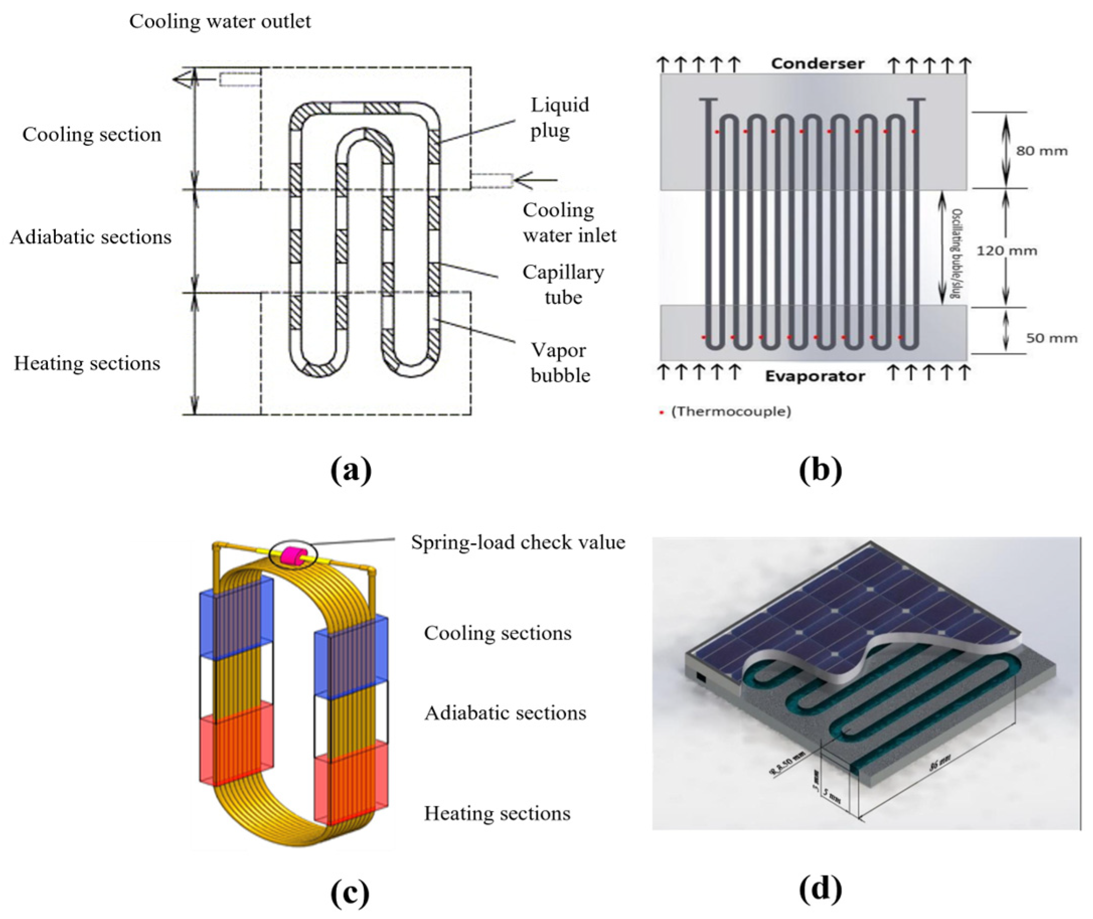
Figure 1. Types of PHPs. (a) Closed-loop pulsating heat pipes (CLPHPs) [1]; (b) open pulsating heat pipes (OPHPs) [2]; (c) pulsating heat pipe with check valve [3]; (d) flat-plate closed pulsating heat pipes (FPCPHPs) [4].
Inventions 09 00086 g001
Figure 2. Structure of different types of heat pipes. (a) Closed-loop pulsating heat pipes (CLPHPs) [1]; (b) loop heat pipes (LHPs) [10]; (c) separate heat pipes (SHPs) [11]; (d,e) gravity heat pipes (GHPs) [12,13].
Inventions 09 00086 g002
Figure 3. Development of injection flow (β = 70°, φ = 58%, Q = 8.7 W) [93].
Inventions 09 00086 g003
Figure 4. Details of heat pipe geometry [30].
Inventions 09 00086 g004
Figure 5. Configurations for PHPs: (a) parallel configuration; (b) series configuration [45].
Inventions 09 00086 g005
Figure 6. Contour map of maximum allowable heat flux [104].
Inventions 09 00086 g006
Figure 7. (a) Roughness of the surface inside a circular tube (Ra is arithmetic mean roughnes) [99]; (b) physical drawing (left) and size drawing (right) of sintered core; Do, Di, and ∆ are outer diameter, inner diameter, and sintering thickness, respectively [113]; (c) microchannel structure [114].
Inventions 09 00086 g007
Figure 8. (a) Thermal resistance of 3D-PHPs versus heating power with different filling ratios [117]; (b) thermal resistance of PHPs at 0° [113]; (c) thermal resistance of ternary mixture in horizontal direction [119]; (d) the relationship between the thermal resistance 3D-PHPs and input power under different inclination magnetic fields [57].
Inventions 09 00086 g008
Figure 9. Flow patterns one second before (left; slug pattern) and one second after fluid flow reactivation (right; annular pattern) [124].
Inventions 09 00086 g009
Figure 10. View of the FPPHPs’ flow pattern (left) and associated temperature (right) under microgravity conditions with water. Power input: 200 watts [22].
Inventions 09 00086 g010
Figure 11. Demonstrations of rotating PHPs. (a) Axial rotations and (b) radial rotations [126].
Inventions 09 00086 g011
Figure 12. RCLPHP experimental setup diagram [127].
Inventions 09 00086 g012
Figure 13. (a) Radial-rotating PHP experimental apparatus; (b) illustration of radial-rotating PHP [126].
Inventions 09 00086 g013
Figure 14. Heat transfer capacity of radial-rotating PHPs filled with (a) acetone and (b) DI water [126].
Inventions 09 00086 g014
Figure 15. Axial rotation PHP experimental apparatus [129].
Inventions 09 00086 g015
Figure 16. Correlation dimension of the temperature under different centrifugal accelerations: (a) acetone and (b) water. Lyapunov exponents of the evaporator temperature: (c) acetone and (d) water [129].
Inventions 09 00086 g016
Figure 17. The phenomenon of heating power of 50 W in different heating modes: (a) under continuous heating mode; (b) under pulsed heating mode [133].
Inventions 09 00086 g017
Figure 18. (a) Schematic diagram of the PHP mechanism; (b) spring–mass–damper model of PHPs [140].
Inventions 09 00086 g018
Figure 19. Structure of multi-turn pulsating heat pipes. (a) coordinate systems, and (b) numbering and finite-element discretization of fluid and vapor slugs [142].
Inventions 09 00086 g019
Figure 20. The physical model of film thickness in heating (a) and cooling sections (b) [147].
Inventions 09 00086 g020
Figure 21. Theoretical model of U-shaped pulsating heat pipes [92]. (a) The liquid–vapor interface at saturation temperature; (b) U-shaped mini-channel; (c) steady-state position of physical model.
Inventions 09 00086 g021
Figure 22. Comparison between visualization and simulation. A–F is the bubble appearing in the numerical simulation, and a–f is the bubble similar to A–F appearing in the experiment (in the same position). (a) Flow behavior with corrugated configuration is adopted in the evaporation section; (b) flow behavior with corrugated configuration is adopted in the adiabatic section; (c) flow behavior with corrugated configuration is adopted in the condensation section [165].
Inventions 09 00086 g022
Figure 23. Volume fraction cloud maps of the vapor phase in the PHPs with ia = 0 and ia = 3.5:5 and the same FR at 1400 s; ia is the ratio of the adiabatic section length to the total length of the PHPs [168].
Inventions 09 00086 g023
Figure 24. Volume fractions at steady state for GC1 (a), MGC1 (b), GC2 (c), and MGC2 (d) [166]. The evaporation sections of GC1 and MGC1 are traditional round elbows; the evaporation sections of GC2 and MGC2 are right-angled elbows. The heating mode of the evaporation section of GC1 and GC2 is a single heat source input, and the heating mode of the evaporation section of MGC1 and MGC2 is a multisource heat input.
Inventions 09 00086 g024
Figure 25. The vapor fraction contours evolution of FR = 40% (vapor bubbles are filled in red) as input power increases [167].
Inventions 09 00086 g025
Figure 26. Overall volume fraction cloud map of the vapor phase with different working fluids at a heating time of 3500 s [170].
Inventions 09 00086 g026
Figure 27. Liquid film around the vapor plugs in (a) evaporator, (b) adiabatic, and (c) condenser sections [172].
Inventions 09 00086 g027
Figure 28. Vapor slug’s coalescence and flow motion of bubble: (a) At the evaporator; (b) at the adiabatic surface [167].
Inventions 09 00086 g028
Figure 29. Local visualization device [173].
Inventions 09 00086 g029
Figure 30. Global visualization device. (a) Copper plate with machined engraved square channels forming U-turns [174]; (b) the glass pulsating heat pipes used for global visualization [175].
Inventions 09 00086 g030
Figure 31. IR temperature profiles for increasing thermal input power; the temperature scale is given alongside [177].
Inventions 09 00086 g031
Figure 32. Sequential flow images and temperature fields in bulk circulation mode for an asymmetric MPHE with a 60% filling ratio under vertical orientation [180]. (a) t = 0–110 ms; (b) t = 160–400 ms.
Inventions 09 00086 g032
Figure 33. PHPs for cooling rotating machinery. Radial rotation: (a) [127], (b) [126], and (d) [186]; axial rotation: (c) [129].
Inventions 09 00086 g033
Figure 34. Structure of PHPs in BTMS: (a) the⊥-shaped pulsating heat pipes [192]; (b) plug-in pulsating heat pipes [88]; (c) Coupling of 3D pulsating heat pipe and PCM [190].
Inventions 09 00086 g034
Figure 35. FPPHPs for high-power server CPU onsite cooling. (a) Dumbbell-shaped 3D-FPPHPs [7]; (b) PHPs locally heated in the central region and cooled on the other sides [194].
Inventions 09 00086 g035
Figure 36. Schematic of flat-plate PHPs with (a) symmetric channels and (b) asymmetric channels [195].
Inventions 09 00086 g036
Figure 37. Schematic for the design and operating principle of tandem dual-channel flat-plate PHPs [196].
Inventions 09 00086 g037
Figure 38. Schematic diagram and photograph of two silicon-based FPMPHPs: (a) CDC-FPMPHP; (b) UC-FPMPHP [197].
Inventions 09 00086 g038
Table 1. Single working fluids in references.
Single Working FluidsEffectRefs.
WaterLow boiling point, low dynamic viscosity, and low surface tension make them easy to start. High boiling point, high liquid specific heat, and high latent heat lead to greater anti-dry-out ability.[17,18,19,20,21,22]
Methanol[17,20,23,24]
Ethanol[25,26,27,28,29,30,31,32,33]
Acetone[7,23,24,33]
Hydrogen[36,37,38,39]
Helium[40,41,42,43,44,45,46]
Nitrogen[47,48,49,50,51,52,53]
Table 3. Mixed working fluids in references.
Mixed Working FluidsEffectsRefs.
Ethanol + WaterDelay of dry-out and heat transfer enhancement at low filling ratio[23,76,83,84,86,88]
Methanol + Water[23,83,90]
Acetone + Water[23,83,86]
Methanol + EthanolNo effective improvement in thermal performance[90]
Methanol + Acetone[85,90]
Acetone + EthanolImprovement in heat transfer at low filling ratio[85,90]
Table 4. Phenomena in status without motion of PHPs.
ConditionPhenomenonRefs.
HorizontalChallenges include working fluid reflux and modification of oscillation characteristics. Performance can be improved by micro-slot structure, magnetic field assistance, capillary structure, etc.[17,93,104,113,118,119,120]
Incline (from 0 to 90)Optimum inclination angle for heat transfer performance.[17,117]
VerticalInfluenced by gravity. Performance can be improved by capillary and proper adoption of the working fluid.[57,113,114,118]
Table 6. Phenomena in heating modes.
Heating ModePhenomenonRefs.
Pulsating heatingHeat transfer enhancement: withstand larger heat input.[132,133]
Auxiliary heatingRegression of local hot spot: promotion of start-up.[134]
Non-uniform heatingEnhancement of heat transfer performance.[39,122,131,135]
Disclaimer/Publisher’s Note: The statements, opinions and data contained in all publications are solely those of the individual author(s) and contributor(s) and not of MDPI and/or the editor(s). MDPI and/or the editor(s) disclaim responsibility for any injury to people or property resulting from any ideas, methods, instructions or products referred to in the content.