Abstract
Existing studies on infill patterns have tended to focus on pattern design rather than on geometric parameters. During this study, we propose a new controlling method focused specifically on the geometric parameters of infill patterns. The input parameters of this method can be used to create 3D printed objects with more lightweight interiors. The presented approach partitions a region of an object with user-specified distance inputs that are used to create infill pattern elements. Moreover, the proposed method will enable the generation of new design variations derived from a single pattern type with similar topologies and varying geometric parameters. The hexagonal pattern variations comprising regular and irregular elements have been presented. The variations of infill pattern design are useful for creating more lightweight and stronger 3D fabrications. The proposed approach is applicable for many different patterns, including linear pattern designs. The goal of this study is to devise a more cost-effective method of creating 3D-printed objects through the application of customizable infill patterns.
1. Introduction
The interior of 3D printed objects significantly impacts the printing process as well as the object’s physical characteristics. Depending on the end goal, 3D prints can be generated by using an interior that can either be solid, shell, or filled with geometrical patterns. 3D printed objects with an interior filled with geometrical patterns are considered to be more efficient in terms of material and printing time as compared to 3D prints with a solid interior. Moreover, interiors using geometrical patterns greatly improve the structural soundness of an object versus one created with a shell interior, which tend to collapse easily under an external load. The design and geometric parameters of infill patterns play a major role in the creation of 3D printed objects as they have a direct effect on their weight, quality, mechanical performance, handling characteristics, and production cost. Furthermore, the printing technology used can vary depending on pattern type and geometric parameters. During this study, we consider patterns printable via fused filament fabrication (FFF) [1] printing technology. We focus specifically on geometric parameters of infills, as our goal is to create a more lightweight interior for 3D fabrications. Currently, pattern optimization methods are used widely in open-access software packages [2,3,4]. Accompanying these methods, pattern size is controlled by user-specified volume percentages, where this percentage is dependent on the application goal. Higher volume percentages result in 3D fabrications that are more resistant to external loads, while lower volume percentages are used for more cost-effective 3D fabrications. It is important to note that pattern sizes are dependent on the volume percentage and the designed algorithm. Additionally, the region of an input object can affect the size of infills. Open-access software packages offer various types of infill patterns that can be applied to the interior of 3D printed fabrications. The above described method is useful for adjusting pattern size via volume percentage, it does not provide any information on the resulting geometric parameters, making it difficult for users to predetermine the final result. The method we propose addresses this by making a more precise structuring possible through user-specified geometric parameters. The presented method uses these parameters to control the size of resulting patterns and can be considered an efficient way to reduce material consumption by creating more lightweight 3D fabrication interiors with larger-sized pattern elements. Topology optimization methods are presented in various studies that aim to reduce material consumption by designing lightweight 3D printed objects. Topology optimization works by modifying the object’s external geometry in accordance with application requirements. To contrast, our method uses infill pattern parameters to generate the desired size of patterns—larger parameter values increase, and smaller parameter values decrease pattern size. Moreover, this approach enables the creation of new infill design variations derived from a single pattern-type with varying topology and geometric parameters. New design variants have different application purposes, with larger-sized variants used for applications requiring lighter interiors and smaller-sized variants used to strengthen 3D printed fabrications with thinner designs. Regarding this study, hexagonal patterns have been developed with different parameters. The region of an input object is partitioned by a user-specified distance that determines infill pattern size, in the presented methodology. The user-specified distance parameter must satisfy any specified preconditions to prevent errors. We experimented with presented infill patterns to evaluate the efficiency of our method. There are various uses for our method, including the creation of lightweight 3D fabrications. Our proposed method works for both hexagonal and linear patterns, which are used for the interior of 3D printed objects. The method creates lightweight 3D fabrications without interfering with their external geometry, therefore making it applicable for applications with topological sensitivity such as mechanical designs, industrial samples or 3D prints, which have stricter topological tolerances. The proposed approach does not require any complex or time-consuming steps or stages to create controllable infill patterns.
The specific contributions of our study are the following:
- We have developed a new method for controlling the geometric parameters of infill patterns. Our approach reduces the amount of printing materials consumed and results in a more lightweight interior for 3D printed fabrications.
- The method enables the user to specify the geometric parameters for infill patterns.
- Our method can create variations of infill patterns derived from a single pattern type. It also is applicable for different polygonal and linear type infill patterns.
The remainder of the paper is organized as follows: Section 2 includes related work where we review previous studies related to infill patterns of 3D fabrications and the subdivision methods. Section 3 describes the proposed method. Section 4 provides discussion of the experiment results, and conclusions are provided in Section 5.
2. Related Work
2.1. Subdivision
Chaikin [5] was the first to propose subdivision concepts for generating smooth curves. Most of the existing subdivision schemes for modelling and smoothing surfaces are based on Chaikin’s work. Generally, there are two groups of subdivision classes for approximating and interpolating subdivision, 1) approximating subdivision and 2) interpolating subdivision. Regarding approximating subdivision, we can refer to the schemes referenced by Catmull [6] and Clark, Doo and Sabin [7], subdivision schemes that recursively generate surfaces and extended bicubic and biquadratic B-splines. Peters et al. [8] proposed an algorithm that creates a new polyhedron by connecting every edge point from an initial polyhedron. Habib et al. [9] proposes a new method for edge and vertex insertion on four-directional C1 quadratic box spline surfaces.
Looking at interpolating subdivision, this describes several subdivision schemes which are referred to the interpolating subdivision group and have been proposed by various research teams. One widely used interpolation subdivision scheme is the “butterfly” algorithm proposed by Dyn et al. [10]. The algorithm is developed for a general triangulation of control points with a tension parameter. An improved version is proposed by Zorin [11]. The above described subdivision schemes have different purposes, the interpolating subdivisions mostly used for the controlling shape while the approximating schemes are used for smoothing curves. Regarding our study, we used subdivision schemes for generating the presented patterns with precise controllable geometric parameters.
2.2. Infill Patterns
3D printing technology fabricates high-resolution objects with less material consumed than traditional methods of manufacturing. The growth of open-access modelling tools [12,13,14,15] has made it easier to create digital 3D models with the desired geometrical complexity. It has been a widely used practice to fill the interior of 3D prints with selected infill patterns found on the settings of 3D printers or open-access software packages. Various types of infill patterns designed by different slicing tools are available. Various infill pattern designs have been investigated in many different studies, with the majority focusing on improving the physical properties or reducing the material consumption of 3D printed objects.
Stava et al. [16] presented a topology optimization method consisting of several stages of the hollowing, thickening, and strut insertion was presented. This topology optimization method greatly improved the structural soundness of 3D fabrications by producing visually similar objects with an input model, but with modifications in geometric parameters. Wang et al. [17] presented a method of skin frame structuring, where this approach generated lightweight 3D printed objects with less material consumption than required previously. The proposed structure comprised two key components: the struts, and the nodes that are connected to form the skin frame structure. According to the description of the method, it was created under the layer of an input model.
Lu et al. [18] developed a new algorithm that strengthens 3D printed objects with minimal material consumption. Their method created interior structures based on Voronoi diagrams, which determined the carving level for each Voronoi cell. Zhang et al. [19] proposed a novel interior structuring method with the medial axis. Researchers had been utilizing the medial axis to design lightweight structures for the interior of 3D printed objects, their framework made of several components united to create the media axis structures. The method was efficient in saving materials and improving the structural soundness of 3D printed objects. Researchers from another study proposed an adaptive void algorithm to hollow 3D fabrications [20]. A method of Voronoi foam structuring that generated 3D printed objects with controllable elastic properties was presented by Martinez et al. [21]. The method created rigid and flexible 3D fabrications. A study presented by Plessis employed complex patterns—biomimetic structures having irregular surface morphology, micro-scaled structures, and numerous composed holes [22]. Such complex structures required careful fabrication with feasible printing technology. Li et al. [23] presented a method of Gyroid structures which were developed to improve the physical properties of 3D printed models. The study included the details of the mechanical analysis that was done through cross-sectional analysis.
The presented study is related to our previous work [24] that was dedicated for multilevel interior design, where users could provide a number of columns and rows of infill patterns. The current study, based on our earlier work, is novel for specifying precisely the geometric parameters to control the size of infill patterns to design cost-effective 3D printed objects.
Researchers formulated their method as a goal-oriented balancing method [25]. An optimization algorithm was applied to create within the 3D object cavities that were filled partially with infill patterns. Only the required portions of 3D printed objects were filled with infill patterns to create self-supporting 3D fabrications. Indeed, not all 3D models are self-supporting, therefore some balancing optimization is required. To balance 3D fabrications, it is necessary to bring into equilibrium the shape, weight, and posture of 3D fabrications, as demonstrated by Prevost et al. [26]. Their proposed algorithm positioned 3D models precisely at the center of mass, reached through carving and deforming optimizations. These approaches also can be used for designing lightweight 3D-printed objects.
To contrast, Prevost [27] considered balancing 3D models using movable embedded masses where users could provide 3D models with the desired suspension, standing, and immersion characteristics. Their method determined suitable positions and sizes of a set of metallic capsules to result in multiple centers of mass. Hollowed cavities in the interior of 3D fabrications can reduce material consumption. Another method that also is applicable for balancing was proposed by Wu et al. [28], where researchers used adaptive rhombic infill patterns. Their method was efficient in designing the lightweight 3D fabrications with less material consumption. Using this method, researchers combined a balancing method with optimizing infill patterns to meet with user requirements.
Topology optimization methods can be considered an option that aims to reduce material consumption and improve the structural soundness of 3D fabrications. Topology optimization methods, however, interfere with the original geometry of 3D models to generate tailored 3D fabrications with the desired qualities. It is suitable mostly for creative designs rather than for industrial samples, mechanical models, or applications with stricter topological tolerances. Researchers created different variations of samples from a reference model to control its weight and improve its structural soundness [29]. The method produces visually similar 3D fabrications, albeit with modified geometric parameters.
The studies reviewed above experimented with various infill pattern designs. Methods were developed to create 3D fabrications with tailored qualities. During our study, we considered a precise approach to control the geometric parameters of infill patterns, as specified by users. Our method enables the fabrication of 3D printed objects with user-desired qualities. Specifically, we focused on designing 3D printed objects with a lightweight interior, achieved by taking control over the geometric parameters of infill patterns. The users can generate the larger-sized patterns for the cost-effectiveness of 3D fabrications while creating smaller-sized patterns for strengthening 3D fabrications. Furthermore, variations of a single pattern type can be created, which increases the number of visually similar infill patterns, thus increasing user choice.
3. Pattern Size Controlling Method
The previous section reviewed related papers studying infill patterns generated with different methods. Researchers, by experimenting with various infill pattern designs, intended to create 3D prints with reduced material consumption and improved structural soundness. The majority of studies considered the design of infill patterns. To contrast, we focus on controlling the geometric parameters of infill patterns. Our method modifies the pattern size according to user-supplied parameters and also can create different variations of a single pattern type that can be useful for managing material consumption and creating stronger and lighter-weight 3D printed objects. Our method begins with the generation of the bounding box of an input model based on the geometric parameters of the provided model. Next, the object region is partitioned with specific distance parameters provided by users. The size of infill patterns can be defined by the following equations:
where is the specified distance parameter; and are the area sides of an input object; the parameter divides sides of ; here determines a size of the pattern elements. must satisfy the following condition as and . Our proposed method enables users to specify precise values for parameters that impacts the pattern size. The presented method was built according to the system that is shown in Figure 1:

Figure 1.
The system pipeline of our method.
Employing the system shown above, we can create more cost-effective and lightweight 3D printed objects. It also can be used for strengthening purposes. Moreover, the method creates different variations from a single pattern type, as was done with the hexagonal patterns. New variations of hexagonal patterns made of regular and irregular pattern elements were generated.
3.1. Infill Patterns
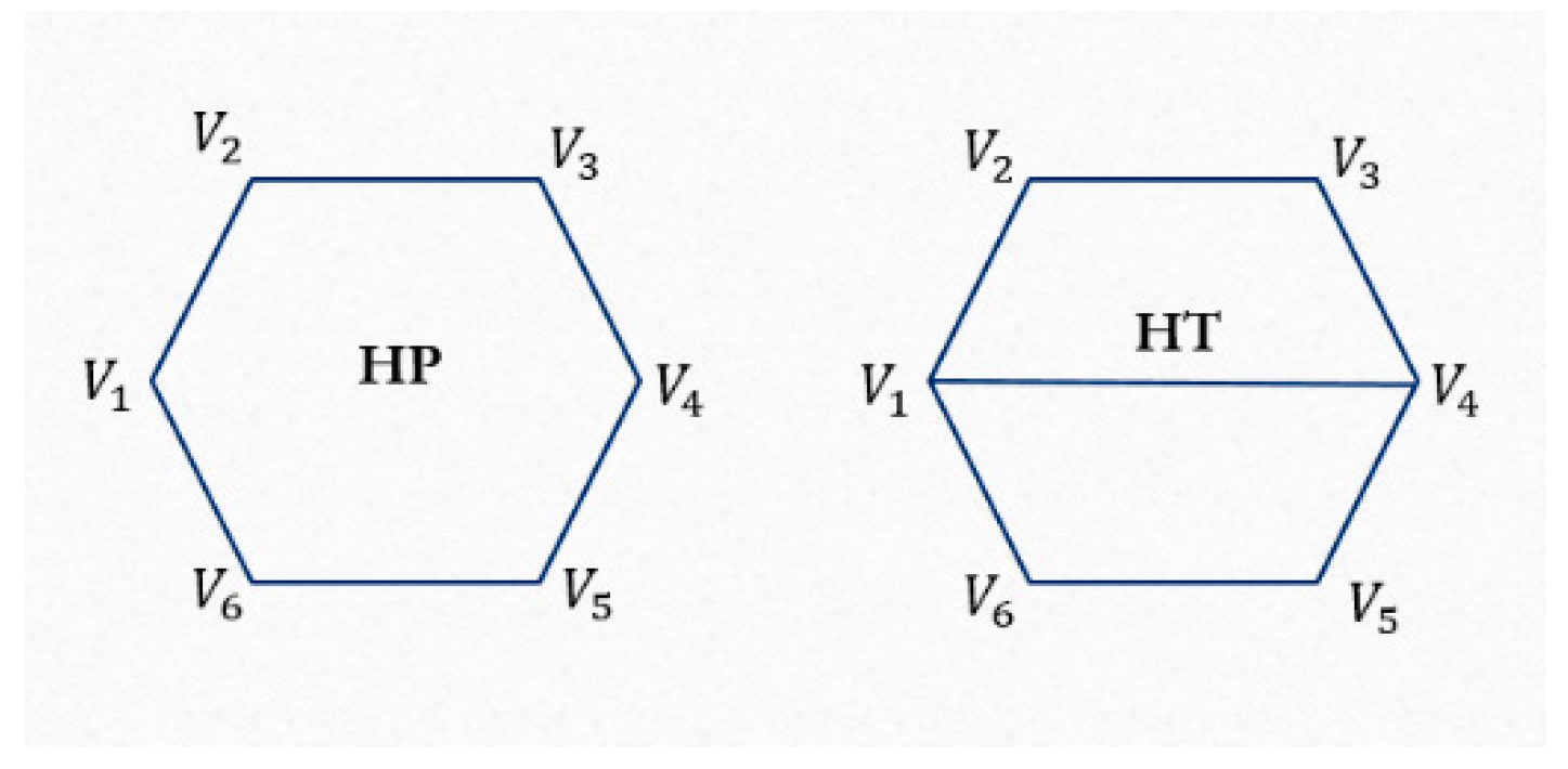
Presented are the hexagonal (HP) and the hexagonal trapezoid (HT) patterns, with some differences in their geometry. The geometric rules are the same for two patterns, but there is a difference between the connectivity of control points, therefore, the topological part is different for HP and HT patterns as it is shown from Figure 2.
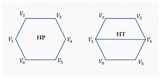
Figure 2.
Part for (left) HP pattern and (right) HT pattern.
We used a symmetric grid mesh to generate the presented infill patterns. Each element of the presented patterns is developed according to the following subdivision scheme:
where is the subdivision matrix and is the set of points, , .
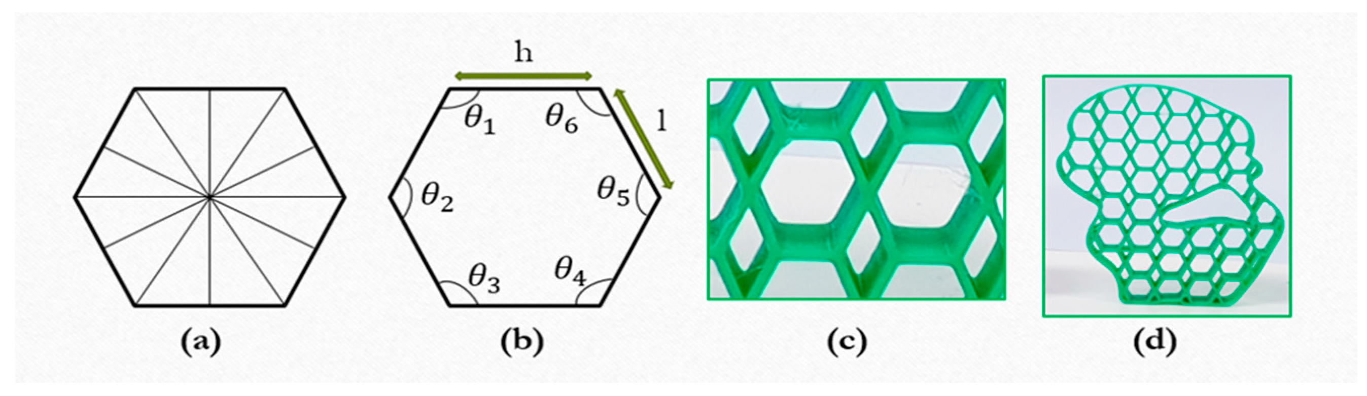
During this study, we consider two different cases for the geometric parameter optimization. Regarding the first case, has the same value for and . Hexagonal patterns with regular hexagonal elements are generated. Each element of the pattern has equal sides as . Since the pattern comprises regular hexagons, each element has all interior angles as with each angle within the hexagon as . A single element of the pattern has 6 symmetric lines, shown in Figure 3.

Figure 3.
The regular hexagonal element with (a) symmetrical lines and (b) geometric parameters including interior angles (c), and (d) outputs.
Considering the second case, the parameter is varied for and . Irregular pattern elements with sides are generated. When the element sides satisfy the following condition, then hexagonal elements are created with a larger width and differing interior angles. The geometrical parameters and outputs are shown in Figure 4.
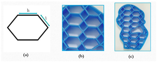
Figure 4.
The irregular hexagonal element with larger width, (a) element geometry (b,c) outputs.
Additionally, we considered another case when generated the elongated hexagon with non-equal horizontal and inclined sides as and with different interior angles. The differences between the regular hexagons and the irregular hexagons are observable with pictures. The elongated hexagons are shown in Figure 5.
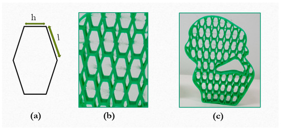
Figure 5.
The elongated hexagonal element, (a) element geometry (b,c) outputs.
Employing our geometric parameter controlling method, we can create different variations of hexagonal patterns, as shown in the above figures. The infill pattern parameters can be controlled to create lightweight interiors for 3D printed objects, as well as for designing the variations of a single pattern-type, as was shown with hexagonal patterns. Generally, we can create different variations of polygonal patterns derived from a single polygonal pattern type.
3.2. Linear Infill Pattern
The proposed method is applicable for polygonal as well as linear pattern types. As one might expect, linear infill patterns consist of line segments, while polygonal infill patterns are made of polygon elements. We can control the geometric parameters used to determine the distance between line segments for the linear patterns. The pattern was developed based on the following subdivision rules:
where is the subdivision; are the topological rules for linear patterns; and are the geometric rules.
The linear infill pattern is generated with the following subdivision matrix:
where is the subdivision matrix, is the set of points, where .
Regarding linear infill patterns, determines the distance between the line segments as is shown in Figure 6.

Figure 6.
The linear pattern with Sd = 0.4 cm.
Linear patterns can be created with different distances, as can be observed from Figure 7.
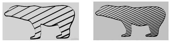
Figure 7.
Linear patterns with various distance parameters.
3.3. Pattern Size Regulation
The geometric parameters of patterns impact significantly the physical properties of 3D printed objects, such as quality and weight, as well as affecting the fabrication time. As mentioned earlier, we determined the pattern size by providing the parameter The pattern elements can be transformed according to application requirements. The enlargement and reduction transformations can be done by manipulating as follows:
where is the specified distance, is the transformation number, E is the enlargement parameter, and R is the reduction parameter.
4. Experiment Results
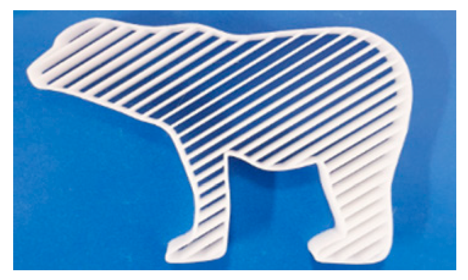
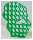
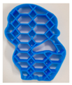
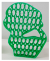
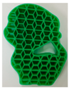
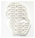
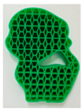
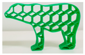
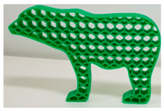
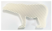
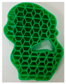
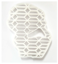
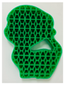
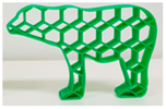
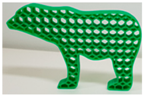
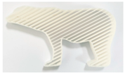
To evaluate our method we have created several 3D fabrications, as detailed in Table 1. We experimented with three different patterns where we carried out a weight comparison experiment to measure interior weight.

Table 1.
Weight of Models with Patterns.
The results of the experiment revealed the lightest one among bear models is the bear filled with hexagonal patterns weighing 14 grams. The model has larger infill patterns with , while satisfying the conditions and .
Regarding the second bear model weighing 23 grams, the specified parameter was , and it also satisfies the required conditions. We can conclude from the experiment that, to generate larger sized patterns, we need to provide larger values of parameter , while smaller sized patterns require smaller values of . The bear model filled with the linear pattern is heavier compared to other bear models because the geometric parameter of linear patterns was provided with the smaller value of . The presented approach is applicable for different patterns. The conducted experiment provides the confirmation of the efficiency of our method for designing the cost-effective 3D fabrications with controllable patterns.
Additionally, we conducted an experiment to compare the stress-sustainability of the samples, the experiment results are shown in Table 2.
Table 2.
Table Presenting Stress-Sustainability Results.
The compression test results showed that the samples with smaller-sized polygonal patterns are more stress-sustainable. The bear model with the smaller hexagonal pattern is more stress sustainable compared to the other bear models. The kitten model filled with the smaller pattern could resist 1617 N with a mass of 28 g. Our method can be used for strengthening 3D fabrications by controlling the geometric parameters of infill patterns.
Our models were printed with FDM 3D printer MakerBot Replicator 2 (MakerBot, New York, NY, USA) with a size of 285 × 153 × 155 mm. The wall thickness is 0.8mm for all samples. The used printing material is acrylonitrile butadiene styrene. The platform was developed using C++ language with Visual Studio 2015 and rendered with OpenGL API.
5. Conclusions
During this study, we proposed a geometric parameter controlling method to manage pattern sizes to create lighter and more cost-effective 3D printed objects. As the experiment has shown, larger patterns create lightweight 3D fabrications and consume less printing material. The proposed method is useful for designing 3D fabrications with cost-effective interior designs. Moreover, our method enables experimenting with different variations of infill patterns that can be derived from a single pattern type. The method is applicable to polygonal and linear infill pattern types. The study demonstrated and verified how geometric parameters of infill patterns influence the weight of 3D fabrications and their physical properties. Regarding future work, we plan to experiment with soft 3D-printed fabrications.
Conflicts of Interest
The authors declare no conflict of interest.
References
- Steuben, J.; van Bossuyt, D.L.; Turner, C. Design for Fused Filament Fabrication Additive Manufacturing. In Proceedings of the ASME 2015 International Design Engineering Technical Conferences and Computers and Information in Engineering Conference, Boston, MA, USA, 2–5 August 2015. [Google Scholar] [CrossRef]
- Ultimaker Cura. Available online: https://ultimaker.com/en/products/ultimaker-cura-software (accessed on 28 October 2019).
- KISSlicer. Available online: http://www.kisslicer.com/ (accessed on 28 October 2019).
- Slic3r. Available online: https://slic3r.org/ (accessed on 28 October 2019).
- Chaikin, G.M. An Algorithm for High Speed Curve Generation. Comput. Gr. Image Process. 1974, 3, 346–349. [Google Scholar] [CrossRef]
- Catmull, E.; Clark, J. Recursively generated B-spline surfaces on arbitrary topological meshes. Comput. Aided Des. 1978, 10, 350–355. [Google Scholar] [CrossRef]
- Doo, D.; Sabin, M. Behaviour of recursive division surfaces near extraordinary points. Comput. Aided Des. 1978, 10, 356–360. [Google Scholar] [CrossRef]
- Peters, J.; Reif, U. The simplest subdivision scheme for smoothing polyhedral. ACM Trans. Graph. 1997, 16, 420–431. [Google Scholar] [CrossRef]
- Habib, A.; Warren, J. Edge and vertex insertion for a class of C1 subdivision surfaces. Comput. Aided Geom. Des. 1999, 16, 223–247. [Google Scholar] [CrossRef]
- Dyn, N.; Levin, D.; Gregory, J.A. A butterfly subdivision scheme for surface interpolation with tension control. ACM Trans. Graph. 1990, 9, 160–169. [Google Scholar] [CrossRef]
- Zorin, D.; Schröder, P.; Sweldens, W. Interpolating subdivision for meshes with arbitrary topology. In Proceedings of the 23rd Annual Conference on Computer Graphics and Interactive Techniques; ACM: New York, NY, USA, 1996; pp. 189–192. [Google Scholar]
- Maya. Available online: https://www.autodesk.com/products/maya/overview (accessed on 28 October 2019).
- Rhinoceros. Available online: https://www.rhino3d.com/ (accessed on 28 October 2019).
- 3DS MAX. Available online: https://www.autodesk.com/products/3ds-max/overview (accessed on 28 October 2019).
- Blender. Available online: https://www.blender.org/ (accessed on 28 October 2019).
- Stava, O.; Vanek, J.; Benes, B.; Carr, N.; Měch, R. Stress relief: Improving structural strength of 3D printable objects. ACM Trans. Graph. 2012, 31, 48:1–48:11. [Google Scholar] [CrossRef]
- Wang, W.; Wang, T.Y.; Yang, Z.; Liu, L.; Tong, X.; Tong, W. Cost-effective printing of 3D objects with skin-frame structures. ACM Trans. Graph. 2013, 13, 177:1–177:10. [Google Scholar] [CrossRef]
- Lu, L.; Sharf, A.; Zhao, H.; Wei, Y.; Fan, Q.; Chen, X. Build-to-last: Strength to weight 3D printed objects. ACM Trans. Graph. 2014, 33, 97:1–97:10. [Google Scholar] [CrossRef]
- Zhang, X.; Xia, Y.; Wang, J.; Yang, Z.; Tu, C.; Wang, W. Medial axis tree-an internal supporting structure for 3D printing. Comput. Aided Geom. Des. 2015, 5, 149–162. [Google Scholar] [CrossRef]
- Sa, A.M. Adaptive Voids Primal and Dual Adaptive Cellular Structures for Additive Manufacturing. Vis. Comp. 2015, 31, 799–808. [Google Scholar]
- Martínez, J.; Dumas, J.; Lefebvre, S. Procedural voronoi foams for additive manufacturing. ACM Trans. Gr. 2016, 35, 1–4412. [Google Scholar] [CrossRef]
- du Plessis, A. Beautiful and Functional: A Review of Biomimetic Design in Additive Manufacturing. Addit. Manuf. 2019, 27, 408–427. [Google Scholar] [CrossRef]
- Li, D.; Dai, N.; Jiang, X.; Jiang, X.; Chen, X. Interior structural optimization based on the density-variable shape modeling of 3D printed objects. Int. J. Adv. Manuf. Technol. 2016, 83, 1627–1635. [Google Scholar] [CrossRef]
- Chynybekova, K.; Choi, S.M. Multilevel Design for the Interior of 3D Fabrications. Symmetry 2019, 11, 1029. [Google Scholar] [CrossRef]
- Christiansen, A.N.; Schmidt, R.; Bærentzen, J.A. Automatic balancing of 3D models. Comput. Aided Des. 2015, 58, 236–241. [Google Scholar] [CrossRef]
- Prevost, R.; Whiting, E.; Lefebvre, S.; Sorkine-Hornung, O. Make it stand: Balancing shapes for 3d fabrication. ACM Trans. Graph. 2013, 32, 81:1–81:10. [Google Scholar] [CrossRef]
- Prevost, R. Balancing 3D models with movable masses. In Proceedings of the Vision Modeling and Visualization, Bonn, Germany, 25–27 September 2017. [Google Scholar]
- Wu, J.; Wang, C.C.L.; Zhang, X.T.; Westermann, R. Self-supporting rhombic infill structures for additive manufacturing. Comput. Aided Des. 2016, 80, 32–42. [Google Scholar] [CrossRef]
- Dogan, K.M.; Suziki, H.; Gupinar, E. A generative sampling system for profile designs with shape constraints and user evaluation. Comput. Aided Des. 2019, 111, 93–112. [Google Scholar] [CrossRef]


© 2019 by the author. Licensee MDPI, Basel, Switzerland. This article is an open access article distributed under the terms and conditions of the Creative Commons Attribution (CC BY) license (http://creativecommons.org/licenses/by/4.0/).