Abstract
The performance of quadcopter frames, particularly in terms of weight and crash resistance, is significantly influenced by their structural design and manufacturing process. In this work, a methodology is proposed that integrates advanced principles of topology optimization (TO) and additive manufacturing (AM) techniques to optimize the frame structure for improved performance. First, an analysis is conducted to evaluate existing quadcopter frame configurations, identifying areas for improvement. Experimental evaluations of thrust and moment of motors are performed to assess the performance of the enhanced quadcopter frame, with a focus on advancing the design through computer-aided simulations of static structural analysis and impact tests. The TO technique is then employed to determine the optimal distribution of material within the frame, governed by constraints such as weight reduction and mechanical strength. The results demonstrate that the overall performance of a quadcopter frame is significantly improved by the proposed methodology, showcasing advancements in stability, weight reduction, and crashworthiness. The resulting optimized frame design is subsequently manufactured using AM methods, which offer advantages such as design flexibility and the ability to produce complex geometries. The findings of this study contribute to the field of quadcopter design and optimization by highlighting the synergies between TO and AM techniques. An avenue is offered for the development of lightweight and robust quadcopter frames, as the capabilities and performance of quadcopter systems are advanced. The insights gained from this research open up opportunities for further advancements in the design and manufacturing of UAVs.
1. Introduction
1.1. Scopic Overview
The rapid advancements in unmanned aircraft, commonly known as drones or Unmanned Aerial Vehicles (UAVs), have revolutionized the way we perceive and interact with the skies. From military operations to commercial applications like package delivery, drones have become versatile tools with a wide range of capabilities. Among these UAVs, quadcopters stand out as a modern and agile type of rotorcraft, propelled by four quick-turning rotors. By adjusting the speed of the rotor discs, pilots can precisely control the quadcopter’s movements using remote control transmitters. Quadcopters are often compact and lightweight, making them suitable for various applications such as aerial photography with limited payload capacity and flight duration of around 20–30 min. Nevertheless, UAVs have applications in diverse fields with varying budget requirements, including civic surveillance, navigation, military operations [1], and mechanical architecture [2]. However, the utilization of UAVs raises concerns about their impact on public safety. A recent study identified autonomy as a promising research area to enhance aeronautics [3].
While recent research in advanced UAV technologies mainly focuses on fault diagnosis [4,5,6,7,8,9,10,11], recent research assembled a quadcopter with limited financial resources to conduct surveillance in [12]. In contemporary professional settings, individuals engaged in drone piloting or academic research predominantly engage in the construction of drones by utilizing commercially accessible frames and structural designs. The cost associated with financial measurements can be relatively high. Therefore, the utilization of a lightweight frame that can be easily produced through additive manufacturing (AM) is of significant importance.
The paper is organized as follows: Section 2 explores frame design and fabrication. The experimental approach in Section 3 covers motor and propeller assembly, thrust and moment calculations. Section 4 presents testing and comparison results, including topology optimization (TO). The utilization of AM for fabricating optimized quadcopter frames is discussed in Section 5. Section 6 elaborates on the study’s limitations. Finally, the conclusion summarizes the key findings of the study, as outlined in Section 7.
1.2. Related Work
Satra et al. [13] improved quadcopter frame designs using carbon fiber tubes and 3D printed connectors, optimizing balance and strength through ANSYS software 15.0. Parandha and Li [14] used ABS-PC and fiberglass for an X-shaped frame, ensuring structural integrity with SolidWorks simulations and achieving a safety factor of 2.5. Gardner et al. [15] enhanced quadcopter frames using continuous carbon nanotube (CNT) yarns and Ultem, overcoming material merging challenges while optimizing mechanical and electrical properties with a dual-nozzle 3D printer. Shenoy et al. [16] developed a multimodal quadcopter for air, water, and land, incorporating unique sub-assemblies and a retractable robotic arm. Gandhi and Ghosal [17] designed an H-shaped quadcopter for low-cost military surveillance, optimizing for lightweight and control at high altitudes. Radharamanan [18] combined Acrylonitrile Butadiene Styrene (ABS) and Polylactic Acid (PLA) in a drone, focusing on dimensional accuracy and surface roughness with dual 3D printing. Natarajan et al. [19] significantly reduced robot weights by 54.4% and developed a walking algorithm in a topology-optimized multi-modal robot using Autodesk Fusion 360. Nonetheless, Farah et al. [20] assessed various properties of quadcopters, including the stability and recyclability of PLA and other polymers. Kuantama et al. [21] designed a lightweight frame analyzed for stability with Finite Element Analysis, noting impacts on thrust efficiency. Bhandari et al. [22] used Creo 2.0 and ANSYS for modeling and vibration analysis, tailoring a frame for heavy transportation. Sheng et al. [23] developed a 7 kg amphibious vehicle, evaluated through FEA for structural integrity and tested across multiple terrains. Zhang et al. [24] created a three-layered sandwiched quadcopter frame with optimized carbon fiber layers, improving endurance to 29 min and payload to 700 g. Chan et al. [25] designed and tested a 3D-printed quadcopter frame, analyzing stress and aerodynamics, comparable to the DJI F450. Vepa and Sagar [26] optimized a monocoque frame using a genetic algorithm, achieving a cost-effective and lightweight design through transient simulations. Lastly, Ali and Jaber [27] analyzed the performance differences between cross and quadcopter configurations, highlighting stability issues in the plus configuration during pitch and roll maneuvers. A detailed comparative Table 1 summarizing the key methodologies from related selected studies is presented below.

Table 1.
Selected studies and their relativity to the current approach.
1.3. Aim, Objectives, and Contribution
This research aims to enhance the design and manufacturing of quadcopter frames by addressing the current limitations found in comparative analysis and the utilization of advanced technologies. Our specific objectives include the following:
- Investigating quadcopter frame specifications with a focus on mechanical strength, weight, and structural integrity to improve performance and durability.
- Implementing 3D printing technology and topology optimization (TO) to develop lightweight and robust quadcopter frames that meet the demanding needs of UAV applications.
- Conducting experimental tests to accurately calculate the moment of inertia of the motor for the optimized quadcopter frame, ensuring reliable performance under operational conditions.
2. Frame Design and Fabrication
Commercial drones, particularly quadcopters, dominate the market, but other types with varying motor numbers and frame designs also exist. The drone’s properties, including stability, flying duration, and speed, heavily depend on these factors. Frames are categorized by their motor-to-motor distance, with micro frames being less than 150 mm and mini frames exceeding 150 mm. Unconventional frames like hexacopters or tricopters use the largest motor-to-motor distance for measurement. Designing a quadcopter frame entails creating a lightweight yet rigid structure capable of carrying components, sensors, and rotors. SolidWorks was utilized to develop a 3D model, and Finite Element Analysis (FEA) determined stress and weight. Computer-Aided Design facilitates design development, modification, analysis, and optimization.
2.1. Frame Types
The X frame is the most popular quadcopter frame, with motors located at the arm tips and electronics mounted at the junction. Motors in the X-frame version work together in movement and direction, where motors 2 and 3 drive the drone forward, motors 1 and 4 drive it backward, motors 1 and 2 steer it left, and motors 3 and 4 steer it right. This distribution of the steering mechanism provides strength and efficiency, as impacts from crashes in the X or Y direction are absorbed by two arms instead of one. On the other hand, the plus frame is a rotated X frame, with each motor responsible for a specific direction. Flight maneuverability and stability are generally contradictory and cannot be improved simultaneously, but logically, flight maneuverability can be improved by improving structural stability. While the plus frame offers maneuverability and control advantages, it is more vulnerable to crashes, as a single arm absorbs the impact. The H frame, with parallel arms housing the motors and a centerpiece for electronics, provides more space for electronics compared to other frames but is less stable for stunts and racing. However, the H frame is known for its durability and resistance to breakage in crashes. Despite its awkward configuration, the H frame has its advantages, although it has lost popularity due to its bulkiness. Figure 1 displays the three frame configurations of quadcopter UAVs, specifically Figure 1a. Figure 1b, on the other hand, illustrates the SolidWorks-based designs of the adopted three frames regardless of the dimensions.
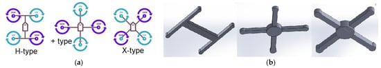
Figure 1.
Frame types: (a) general quadcopter frame types; (b) CAD-produced frames.
2.2. Aerodynamic Behavior Assessment
This section aims to analyze the aerodynamic behavior of each frame. Usually, the quadcopter is exposed to an undesirable drag force at different movements. If the drag force increases, it will cause imbalance and rapid battery depletion. This force value depends on the effective frontal area, velocity, and air density, as in the following [40]:
where is the translate velocity, and is the drag force constant, which depends on the effective frontal area of the quadcopter and air density:
where is the air density in kg⁄m3, is the aerodynamic drag coefficient and is the effective frontal area that faces the flowing air in m2. For this reason, is considered the measure of the frame’s efficiency from the aerodynamics perspective. The smaller the value, the more efficient the aerodynamic frame is. In order to test which of the above-mentioned frames is aerodynamically more efficient, default shapes (X, +, and H) of constant volume and weight for each frame were designed. Then, the value of the for each of them was obtained for the different movements in the X, Y, and Z directions. The size of the designed quadcopter frame is 40 cm, and its weight is 400 g. for each quadcopter frame was calculated directly using the SolidWorks Flow Simulator. Drag force constants in the Z direction are the same for each configuration because they have equal effective areas. When the quadcopter moves in the horizontal direction (X or Y), it tilts at a certain angle (pitch or roll), respectively. Here, the movement at an angle of 30 degrees and a speed of 10 m per second for all cases and frames is considered in the calculations. Its movement in the X and Y direction will be the same in both cross and plus frames. In contrast, the H frame will move differently in the two directions because of the unequal effective area that causes dissimilar isosurfaces (airflow distribution in space) and flow trajectories at the same X or Y speed. Figure 2 below shows the airflow on all frames in the X and Y directions. The results are shown in Table 2 below according to the frame and direction of movement. Figure 2 depicts the lines of interlocking and air penetration to the frame’s edges, representing the flow streamline trajectories. The dark, transparent shapes also show the disorder and turbulence resulting from the pressure difference in the air distribution between the nose of the quadcopter and the rear, called distribution air in the space. The reverse air velocity is generated from the pressure vacuum wherever the quadcopter is heading in the back of it. It results in a negative velocity, as in the figures below, where the blue color of the scale indicates it, and the greater it is, an indication of more energy consumption and great drag force. Figure 2 shows that the cross frame is generating less reverse speed due to the fact that the parts of the frame collide at an angle of 45 with the air, unlike the other frames.
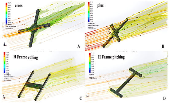
Figure 2.
Airflow trajectories on different quadcopter different frames.
Table 2.
The obtained drag force constant of horizontal motions for different frames.
Table 3 shows the best features of the same-size quadcopter frame. An X-frame can operate with the best and most accurate control system because the arms guarantee stability from the centralized center of gravity. X-quadcopters comfortably perform stunts, rolls, pitches, and flips. They are also characterized by a symmetrical pitch and roll axis and less drag force. Furthermore, it should be noted that these frames possess a relatively low weight in comparison to H-frames. Consequently, this characteristic renders them highly suitable for employment in FPV racing scenarios, as their lightweight nature contributes to enhanced flexibility and predictability in terms of their maneuverability. H-frames may be conspicuous to novice participants in the field of First-Person View (FPV) racing; however, X-frames have been widely regarded as the optimal drone frame for racing purposes. Additional commonly used frames in this context encompass the hybrid X, wide, and stretched X frames that have been adapted to cater to diverse capabilities and enhance overall performance. One drawback associated with racing drones that lack popularity is their reliance on specialized motors and certain components. The task of obtaining replacements and spare parts can present significant challenges. The X frame was chosen for this study based on a comprehensive evaluation.
Table 3.
Quadcopter frames comparison summary.
3. Experimental Approach
3.1. Motor and Propeller Assembly
The inclusion of motor and propeller data is of utmost importance in the design process of practical implementations of UAVs that utilize rotorcraft technology, such as quadcopters. When selecting the appropriate motor and propeller for a quadcopter, it is crucial to take into account the dimensions of the vehicle as well as the battery’s longevity. This consideration ensures that the quadcopter is capable of achieving the desired duration of hover and maneuverability. Hence, it is necessary to obtain certain data pertaining to the motor and propeller, such as thrust, motor speed, voltage, and current consumption [41].
3.1.1. Thrust Calculation
In this research, to measure the thrust force generated by the propellers, a test rig equipped with a digital weight scale for thrust measurement, some sensors to measure voltage and current consumption, and a tachometer for rotation speed measurement were designed and fabricated. A schematic diagram of this rig is shown in Figure 3; the test is conducted by supplying the motor with a pulse width modulation (PWM) signal. The scale has been calibrated by known accurate weights. Statically applying the formula for torque acting (or) moment of the couple:
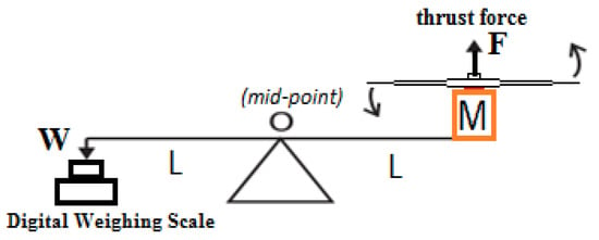
Figure 3.
Thrust and speed measurement device scheme.
The motor used is A2212/3T 1800 KV with a propeller size of 6045 L, and the power supply used is 11 Volt and 0–20 Ahm, which is supplied on ESC (Readytosky 40A). The PWM controls the motor speed in the rig, namely Cyclic/Collective Pitch Mixing (CCPM) Servo Tester, as shown in Figure 4.
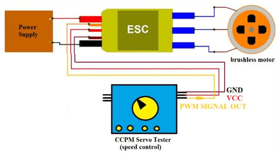
Figure 4.
Brushless motor speed control system [42].
The Servo Tester used in the study’s setup is instrumental in controlling the motor speed and the pitch of the propellers simultaneously, allowing for precise adjustments to the quadcopter’s flight dynamics. This method integrates the collective (throttle) and cyclic (pitch and roll) controls into a single input, which simplifies the mechanical complexity and enhances the responsiveness of the quadcopter. By modulating the pulse width modulation (PWM) signal provided to the motor’s electronic speed controller (ESC), the CCPM Servo Tester ensures that the motor’s speed and the propeller’s pitch are adjusted in real time to achieve optimal performance under varying flight conditions. The ESC, specifically the Readytosky 40A model used in our experimental setup, plays a pivotal role in regulating motor speed. It handles inputs from the CCPM system and adjusts the power supplied to the motor to control speeds up to the maximum capability of 10,000 rpm. This high-speed output is crucial for achieving the desired thrust and maneuverability of the quadcopter. The ESC also ensures that these high speeds are safely managed by providing precise control over the electrical currents and voltages supplied to the motor, thereby protecting the motor and propeller assembly from electrical and thermal overload. The current design considers the potential high-speed outputs of the ESC to determine the best performance configurations without compromising the safety and efficiency of the quadcopter.
In the beginning, a balancing mass is added on the BC side to balance the masses of the ESC motor and the propeller on the AC side so that the rotating beam is balanced around the journal-bearing shaft (point C), as can be seen in Figure 5. After calibrating ESC with CCPM ranges, the CCPM knob is increased gradually, indicating a proportional increase in rotation speed (RPM), current consumption (Ahm), and weight (Kg).
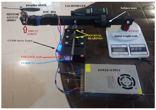
Figure 5.
Measurement system of thrust force, speed, and power. A represents the arm of the drone, B represents the normal bar, and C represents the point of acquisition for the tachometer.
The motor used can rotate at full speed at a voltage of 11 volts, according to the theoretical equation (without a propeller):
It was experimentally found that the maximum speed of the used motor with a 6045 L propeller was 13,300 RPM with a current consumption of 13.2 Ahm. This speed provides a thrust force of 579 g. In fact, running at this high speed for a short time was accompanied by a slight increase in the temperature of both the motor and the ESC. However, in this research, this speed will not be reached because of the proposed design of the quadcopter with a size and equipment that does not exceed 1 kg or less. Therefore, the results were taken for a lifting force slightly exceeding the weight of the quadcopter (285 g at a speed of 9380 revolutions per minute with a consumed current of 5 Amps for one motor). The results are shown in Figure 6a–c. It can be noted from the readings in the previous table that energy consumption increases with speed or thrust force.
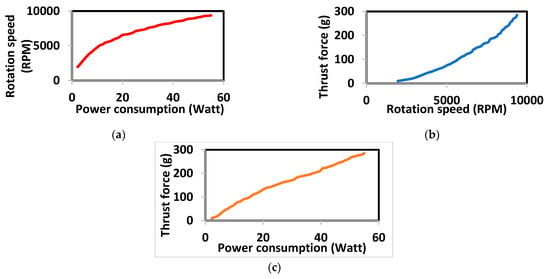
Figure 6.
Experimental evaluation: (a) power consumption per speed; (b) thrust force per speed; (c) thrust force per power consumption.
The propeller force is linear, and it is strictly proportional to the speed of the rotors. A single rotor’s thrust force is proportional to the square speed of the rotor [13,38], as shown in Equation (6):
where is the thrust force in N, is the aerodynamic force constant (N·s2), which depends on the motor and propeller specification, rotating speed in . By solving the above equation with the data shown in Table 3, the following will be obtained, which is needed later in this work: .
3.1.2. Moment Calculation
The Hub Torque of the propellers is responsible for yaw rotation in the quadcopter; its effect is defined as follows [13]:
where is the aerodynamic moment, is the aerodynamic moment constant, which depends on the motor and propeller specifications. can be computed experimentally by measuring rotation speed vs. the generated torque ( weight × arm length), as shown below in Figure 7. Then, Equation (7) is applied to find = 7.49356 × 10⁻⁸ N·m·s2.
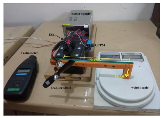
Figure 7.
The designed test rig to find the aerodynamic moment constant.
3.2. Frame Design Principles
The quadcopter frame is a rigid body exposed to various forms of dynamic and static stresses resulting from the aircraft’s weight, lifting forces, and vibrations resulting from the motors and propellers. Additionally, the frame is always subjected to fracture when the quadcopter falls, even if it is at a small height, so it is necessary to strengthen the structure to ensure lightweight and reasonable strength. The quadcopter frame plays a crucial role in the overall functionality and performance of a quadcopter. Nevertheless, it should be noted that there exists a wide variety of quadcopter frame sizes, and there is no universally applicable guideline for determining the appropriate frame size. However, it is worth mentioning that the most frequently encountered frame sizes typically fall within the range of 180 mm to 800 mm. Various quadcopter frames are specifically engineered to cater to different styles of quadcopters, including FPV, sports racing, cameras, mini, and others. The frame size of a quadcopter is the distance from opposite corner motors, which is called the wheelbase. So, if the distance is measured from the front left motor to the right back motor, that distance (in millimeters) is the frame size. Quadcopter frames are classified based on their wheelbase [13]. In this paper, the work is focused on a size of 400 mm. The frame’s weight must not exceed 500 g in addition to the weights of the other elements. The weight of the electronic components that are proposed to be used in this research are listed in Table 4:
Table 4.
Weights of the quadcopter electronic components.
The total weight of the quadcopter and its components is 787 g. To maintain stable hover, each of the four motors must produce a thrust force of approximately 200 g (787/4). Referring to Figure 7 for specific performance data at this thrust level, these values are crucial for optimizing the design using TO to achieve the lightest and strongest structure.
4. Testing and Comparison Results and Discussion
4.1. Topology Optimization
TO is a technique that allows for increasingly efficient designs, and its objective is to maximize the performance of mechanical systems or structures in various fields [43,44,45]. Attempts to use TO for components created using traditional processes such as casting, forging, injection molding, CNC machining, and the like failed owing to current production limits regarding geometrical complexity. Currently, AM methods, such as 3D printers, enable the manufacture of more complicated forms, which, in theory, will lead to increased performance when the TO idea is used. In this section, the TO is applied on the quadcopter frame to save the frame rigidity as the first priority, reduce the weight as much as possible while maintaining the maximum possible stiffness of the frame, and keep the original shape of the frame. The default shape of the cross-quadcopter is a square base with four crossed arms. The square base area provides a place to install electronic parts. SolidWorks 3D was used to draw the default frame of the cross-quadcopter configuration; all dimensions of the designed quadcopter in (Cm) are shown in Figure 8a. The frame was analyzed using SolidWorks Simulation; the analyses included static, dynamic, and impact, where vibration mods and greatest stress and deflection were assessed. All parameters necessary for the analysis of the applied forces and properties of the material of PLA were originally found there. Thrust force is generated on the base from the top side of the motors upward; the base is fixed on the bottom side, as shown in Figure 8b.
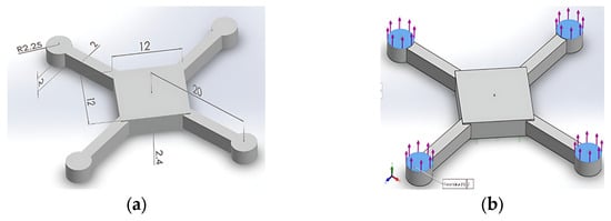
Figure 8.
Quadcopter frame: (a) default shape of the cross-quadcopter; (b) thrust forces positions.
The optimization algorithm produces the component shape with the greatest rigidity, taking into account the quantity of mass subtracted from the initial maximal design space. Table 5 highlights the utilized parameters while modeling the SolidWorks program. When determining the Best Stiffness-to-Weight ratio, the algorithm attempts to minimize the global compliance of the model, which is a measure of the overall flexibility (inverse of stiffness). Compliance is defined by the totality of all elements’ strain energies. It can be seen in Figure 9a that some parts and spots in the default frame have been removed, as the TO analysis calculates the stress at every point in the body and then removes the mass subjected to a small stress or not at all. This reduces the weight of the quadcopter frame and preserves its strength. The purple and blue zones in the body of the frame can be removed because the stress on them is nonexistent or very little compared to other areas of the body. The new weight of the frame is 400 g, so the weight loss was as follows: 797 − 400 = 397 g removed. This means about 50% of the frame weight is gone. Exporting the mesh as a solid or a surface part can convert it to an STL file (or some other file format of choice) to be later used in manufacturing utilizing the 3D printer, as shown in Figure 9b.
Table 5.
TO parameters and specifications.
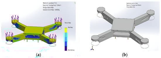
Figure 9.
Quadcopter optimized frame: (a) reduced mass and saving stiffness by TO; (b) optimized frame as smoothed solid part.
4.2. Static Structural Analysis
Static analysis was used to show the maximum stress (N/m2), deformation (mm), and strain. The deformation is referred to as URES (U Resultant), which is how the SolidWorks programs refer to a distinct deformation. Figure 10 shows all of the three terms simulation static study results; the deformation scale is 1267.92, which is required by the software to enlarge the deformations that happened to make them higher than the real ones. In this chapter, in all the analysis figures presented, the red color represents the locations of the highest stress, strain, deformation, and amplitude. On the other hand, the new static results show a slight increase in the maximum stress, displacement and strain values, as shown in Figure 11 below.
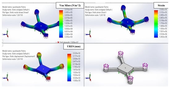
Figure 10.
Static analysis results.
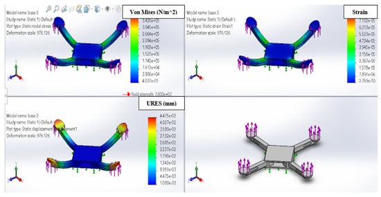
Figure 11.
New optimized frame static results.
4.3. Impact Test
The drop test evaluates the effect of the impact of a part or an assembly with a rigid or flexible planar surface as dropping an object on the floor is a typical application. The software calculates impact and gravity loads automatically [46,47]. The Drop Test Setup Property Manager sets parameters for a drop test study, setting the height from which the body is dropped from rest (20 m). This is the distance that the body has to travel in the direction of gravity to hit the rigid plane, setting the reference entity to determine the directions of the gravity drop. The most anticipated quadcopter crash in the most likely directions and angles of the quadcopter fall is when it drops vertically with variant degrees on the number of arms. Therefore, this is the presented impact test for both normal and optimized frames. Herewith, the fall load in the previous test will be distributed equally across two arms, and the ground reaction force will be at an angle of 45 on each arm. The stress–strain will certainly be less than in the previous test. The deformation will be higher as the force acting has a transverse effect, not a longitudinal one. Figure 12 depicts the deformation of the standard frame impact. With the same conditions as the previous fall of the frame at the height of 20 m, the results of the fall analysis are presented in Figure 13. Logically, an increase in stress is accompanied by an increase in both strain and deformation; according to Hooke’s law [48], it has been observed a very slight increase in the mechanical parameters (stress, deformation, and strain) in the results.
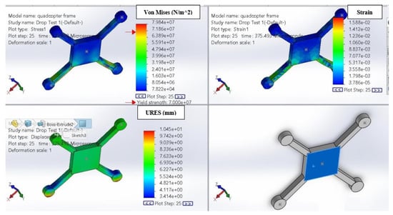
Figure 12.
Drop vertically with 45 degrees on two arms.
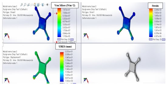
Figure 13.
A new optimized frame dropped vertically on two arms.
4.4. Comparison Aspects
Table 6 summarizes the difference in the results between the two structures before and after the TO process. The values in the left column of the table cells refer to the frame analysis results before TO, and the values in the right columns refer to the new frame analysis results after TO.
Table 6.
Quadcopter frame and new optimized one comparison results.
In the static analysis of the two cases, before and after optimizing the frame, the safety factor was very large in the first case (before the optimization), 21.1, and the new one was 18.4, indicating high safety in both cases, according to Equation (8) of the safety factor calculation [48]:
If objects fall from high heights, no matter how strong, they will be subject to deformation and fracture. Therefore, a study of the effect of the new and old frames being dropped was conducted with a fall from a high height of about 20 m. It was found that the stresses generated as a result of this fall are very high, and in some cases, the stress exceeds the yield of the PLA material. This means that the safety factor may be close to one or smaller than it, which is very normal due to the high considered altitude. However, when the values of the generated stresses are observed, it can be seen that they are very close, as the stresses of the improved design were slightly higher than those of the initial frame. Finally, legs were added to the lightweight quadcopter; hence, the optimized frame is ready to be fabricated by the 3D printer using the PLA material filament, as shown in Figure 14.
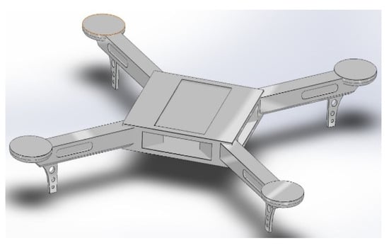
Figure 14.
The final frame design ready to print.
5. Additive Manufacturing
AM technologies are becoming increasingly useful strategies for different purposes in many industrial fields [49,50,51,52,53]. Among the most outstanding applications are part prototyping and single-part to small batch production. They relatively reduce manufacturing times and investment costs, reduce material consumption, and produce innovative and efficient shapes. Under these circumstances, the inspiration given by TO tools can lead to feasible industrial parts with fewer constraints compared to traditional manufacturing processes. This work presents the development and results obtained using TO and design for AM technology on a previously analyzed quadcopter frame. The final design reduces weight via savings in terms of the default frame’s mechanical properties. The frame’s mass before the optimization was 797 g, as calculated before. The same magnitude of thrust forces was exerted on the frame in the case of TO analysis.
The spectrum of manufacturing techniques beyond AM highlights the strengths and adaptability of traditional methods. Techniques such as CNC machining and injection molding are pivotal in UAV frame production as they offer unique advantages in terms of material selection, structural integrity, and cost-efficiency at scale [54,55]. CNC machining, for instance, allows for the use of a wide range of aerospace-grade materials like metals and high-density polymers, providing superior strength-to-weight ratios that are crucial for UAV performance. Meanwhile, injection molding, known for its unparalleled efficiency in mass production, presents a cost-effective solution for high-volume manufacturing, significantly reducing the unit cost of production. These traditional methodologies, when chosen appropriately based on design complexity, production volume, and material requirements, can sometimes outperform AM in terms of production speed and cost-effectiveness. This comparative analysis underscores the importance of selecting the most suitable manufacturing method to take into account the specific requirements and constraints of UAV frame design by achieving an optimal balance between performance, cost, and production efficiency.
Three-dimensional printing software tools are applications that aid in the execution of the 3D printing process. Because slicers take a CAD model, slice it into layers, and convert the model to G-code, they are the simplest methods to move from a 3D model to a printed object. The slicer program also adds 3D printer parameters to the G-code, such as temperature, layer height, print speed, density, and so on. This G-code can be read by the 3D printer, which will then build the model layer by layer according to the instructions in the G-code. There are many applications that use this software, the most prominent of which is Ultimaker Cura. Cura can be used with almost any 3D printer because it is an open-source slicer. The program is ideal for beginners because it is intuitive, fast, and easy to use. More advanced users can access a further 2000 settings to refine their prints. Figure 15a shows the interface of the Cura program in which the quadcopter appears, consisting of five parts, a main middle base, and four arms. In this program, it is possible to control the printing density, speed, temperature of the printing bed and the nozzle so that it matches the ambient temperature and the material used for printing. This helps overcome the low bed temperature that causes pieces to come off during printing if the printer is in a cold environment (bad adhesion). Additionally, using incompatible nozzle temperatures with the material’s melting point leads to clogging and damage to the filament ducts, including damage to the nozzle. The 3D printer used in this research is the FDM Creality brand Max 10, a large-size printer with dimensions of 45 × 45 × 50 (x, y, z) cms, as shown in Figure 15b.
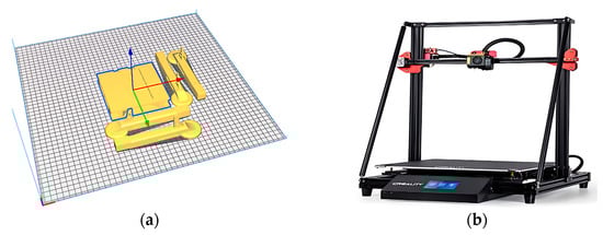
Figure 15.
AM: (a) quadcopter solid parts in Ultimaker Cura program interface; (b) 3D-printer FDM Creality Max 10.
After 16 h and a few minutes, the solid models were transformed into physical objects with dimensions and weights that were 100% accurate. The printed sample is completely clear and complete. After the samples were extracted from the platform, the five parts were assembled together. Each centimeter arm was inserted into the main base and secured using a 3 mm plastic screw. Additionally, Table 7 shows the commonly employed materials for quadcopter frame 3D printing, each with its specifications, in terms of PLA, ABS, and Polyethylene Terephthalate Glycol (PETG) modifications. The cost tolerances of printing the final outcome using the previously mentioned 3D printer are listed in Table 8, where the cost is cut in more than half. Figure 16 shows the complete printed frame utilizing the PLA material. In the Iraqi market, where PLA is more readily available and significantly cheaper compared to PETG, PLA has been chosen for printing quadcopter frames. Despite PETG being recognized as the superior option due to its balance of strength and durability, PLA’s affordability and widespread availability make it a practical choice for many enthusiasts and hobbyists in current experiments.
Table 7.
Specification of different commonly employed materials for the purposes 3D printing quadcopter frames.
Table 8.
Weight-Cost comparative analysis.
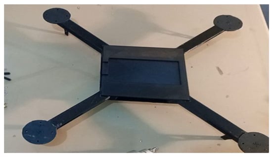
Figure 16.
Assembled quadcopter frame.
6. Limitations
In the current methodology, while direct measurements of the frame’s tensile strength post-optimization were not conducted, the use of a PLA material with a known tensile strength of approximately 50 MPa and a density of 1.24 g/cm3 allows for an inferred analysis of the improvements in the strength-to-weight ratio. The significant reduction in frame weight from 797 g to 400 g, as outlined previously in Section 5, demonstrates the efficiency of TO in material usage also suggests an enhancement in the overall strength-to-weight ratio. This inference is based on maintaining a consistent material tensile strength across the design, thereby improving the quadcopter’s performance parameters. Future work will include direct mechanical testing to quantify these improvements and provide a comprehensive view of TO’s impact on the UAV frame’s structural performance.
Moreover, we acknowledge that this study primarily focused on AM, particularly employing PLA for the construction of quadcopter frames. This choice has demonstrated significant advancements in terms of weight reduction and design optimization but does not encompass the full spectrum of materials and manufacturing techniques prevalent in the aerospace industry. Notably, the scalability of production through AM, when compared to more traditional methods, such as CNC machining or injection molding, presents a limitation in terms of speed and cost-efficiency at higher volumes. Adding up, the exploration of alternative materials that include advanced composites like graphite–matrix composites and injection-molded nylon was beyond the scope of this initial study. These materials offer avenues for further enhancing UAV performance and are known for their exceptional strength-to-weight ratios and durability. Future studies will aim to broaden the comparative analysis to include a wider range of aerospace-grade materials and manufacturing techniques. By integrating these considerations, future work intends to develop a more concise approach to UAV frame design, one that fully embraces the diverse possibilities of material science and manufacturing technologies to meet the nuanced demands of UAV applications.
7. Conclusions
In this study, the enhancement of quadcopter frame performance was investigated through the utilization of TO and AM techniques. Significant advancements were achieved in frame design, stability, and maneuverability. By exploring different frame types and conducting aerodynamic behavior assessments, the most suitable frame configuration for improved quadcopter performance was identified. The principles of frame design, along with thrust and moment calculations, guided the development of an optimized frame design that ensured optimal performance and stability. The integration of TO techniques resulted in improved frame strength, reduced weight, and enhanced stability with a safety factor of 18.4. The structural integrity of the optimized frame design was validated through static structural analysis and impact testing. Additionally, the manufacturing costs associated with these optimized frames were thoroughly analyzed, revealing that while advanced techniques such as AM are employed, the overall cost-effectiveness is maintained due to reduced material usage and waste. Furthermore, AM techniques were employed to produce lightweight and robust quadcopter frames with complex geometries. In summary, the combination of TO and AM techniques holds great promise for the development of high-performance quad-copter frames. This research contributes to the advancement of UAV technology and offers opportunities for further advancements in quadcopter design and manufacturing. Future studies can build upon these findings to explore the optimization of other components and subsystems, such as landing gears and motor mounts, ultimately leading to more efficient and capable quadcopter systems.
Author Contributions
Conceptualization, A.A.J. and M.A.T.; methodology, A.A.J. and K.M.A.; formal analysis, K.M.A.; writing—original draft preparation, K.M.A. and L.A.A.-H.; writing—review and editing, W.G., Z.H.K. and A.J.H. All authors have read and agreed to the published version of the manuscript.
Funding
This research received no external funding.
Data Availability Statement
While the data are not publicly available due to their proprietary nature, they can be provided upon reasonable request. The corresponding author has been granted permission to share these data and can be contacted for access on his email: luttfi.a.alhaddad@uotechnology.edu.iq.
Acknowledgments
The authors would like to thank the technical and administrative staff of the Optimal Design, Dynamics, and Navigation of Drones Special Issue for their help in publishing this work and for their quick effective response.
Conflicts of Interest
The authors declare no conflicts of interest.
Nomenclature
| UAV | Unmanned Aerial Vehicle |
| TO | Topology Optimization |
| AM | Additive Manufacturing |
| PLA | Polylactic Acid |
| ABS | Acrylonitrile Butadiene Styrene |
| PETG | Polyethylene Terephthalate Glycol-modified |
| FDM | Fused Deposition Modeling |
| SLS | Selective Laser Sintering |
| CCPM | Cyclic/Collective Pitch Mixing |
| ESC | Electronic Speed Controller |
| PWM | Pulse Width Modulation |
| FEA | Finite Element Analysis |
| CNC | Computer Numerical Control |
| URES | U Resultant (Term used in SolidWorks to refer to a specific type of deformation) |
| K_f | Aerodynamic Force Constant |
| Ω | Rotating Speed in rad/s |
| M | Aerodynamic Moment |
| K_H | Aerodynamic Moment Constant |
| RPM | Revolutions Per Minute |
| CSI | Channel State Information |
| RIS | Reconfigurable Intelligent Surface |
| SWIPT | Simultaneous Wireless Information and Power Transfer |
| HAP | High-Altitude Platform |
References
- Abiodun, T.F. Usage of Drones or Unmanned Aerial Vehicles (UAVs) for Effective Aerial Surveillance, Mapping System and Intelligence Gathering in Combating Insecurity in Nigeria. Afr. J. Soc. Sci. Humanit. Res. 2020, 3, 29–44. [Google Scholar]
- Idrissi, M.; Salami, M.; Annaz, F. A Review of Quadrotor Unmanned Aerial Vehicles: Applications, Architectural Design and Control Algorithms. J. Intell. Robot Syst. 2022, 104, 22. [Google Scholar] [CrossRef]
- Stampa, M.; Sutorma, A.; Jahn, U.; Thiem, J.; Wolff, C.; Röhrig, C. Maturity Levels of Public Safety Applications Using Unmanned Aerial Systems: A Review. J. Intell. Robot. Syst. Theory Appl. 2021, 103, 16. [Google Scholar] [CrossRef] [PubMed]
- Al-Haddad, L.A.; Jaber, A. Applications of Machine Learning Techniques for Fault Diagnosis of UAVs. In Proceedings of the 8th Scholar’s Yearly Symposium of Technology, Engineering and Mathematics, Brunek, Italy, 23 July 2022. [Google Scholar]
- Al-Haddad, L.A.; Jaber, A.A. An Intelligent Fault Diagnosis Approach for Multirotor UAVs Based on Deep Neural Network of Multi-Resolution Transform Features. Drones 2023, 7, 82. [Google Scholar] [CrossRef]
- Al-Haddad, L.A.; Jaber, A.A. An Intelligent Quadcopter Unbalance Classification Method Based on Stochastic Gradient Descent Logistic Regression. In Proceedings of the 2022 3rd Information Technology To Enhance e-learning and Other Application (IT-ELA), Baghdad, Iraq, 27–28 December 2022; pp. 152–156. [Google Scholar]
- Puchalski, R.; Giernacki, W. UAV Fault Detection Methods, State-of-the-Art. Drones 2022, 6, 330. [Google Scholar] [CrossRef]
- Al-Haddad, L.A.; Jaber, A.A. Improved UAV Blade Unbalance Prediction Based on Machine Learning and ReliefF Supreme Feature Ranking Method. J. Braz. Soc. Mech. Sci. Eng. 2023, 45, 463. [Google Scholar] [CrossRef]
- Al-Haddad, L.A.; Jaber, A.A.; Neranon, P.; Al-Haddad, S.A. Investigation of Frequency-Domain-Based Vibration Signal Analysis for UAV Unbalance Fault Classification. Eng. Technol. J. 2023, 41, 1–9. [Google Scholar] [CrossRef]
- Al-Haddad, L.A.; Jaber, A.A.; Al-Haddad, S.A.; Al-Muslim, Y.M. Fault Diagnosis of Actuator Damage in UAVs Using Embedded Recorded Data and Stacked Machine Learning Models. J. Supercomput. 2023, 80, 3005–3024. [Google Scholar] [CrossRef]
- Kechagias, J.D.; Ninikas, K.; Stavropoulos, P.; Salonitis, K. A Generalised Approach on Kerf Geometry Prediction during CO2 Laser Cut of PMMA Thin Plates Using Neural Networks. Lasers Manuf. Mater. Process. 2021, 8, 372–393. [Google Scholar] [CrossRef]
- AL-Qaisy, A.A.S. Assembling a Smart Phone Controlled Surveillance Unmanned Quadcopter. In Proceedings of the 2018 International Conference on Engineering Technology and their Applications (IICETA), Al-Najaf, Al-Najaf, Iraq, 8–9 May 2018; pp. 81–86. [Google Scholar]
- Satra, M.K.; Shetty, S. Design Optimization and Manufacturing of Quadcopter Using 3D Printing. In Proceedings of the International Conference on Advances in Thermal Systems, Materials and Design Engineering (ATSMDE2017), Mumbai, India, 21–22 December 2017. [Google Scholar]
- Parandha, S.M.; Li, Z. Design and Analysis of 3d Printed Quadrotor Frame. Int. Adv. Res. J. Sci. Eng. Technol. 2018, 5, 66–73. [Google Scholar]
- Gardner, J.M.; Sauti, G.; Kim, J.-W.; Cano, R.J.; Wincheski, R.A.; Stelter, C.J.; Grimsley, B.W.; Working, D.C.; Siochi, E.J. 3-D Printing of Multifunctional Carbon Nanotube Yarn Reinforced Components. Addit. Manuf. 2016, 12, 38–44. [Google Scholar] [CrossRef]
- Shenoy, T.P.; Shenoy, K.P.; Khan, L.; Aziz, S.; Afran, S.; Kumar, K. Design and Development of a Novel Triphibian Quadcopter. Int. J. Eng. Technol. 2018, 7, 1–4. [Google Scholar] [CrossRef]
- Gandhi, D.A.; Ghosal, M. Novel Low Cost Quadcopter for Surveillance Application. In Proceedings of the 2018 International Conference on Inventive Research in Computing Applications (ICIRCA), Coimbatore, India, 11–12 July 2018; IEEE: Piscataway, NJ, USA, 2018; pp. 412–414. [Google Scholar]
- Radharamanan, R. Use of 3-D Printers to Design, Build, and Test a Quadcopter Drone. In Proceedings of the 2016 ASEE Annual Conference & Exposition, New Orleans, LA, USA, 26–29 June 2016. [Google Scholar]
- Natarajan, E.; Ang, C.T.; Lim, W.H.; Kosalishkwaran, G.; Ang, C.K.; Parasuraman, S. Design Topology Optimization and Kinematics of a Multi-Modal Quadcopter and Quadruped. In Proceedings of the 2019 IEEE Student Conference on Research and Development (SCOReD), Bandar Seri Iskandar, Malaysia, 15–17 October 2019; IEEE: Piscataway, NJ, USA, 2019; pp. 214–218. [Google Scholar]
- Farah, S.; Anderson, D.G.; Langer, R. Physical and Mechanical Properties of PLA, and Their Functions in Widespread Applications—A Comprehensive Review. Adv. Drug Deliv. Rev. 2016, 107, 367–392. [Google Scholar] [CrossRef] [PubMed]
- Kuantama, E.; Craciun, D.; Tarca, R. Quadcopter Body Frame Model and Analysis. Ann. Univ. Oradea 2016, 71–74. [Google Scholar] [CrossRef]
- Bhandari, A.; Ahmad, F.; Kumar, P.; Patil, P.P. Design and Vibration Characteristics Analysis of Quadcopter Body Frame. Int. J. Appl. Eng. Res. 2019, 14, 66–70. [Google Scholar]
- Sheng, T.K.; Esakki, B.; Ganesan, S.; Salunkhe, S. Finite Element Analysis, Prototyping and Field Testing of Amphibious UAV. UPB Sci. Bull. Ser. D Mech. Eng. 2019, 81, 125–140. [Google Scholar]
- Zhang, Q.; Chen, J.; Yang, L.; Dong, W.; Sheng, X.; Zhu, X. Structure Optimization and Implementation of a Lightweight Sandwiched Quadcopter. In Robotics and Applications, Proceedings of the Intelligent 9th International Conference, ICIRA 2015, Portsmouth, UK, 24–27 August 2015; Proceedings, Part III; Springer: Berlin/Heidelberg, Germany, 2015; pp. 220–229. [Google Scholar]
- Chan, J.C.; Chua, S.; Tria, Z.I.; Yubontoy, H.; Chua, A. Development of a 3D Printed Quadcopter Drone through CFD Analysis. Int. J. Adv. Trends Comput. Sci. Eng. 2020, 9, 255. [Google Scholar] [CrossRef]
- Vepa, K.S.; Sagar, N. Design, Optimization and Manufacturing of Quad Copter Frame Using FDM. Int. J. Eng. Adv. Technol. 2019, 8, 1726–1731. [Google Scholar]
- Mohsin, A.K.; Abdulhady, J.A. Comparing Dynamic Model and Flight Control of plus and Cross Quadcopter Configurations. FME Trans. 2022, 50, 683–692. [Google Scholar] [CrossRef]
- Balayan, A.; Mallick, R.; Dwivedi, S.; Saxena, S.; Haorongbam, B.; Sharma, A. Optimal Design of Quadcopter Chassis Using Generative Design and Lightweight Materials to Advance Precision Agriculture. Machines 2024, 12, 187. [Google Scholar] [CrossRef]
- He, L.; Wang, P.; Wang, L.; Chen, M.; Liu, H.; Li, J. Multifunctional Polymer-Metal Lattice Composites via Hybrid Additive Manufacturing Technology. Micromachines 2023, 14, 2191. [Google Scholar] [CrossRef]
- Ebeid, M.; James, S. Design for 4D Printing of Biodegradable Shape Memory Polymers for Disposable UAV Systems. Polymers 2023, 15, 3562. [Google Scholar] [CrossRef] [PubMed]
- Šančić, T.; Brčić, M.; Kotarski, D.; Łukaszewicz, A. Experimental Characterization of Composite-Printed Materials for the Production of Multirotor UAV Airframe Parts. Materials 2023, 16, 5060. [Google Scholar] [CrossRef]
- Malim, A.; Mourousias, N.; Marinus, B.G.; De Troyer, T. Structural Design of a Large-Scale 3D-Printed High-Altitude Propeller: Methodology and Experimental Validation. Aerospace 2023, 10, 256. [Google Scholar] [CrossRef]
- Rosnitschek, T.; Baumann, T.; Orgeldinger, C.; Alber-Laukant, B.; Tremmel, S. Manufacturing Constraints in Topology Optimization for the Direct Manufacturing of Extrusion-Based Additively Manufactured Parts. Designs 2023, 7, 8. [Google Scholar] [CrossRef]
- Nvss, S.; Esakki, B.; Yang, L.-J.; Udayagiri, C.; Vepa, K.S. Design and Development of Unibody Quadcopter Structure Using Optimization and Additive Manufacturing Techniques. Designs 2022, 6, 8. [Google Scholar] [CrossRef]
- Gandhi, Y.; Minak, G. A Review on Topology Optimization Strategies for Additively Manufactured Continuous Fiber-Reinforced Composite Structures. Appl. Sci. 2022, 12, 11211. [Google Scholar] [CrossRef]
- Dangal, B.; Jung, S. The Impact of Additive Manufacturing Constraints and Design Objectives on Structural Topology Optimization. Appl. Sci. 2023, 13, 10161. [Google Scholar] [CrossRef]
- Bender, D.; Barari, A. Using 3D Density-Gradient Vectors in Evolutionary Topology Optimization to Find the Build Direction for Additive Manufacturing. J. Manuf. Mater. Process. 2023, 7, 46. [Google Scholar] [CrossRef]
- Lin, Z.; Lin, M.; de Cola, T.; Wang, J.-B.; Zhu, W.-P.; Cheng, J. Supporting IoT With Rate-Splitting Multiple Access in Satellite and Aerial-Integrated Networks. IEEE Internet Things J. 2021, 8, 11123–11134. [Google Scholar] [CrossRef]
- An, K.; Sun, Y.; Lin, Z.; Zhu, Y.; Ni, W.; Al-Dhahir, N.; Wong, K.-K.; Niyato, D. Exploiting Multi-Layer Refracting RIS-Assisted Receiver for HAP-SWIPT Networks. IEEE Trans. Wirel. Commun. 2024, 1. [Google Scholar] [CrossRef]
- De, S.; Guida, D. Control Design for an Under-Actuated UAV Model. FME Trans. 2018, 46, 443–452. [Google Scholar] [CrossRef]
- Dotevall, H.; Pulli, P. Balancing of an Inverted Pendulum through Adjusting Angle and Thrust of Propellers. Bachelor’s Thesis, KTH Royal Institute of Technology, Stockholm, Sweden, 2016. [Google Scholar]
- Microcontrollerslab.Com. CCPM Servo Consistency Master/Servo Motor Tester. Available online: https://microcontrollerslab.com/ccpm-servo-tester-pinout-modes-features-how-to-test-servo-motors/ (accessed on 1 June 2023).
- Cao, S.; Wang, H.; Lu, X.; Tong, J.; Sheng, Z. Topology Optimization Considering Porosity Defects in Metal Additive Manufacturing. Appl. Sci. 2021, 11, 5578. [Google Scholar] [CrossRef]
- Tyflopoulos, E.; Steinert, M. Topology and Parametric Optimization-Based Design Processes for Lightweight Structures. Appl. Sci. 2020, 10, 4496. [Google Scholar] [CrossRef]
- Yuan, H.; Liu, Z.; Wei, M.; Lin, H.; Hu, X.; Lu, C. Topological Nanophotonic Wavelength Router Based on Topology Optimization. Micromachines 2021, 12, 1506. [Google Scholar] [CrossRef] [PubMed]
- Solidworks. SOLIDWORKS Help. 2022. Available online: http://help.solidworks.com/2017/english/solidworks/cworks/c_drop_test_studies.html (accessed on 1 June 2023).
- Tickoo, S. SolidWorks 2013 for Designers; Cadcim Technologies: Lake County, IN, USA, 2013; ISBN 1936646463. [Google Scholar]
- Rychlewski, J. On Hooke’s Law. J. Appl. Math. Mech. 1984, 48, 303–314. [Google Scholar] [CrossRef]
- de Araujo, A.P.M.; Carmelo, F.B.D.M.; Rocha, E.M.; Kiminami, C.S.; Gargarella, P. Effects of Process Parameters on Cold Spray Additive Manufacturing of Quasicrystalline Al93Fe3Cr2Ti2 Alloy. Powders 2023, 2, 525–539. [Google Scholar] [CrossRef]
- Belei, C.; Meier, B.; Amancio-Filho, S.T. Manufacturing of Metal–Polymer Hybrid Parts Using a Desktop 3-Axis Fused Filament Fabrication 3D-Printer. Metals 2023, 13, 1262. [Google Scholar] [CrossRef]
- Zhao, Y.; Xiong, W. Influence of Homogenization on Phase Transformations during Isothermal Aging of Inconel 718 Superalloys Fabricated by Additive Manufacturing and Suction Casting. Materials 2023, 16, 4968. [Google Scholar] [CrossRef]
- Manmadhachary, A. CT Imaging Parameters for Precision Models Using Additive Manufacturing. Multiscale Multidiscip. Model. Exp. Des. 2019, 2, 209–220. [Google Scholar] [CrossRef]
- Lee, S.H.W.; Choo, H.L.; Mok, S.H.; Cheng, X.Y.; Manurung, Y.H.P. Permeability and Mechanical Properties of Additively Manufactured Porous Maraging 300 Steel. Lasers Manuf. Mater. Process. 2021, 8, 28–44. [Google Scholar] [CrossRef]
- El Adawy, M.; Abdelhalim, E.H.; Mahmoud, M.; Ahmed Abo zeid, M.; Mohamed, I.H.; Othman, M.M.; ElGamal, G.S.; ElShabasy, Y.H. Design and Fabrication of a Fixed-Wing Unmanned Aerial Vehicle (UAV). Ain Shams Eng. J. 2023, 14, 102094. [Google Scholar] [CrossRef]
- Maity, R.; Mishra, R.; Kumar Pattnaik, P.; Pandey, A. Selection of Sustainable Material for the Construction of UAV Aerodynamic Wing Using MCDM Technique. In Materials Today: Proceedings; Elsevier: Amsterdam, The Netherlands, 2023. [Google Scholar] [CrossRef]
Disclaimer/Publisher’s Note: The statements, opinions and data contained in all publications are solely those of the individual author(s) and contributor(s) and not of MDPI and/or the editor(s). MDPI and/or the editor(s) disclaim responsibility for any injury to people or property resulting from any ideas, methods, instructions or products referred to in the content. |
© 2024 by the authors. Licensee MDPI, Basel, Switzerland. This article is an open access article distributed under the terms and conditions of the Creative Commons Attribution (CC BY) license (https://creativecommons.org/licenses/by/4.0/).