Article

Design and Application of Low-Temperature Geothermal Thermoelectric Power Generation (Lotemg–TPG) in Sari Ater Hot Spring, Ciater, Subang, West Java, Indonesia

1
Earth Physics and Complex System, Physics Department, Faculty of Mathematics and Natural Science, Bandung Institute of Technology, Jl. Ganesha 10, Bandung 40132, Indonesia
2
Physics Department, Faculty of Mathematics and Natural Sciences, Universitas Jember, Jl. Kalimantan 37, Jember 68121, Indonesia
*
Author to whom correspondence should be addressed.
Designs 2024, 8(3), 60; https://doi.org/10.3390/designs8030060
Submission received: 2 May 2024 / Revised: 3 June 2024 / Accepted: 13 June 2024 / Published: 17 June 2024

Abstract

:
The use of surface geothermal manifestations in Indonesia is still very limited as a tourist attraction. Solid-state thermoelectric generator technology is an alternative to converting electrical energy directly from a heat source in the form of low-temperature geothermal manifestation. Low-temperature geothermal thermoelectric power generation (Lotemg–TPG) was designed, manufactured, and tested to take advantage of this opportunity. It was also applied to the Sari Ater Hot Spring, Ciater. The Lotemg–TPG unit comprises seven M8T modules in two frame blocks equipped with hot- and cold-water circulation channels. The M8T module is the main part of the Lotemg–TPG, which consists of eight TEG elements of type TEG1-241-1.4-1.2, flanked by a hot-side radiator and a cold-side radiator. The measurement results showed that at the temperature difference between the hot-side Th and the cold-side Tc of ∆T 17.38 °C, one module can produce 1.30 W of power, so the total power of the Lotemg–TPG unit is around 9.10 W. This result is quite good considering that the heat source is obtained for free, and the device can operate to produce stable electrical power.

1. Introduction

Geothermal is a renewable energy source that can be used to meet electrical needs. Geothermal energy in Indonesia is spread across Sumatra Island, Java Island, Sulawesi, and the Nusa Tenggara Islands. Indonesia’s geothermal potential is 40% of the world’s geothermal potential, but only 3.01% of national electricity is used [1]. Bina et al. [2] have developed a geothermal classification in Indonesia based on the exergy concept, but researchers in Indonesia still tend to use a classification based on temperature. The geothermal potential is categorized into high temperature (>225 °C), medium temperature (125–225 °C), and low temperature (<125 °C) [3]. According to DiPippo [4], most geothermal power plants utilize high and medium temperatures because they are considered more economical, while utilizing low-temperature geothermal potential is still limited. In geothermal systems, surface appearances are usually characterized by thermal manifestations. Most geothermal manifestations, especially hot springs, are only used for tourism because they generally have low rates. Low-temperature geothermal sources, such as hot springs, can be utilized to produce electricity using thermoelectric generators.
Ciater Hot Springs are located in Subang, West Java, Indonesia. They are a part of North of Tangkuban Parahu (NTP), the geothermal manifestation zone [5]. The hot springs have a discharge of more than 50 L/s. They are situated at 1000 m.a.s.l, around 3 km northeast of Mt. Tangkuban Parahu. Recent research indicates two hot springs in Ciater Village: Ciater 1 Hot Spring, with a temperature of 40.8 °C, and Ciater 2 Hot Spring, with a temperature of 42.8 °C [6]. They are considered low-temperature geothermal heat sources with limited utilization potential. Nevertheless, these hot springs have been developed into tourist attractions, i.e., Sari Ater Hot Spring in Ciater Village, Ciater District, Subang Regency, West Java Province, Indonesia. Using these hot springs to generate electricity without disrupting their function as tourist attractions is also possible.
According to Rana et al. [7], the Ciater Hot Springs’ potential for geothermal heat is low due to their limited utilization and low-grade temperature, less than 230 °C. However, Remeli et al. [8] suggested that waste heat with a temperature of less than 140 °C can be used as a source of electricity. Technologies such as mechanical systems, semiconductor materials (solid state), or a combination of both can utilize waste heat. However, the mechanical system has several weaknesses, which has resulted in the slow development of technology to utilize low-temperature geothermal heat as an electricity generator [9,10]. One alternative power generation technology that has emerged is a thermoelectric generator (TEG) that works based on the temperature difference between two sides. The thermoelectric phenomenon was first discovered by T.J. Seebeck in 1820 [11]. In 1822, H.C. Oersted explained that an electric current appears and flows in a circuit if there is a temperature difference between two metal junctions. The potential difference, V, resulting from the temperature difference, ∆T, in the two metal junctions is expressed by Equation (1) [12]:
V = α ( Δ T ) ,
where α is the Seebeck coefficient. Most metals have a relatively small Seebeck coefficient value, ranging from 1 to 10 µV/K. Therefore, in order to obtain larger values, the use of semiconductor technology is necessary.
In 1956, A.F. Ioffe significantly advanced thermoelectric technology by utilizing semiconductor materials, which increased the efficiency by 4%. The theory of thermoelectric-semiconductor materials was documented in books, and it continues to serve as a reference for researchers even today [13]. Using n-type and p-type semiconductor pairs in thermoelectric technology can significantly enhance the Seebeck coefficient up to hundreds of times. Figure 1a depicts a semiconductor TEG schematic diagram, and Figure 1b shows a commercial TEG.
The TEG performance of semiconductor materials is determined by a dimensionless quantity, called the figure of merit, ZT [13,14,15,16,17]:
Z T = α 2 · σ k T ,
where α is the Seebeck coefficient in V·K−1, σ is the electrical conductivity in S·m−1, k is the thermal conductivity in W·m−1·K−1, and T is the temperature in K. Thermoelectric materials with a high Seebeck coefficient, high electrical conductivity, and low heat conductivity will also have a high Z T value.
TEG efficiency, η, is expressed by Equation (3) [11,16,17,18,19]:
η = Δ T T h   1 + Z T 1 1 + Z T   + T c T h ,
where ΔT is the temperature difference between the hot-side temperature, T h , and the cold-side temperature, T c , in K. Based on Equation (3), TEG efficiency is directly proportional to the temperature difference, ∆T. Many commercial TEGs are based on the Bi2Te3 semiconductor material and have a ZT value of between 0.6 and 0.8 and an efficiency range of 3–5%. Twaha et al. [20] even noted that commercial TEGs operating below 373.15 K have efficiencies of only 1–3%.
The output power, P, of each TEG element is given by Equation (4) [14]:
P = V o c 2 R L ( R T E G + R L ) 2 ,
where RL and RTEG are the TEG element’s external loads and internal resistance, respectively, and VOC is the open-circuit voltage of the TEG element. If the load resistance, RL, matches the internal resistance, RTEG, then the maximum output power, Pmax, is expressed by Equation (5) [14,20,21]:
P m a x = V o c 2 4 R T E G ,
As an electrical energy conversion device based on semiconductor materials, TEG can directly convert heat energy into electricity if there is a temperature difference between the hot side ( T h ) and the cold side ( T c ) [22]. The low efficiency is an obstacle to TEG development. Nevertheless, researchers are still interested in developing TEG applications because of their advantages. This system has no mechanical parts and is compact, quiet, reliable, and environmentally friendly, so it can be operated for a long time with minimal maintenance [7,23,24,25,26,27,28,29]. In addition, the low efficiency of TEG can be compensated by utilizing freely obtained heat sources or waste heat. Until now, using TEG as an electricity generator has primarily utilized waste heat from vehicles/machines and solar heat sources (solar thermoelectric generator (STEG)). Some researchers also focus on TEG applications with low-temperature heat sources, such as Maneewan and Chindaruksa [30] with biomass heat sources, Hsu et al. [31] with vehicle exhaust waste heat sources, and Liu et al. [24] and Rana et al. [7], who focused on arranging and constructing TEG as a power generator. TEG elements capable of operating at low temperatures are available on the market and are discussed in a review paper by Zulkepli et al. [16]. The use of TEG in power generation applications with low-temperature geothermal sources is still rare, and portable hardware still needs to be developed. A few researchers have developed TEG applications in geothermal fields, i.e., Niu et al. [32], Suter et al. [33], Liu et al. [24], and Li et al. [34], but they are still limited to experimental and modeling studies with a temperature difference of 72.2–120 °C. The review paper on TEG applications conducted by Zoui et al. [17] does not even mention the application of TEG to geothermal energy. The application of TEG for low-temperature geothermal heat was found in a review paper by Lee et al. [35], which focused on discussing the commercialization of low-temperature TEGs. The paper explained that Taiwan, where most of its geothermal potential has low-temperature types in the form of hot springs, has developed a large-scale TEG-based power generation consisting of six sub-systems, where each system consists of 128 TEG elements. This generating unit is large, so it needs to be developed to a more compact size. The latest development of a thermoelectric generator for medium- and low-temperature geothermal applications was carried out by Xie et al. [36] with advanced fabrication, accompanied by advanced measurement and control systems, and using 768 TEG elements. Thermoelectric generator systems on a large scale (many TEG elements) are expensive and challenging. The initial development of a portable thermoelectric generator consisting of only 20 TEG elements and working at a low-temperature difference of 67 °C has been carried out by Ahiska and Mamur [23,37], but has yet to be applied to geothermal fields. Another study on applying a TEG-based power generation that utilizes hot steam from geothermal wells directly in Bottle Rock, California, was carried out by Li et al. [38]. Another researcher, Catalan et al. [39], developed and focused on TEG applications in hot dry rock fields (geothermal manifestation) requiring unique heat exchanger designs. The two above studies were not adopted here because this study focuses more on low-temperature geothermal energy, especially hot springs. After conducting a literature review, it appeared possible to create a TEG-based power generation device that is small, portable, low cost, and capable of running on low-temperature heat sources in water, steam, or a combination of the two phases with low-temperature. The product is expected to be applied to geothermal manifestations, low-temperature geothermal energy, or waste heat in existing geothermal power plants in Indonesia.
The availability of low-temperature heat sources in the form of hot springs, which have only been used for tourism purposes, opens up opportunities for them to produce electrical energy. This research aims to design, produce, and test a portable, small-scale TEG-based power generation system that can operate on a low-temperature heat source in either the water or steam phase. The design and production of this power generation unit went through a series of tests using data collectors to guarantee its performance. The Sari Ater Hot Springs, Ciater, part of the manifestation of the Tangkuban Parahu geothermal system, was chosen as the test site for the power generation unit. The resulting device is expected to be an alternative for utilizing renewable energy, namely, low-temperature geothermal energy, and can be operated to support tourism needs. Applying this power generation unit in other geothermal manifestations is possible, considering that Indonesia has many low-temperature geothermal systems, especially those that have not been exploited economically and have yet to be reached by the electricity network.

2. Methods

The research was approached with a direct experimental method, which included designing, manufacturing, testing, and applying the low-temperature geothermal thermoelectric power generation (Lotemg–TPG) unit. Tests were carried out at the laboratory and field scales. Tests and applications in the field were carried out at the Sari Ater Hot Springs, Ciater, Subang, West Java, Indonesia.
The parameters used as a reference in the Lotemg–TPG unit test included cold-side temperature, T c , hot-side temperature, T h , electric voltage, V, electric current, I, measurement time, t, and load resistance, R L . These parameters were presented as a temperature difference curve, ∆T, and an output power curve, P, versus time t. Analysis was carried out on these curves to understand and evaluate the performance of each component and generator module. The performance of the Lotemg–TPG was reviewed based on the electrical power produced versus the temperature of the heat source and its stability during operation.

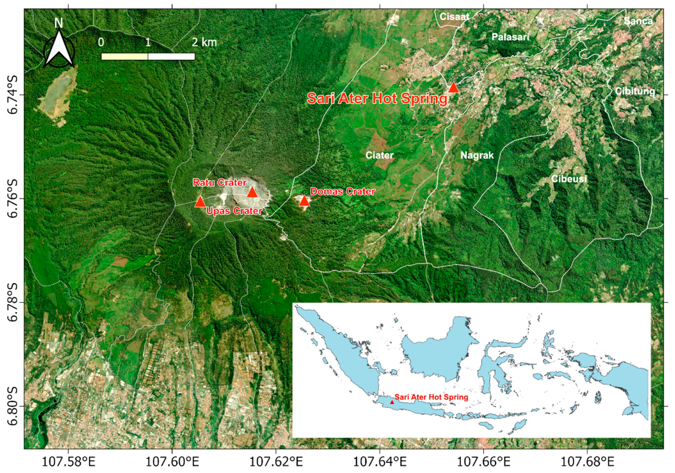
2.1. Lotemg–TPG Test and Application Site

The Lotemg–TPG unit test was performed in stages, including laboratory and field application tests. The design, manufacture, and laboratory-scale tests of the Lotemg–TPG were carried out in a private workshop with adequate facilities and equipment. Meanwhile, field-scale tests were carried out at the Sari Ater Hot Spring, Ciater, Subang, West Java, Indonesia (Figure 2). The hot springs in this area have been developed as a tourist attraction in the form of a bathing pool.

2.2. Research Stages

In general, the research stages were carried out in the sequence described in Figure 3, in the form of design, manufacture, and test, so that the Lotemg–TPG unit was realized, tested, and could be applied to low-temperature geothermal heat.

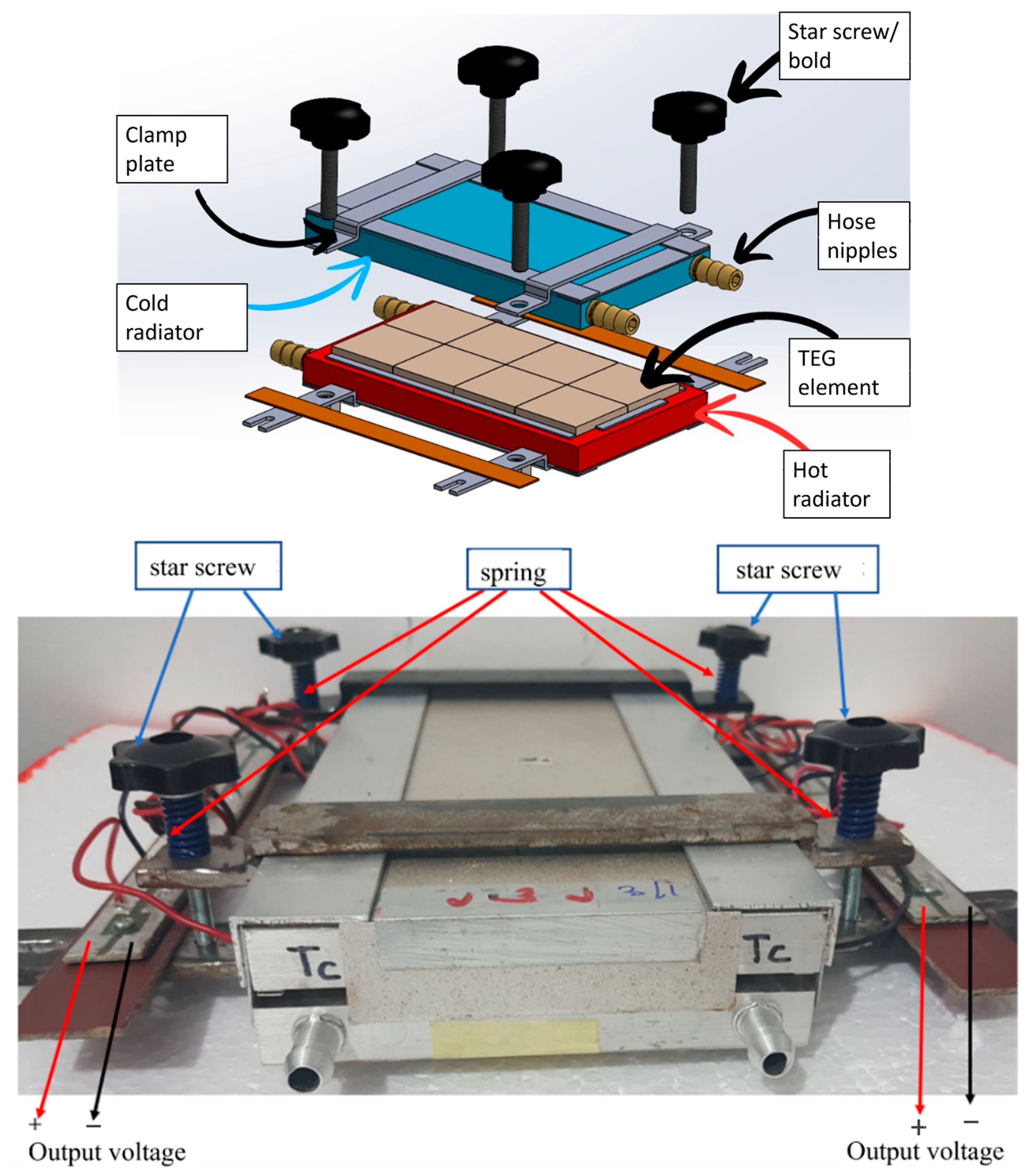
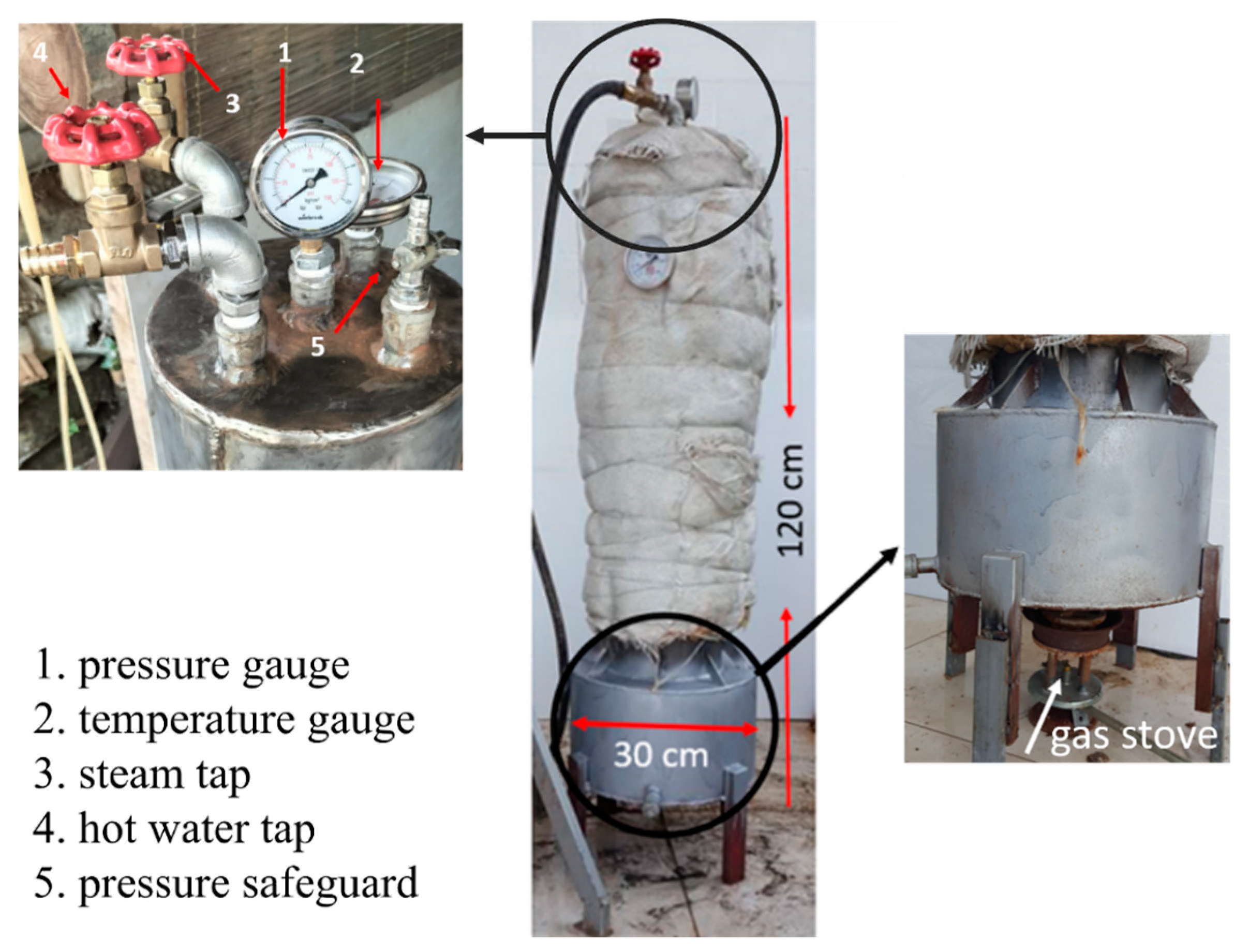
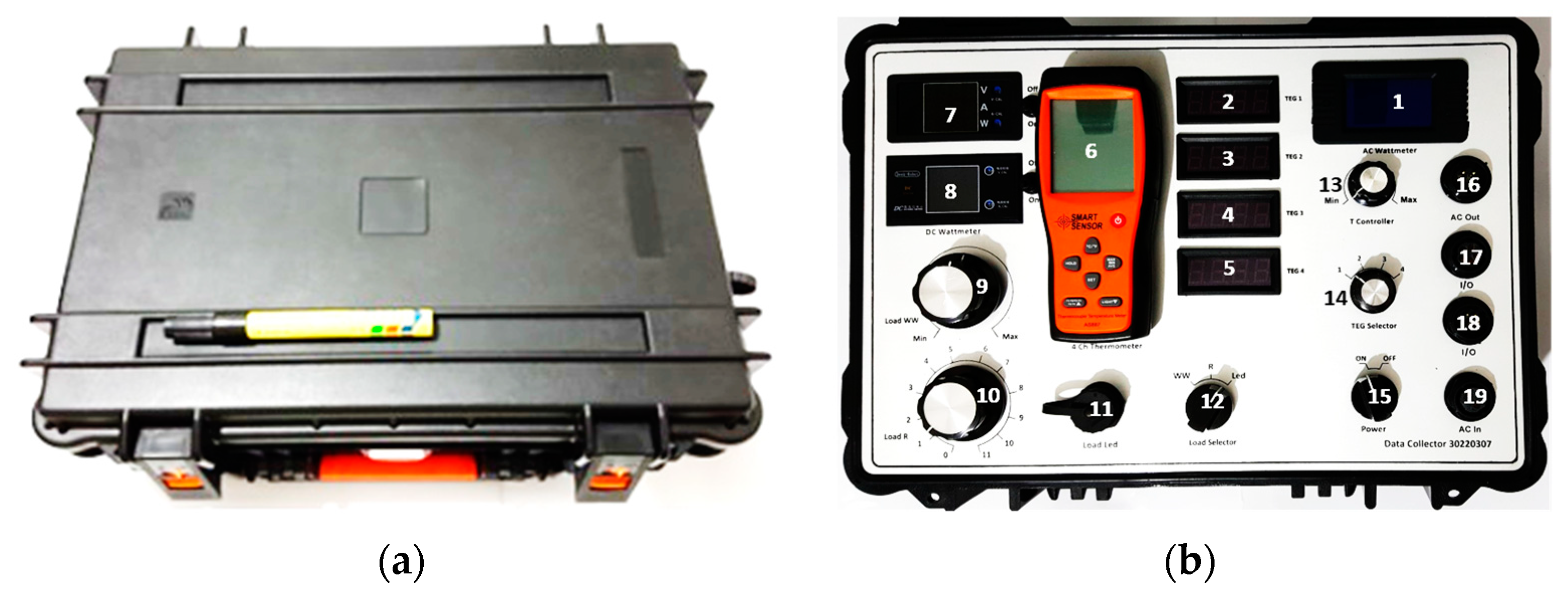
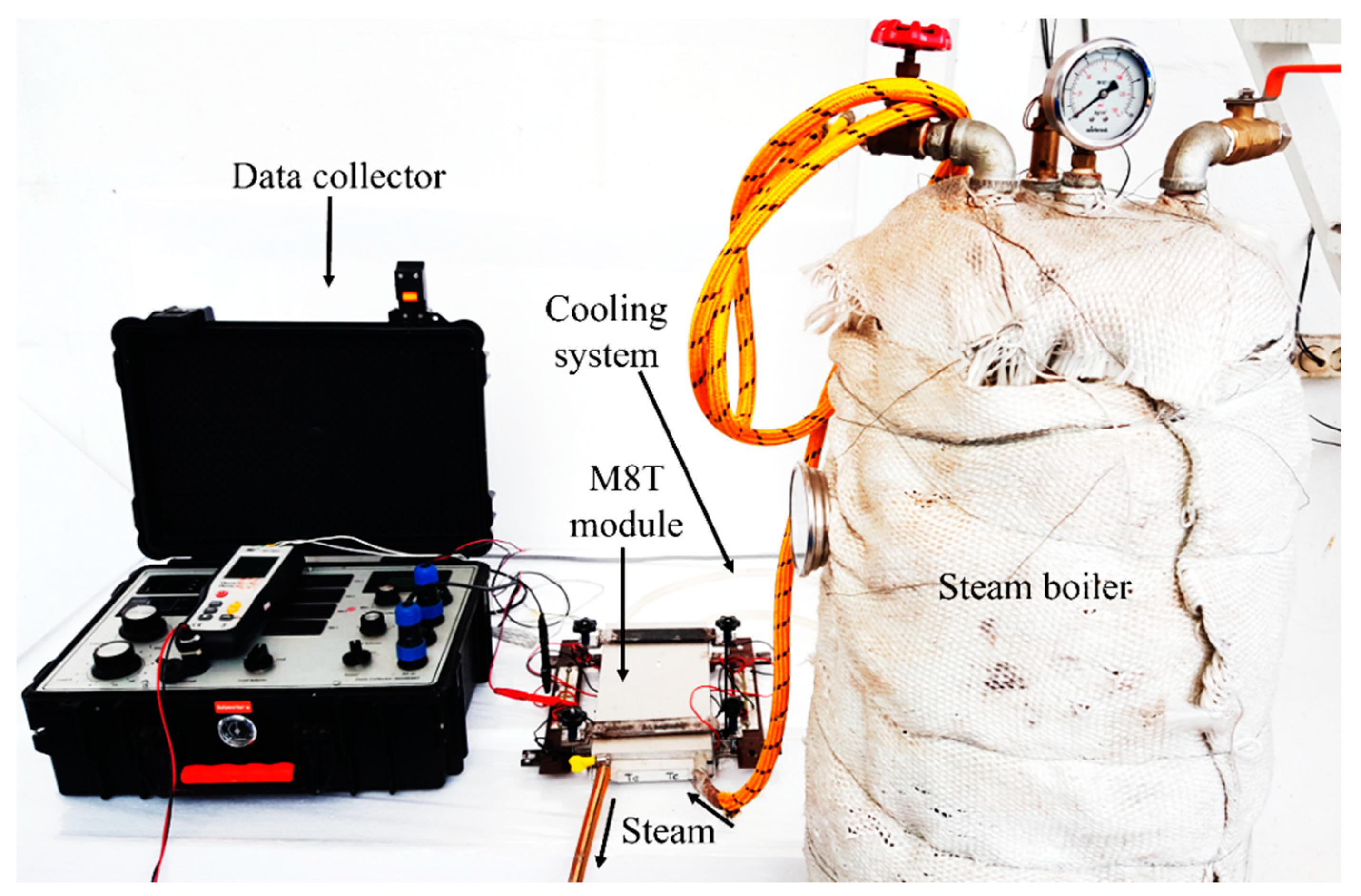
2.3. Device Manufacture and Performance Test of Lotemg–TPG

The primary basis of this research was manufacturing the Lotemg–TPG unit. The main component of the Lotemg–TPG unit is the TEG element type TEG1-241-1.4-1.2 (Figure 1b). This type of TEG element has previously been tested and had the best performance [40]. Some essential parameters of TEG type TEG1-241-1.4-1.2 are dimensions of 54.4 mm × 54.4 mm × 3.4 mm, efficiency of 4%, and operating temperature of 200 °C. To adjust the hot side and cold side of the TEG element to reach the specified temperature, a radiator is needed, which was attached to side of TEG element using thermal paste and reinforced with a holder. The hot-side and cold-side radiators were made of aluminum with dimensions of 25 cm × 12.5 cm × 1.4 cm (Figure 4, top). The radiator was made of aluminum and had many channels, so heat transfer occurred optimally. The arrangement of the hot-side radiator, with 8 TEG elements, and the cold-side radiator, glued together with thermal paste and a holder, is called the M8T module (Figure 4).
The power generation block frame was made of iron, which supported the main components of the Lotemg–TPG, which were packaged in the form of an M8T module and supporting components, i.e., hot-water and cold-water circulation systems. The hot-water and cold-water circulation systems were made similarly in the form of 1″ iron pipes connected to each radiator of the M8T module via a hose. The hoses connecting the hot pipes and hot-side radiators were made from heat-resistant materials. This block frame measured 40 cm long, 28 cm wide, and 50 cm high, weighing around 20 kg. Each block could be filled with 4 M8T modules (Figure 5).
Other supporting components in this research were for the purpose of laboratory tests and measurement equipment. For the purpose of laboratory tests, namely, tests on the M8T module and the Lotemg–TPG unit, a heat source provided by a steam boiler and a cold-water circulation system equipped with a pump were used. The steam boiler was designed and built with a height of 1 m and a diameter of 22 cm. The bottom of the steam boiler until was 20 cm high, and the diameter was made wider at 30 cm to maximize the heating process (Figure 6). This boiler can produce hot steam, hot water, or a combination of both at temperatures up to 170.0 °C (±2.5 °C) and pressures up to 5.0 kg/cm2 (±0.1 kg/cm2), with a heat-up time of approximately 45 min. The cooling system for the M8T module test and the Lotemg–TPG unit in the lab used an active system supported by a 12V DC submersible pump to circulate water between the cold-side radiator and the reservoir. During the application and field test of the Lotemg–TPG unit, hot-water circulation came from the bathtub faucet, and cold-water circulation came from the garden faucet at Sari Ater Hot Springs, Ciater.
A critical supporting component in this research was the integrated data collector, used as a test measurement tool. This integrated data collector was deliberately designed and made specifically to measure test parameters in this research. The function of each button, switch, display, and I/O socket is shown in Figure 7 and Table 1. During the measurements, external load resistance in the form of a cermet film resistor set was also used when testing the power characteristics of TEG type TEG1-241-1.4-1.2, the cermet film resistor set for the M8T module test, and the Lotemg–TPG unit test in the laboratory, as well as a 12 W 5 V LED lamp for the test at Sari Ater Hot Spring. Measurements were documented with the help of a recording camera.

3. Results and Discussion

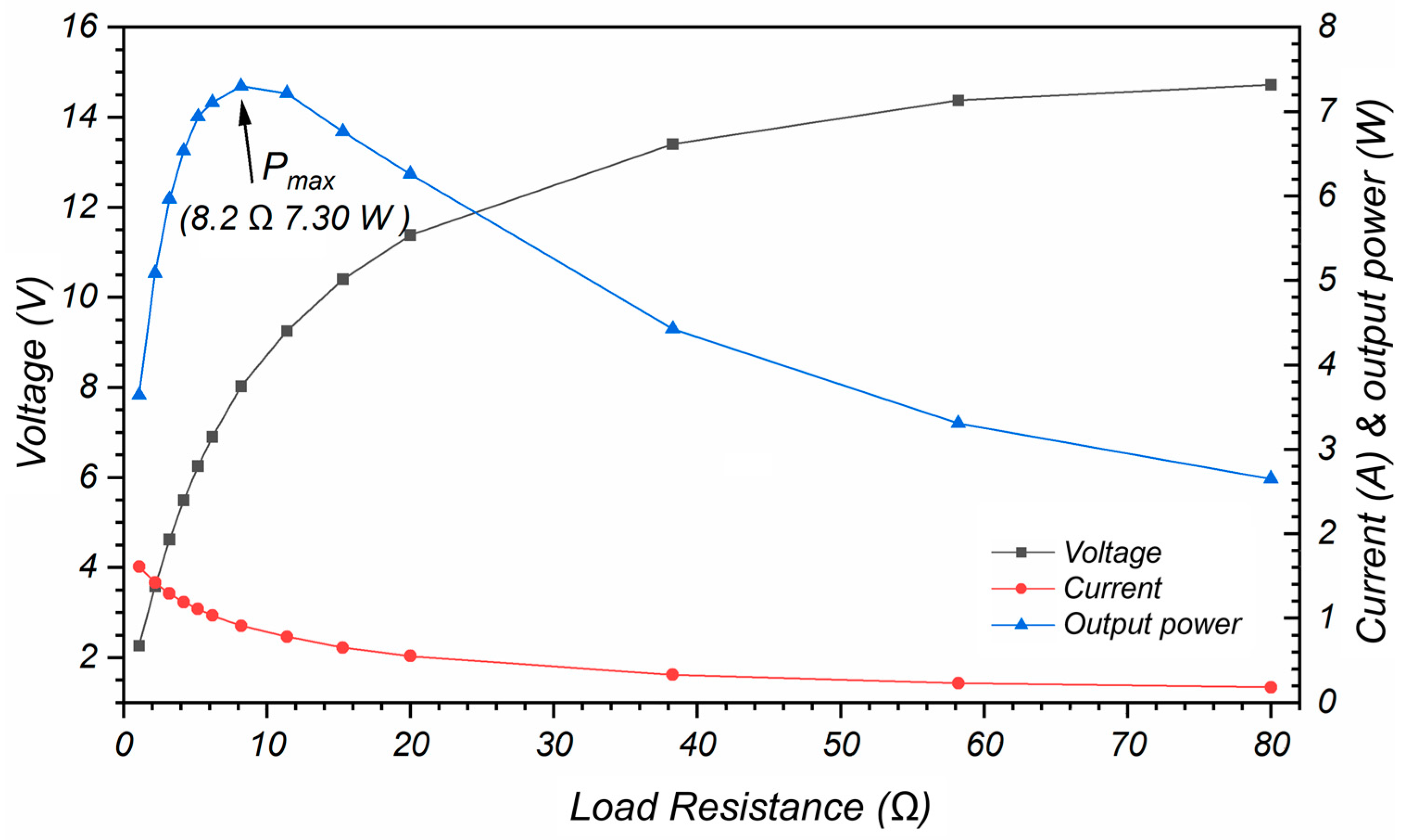
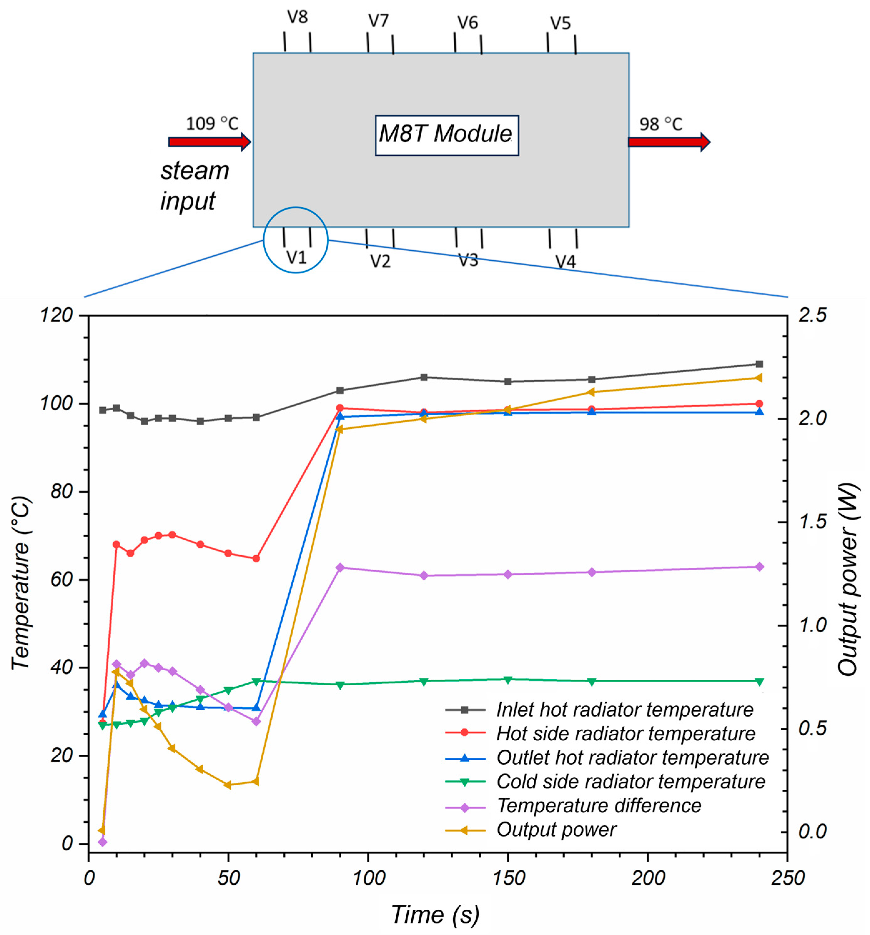
3.1. TEG Element Type TEG1-241-1.4-1.2 and M8T Module

The TEG elements were a crucial component in preparing the Lotemg–TPG unit. Different types of TEG elements were considered based on their operational temperature, efficiency, and output power. In a previous publication [40], tests were conducted on five types of TEG elements, including TEG1-241-1.4-1.2, TEG1-287, TEG1-199, SP1848, and TEC1-12706. The results showed that TEG1-241-1.4-1.2 produced the largest output power at various temperature differences, such as 4.9 W at ΔT = 100 °C. TEG1-241-1.4-1.2 can operate up to a temperature of 200 °C and has an efficiency of 4%. However, the output power, P, versus load resistance, R L , presented by Marpaung et al. [40] did not clearly show the maximum power, as it was limited to a maximum load resistance of <16 Ω. To obtain a larger load resistance range, repeated measurements using the same tool settings were conducted, and the results are presented in Figure 8. The load resistance range was obtained by setting the rotary switch for load resistance, R L , on the data collector (switch No. 12 in Figure 7b) and adding an external load in the form of a cermet film resistor set. The heat source was obtained from a 200 W/220 V electric heating element to maintain a stable hot-side temperature, T h , at 165 °C. The cooling system consisted of a radiator connected to a water tank, and circulation was assisted by a DC pump. The temperature of the cold side of the TEG element increased slightly and then stabilized at T c of 28 °C.
Based on the curve in Figure 8, by Ohm’s law, when the load was added slowly, the current decreased and the voltage increased. In the load range of 0–80 Ω, the maximum output power, P m a x , was observed to be 7.30 W, obtained when the load resistance was 8.2 Ω. This is in accordance with Equation (4), which states that maximum output power is obtained when the load resistance value approaches the internal resistance of TEG type TEG1-241-1.4-1.2, namely, 7.8 Ω. Increasing the maximum output power of the TEG element by means of impedance matching, namely, equalizing the load resistance to the internal resistance of the TEG element, was also carried out and explained in research by Ahiska and Mamur [23], Twaha et al. [20], Zhang et al. [41], Morais et al. [42], and Jaziri et al. [14]. Morais et al. [42] further explained that the arrangement of TEG elements in the design of a thermoelectric-based power plant influences the total internal resistance of the TEG. The arrangement of TEG elements in a series will produce a large output voltage and internal resistance. On the other hand, the arrangement of TEG elements in parallel will produce a large current and small internal resistance.
After obtaining the TEG1-241-1.4-1.2 type as the TEG element with the best performance, the next step was to make the M8T module. The construction of this module consists of eight TEG elements arranged between the hot-side radiator and the cold-side radiator (Figure 4). In detail, the eight TEG elements were arranged in two back-to-back paths, making it easier to arrange the wiring. The hot-side and cold-side radiators were also arranged with the input–output channels back-to-back to facilitate the piping line and avoid temperature influences between the two. The documentation for testing this module using a heat source from a steam boiler is presented in Figure 9. This module utilized an active cooling system, where the circulation of cold water between the water tank and the cold-side radiator was assisted by a pump. The schematic arrangement of the eight TEG elements in the M8T module is shown in Figure 10, top. Assuming the hot-side radiator and cold-side radiator were able to distribute heat uniformly on both sides of the TEG element, measurements of temperature and power characteristics over time were only carried out on TEG element 1 (V1), and the curves are presented in Figure 10, bottom.
During the testing of the M8T module, the steam boiler temperature was set to 135.0 °C (±2.5 °C) with a pressure of 4.0 kg/cm2 (±0.1 kg/cm2) and was directed to the hot-side radiator inlet via a heat-resistant hose. At these temperature and pressure levels, the temperature at the inlet hot radiator, T3, remained relatively constant, reaching an average temperature of 105.70 °C after 90 s. The heat from the hot steam heated up the hot side of the radiator, which then passed on to the TEG elements to produce an electric potential. Based on the curve in Figure 10, during the first 60 s, the temperature on the hot side of the radiator remained unstable and even decreased slightly due to the cold water trapped inside, left over from the previous experiment. After reaching a stable condition, the average temperature of the hot-side radiator was T h = 98.86 °C, with the outlet hot radiator temperature still relatively high at T4 = 97.72 °C. The temperature of the cold-side radiator experienced a slight increase as a result of the heat transfer from the hot steam through the TEG element, and then remained relatively constant at an average temperature of 36.92 °C. This indicates that the cooling system was working well. Under stable conditions, an average temperature difference, ∆T, of around 61.94 °C was obtained, which produced an output power of around 2.06 W at TEG element 1 (V1), with a load resistance of 7.8 Ω. In this M8T module test, the current, voltage, and output power measurements were taken only on TEG element 1. Assuming that the eight TEG elements were in the same condition (with the same temperature difference), the measurements on TEG element 1 can represent the other TEG elements. This output power was slightly lower than the output power resulting from the TEG type TEG1-241-1.4-1.2 characteristic test conducted by Marpaung et al. [40] on the same ∆T. Assuming that all TEG elements in the M8T module were in the same condition, they would produce a total output power of 16.48 W. The eight TEG elements in the M8T module can be connected in series, parallel, or any combination to meet output voltage requirements for future tests and applications.

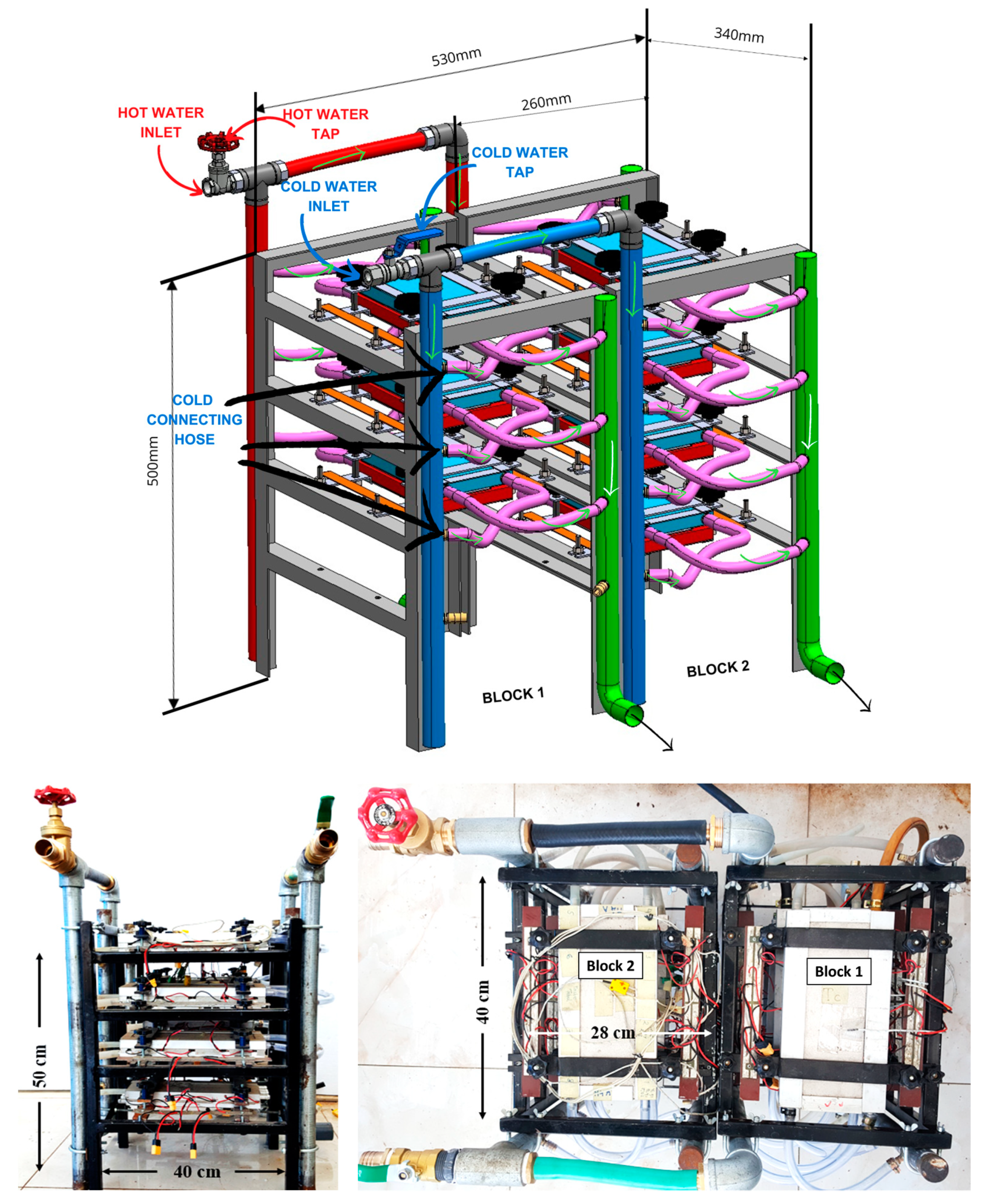
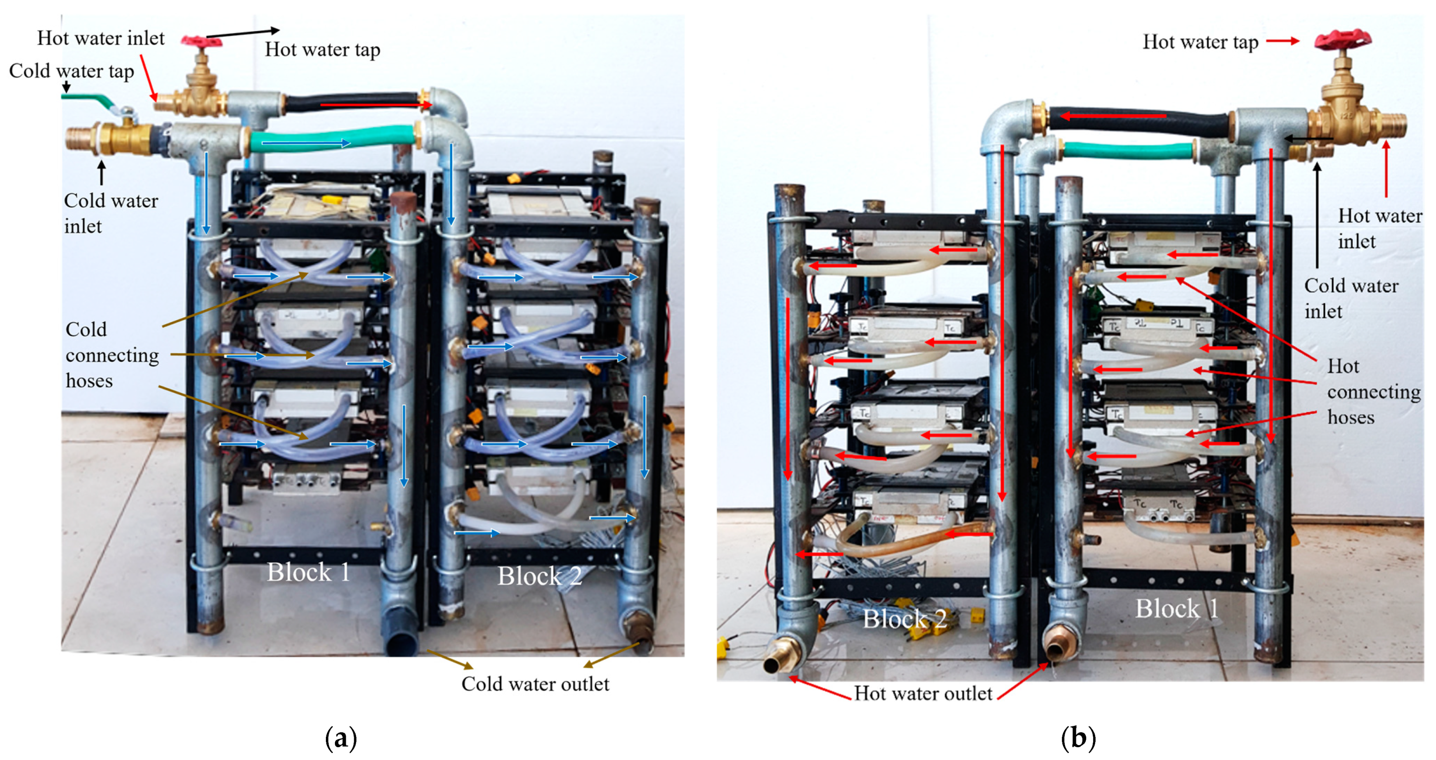
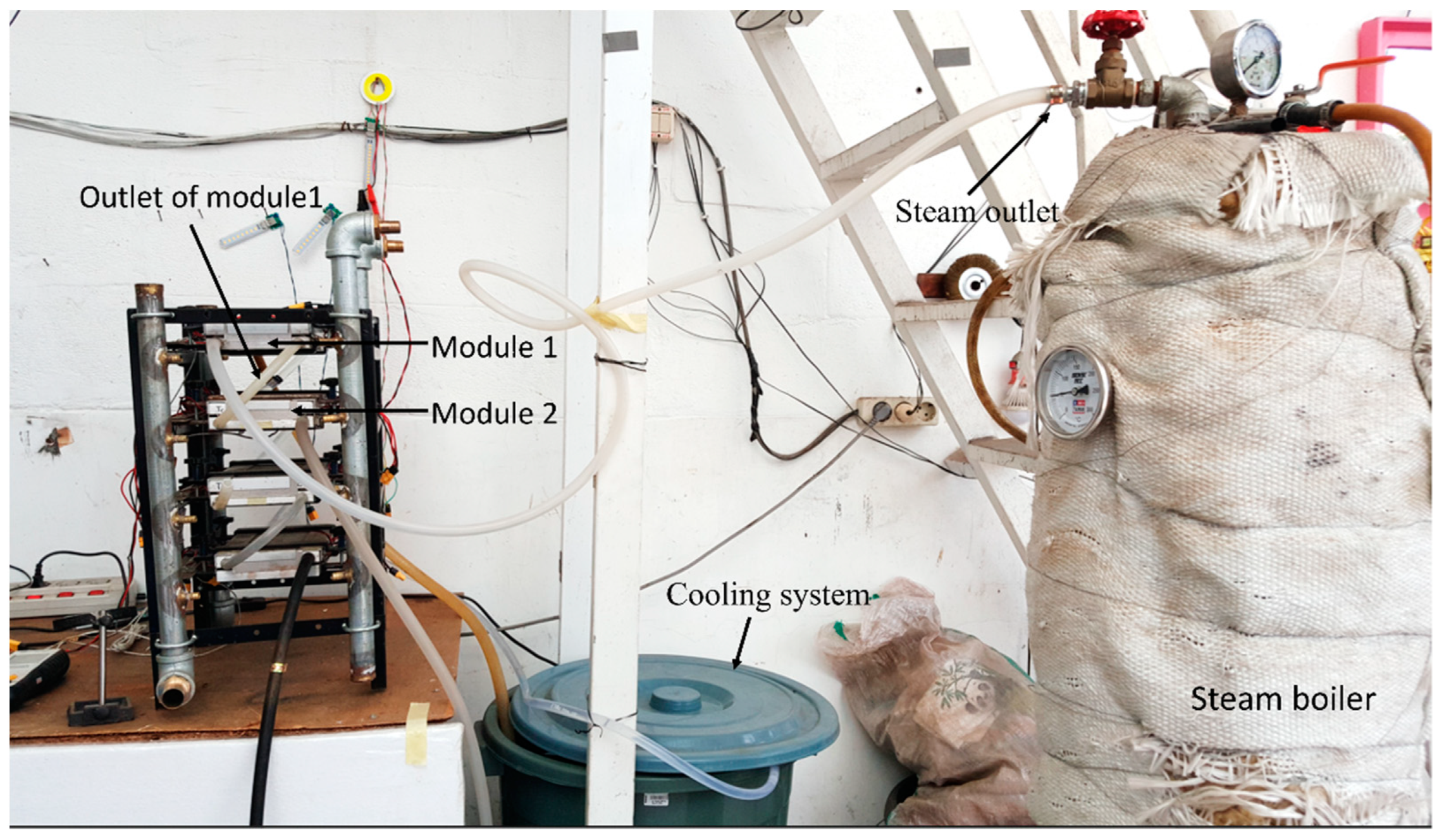
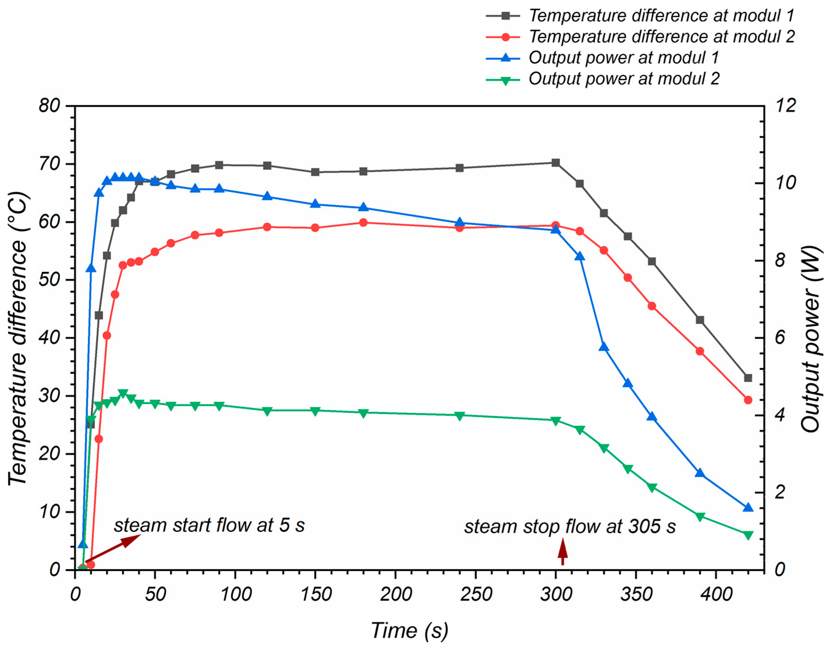
3.2. Lotemg–TPG Unit Block Frame and Laboratory Test

The Lotemg–TPG unit is an integrated power generation system consisting of seven M8T modules in two blocks with a solid frame equipped with hot-side and cold-side circulation systems and TEG element output wiring lines. The first block consists of three M8T modules, and the second block consists of four M8T modules. The radiators on each M8T module in the blocks were interconnected with the central piping system, hot-water hoses, and cold-water hoses. The front and top views, accompanied by the finished product size of the Lotemg–TPG unit, are shown in Figure 11, bottom. The connection between the radiator and the central pipe through the hose is shown in Figure 12. The blue arrow illustrates the direction of cooling water flow, distributed through a hose from a 1″ pipe to each Block 1 and Block 2 module. The hot fluid flows through the tap, illustrated by the red arrow line, and is distributed from the 1″ pipe to each module through a heat-resistant hose up to 260 °C.
The design of the wiring between TEG elements and M8T modules in Lotemg–TPG is flexible. The eight TEG elements in each M8T module can be connected in series or parallel to adjust the voltage and current output, as desired. When a large potential difference is needed, the TEG elements are connected in series. Conversely, when a large current is needed, the TEG elements are connected in parallel. To obtain certain voltage and current values, combinations of TEG elements in series and parallel can also be used. The same applies to the arrangement between M8T modules in Lotemg–TPG. Some M8T modules can be connected in series or parallel to achieve the desired output. According to the explanation of Morais et al. [42], the combination of circuits between TEG elements and between M8T modules is also useful for obtaining maximum output power. The electrical energy produced by Lotemg–TPG is in the form of direct current (DC) electricity.
The steam boiler previously used to test the M8T module was repurposed to test the performance of the Lotemg–TPG unit. However, there was limited hot-water steam flow capacity to supply all seven M8T modules on the Lotemg–TPG. Therefore, during the Lotemg–TPG unit test, using a heat source from the steam boiler, only Module 1 and Module 2 in one of the blocks were operated, as shown in Figure 13. Hot steam from the steam boiler was directed to the hot-side radiator of Module 1. The hot-side radiator output from Module 1 then flowed back to the Module 2 radiator. The cold-side radiators in Module 1 and Module 2 were connected to the cooling system with the help of a pump.
Out of eight TEG elements in Module 1 and Module 2, only four TEG elements at one line side (see Figure 4, top and Figure 10, top) were measured. In order to achieve maximum power, an impedance matching technique was used, which has been explained by Morais et al. [42]. A series-parallel combination of four TEG elements was used, as shown in Figure 14. The results of the calculations showed that the internal resistance of the measured elements was the same as the internal resistance of the TEG1-241-1.4-1.2 element type, which was 7.8 Ω. To achieve maximum power, the load resistance, R L , should be set close to 7.8 Ω. In this test, the load resistance value was approximated by a parallel array of 4 pieces of 33 Ω resistors to obtain 8.25 Ω. This load value was also relatively close to the load resistance, which produced maximum output power, P m a x , in Figure 8, which was 8.2 Ω.
The results of the Lotemg–TPG test measurements with a heat source as a steam boiler on four TEG elements in Module 1 and Module 2 are presented in the form of curves of temperature difference (left axis) and output power (right axis) versus operating time, shown in Figure 15. With a heat source in the form of hot steam from a steam boiler and the previous radiator conditions emptied, the temperature in the radiator quickly rose and reaches a stable condition in <60 s. The output power of Module 1 (blue line) was much greater than that of Module 2 (green line) because the heat was received first by Module 1, while Module 2 only received the residual heat. The average output power in Module 1 in a stable state was around 9.48 W at an average temperature difference, ΔT, of around 69.21 °C for the four TEG elements, so that for each TEG, the output power was 2.37 W. This output power was also smaller than the output power of the characteristic test of TEG type TEG1-241-1.4-1.2 by Marpaung et al. [40] at the same ΔT, which was probably due to the load resistance (8.25 Ω) being more significant than the internal resistance of the four-element TEG circuit (7.8 Ω). Meanwhile, the four TEG elements at Module 2, in a stable state with an average temperature difference, ΔT, of 58.56 °C, still produced an average power of 4.12 W. These values were relatively constant in the time range of 60 to 300 s (stable state), which indicates that the modules in the Lotemg–TPG unit worked well. When the flow of hot steam from the steam boiler was turned off at 305 s, the temperature difference, ΔT, and output power, P, decreased slowly due to the residual heat remaining in the hot-side radiator. The test results on Module 1 were assumed to be representative of the other modules in Lotemg–TPG, considering that all M8T modules were made uniformly and placed in the generating frame with similar conditions, especially for the hot-side temperature, T h , and cold-side temperature, T c .

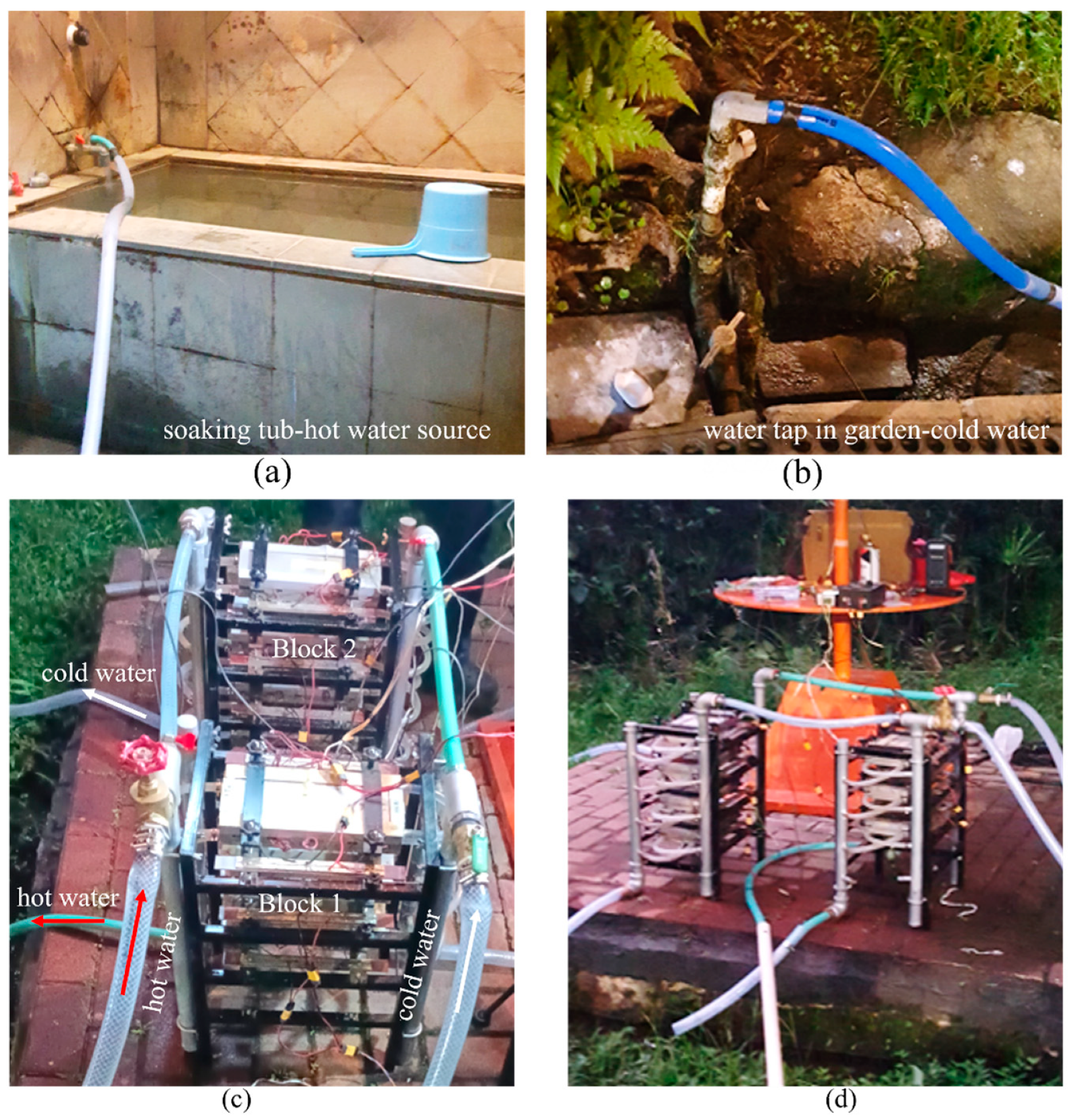
3.3. Application and Field Test of Lotemg–TPG Unit at Sari Ater Hot Springs

Sari Ater Hot Spring is a natural tourist attraction managed by PT Sari Ater and located in Ciater Village, Ciater District, Subang Regency, Wes Java Province, Indonesia. It is situated on the northeast slope of Mt. Tangkuban Parahu and is part of the geothermal manifestation system. The temperature of the hot spring ranges from 43 to 46 °C, according to direct measurements. These results are consistent with research by Nasution et al. [5] and Sentosa et al. [6], considering the dynamics of the Mt. Tangkuban Parahu geothermal system. The relatively low temperature of this hot spring was utilized for electricity production through TEG-based energy conversion equipment previously created and tested.
The Lotemg–TPG unit tested at the Sari Ater hot springs consisted of two blocks (Figure 16). The hot-water source was taken from the soak room tap and channeled to the power generation system via a 6 m hose. Measurements indicated that the hot-water discharge from the soaking room tap was 7.74 L per minute at 45.50 °C. At the main inlet tap of the power generation system, the hot-water temperature dropped to 43 °C. However, the hot-water channel in the form of an ordinary hose with a length of up to 6 m was less than ideal due to heat radiation occurring along the hose. After supplying heat to the hot-side radiator for seven M8T modules, the hot water from the power generation system was still 41 °C. This means the power generation system can only absorb 2 °C of heat from hot water at 43 °C and a flow rate of 7.74 L per minute. The cold-water circulation utilized tap water available in the park, which was channeled to the power generation system via a 10 m hose.
The Lotemg–TPG unit was tested with a heat source from a Sari Ater Hot Spring. The tests involved measuring the temperature of the hot-side radiator ( T h ) and cold side ( T c ), current (I), and output voltage (V) of the M8T module. The measurements were conducted using the data collector on Module 1 in Block 1 and Module 4 in Block 2. Due to the relatively low temperature of the hot spring, it will generate a low voltage. Therefore, the eight TEG elements in Module 1 and Module 4 were wired in a series connection to deliver a voltage capable of supplying LED lights. The results are presented in curves of output power, P, and temperature difference, ΔT, versus time, t in Figure 17. P1 is the output power on Module 1 in Block 1 and P2 is the power on Module 4 in Block 2. According to the temperature difference, ΔT, versus time, t, it took around 60 s for the Lotemg–TPG unit to reach a stable condition, with T h 1 around 40.63 °C and T h 2 around 40.40 °C. With a passive cooling system, where cold water flows directly from the tap in the garden without the help of a pump, the temperature of the cold-side radiators T c 1 and T c 2 only experienced a slight increase and then stabilized, with T c 1 around 23.25 °C and T c 2 around 23.42 °C. The difference in T h 1 and T h 2 as well as T c 1 and T c 2 caused a difference in ΔT1 (17.38 °C) and ΔT2 (16.98 °C), which affected the output power. The output power from Module 1 in Block 1 was slightly greater than that of Module 4 in Block 2. This was due to the limited flow of hot water from the tap, so the hot-water supply to Block 2 was not as optimal as that in in Block 1, where the hot water passed first. After reaching a stable condition, the average electrical power produced by Module 1 was 1.30 W and that by Module 4 was 1.29 W. The Lotemg–TPG unit was capable of producing a total power of around 9.10 W with seven M8T modules installed. Taking the average output power in Modules 1 and 4, each TEG element produced 0.16 W of output power. From the results of the recent study of TEG applications in low-temperature geothermal energy conducted by Liao et al. [43], each TEG element was able to produce 0.96 W at a temperature difference of 73 °C. Some factors that were presumed to cause the results of this study to be lower than those of Liao et al. were the low temperature of the hot springs, the low flow rate of the hot water, and the use of a far simpler and cheaper heat exchanger. The power output of the Lotem–TPG with a heat source in the form of the Sari Ater Hot Spring, Ciater, was still in the form of direct current (DC), where each module produced an average output voltage of 3.50 V and could be used directly to supply 5 V 12 W LED light sticks with a relatively bright flame. Although the power output was relatively small when compared to the results of the Lotemg–TPG unit test using a steam boiler heat source, the unit is still worth developing. This is because the heat source from hot springs is available for free, and the unit can operate stably. Several improvements to the hot-water circulation system by adding insulators can increase the output power of the Lotemg–TPG unit. The addition of an external power regulator is also needed so that the Lotemg–TPG unit can produce maximum power and safely supply electronic equipment.

4. Conclusions

The Lotemg–TPG unit was successfully manufactured and tested in this research. The Lotemg–TPG unit is a solid-state TEG-based energy conversion device that directly converts low-temperature heat sources into electrical energy. This unit comprised seven M8T modules in two frame blocks equipped with hot-water and cold-water circulation channels. The M8T module is the main part of the Lotemg–TPG, which consists of eight TEG elements of type TEG1-241-1.4-1.2, flanked by a hot-side radiator and a cold-side radiator. A more detailed load test on TEG type TEG1-241-1.4-1.2 obtained a maximum power of 7.30 W at a load of 8.2 Ω. The test results of the M8T module with a steam boiler heat source showed that each TEG element could produce 2.06 W of power at ∆T 61.94 °C. After being assembled in the Lotemg–TPG unit with a steam boiler heat source, the test results showed that the series-parallel combination of four TEG elements could produce 2.37 W of power at ∆T 69.21 °C. Installing the Lotemg–TPG unit in the Sari Ater Hot Spring was relatively easy, namely, by connecting the hot-water inlet to the tap at the heat source in the soaking room and the cold-water inlet to the water tap in the garden. The measurement results showed that at ∆T 17.38 °C, Module 1 with all TEG elements in series connection could produce 1.30 W of power, so the total power of the Lotemg–TPG unit was around 9.10 W. This result is quite good considering that the heat source was obtained for free and the device can operate to produce stable power.

Author Contributions

Conceptualization, A.S. and W.S.; methodology, N.K.L. and W.S.; software, S. and W.S.; validation, N.K.L., A.S. and W.S.; formal analysis, H.M., S. and W.S.; investigation, N.K.L., A.S. and W.S.; resources, H.M.; data curation, H.M. and S.; writing—original draft preparation, H.M. and S.; writing—review and editing, S., N.K.L., A.S. and W.S.; visualization, H.M. and S.; supervision, N.K.L., A.S. and W.S.; project administration, H.M. and W.S.; funding acquisition, H.M. All authors have read and agreed to the published version of the manuscript.

Funding

This research received no external funding.

Data Availability Statement

Data are contained within the article.

Acknowledgments

The authors would like to thank PT Sari Ater, which manages the Sari Ater Hot Springs Tourist Attraction, for allowing this research to take place.

Conflicts of Interest

The authors declare no conflicts of interest.

References

  1. Rizaty, M.A. Kapasitas PLTP Indonesia Terbesar Kedua Di Dunia Pada 2022. Available online: https://dataindonesia.id/energi-sda/detail/kapasitas-pltp-indonesia-terbesar-kedua-di-dunia-pada-2022 (accessed on 13 March 2023).
  2. Bina, S.M.; Jalilinasrabady, S.; Fujii, H.; Pambudi, N.A. Classification of Geothermal Resources in Indonesia by Applying Exergy Concept. Renew. Sustain. Energy Rev. 2018, 93, 499–506. [Google Scholar] [CrossRef]
  3. Hochstein, M.P. Classification and Assessment of Geothermal Resources; Dickson, M.H., Fanelli, M., Eds.; UNITAR/UNDP: Rome, Italy, 1990; pp. 31–57. [Google Scholar]
  4. Ronald DiPippo Geothermal Power Plants: Principles, Applications, Case Studies and Environmental Impact; Elsevier: Amsterdam, The Netherlands, 2015; ISBN 9780081008799.
  5. Nasution, A.; Kartadinata, M.N.; Kobayashi, T.; Siregar, D.; Sutaningsih, E.; Hadisantono, R.; Kadarstia, E. Geology, Age Dating and Geochemistry of the Tangkuban Parahu Geothermal Area, West Java, Indonesia. J. Geotherm. Res. Soc. Jpn. 2004, 26, 285–303. [Google Scholar] [CrossRef]
  6. Sentosa, R.A.; Haryanto, N.S.A.D.; Gentana, D. Land Surface Temperature Pada Manifestasi Permukaan Panasbumi: Studi Kasus Gunung Tangkuban Parahu, Jawa Barat. Padjadjaran Geosci. J. 2018, 2, 376–386. [Google Scholar]
  7. Rana, S.; Orr, B.; Iqbal, A.; Ding, L.C.; Akbarzadeh, A.; Date, A. Modelling and Optimization of Low-Temperature Waste Heat Thermoelectric Generator System. Energy Procedia 2017, 110, 196–201. [Google Scholar] [CrossRef]
  8. Remeli, M.F.; Tan, L.; Date, A.; Singh, B.; Akbarzadeh, A. Simultaneous Power Generation and Heat Recovery Using a Heat Pipe Assisted Thermoelectric Generator System. Energy Convers. Manag. 2015, 91, 110–119. [Google Scholar] [CrossRef]
  9. Hettiarachchi, H.D.M.; Golubovic, M.; Worek, W.M.; Ikegami, Y. Optimum Design Criteria for an Organic Rankine Cycle Using Low-Temperature Geothermal Heat Sources. Energy 2007, 32, 1698–1706. [Google Scholar] [CrossRef]
  10. Yu, K.; Zhou, Y.; Liu, Y.; Liu, F.; Hu, L.; Ao, W.; Zhang, C.; Li, Y.; Li, J.; Xie, H. Near-Room-Temperature Thermoelectric Materials and Their Application Prospects in Geothermal Power Generation. Geomech. Geophys. Geo-Energy Geo-Resour. 2020, 6, 12. [Google Scholar] [CrossRef]
  11. Velmre, E. Thomas Johann Seebeck (1770–1831). Est. J. Eng. 2007, 13, 276. [Google Scholar] [CrossRef]
  12. Rowe, D.M. Review, Thermoelectric Waste Heat Recovery as a Renewable Energy Source. Int. J. Innov. Energy Syst. Power 2006, 1, 13–23. [Google Scholar]
  13. Snyder, G.J. Small Thermoelectric Generators. Electrochem. Soc. Interface 2008, 17, 54–56. [Google Scholar] [CrossRef]
  14. Jaziri, N.; Boughamoura, A.; Müller, J.; Mezghani, B.; Tounsi, F.; Ismail, M. A Comprehensive Review of Thermoelectric Generators: Technologies and Common Applications. Energy Rep. 2020, 6, 264–287. [Google Scholar] [CrossRef]
  15. Abdel-Motaleb, I.M.; Qadri, S.M. Thermoelectric Devices: Principles and Future Trends. arXiv 2017, arXiv:1704.07742. [Google Scholar]
  16. Zulkepli, N.; Yunas, J.; Mohamed, M.A.; Hamzah, A.A. Review of Thermoelectric Generators at Low Operating Temperatures: Working Principles and Materials. Micromachines 2021, 12, 734. [Google Scholar] [CrossRef] [PubMed]
  17. Zoui, M.A.; Bentouba, S.; Stocholm, J.G.; Bourouis, M. A Review on Thermoelectric Generators: Progress and Applications. Energies 2020, 13, 3606. [Google Scholar] [CrossRef]
  18. Ravindra, N.M.; Jariwala, B.; Bañobre, A.; Maske, A. Thermoelectrics; SpringerBriefs in Materials; Springer International Publishing: Cham, Switzerland, 2019; ISBN 978-3-319-96339-6. [Google Scholar]
  19. Northwestern_University Thermoelectric Properties of Materials. Available online: https://thermoelectrics.matsci.northwestern.edu/thermoelectrics/index.html (accessed on 22 November 2021).
  20. Twaha, S.; Zhu, J.; Yan, Y.; Li, B. A Comprehensive Review of Thermoelectric Technology: Materials, Applications, Modelling and Performance Improvement. Renew. Sustain. Energy Rev. 2016, 65, 698–726. [Google Scholar] [CrossRef]
  21. Lee, H. Thermoelectrics: Design and Materials, 1st ed.; John Wiley & Sons, Inc.: Hokoben, NJ, USA; Western Michigan University: Kalamazoo, MI, USA, 2017; ISBN 9781118848951. [Google Scholar]
  22. Rowe, D.M. Thermoelectrics Handbook Macro to Nano; CRC Press: Boca Raton, FL, USA, 2006; ISBN 9781315220390. [Google Scholar]
  23. Ahiska, R.; Mamur, H. Design and Implementation of a New Portable Thermoelectric Generator for Low Geothermal Temperatures. IET Renew. Power Gener. 2013, 7, 700–706. [Google Scholar] [CrossRef]
  24. Liu, C.; Chen, P.; Li, K. A 500 W Low-Temperature Thermoelectric Generator: Design and Experimental Study. Int. J. Hydrogen Energy 2014, 39, 15497–15505. [Google Scholar] [CrossRef]
  25. Ziapour, B.M.; Saadat, M.; Palideh, V.; Afzal, S. Power Generation Enhancement in a Salinity-Gradient Solar Pond Power Plant Using Thermoelectric Generator. Energy Convers. Manag. 2017, 136, 283–293. [Google Scholar] [CrossRef]
  26. Kumar, S.; Roy, D.; Ghosh, S. Thermodynamic Assessment of TEG-ORC Combined Cycle Powered by Solar Energy. Int. J. Renew. Energy Technol. 2017, 8, 346. [Google Scholar] [CrossRef]
  27. Zare, V.; Palideh, V. Employing Thermoelectric Generator for Power Generation Enhancement in a Kalina Cycle Driven by Low-Grade Geothermal Energy. Appl. Therm. Eng. 2018, 130, 418–428. [Google Scholar] [CrossRef]
  28. Gholamian, E.; Habibollahzade, A.; Zare, V. Development and Multi-Objective Optimization of Geothermal-Based Organic Rankine Cycle Integrated with Thermoelectric Generator and Proton Exchange Membrane Electrolyzer for Power and Hydrogen Production. Energy Convers. Manag. 2018, 174, 112–125. [Google Scholar] [CrossRef]
  29. Khanmohammadi, S.; Saadat-Targhi, M.; Al-Rashed, A.A.A.A.; Afrand, M. Thermodynamic and Economic Analyses and Multi-Objective Optimization of Harvesting Waste Heat from a Biomass Gasifier Integrated System by Thermoelectric Generator. Energy Convers. Manag. 2019, 195, 1022–1034. [Google Scholar] [CrossRef]
  30. Maneewan, S.; Chindaruksa, S. Thermoelectric Power Generation System Using Waste Heat from Biomass Drying. J. Electron. Mater. 2009, 38, 974–980. [Google Scholar] [CrossRef]
  31. Hsu, C.-T.; Huang, G.-Y.; Chu, H.-S.; Yu, B.; Yao, D.-J. Experiments and Simulations on Low-Temperature Waste Heat Harvesting System by Thermoelectric Power Generators. Appl. Energy 2011, 88, 1291–1297. [Google Scholar] [CrossRef]
  32. Niu, X.; Yu, J.; Wang, S. Experimental Study on Low-Temperature Waste Heat Thermoelectric Generator. J. Power Sources 2009, 188, 621–626. [Google Scholar] [CrossRef]
  33. Suter, C.; Jovanovic, Z.R.; Steinfeld, A. A 1kWe Thermoelectric Stack for Geothermal Power Generation—Modeling and Geometrical Optimization. Appl. Energy 2012, 99, 379–385. [Google Scholar] [CrossRef]
  34. Li, K.; Garrison, G.; Moore, M.; Zhu, Y.; Liu, C.; Horne, R.; Petty, S. An Expandable Thermoelectric Power Generator and the Experimental Studies on Power Output. Int. J. Heat Mass Transf. 2020, 160, 120205. [Google Scholar] [CrossRef]
  35. Lee, K.-T.; Lee, D.-S.; Chen, W.-H.; Lin, Y.-L.; Luo, D.; Park, Y.-K.; Bandala, A. An Overview of Commercialization and Marketization of Thermoelectric Generators for Low-Temperature Waste Heat Recovery. iScience 2023, 26, 107874. [Google Scholar] [CrossRef]
  36. Xie, H.; Gao, T.; Long, X.; Sun, L.; Wang, J.; Xia, E.; Li, S.; Li, B.; Li, C.; Gao, M.; et al. Design and Performance of a Modular 1 Kilowatt-Level Thermoelectric Generator for Geothermal Application at Medium-Low Temperature. Energy Convers. Manag. 2023, 298, 117782. [Google Scholar] [CrossRef]
  37. Ahiska, R.; Mamur, H. Development and Application of a New Power Analysis System for Testing of Geothermal Thermoelectric Generators. Int. J. Green Energy 2016, 13, 672–681. [Google Scholar] [CrossRef]
  38. Li, K.; Garrison, G.; Zhu, Y.; Moore, M.; Liu, C.; Hepper, J.; Bandt, L.; Horne, R.; Petty, S. Thermoelectric Power Generator: Field Test at Bottle Rock Geothermal Power Plant. J. Power Sources 2021, 485, 229266. [Google Scholar] [CrossRef]
  39. Catalan, L.; Aranguren, P.; Araiz, M.; Perez, G.; Astrain, D. New Opportunities for Electricity Generation in Shallow Hot Dry Rock Fields: A Study of Thermoelectric Generators with Different Heat Exchangers. Energy Convers. Manag. 2019, 200, 112061. [Google Scholar] [CrossRef]
  40. Marpaung, H.; Singarimbun, A.; Srigutomo, W.; Lasmi, N.K. Thermoelectric Application of TEG1-241-1.4-1.2 for Power Generation from Low Temperature Geothermal Fluid. Adv. Sci. Technol. 2023, 126, 67–77. [Google Scholar] [CrossRef]
  41. Zhang, Z.; Wu, Y.; Li, W.; Xu, D. Performance of a Solar Thermoelectric Power-Harvesting Device Based on an All-Glass Solar Heat Transfer Pipe and Gravity-Assisted Heat Pipe with Recycling Air Cooling and Water Cooling Circuits. Energies 2020, 13, 947. [Google Scholar] [CrossRef]
  42. Morais, F.; Carvalhaes-Dias, P.; Duarte, L.; Spengler, A.; De Paiva, K.; Martins, T.; Cabot, A.; Dias, J.S. Optimization of the TEGs Configuration (Series/Parallel) in Energy Harvesting Systems with Low-Voltage Thermoelectric Generators Connected to Ultra-Low Voltage DC-DC Converters. Energies 2020, 13, 2297. [Google Scholar] [CrossRef]
  43. Liao, J.; Xie, H.; Wang, J.; Sun, L.; Long, X.; Li, C.; Gao, T.; Xia, E. Effect of Operating Conditions on the Output Performance of a Compact TEG for Low-Grade Geothermal Energy Utilization. Appl. Therm. Eng. 2024, 236, 121878. [Google Scholar] [CrossRef]
Figure 1. (a) A diagram showing the structure of a TEG created using semiconductors, modified from Jaziri et al. [14], and (b) an example of a commercial TEG.
Designs 08 00060 g001
Figure 2. Field test location for the Lotemg–TPG unit, namely, the Sari Ater Hot Spring, Ciater, Subang, West Java, Indonesia.
Designs 08 00060 g002
Figure 3. Research stages illustration [40].
Designs 08 00060 g003
Figure 4. M8T module consisting of 8 TEG elements flanked by a hot-side radiator and a cold-side radiator: schematic diagram (top) and real unit (bottom).
Designs 08 00060 g004
Figure 5. Seven M8T layouts on two block frames of Lotemg–TPG units (schematic and real unit).
Designs 08 00060 g005
Figure 6. Control system on top of the steam boiler (left) and vertical tubular steam boiler with a larger-diameter bottom (right).
Designs 08 00060 g006
Figure 7. Integrated data collector (a) box and (b) user interface, i.e., switch, display, and I/O sockets.
Designs 08 00060 g007
Figure 8. Voltage (left axis), current, and output power (right axis) characteristics curve of TEG element type TEG1-241-1.4-1.2 over a wide range of load resistance.
Designs 08 00060 g008
Figure 9. Equipment arrangement for testing the M8T module.
Designs 08 00060 g009
Figure 10. Schematic arrangement of the eight TEG elements on the M8T module (top) and temperature (left axis) and output power (right axis) of TEG element 1 (V1) on the M8T module (bottom).
Designs 08 00060 g010
Figure 11. Schematic diagram of Lotemg–TPG (top) and the real unit of Lotemg–TPG seen from the front and top (bottom), with information on the size of the block frame.
Designs 08 00060 g011
Figure 12. Lotemg–TPG unit seen from (a) the right side, with an illustration of the cooling fluid flow in the form of a blue arrow, and (b) the left side, with an illustration of the hot fluid flow in the form of a red arrow.
Designs 08 00060 g012
Figure 13. Connection of radiator Module 1 and Module 2 on Lotemg–TPG to the steam boiler and cooling system.
Designs 08 00060 g013
Figure 14. Series-parallel connection of four TEG elements in Module 1 and Module 2.
Designs 08 00060 g014
Figure 15. Curves of temperature difference (left axis) and output power (right axis) versus operating time of four TEG elements in Module 1 and Module 2 of the Lotemg–TPG, with a heat source from a steam boiler.
Designs 08 00060 g015
Figure 16. (a) Hot water from the bathroom tap and (b) cold water from the garden tap. (c,d) Lotemg–TPG was connected to a hot-water and cold-water source via a hose.
Designs 08 00060 g016
Figure 17. Temperature difference (left axis) and output power (right axis) versus time in the Lotemg–TPG unit test at Sari Ater Hot Spring.
Designs 08 00060 g017
Table 1. Display functions, control switches, and I/O sockets for data collection.
Number of PanelsDescription/Specification
2, 3, 4, and 5DC voltage meter/4-digit voltmeter, range 0–100 V, accuracy: ±0.3%
64-Channel digital thermometer (Tc and Th measurements)/
Smart Sensor Thermocouple 4-Channel AS887, range −200~1372 °C, accuracy: ±0.1% + 0.6 °C
7 and 8DC power meter/DC Meter 3in1 Volt Ampere Watt 4 digits, accuracy: 1% (±1 digit)
9Variable potentiometers for R load (0–30 Ω)
10Rotary switch for R load (0–80 Ω)
11LED light load sockets
12Load selector switch
14TEG power generation output line selector switch
15On/off switch
17 and 18Input/output sockets (in/out socket)
Disclaimer/Publisher’s Note: The statements, opinions and data contained in all publications are solely those of the individual author(s) and contributor(s) and not of MDPI and/or the editor(s). MDPI and/or the editor(s) disclaim responsibility for any injury to people or property resulting from any ideas, methods, instructions or products referred to in the content.

