Technical Note

Topology Optimization of an Automotive Seatbelt Bracket Considering Fatigue

by
Ali Abdelhafeez Hassan
* and
Bikram Biswas
School of Computing, Engineering and Digital Technologies, Teesside University, Middlesbrough TS1 3BX, UK
*
Author to whom correspondence should be addressed.
Designs 2024, 8(5), 99; https://doi.org/10.3390/designs8050099
Submission received: 3 July 2024 / Revised: 30 September 2024 / Accepted: 1 October 2024 / Published: 3 October 2024
(This article belongs to the Special Issue Design and Manufacture of Electric Vehicles)

Abstract

:
Technological progress is leading to the incorporation of digital twinning and artificial intelligence, causing engineering design and scientific procedures to transition into an AI-driven age. Digital twinning and modeling have been increasingly included into engineering design optimization, particularly via processes like topology optimization and generative design, to provide modern design solutions efficiently. The integration of topology optimization with additive manufacturing is revolutionizing the design optimization process in the automotive industry, where there is a pressing demand for lightweight design and improving production efficiency. A design optimization methodology has been developed to optimize an Automotive Seatbelt Bracket subjected to dynamic load and fatigue. The innovative design is lighter and consolidates the entire assembly into a single body that can be manufactured using additive manufacturing.

1. Introduction

Topology optimization is a powerful technique used in engineering design to determine the optimal material distribution within a given design space, subject to certain performance constraints. The objective is to minimize the weight of the structure while ensuring that it meets the required performance criteria. Traditionally, topology optimization has focused on optimizing structures for static loading conditions, such as maximizing stiffness or minimizing compliance. However, in real-world applications, structures are often subjected to cyclic loading, leading to fatigue failure. Fatigue failure is a major concern in engineering design as it can result in catastrophic consequences, especially in critical applications such as aerospace, the automotive industry, and civil engineering [1]. Fatigue failure occurs when a material undergoes repeated loading and unloading cycles, leading to the initiation and propagation of cracks, ultimately leading to failure. Therefore, it is essential to consider fatigue life in the design process to ensure the structural integrity and reliability of the final product.
In recent years, there has been a growing interest in incorporating fatigue life considerations into the topology optimization process. This approach aims to optimize the material distribution in a structure not only for static loading conditions but also for fatigue loading conditions. By considering fatigue life, engineers can design structures that are not only lightweight but also have improved durability and resistance to fatigue failure. The integration of fatigue life considerations in topology optimization poses several challenges. First, fatigue life is influenced by numerous factors, including material properties, loading conditions, and geometric features. Therefore, it is crucial to accurately model and predict the fatigue behavior of different materials under different loading conditions. This requires the use of advanced fatigue models and experimental data to validate these predictions. Second, the optimization process needs to consider the trade-off between weight reduction and fatigue life improvements. In some cases, increasing the material volume in certain regions of the structure may improve fatigue life but result in a significant weight penalty. Therefore, a balance needs to be struck between these conflicting objectives to achieve optimal design. Furthermore, the topology optimization process itself needs to be modified to incorporate fatigue life considerations. Traditional topology optimization algorithms optimize the material distribution based on a single loading condition, typically the maximum load case. However, in fatigue loading conditions, the structure experiences a range of loading levels, and the optimization process needs to account for this variability. This can be achieved using load spectra or probabilistic approaches that consider the statistical distribution of loads.
Topology optimization considering fatigue life is crucial in designing structural components to ensure their longevity and reliability under cyclic loading conditions. Several studies have investigated methodologies that integrate topology optimization with fatigue constraints to enhance the fatigue life of components. Holmberg et al. [2] and Oest & Lund [3] explored the application of topology optimization with fatigue constraints, emphasizing the importance of separating fatigue analysis from the optimization process to achieve optimal conceptual designs that consider fatigue as a dimensioning factor. Guo et al. [4] and Brighenti [5] also contributed by discussing structural topology optimization methodologies aimed at improving fatigue life through optimal material placement and design modifications. Moreover, Li et al. [6] and Niutta et al. [7] investigated topology optimization methods considering fatigue criteria, with a focus on dynamic fatigue, stress gradients, and additive manufacturing components. Additionally, Hou et al. [8] and Lee et al. [9] highlighted the significance of maximizing fatigue life through topology optimization, particularly in multi-fastener-jointed structures and offshore wind turbine components. Furthermore, Azad et al. [10] and Ye et al. [11] addressed the impact of topology optimization on fatigue life, considering von Mises’ yield criteria and orthotropic materials, respectively. Desmorat & Desmorat [12] applied topology optimization to enhance fatigue resistance, particularly in damage-governed low-cycle fatigue scenarios. In summary, the integration of topology optimization with fatigue life considerations is a growing area of research that aims to optimize structural components for improved fatigue performance. Nvss et al. [13] developed a unibody quadcopter structure using topology optimization constrained by additive manufacturing techniques. The re-engineered quadcopter structure was manufactured through Fused Filament Fabrication (FFF), and it was numerically and experimentally tested with reference to structural, vibrational, and fatigue characteristics. The optimized design showed superiority to the commercially available design. Zhao et al. [14] presented a novel fail-safe strategy that took into account the impact of fatigue. The approach expanded the conventional fail-safe optimization technique to incorporate fatigue considerations within the framework of the solid isotropic material with penalization (SIMP) method. The failure model’s material properties were interpolated using the equivalent fatigue von Mises stress. Robust structures were obtained with less computational effort. In general, utilizing advanced optimization techniques and material design strategies can help engineers to develop more robust and durable structures that meet stringent fatigue life requirements.
In conclusion, topology optimization considering fatigue life is a promising approach to the design of lightweight and durable structures that can withstand cyclic loading conditions. However, it is a complex and challenging field that requires the integration of advanced fatigue models, optimization algorithms, and experimental data. Ongoing research and development efforts are necessary to further improve the accuracy, efficiency, and applicability of topology optimization considering fatigue life.
One of the primary challenges in topology optimization for fatigue consideration lies in the computational efficiency required to solve the optimization problem. While various methods have been established in this field, they often fall short in terms of computation time (up to 9 h of computation time and 2000 iterations [15]) when utilizing standard FE solvers. Consequently, the current design scheme adopts a straightforward approach, prioritizing simplicity to overcome the limitations imposed by non-commercial solvers and reduce the overall computational burden. This strategy is especially significant for industrial applications, where time constraints and practicality are critical factors.

2. Problem Formulation and Research Methodology

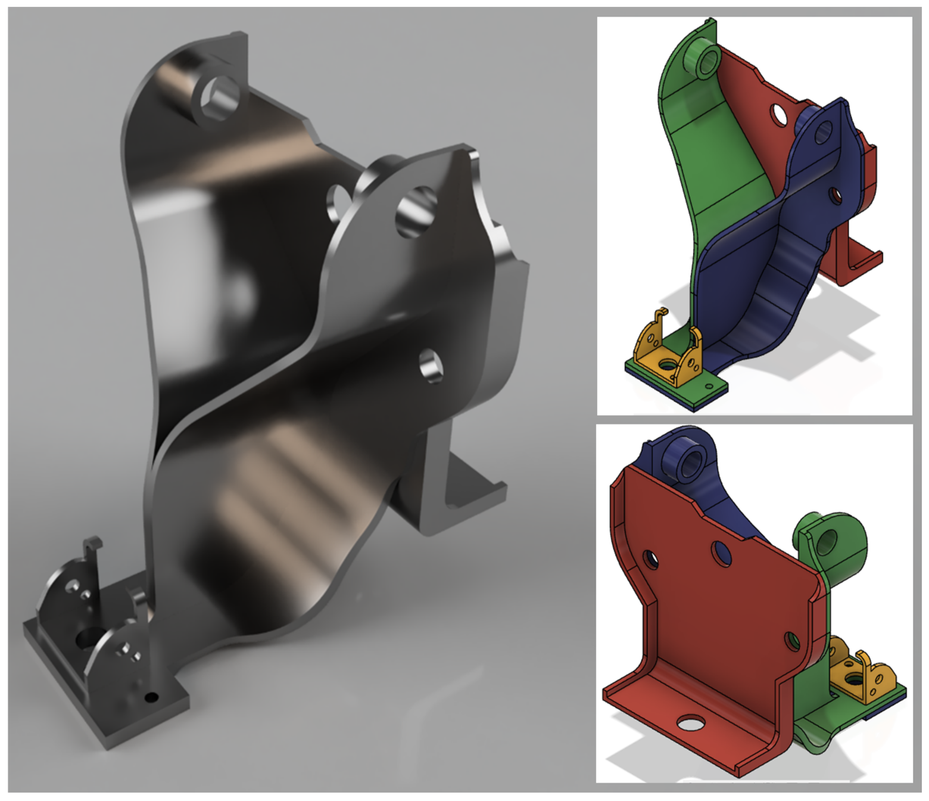
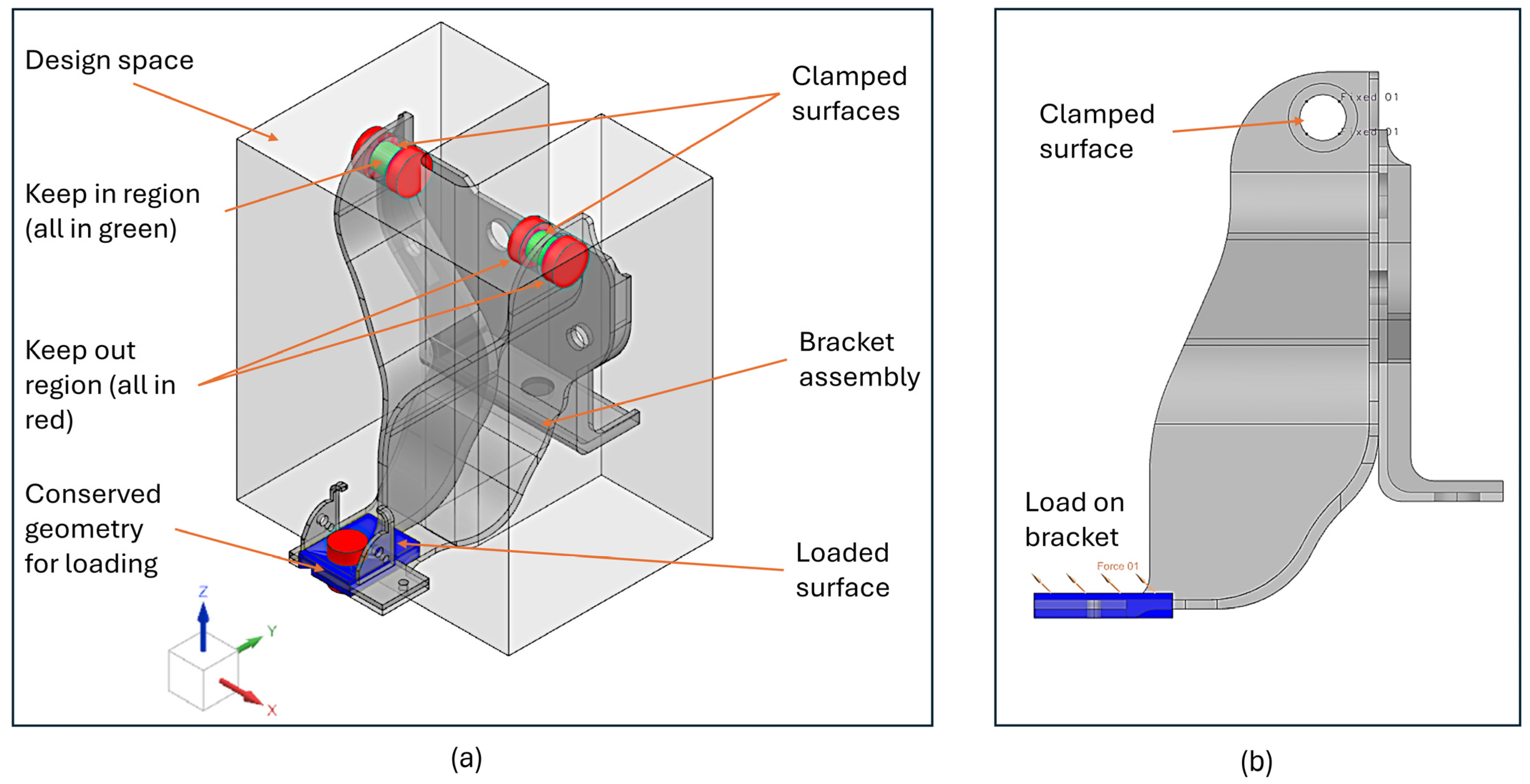
2.1. Assembly Geometry, Forces, and Material Properties

The initial step in formulating the problem involves the development of a three-dimensional model of the seatbelt bracket assembly. All four components of seat bracket assembly were designed and assembled using Siemens NX software (version 2206). Figure 1 details the assembly using different views. Distinct colors represent parts of the assembly. The overall length, width, and height of the assembly measure at 200, 200, and 240 mm, respectively, and the overall mass is 3.48 kg. The material used for the bracket assembly is steel 316, the physical properties of which are detailed in Table 1.
The load on the seatbelt bracket can be derived using measured vehicle deceleration at emergency braking or based on measured forces on the seatbelt during a crash. In the case of emergency braking, typical passenger car acceleration is −8.5 m/s2 at a vehicle speed of 80 km/h when the car is equipped with an anti-lock braking system (ABS) [16]. Therefore, the bracket loads can be calculated according to Newton’s second law of motion, as shown in Equation (1). Therefore, the maximum bracket load in the case of emergency braking and considering a passenger mass of 75 kg with two passengers’ seatbelts attached to the bracket and 8.5 m/s2 deceleration is 1250 N. According to statistics, in the case of crash, a vehicle’s frontal impact at a speed above 40 km/h would cause serious chest injuries for the seatbelt-restraint passenger [17]. For the case of a vehicle frontal impact at 40 km/h speed, the load on the seatbelt bracket was estimated on average to be 2000 N [17] when considering a passenger mass of 75 kg. Hence, the higher load of 2000 N was adopted for the topology optimization analysis.
F m a x = N   m p   a
where Fmax is the maximum load on the bracket, N is the number of passengers, mp is the mass of each passenger, and a is the acceleration of the vehicle.
For vibration analysis, the loads on the seatbelt generated by road roughness are transmitted through the car suspension system, chassis, and finally, the passenger’s seat to the passenger. Considering general car dynamic properties and vibration transmissibility, the maximum vibration acceleration was measured to be 2 m/s2 on the seat’s surface when road the international roughness index was 4.2 mm/m, car velocity was 70 km/h and using a Skoda Octavia car [18]. Other measured maximum vibration acceleration values reported in the literature for various laboratory testing conditions were 0.48 m/s2 [19] and 0.63 m/s2 [20]. In the most extreme case, according to the associated ISO standard [21], passengers would suffer extreme discomfort at a vibration acceleration of more than 2 m/s2. Using Equation (1) and considering the extreme case of 2 m/s2 vibration acceleration for a mass of two passengers (75 kg each), the load for vibration analysis is 300 N. The load was assumed to be cyclic with sin wave temporal behavior and an amplitude of 300 N. As metals are not extremely sensitive to frequency during fatigue testing, the frequency was not considered during the durability analysis.

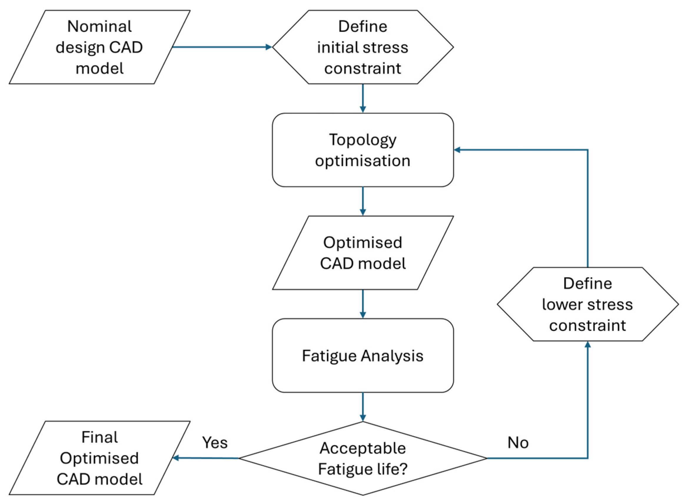
2.2. Finite Element Analysis and Topology Optimization

The solid isotropic material with penalization method (SIMP) is widely recognized as a prominent mathematical technique for topology optimization in the field of mathematics. SIMP is utilized to determine the optimal distribution of materials within a specified design space while considering numerous factors such as load cases, boundary conditions, manufacturing constraints, and performance requirements. In the conventional approach to topology optimization, the domain is discretized into a grid consisting of finite elements known as isotropic solid microstructures. These elements are either filled with material in regions where it is required or left empty in regions where material can be removed to represent voids. However, the SIMP method introduced a continuous relative density distribution function, which eliminated the traditional binary nature of this problem. This function allowed for a variation in relative density for each element, ranging from a minimum value to one, thereby enabling the assignment of intermediate densities. The inclusion of this relative density function ensured the numerical stability of the finite element analysis. Furthermore, as the material’s relative density can vary continuously, the material stiffness at each element can also vary continuously by incorporating a penalty factor, denoted as p. The penalty factor reduces the contribution of elements with intermediate densities to the overall stiffness. Numerical experiments have indicated that a penalty factor value of p = 3 is considered appropriate in practice [22].
For the optimization of the seatbelt bracket, various computer-aided engineering (CAE) tools were employed. The nominal design, which serves as a valid structure to be used as a starting point, was modeled using Siemens NX 2206 software. The nominal design underwent structural finite element analysis (FEA) using Siemens NX 2206 software to assess its static stress characteristics, including von Mises stress and maximum displacement. Then, using a topology optimization module within NX enabled the definition of an optimization problem, which is aimed at minimizing the mass of the assembly, which is constrained by the maximum stress limit and design space geometry and dimensions. The topology optimization mathematical model is depicted in Equations (2) and (3).
min ρ e M ρ e = ρ Ω ρ e   d Ω
s .   t . :     F = K ρ e   U ,   K ρ e = e = 1 n ρ m i n + 1 ρ m i n ρ e p K e   E ρ e = ρ e p   E 0   σ e = ( σ x x σ y y ) 2 + ( σ y y σ z z ) 2 + ( σ y y σ x x ) 2 + 6 ( τ x y 2 + τ x y 2 + τ x y 2 ) 2   σ m a x   , ρ m i n ρ e 1  
where M is the mass of the assembly within the design domain/volume Ω, ρe is the relative density of the element, ρ is the density of the material, F is the global force vector, U is the global displacement vector, K is the global stiffness matrix of the structure containing n total number of elements, ρmin is the minimum allowable relative density value for empty elements, Ke is the stiffness matrix of the element, p is a penalty factor that scales the contribution of elements with intermediate relative densities to the total stiffness, E is Young’s modulus of elasticity for element e, E0 is the material Young’s modulus of elasticity, σe is the equivalent Von-Mises stress of the e element, and σmax is maximum stress assigned as a constraint for topology optimization. σxx, σyy, σzz, τxy, τxz, and τyz are stress components for the element according to Cauchy’s stress tensor notation.
Several iterations were subsequently conducted on the design space in order to examine the modifications in design, and the process of topology optimization was repeated until convergence was reached in order to identify the most optimal solution globally. Subsequently, the fatigue life of the bracket was estimated by integrating the results from Siemens NX with the durability module. The research methodology, as depicted in Figure 2, illustrates the complete flow of the numerical analysis. Similar research methodology was used by Azad et al. [10] to optimize a medical waste shredder blade. The estimated lifespan of the bracket was predicted using the stress life (SN) approach and employing the Goodman model for the mean stress correction of the fatigue curve. If the estimated lifespan is lower than the desired target, then the topology optimization step is repeated under a lower maximum stress limit; otherwise, the result of the optimization is accepted as the optimal design.
The design space was defined based on the overall dimensions of the assembly, and regions to keep out of the design space and regions to conserve its geometry were defined within the design space. Figure 3 depicts the design space for topology optimization, where the green regions are keep-in regions and red regions are to be kept out.
A uniform load totaling 2000 N due to passenger inertia was applied on the loaded surface (as detailed in Figure 3) at an inclination angle of 45° to account for seatbelt buckle inclination. The model’s clamped/fixed surfaces are the inside of bolting bosses at the top of the bracket; see Figure 3. Analysis type, optimization objective and voxel/element size were set to structural (linear static), minimize mass and 2 mm respectively, within the topology optimization module in NX. The optimization constraint was set to limit maximum stress to various iteration values starting from 180 MPa (90% of yield strength) and down to the optimum value that satisfied the expected fatigue life in the subsequent durability/fatigue analysis; see Figure 2.
The NX durability wizard for fatigue analysis requires structural linear static analysis to be calculated beforehand, which was achieved using the NX design simulation module with a load of 300 N at 45° (YZ plane) to the loaded surface. The durability wizard fatigue life estimation was set to use stress life data within the NX material library.

3. Results and Discussion

The topology optimization model was solved, and then the fatigue life of optimized geometry was calculated. If the minimum fatigue life in the model was lower than one million cycles, then a new maximum stress constraint could be used to obtain a new optimized geometry that satisfied the fatigue life required. When the maximum stress constraint was set to 125 MPa, the optimized geometry satisfied the minimum fatigue life of one million cycles. Figure 4 depicts, from various viewpoints, the final resultant geometry of the topology optimization that satisfied the fatigue life needed. The final optimized geometry weight was 0.8 kg, which was 23% of the original bracket assembly mass (3.5 kg). Figure 5 shows convergence history of the mass and stress limit during topology optimization calculations. The model took 140 iterations to converge to the minimum possible mass, and the convergence rate significantly stabilized after 80 iterations. The computation time reached 15 min when using a PC equipped with a 2.2 GHz core-i9 processor and 32 GB RAM.
The mechanical response of the optimized geometry and the initial bracket assembly is shown in Figure 6 and Figure 7, respectively. Von-Mises’ stress was 21% lower for the optimized geometry compared to the original bracket, which indicates the quality of the algorithm to efficiently minimize the mass that holds the required stress limit. The highly stressed region for the bracket was around the fixing bosses at the top; therefore, the topology optimization algorithm was driven to reinforce this area with more material. This reinforcement technique managed to obtain a lower-stressed optimized model. Conversely, the deflection displacement was increased by 0.1 mm for the optimized geometry compared to bracket assembly, which can be attributed to the differences in geometry between both.
As detailed in the previous section, each optimized geometry was subsequently used in the durability analysis to check for fatigue life; if not satisfactory, the topology optimization was repeated with different stress constraints. The results of the NX durability analysis for the optimized geometry that satisfied the fatigue life required are depicted in Figure 8. Maximum Von Mises stress at the peak of the fatigue cycle reached 33 MPa near the loading surface, and this value was much lower than the yield stress of the material. The minimum number of duty cycles was one million cycles, with critical regions around the fixation bosses and near the loading surface at the bottom.

4. Conclusions

In the current research, topology optimization of a passenger car seatbelt bracket was carried out to satisfy the extreme loading and durability requirements. Loading on the bracket due to passenger acceleration in the case of frontal car impact was identified and derived. Additionally, dynamic loading due to passenger vibration acceleration while the car was running on rough road conditions was derived. The following points are given as follows:
  • The suggested methodology was effective to optimize the bracket assembly for the extreme loading and fatigue life required.
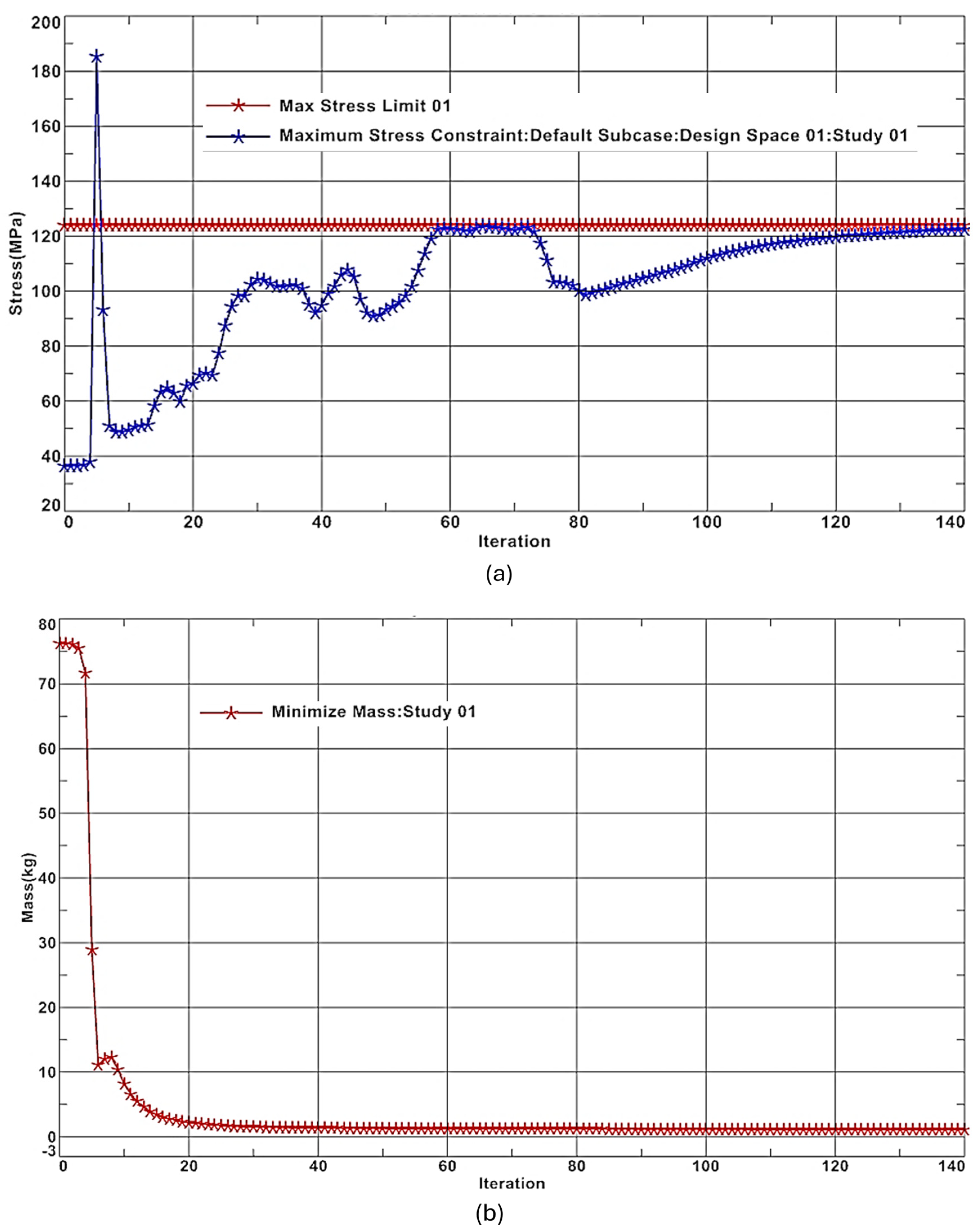
  • The optimization process took 140 iterations and showed convergence stability after 80 iterations. The optimized part mass was 77% lower compared to original bracket assembly.
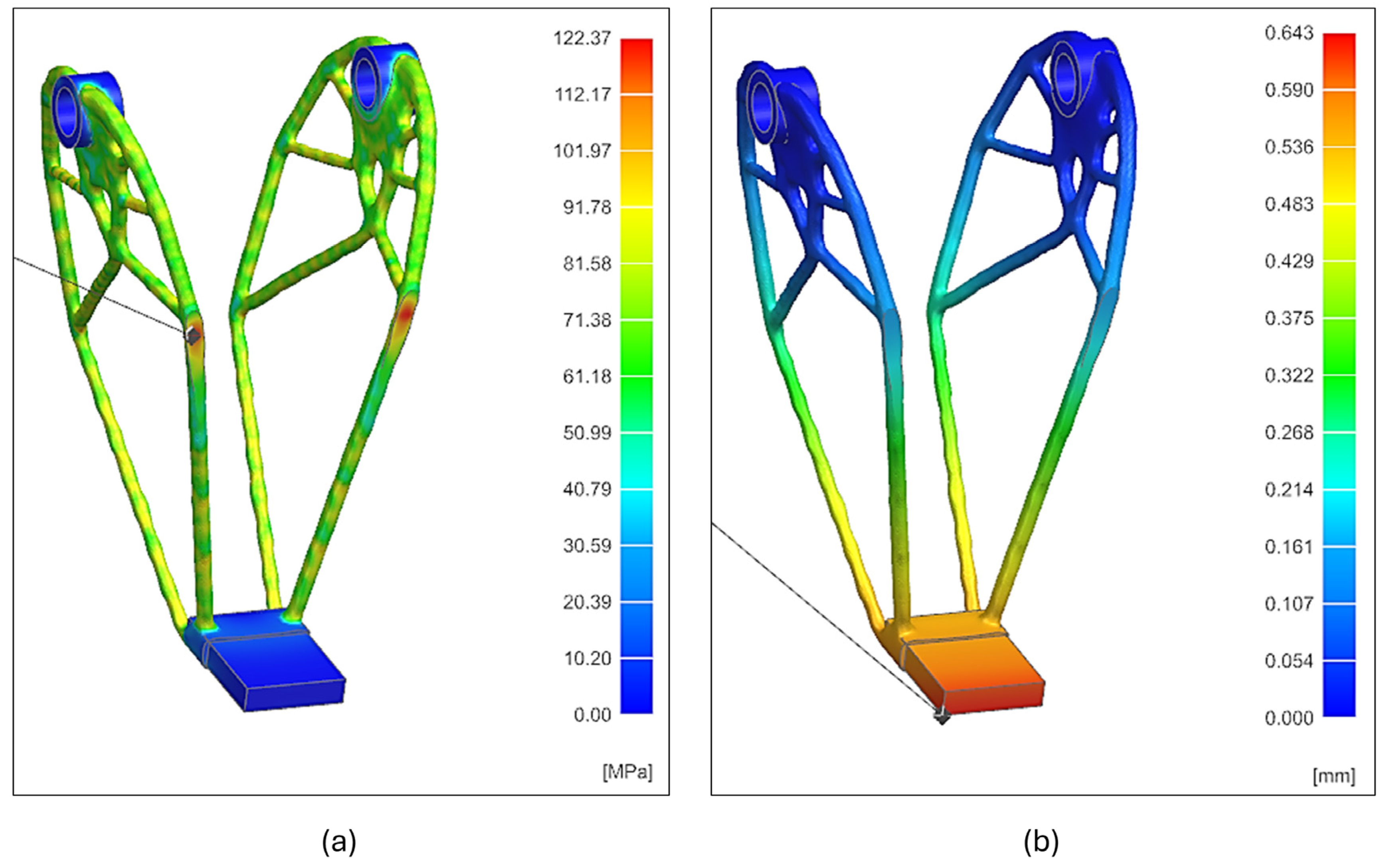
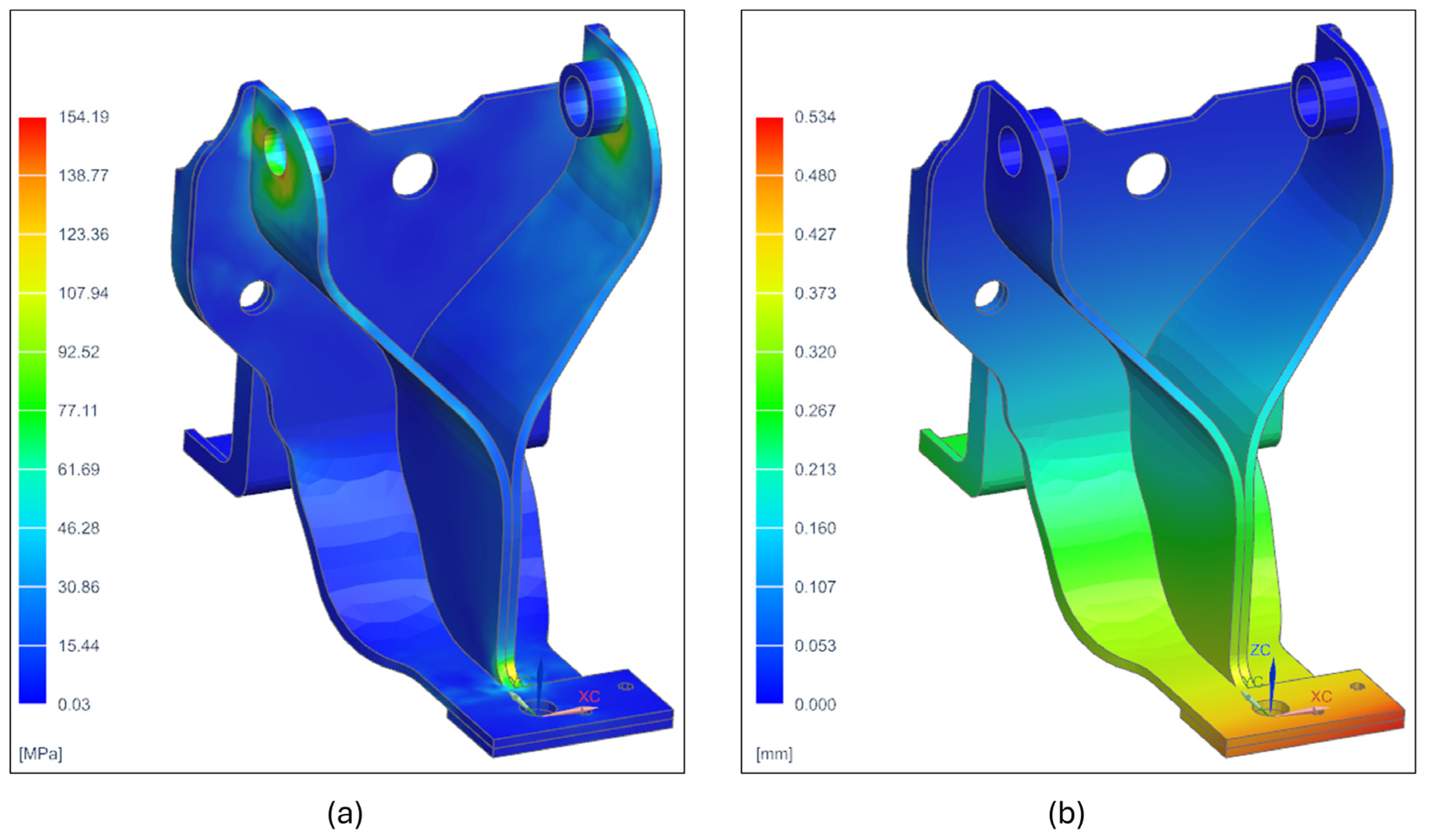
  • The optimized geometry achieved 21% lower maximum stress compared to bracket assembly.
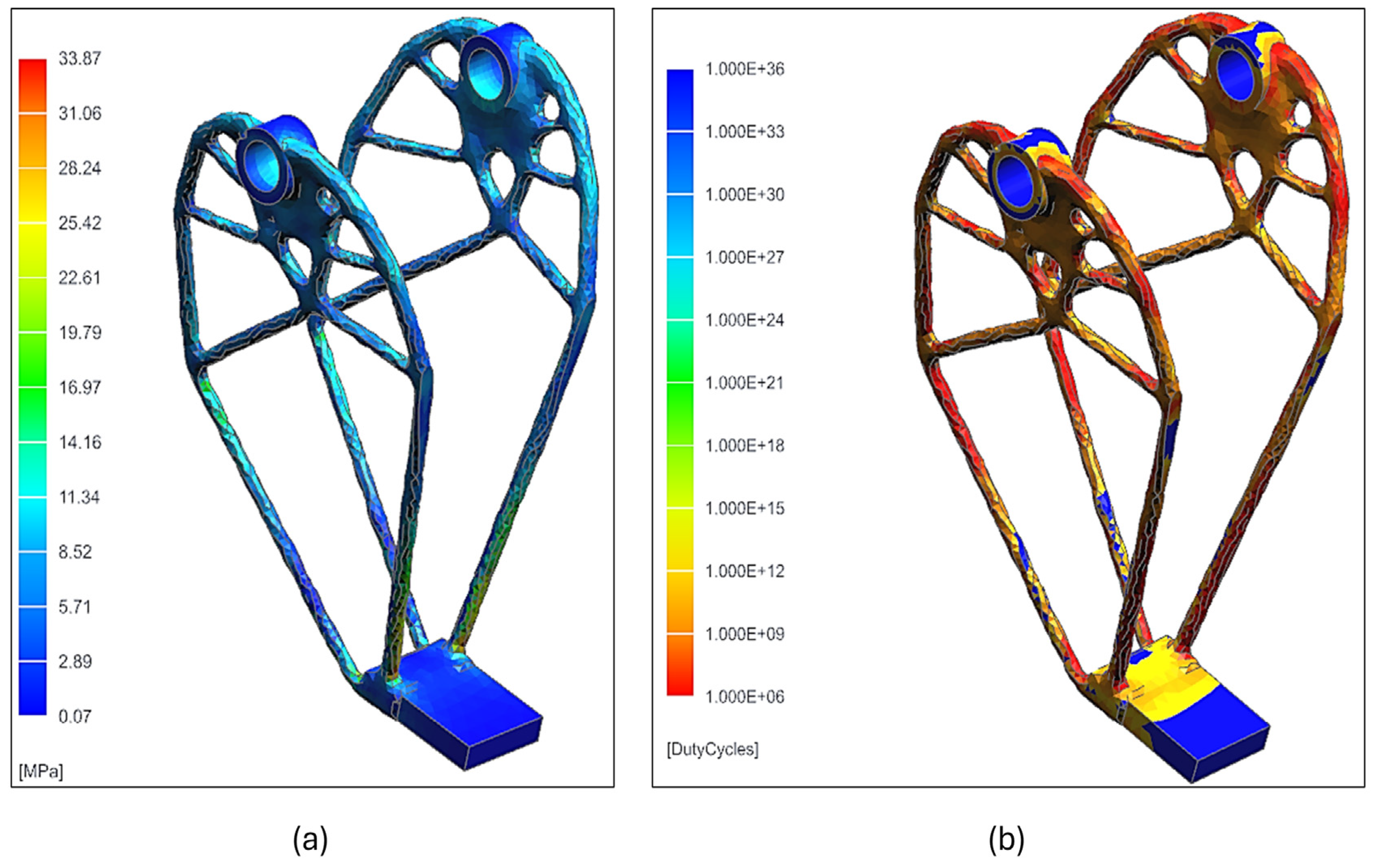
  • Maximum stress during durability analysis was 33 MPa, and the minimum number of duty cycles was estimated to be one million cycles.
  • The proposed design optimization scheme has proven computational efficiency due to its simplicity and use of standard commercially available solvers.

Author Contributions

Conceptualization, A.A.H. and B.B.; methodology, A.A.H.; software, A.A.H.; validation, A.A.H. and B.B.; formal analysis, A.A.H.; investigation, A.A.H.; resources, A.A.H.; data curation, B.B.; writing—original draft preparation, A.A.H.; writing—review and editing, A.A.H.; visualization, A.A.H.; supervision, A.A.H.; project administration, A.A.H. All authors have read and agreed to the published version of the manuscript.

Funding

This research received no external funding.

Data Availability Statement

The data are not available for the public as they are in use for further research.

Conflicts of Interest

The authors declare no conflicts of interest.

References

  1. Abdelhafeez, A.M.; Soo, S.L.; Aspinwall, D.K.; Dowson, A.; Arnold, D. The Influence of Burr Formation and Feed Rate on the Fatigue Life of Drilled Titanium and Aluminium Alloys Used in Aircraft Manufacture. CIRP Ann. 2018, 67, 103–108. [Google Scholar] [CrossRef]
  2. Holmberg, E.; Torstenfelt, B.; Klarbring, A. Fatigue Constrained Topology Optimization. Struct. Multidisc. Optim. 2014, 50, 207–219. [Google Scholar] [CrossRef]
  3. Oest, J.; Lund, E. Topology Optimization with Finite-Life Fatigue Constraints. Struct. Multidisc. Optim. 2017, 56, 1045–1059. [Google Scholar] [CrossRef]
  4. Guo, X.; Zhang, W.; Zhong, W. Doing Topology Optimization Explicitly and Geometrically—A New Moving Morphable Components Based Framework. J. Appl. Mech. 2014, 81, 081009. [Google Scholar] [CrossRef]
  5. Brighenti, R. Patch Repair Design Optimisation for Fracture and Fatigue Improvements of Cracked Plates. Int. J. Solids Struct. 2007, 44, 1115–1131. [Google Scholar] [CrossRef]
  6. Li, Y.; Zhou, G.; Chang, T.; Yang, L.; Wu, F. Topology Optimization with Aperiodic Load Fatigue Constraints Based on Bidirectional Evolutionary Structural Optimization. CMES 2021, 130, 499–511. [Google Scholar] [CrossRef]
  7. Boursier Niutta, C.; Tridello, A.; Paolino, D.S. Fatigue Design of Additive Manufacturing Components through Topology Optimization: Comparison of Methodologies Based on the Defect Distribution and on the Stress Gradient. Fatigue Fract. Eng. Mater. Struct. 2023, 46, 3429–3445. [Google Scholar] [CrossRef]
  8. Hou, J.; Zhu, J.; Wang, J.; Zhang, W. Topology Optimization of the Multi-Fasteners Jointed Structure Considering Fatigue Constraints. Int. J. Simul. Multidisci. Des. Optim. 2018, 9, A4. [Google Scholar] [CrossRef]
  9. Lee, Y.-S.; González, J.A.; Lee, J.H.; Kim, Y.I.; Park, K.C.; Han, S. Structural Topology Optimization of the Transition Piece for an Offshore Wind Turbine with Jacket Foundation. Renew. Energy 2016, 85, 1214–1225. [Google Scholar] [CrossRef]
  10. Azad, M.M.; Kim, D.; Khalid, S.; Kim, H.S. Topology Optimization and Fatigue Life Estimation of Sustainable Medical Waste Shredder Blade. Mathematics 2022, 10, 1863. [Google Scholar] [CrossRef]
  11. Ye, H.; Zhang, Y.; Wei, N.; Wang, W.; Xiao, Y. The Fatigue Topology Optimization of Orthotropic Materials. J. Phys. Conf. Ser. 2023, 2535, 012027. [Google Scholar] [CrossRef]
  12. Desmorat, B.; Desmorat, R. Topology optimization in damage governed low cycle fatigue. Comptes Rendus Mécanique 2008, 336, 448–453. [Google Scholar] [CrossRef]
  13. Nvss, S.; Esakki, B.; Yang, L.-J.; Udayagiri, C.; Vepa, K.S. Design and Development of Unibody Quadcopter Structure Using Optimization and Additive Manufacturing Techniques. Designs 2022, 6, 8. [Google Scholar] [CrossRef]
  14. Zhao, T.; Zhang, Y.; Ou, Y.; Ding, W.; Cheng, F. Fail-Safe Topology Optimization Considering Fatigue. Struct. Multidisc. Optim. 2023, 66, 132. [Google Scholar] [CrossRef]
  15. Jeong, S.H.; Lee, J.W.; Yoon, G.H.; Choi, D.H. Topology Optimization Considering the Fatigue Constraint of Variable Amplitude Load Based on the Equivalent Static Load Approach. Appl. Math. Model. 2018, 56, 626–647. [Google Scholar] [CrossRef]
  16. Kudarauskas, N. Analysis of Emergency Braking of a Vehicle. Transport 2007, 22, 154–159. [Google Scholar] [CrossRef]
  17. Xiao, S.; Yang, J.; Crandall, J.R. Investigation of Chest Injury Mechanism Caused by Different Seatbelt Loads in Frontal Impact. Acta Bioeng. Biomech. 2017, 19, 53–62. [Google Scholar] [CrossRef]
  18. Múčka, P. International Roughness Index Thresholds Based on Whole-Body Vibration in Passenger Cars. Transp. Res. Rec. 2021, 2675, 305–320. [Google Scholar] [CrossRef]
  19. Kumaresh, S.A.; Aladdin, M.F. A Study of Vibration Transmission on Seated Person in Passenger Vehicle. AIP Conf. Proc. 2019, 2137, 040001. [Google Scholar]
  20. Pan-Zagorski, W.; Johnson, P.W.; Pereny, M.; Kim, J.H. Automotive Seat Comfort and Vibration Performance Evaluation in Dynamic Settings. Appl. Sci. 2022, 12, 4033. [Google Scholar] [CrossRef]
  21. ISO 2631-1:1997; Mechanical Vibration and Shock—Evaluation of Human Exposure to Whole-Body Vibration. Part 1: General Requirements. International Organization for Standardization: Geneva, Switzerland, 1997. Available online: https://www.iso.org/standard/7612.html (accessed on 28 August 2024).
  22. Kaščak, J.; Gašpár, Š.; Paško, J.; Husár, J.; Knapčíková, L. Polylactic Acid and Its Cellulose Based Composite as a Significant Tool for the Production of Optimized Models Modified for Additive Manufacturing. Sustainability 2021, 13, 1256. [Google Scholar] [CrossRef]
Figure 1. Seatbelt bracket assembly CAD model of passenger’s back seat.
Designs 08 00099 g001
Figure 2. Flowchart of the procedure used for topology optimization considering fatigue.
Designs 08 00099 g002
Figure 3. (a) The design space for the topology optimization model. (b) The boundary conditions applied on the assembly.
Designs 08 00099 g003
Figure 4. Final geometry after topology optimization: (a) front view, (b) side view, (c) isometric view, and (d) final optimized geometry compared to original bracket assembly.
Designs 08 00099 g004
Figure 5. Convergence history of the topology optimization model calculations: (a) maximum stress limit; (b) mass of the model.
Designs 08 00099 g005
Figure 6. Response of the optimized geometry to a static load of 2000 N: (a) Von-Mises’ stress distribution; (b) resultant deflection displacement. The maximum value location is marked with a line.
Designs 08 00099 g006
Figure 7. Response of the initial bracket assembly to a static load of 2000 N: (a) Von-Mises’ stress distribution; (b) resultant deflection displacement.
Designs 08 00099 g007
Figure 8. (a) Stress distribution at the peak of the fatigue cycle (load of 300 N); (b) we expected no cycles to fail based on the durability analysis by NX.
Designs 08 00099 g008
Table 1. Steel 316 material properties.
PropertyValue
Density (kg/m3)7870
Modulus of elasticity (GPa)200
Poisson’s ratio0.27
Yield stress (MPa)200
Tensile strength (MPa)500
Endurance limit (MPa)260
Disclaimer/Publisher’s Note: The statements, opinions and data contained in all publications are solely those of the individual author(s) and contributor(s) and not of MDPI and/or the editor(s). MDPI and/or the editor(s) disclaim responsibility for any injury to people or property resulting from any ideas, methods, instructions or products referred to in the content.

