Article

Development of a Stress Block Model to Predict the Ultimate Bending Capacity of Rectangular Concrete-Filled Steel Tube Beams Strengthened with U-Shaped CFRP Sheets

1
Department of Civil Engineering, Universiti Kebangsaan Malaysia (UKM), Bangi 43600, Selangor, Malaysia
2
Civil Engineering Department, Al Turath University, Baghdad 10013, Iraq
3
Department of Civil Engineering, School of Engineering, University of Minho, Azure’m, 4810-058 Guimarães, Portugal
4
Center for Multidisciplinary Infrastructure Engineering, Shenyang University of Technology, Shenyang 110870, China
*
Author to whom correspondence should be addressed.
Infrastructures 2025, 10(4), 73; https://doi.org/10.3390/infrastructures10040073
Submission received: 1 February 2025 / Revised: 10 March 2025 / Accepted: 17 March 2025 / Published: 24 March 2025
(This article belongs to the Section Infrastructures and Structural Engineering)

Abstract

:
The prediction of the ultimate bending capacity of the rectangular concrete-filled steel tube (RCFST) beams strengthened with U-shaped carbon fiber reinforced polymer (CFRP) sheets is limited to using the existing empirical models. Thus, this study aims to develop a new theoretical model based on a stress block model to predict the ultimate bending capacity (Mu) of the RCFST beams strengthened with a U-shaped CFRP-wrapping scheme. For this purpose, 28 finite element (FE) models of CFRP-strengthened RCFST beams had been analyzed for further investigation of the flexural behavior and longitudinal stresses distributed along with the beam’s components (steel tube, concrete core, and CFRP layers). The main parameters investigated are concrete compressive strength, steel yield strength, number of CFRP layers, and CFRP-wrapping-depth ratio. In addition, the Mu values obtained from the FE models of the current study and those from the existing experimental tests performed by others are used to verify the corresponding values that are theoretically predicted by the new model. The comparison showed that the proposed model is moderately conservative, as the predicted values of Mu are, on average, up to 10% lower than those obtained from experimental tests and FE analysis.

1. Introduction

The application of carbon-fiber-reinforced polymers (CFRPs) for retrofitting and strengthening concrete-filled steel tube (CFST) members has been extensively investigated, as CFRP has numerous advantages, including fast application, application to fit any cross-section shape, lightweight, high strength, durable, and fatigue resistance. Experimental studies on CFST columns under different loadings have showed that wrapping circumferentially CFRP on whole or partial length of CFST columns can improve the load-carrying capacity of columns since wrapping CFRP enhances the concrete confinement [1,2]. On the other hand, applying CFRP circumferentially on CFST beams subjected to pure bending was found to not be very effective [3], while studies on longitudinally wrapping CFRP on CFST beams indicated a significant increase in the bending capacity of the CFST beams [4]. Moreover, wrapping CFRPs on the whole beam’s cross-section is not always applicable and practical, since the beams are usually supported by a slab/floor system from their top side [5]. Thus, the efficiency of applying CFRPs on the part of the beam’s cross-section in the longitudinal direction has been investigated.
To date, two partial CFRP-wrapping schemes, including flat wrapping and U-shaped wrapping schemes, have been proposed for CFST beams under pure bending. For an example of such studies on flat wrapping schemes, ref. [6] experimentally investigated the flexural behavior of square CFST beams strengthened with flat CFRP layers, which are applied along varied lengths on the bottom flange. The results indicated a 28.44% improvement in the ultimate bending capacity of the CFST specimens when strengthened with three CFRP layers. Later, ref. [7] compared the effect of flat wrapping and U-shaped wrapping schemes (applied along the bottom half of the beam’s cross-section) on the ultimate bending capacity of the square CFST beams under pure bending, which revealed the U-shaped wrapping scheme achieved better strengthening performance than the flat wrapping scheme. Additionally, several experimental and numerical studies on the CFST beams wrapped with the U-shaped CFRP scheme investigated the effects of varied wrapping schemes (longitudinal or a combination of longitudinal and transverse), number of longitudinal CFRP layers, CFRP-wrapping lengths (50%, 75%, and 100%), cross-section shapes (circular and rectangular), cross-section sizes, steel yield strengths, and concrete strengths [5,8,9,10]. In general, these investigations revealed that the U-shaped wrapping is very effective, specifically when applied along a sufficient length to avoid debonding failure of the CFRP patch from the steel tube. Moreover, it was found that the U-shaped wrapping scheme is as efficient as the fully wrapping scheme when used for strengthening the simply supported rectangular CFST specimen [9].
Despite the numerous investigations on the CFRP-strengthened CFST beams, there is a lack of studies to theoretically predict the ultimate bending capacity of these strengthened and/or repaired beams. Generally, the ultimate bending capacity of the CFST beams can be predicted based on stress block models provided by international building codes [11,12,13] and other theoretical models developed by researchers [14,15]. To date, no theoretical model based on stress block models has been developed to predict the ultimate bending capacity of CFRP-strengthened CFST beams. As a result, the prediction of the ultimate bending capacity for such beams is currently limited to empirical models. These models were developed by [16] for fully wrapped schemes and by [9] for U-shaped wrapping schemes.
According to the gap established in the above literature, the main aim of this research is to develop a new theoretical model based on the stress block model for predicting the ultimate bending capacity of the CFST beams that are partially wrapped with multi-layers of CFRP sheets. Particularly, this study is limited to the CFST beams with rectangular cross-sections and uses a U-shaped CFRP-wrapping scheme (U-CFRP-RCFST), since this is the most practical beam cross-section and wrapping scheme that can be used in the construction field. In addition, this model is expected to give practical support to the engineers for selecting the most proper and economical CFRP-strengthening solution for this type of composite member (RCFST members under pure bending). Proposing stress block models for the components of the composite beam requires a deep investigation on the influence of the different parameters on the stress distribution in the composite beam section under pure flexural loading. In previous studies, it has been proven that finite element (FE) modeling is able to simulate accurately the structural behavior of steel, reinforced concrete, and composite members under various loadings [17,18,19,20]. Thus, in this study, 28 FE models of U-CFRP-RCFST beams were developed and analyzed via ABAQUS/Standard to investigate the effect of various parameters, such as concrete compressive strength, steel yield strength, number of CFRP layers, and wrapping-depth of the U-shaped CFRP on the flexural behavior and stress distribution of U-CFRP-RCFST. Then, the new theoretical model is developed based on the proposed block stress models to predict the ultimate bending capacity of the U-CFRP-RCFST beams, whose validity is verified by the results obtained from the analyses of current FE models and those experimentally tested by others.

2. Finite Element Modeling

The behavior of the CFRP-strengthened CFST beams under four-point loads is currently investigated by 3D nonlinear FE models. ABAQUS/Standard was utilized in this study to develop and analyze these models. To gain the nonlinear behavior of the models, geometry and material nonlinearity were employed. The specifications of the models, such as dimensions, material properties, number of CFRP layers, and boundary conditions are adopted from previous experimental studies [8,9]. Table 1 presents the specifications of the models that are used to verify the current FE analysis method. The schematic loading scenario of the studied FE models adopted in this study is shown in Figure 1.

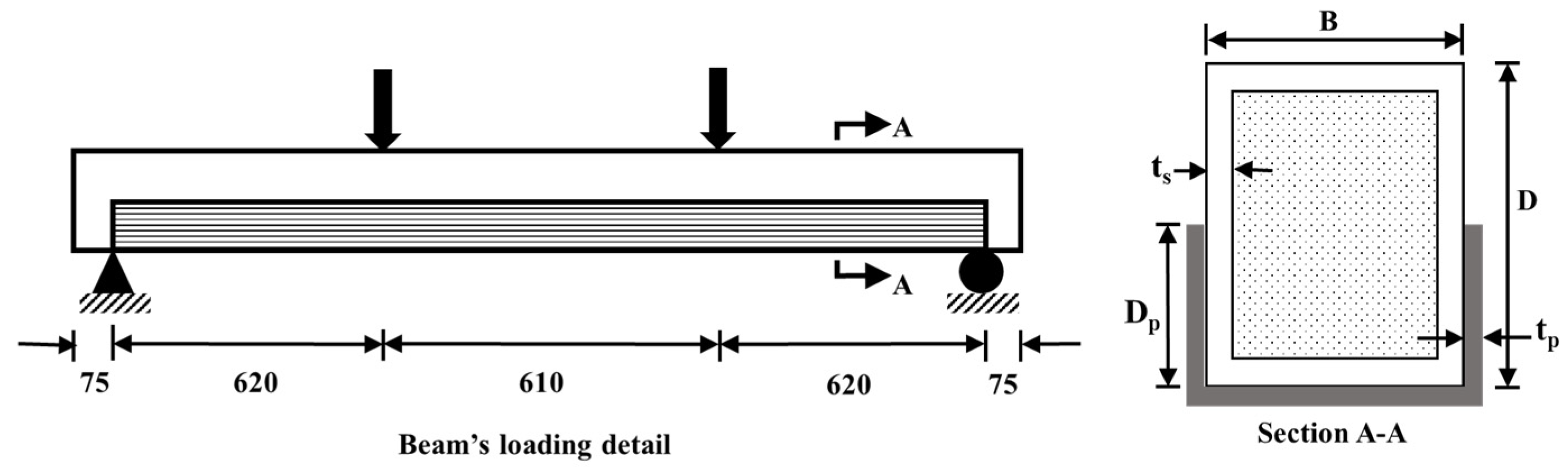
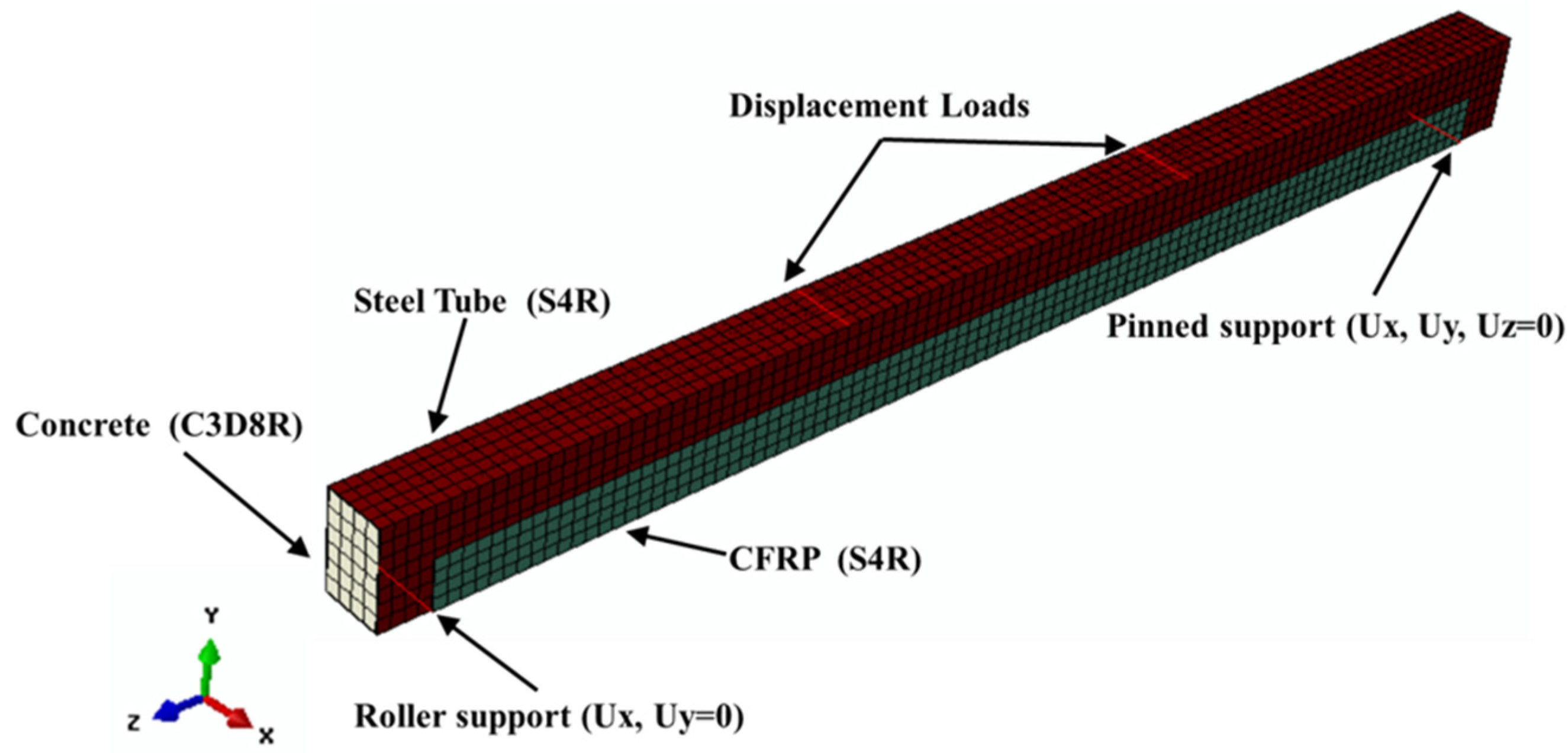
2.1. Boundary Conditions and Element Description

The typical boundary conditions of the suggested FE models and the assigned elements to the 3D FE models’ components are illustrated in Figure 2. To simulate the actual testing scenario of the rectangular CFST beam, the subjected two-point loads were simulated using two displacement loads that were applied to the node sets on the top flange of the steel tube. The translations in all directions (X, Y, and Z) were restricted in a node-set at the bottom of the steel tube (bottom flange) to model the pinned support. Meanwhile, the roller support was modeled by restricting the translation of a node-set in X- and Y-directions only and kept the beam with free movement along the Z direction. In addition, the elements available in ABAQUS/Standard were used to model the CFST beams’ components, including 8-node solid elements, with reduced integration (C3D8R), which was selected to model the infilled concrete [9]. In addition, the steel tube and CFRP layers were modeled using a shell element known as “S4R”, which is available with four-node and reduced integration [8]. The optimum mesh size of the elements was gained from a sensitivity analysis, which was 25 mm for the concrete and 20 mm for the steel and the CFRP sheets.

2.2. Surface Interaction

The interaction between the inner surface of the steel tube and the outer surface of infilled concrete is defined by the node-to-surface contact [21]. Hard contact in the normal direction and penalty mode with a coefficient of 0.75 in the tangential direction, which were adopted from [5], was used for their contact properties. Furthermore, the steel tube and CFRP patch were tied, since the corresponding experimental test results revealed that the primary failure mode of the U-CFRP-RCFST beams was CFRP rupture and there was no CFRP debonding failure before the peak load [5]. In case U-shaped CFRP was applied on the whole length of the CFST beams, the CFRP debonding may happen at the end of loading due the excessive deflection of the composite beam, which is not a critical focus of this study. Thus, considering tie contact between the CFRP and the steel tube does not affect the accuracy of the pre-peak load behavior of U-CFRP-CFST beams, as also confirmed previously in other similar FE studies on CFRP-strengthened CFST beams [5,9].

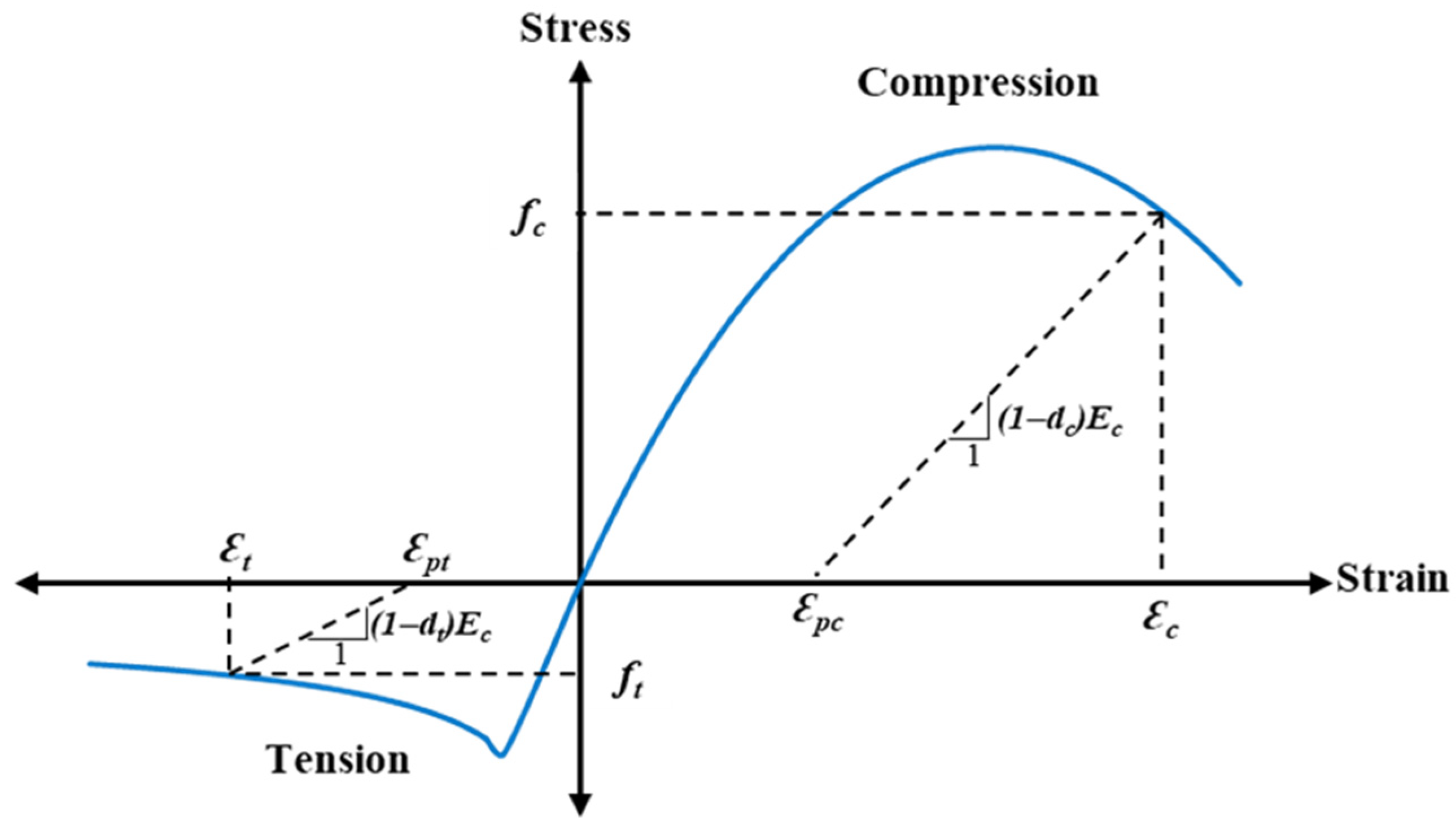
2.3. Material Properties and Modeling

To accurately simulate the behavior of the steel material of the FE models, a similar bilinear stress–strain relationship for both compressive and tensile stresses was adopted, as used earlier in previous similar numerical studies [21]. The elastic range of the stress–strain relationship of steel was simulated using the isotropic–elastic option in ABAQUS/Standard by defining the modulus of elasticity and Poisson’s ratio. Meanwhile, the plastic range was modeled using isotropic hardening by defining the true yield strength and the true plastic strain of the steel tubes, which are determined from Equations (1) and (2). Table 2 presents the tested steel properties adopted from experimental studies [8,9].
σ t u r e = σ e n g 1 + ε e n g
ε t u r e = ln 1 + ε e n g
In the elastic range, concrete behaves like an isotropic–elastic material up to 0.45 f′c and fcr in compression and tension, respectively [22]. The elastic behavior of concrete was simulated using the isotropic–elastic option model available in ABAQUS/Standard. Meanwhile, the concrete damage plasticity “CDP” was employed for the concrete at the plastic range to resemble the crushing and cracking behavior under tension and compression stresses, respectively. Figure 3 demonstrates the typical strength-strain relationship of concrete material.
The stress–strain relationships of the concrete in compression and tension were adopted from the models developed by [23] and Wang and Hsu [24], respectively, which are expressed as follows:
f c = k n k n 2 1 + ( k 2 ) n f c m
k = 1.05 E c ε 0 f c m
n = ε c ε 0
E c = 22000 ( f c m / 10 ) 0.3
f c m = f c + 8
f t = E c ε t : ε t ε c r f c r ε c r ε t 0.4 : ε t > ε c r
f c r = 0.31 f c
ε c r = f c r E c
The CDP parameters were acquired from [21] as presented in Table 3. Moreover, the tensile and compressive damage parameters were determined from Equations (11) and (12), and the tensile and compressive stiffness recovery factors were taken as 0 and 1 (default values), respectively [25].
d t = 1 f t E c ε t ε p t
d c = 1 f c E c ε c ε p c
The behavior of unidirectional CFRP sheets is orthotropic linear elastic, where the plastic range of the CFRP sheets is not considered [5]. Thus, the linear stress–strain relationship of the CFRP sheets was modeled using the lamina elastic option [25], which is able to model different elastic properties for each orientation of an orthotropic material. Moreover, the strength and damage criteria of the CFRPs were defined using the Hashin damage option [9]. To simplify the modeling and save analysis time, the multi-CFRP layers and the adhesive layers in between were converted to an equivalent single layer using the patch technique [26,27]. This technique assumes that all the layers of CFRP and the adhesive have same strain and the force of CFRP patch equals the summation of the forces of the CFRPs and the adhesive layers, much similar to the previous numerical investigation studies [5,9]. The thickness (tp), modulus of elasticity (Ep), and tensile strength of CFRP patch (fp) are determined as follows:
t p = n t C F   + ( n 1 ) t a
E p = n t C F E C F + ( n 1 ) t a E a t p
f p = n t C F f C F + ( n 1 ) t a f a t p
tCF, ECF, fCF, Ea, and fa equal to 0.129 mm, 228 GPa, 3224 MPa, 4.5 GPa, and 30 MPa, respectively, as adopted from the previous experimental studies [8,9]. The thickness of adhesive was taken as 0.8 mm [9].
To define the elastic properties of the CFRP patch in the lamina option, the elastic modulus in the longitudinal direction was calculated using Equation (14). The remaining parameters, including the elastic modulus in the transverse direction, Poisson’s ratio, and the shear modulus in different directions, were adopted from [28,29]. Additionally, the transverse tensile strength, longitudinal and transverse compressive strength, and longitudinal and transverse shear strength of the CFRP patch were defined in the Hashin damage option, based on the values recommended by [28,29]. The longitudinal tensile strength of the CFRP patch, however, was determined using Equation (15).
It is important to note that the longitudinal elastic modulus and longitudinal tensile strength of the CFRP patch had a significantly greater influence on the flexural behavior of the U-CFRP-CFST beam compared to the other parameters defined in the lamina and Hashin damage options. This is because the CFRP patch in the composite beam was primarily subjected to tensile forces in the longitudinal direction, and tensile rupture at the bottom flange of the composite beam was the dominant failure mode of the CFRP patch [5,8,9].

2.4. FE Models Verification

The accuracy of FE analysis results of the rectangular CFST models strengthened with CFRP sheets are verified with the experimental results of corresponding tested specimens [8,9], given earlier in Table 1. Figure 4 compares the moment–curvature curves at the mid-span of the FE models with those obtained from experimental tests [8,9]. Where the moment–curvature curves obtained from FE analysis are fairly agreed with the flexural behavior of the corresponding tested specimens. The differences between the ultimate bending moment values of the FE models (MFE) and the related experimentally tested specimens (MEx) ranged approximately from −5% to 4%. The MFE/MEx ratios achieved mean value (MV) and standard deviation (SD) equal to 1.00 and 0.04, respectively, which are within the acceptable deviation range (see Table 1).
Furthermore, the failure mode of the analyzed FE models of U-CFRP-RCFST beams reasonably confirmed the actual failures that were recorded for the corresponding tested specimens, as compared in Figure 5. Thus, the suggested FE model in the current study can appropriately simulate the flexural strength and behavior of the RCFST and U-CFRP-RCFST beams.

3. Parametric Study

After confirming the validity of the suggested FE-modeling concept, 28 models are further built for investigating the effects of varied CFRP layers, concrete compressive strength, steel tensile yield strength, and CFRP-wrapping-depth ratio on the flexural performance of the U-CFRP-RCFST beams have been investigated in this section, where the η value was the ratio of CFRP patch depth to the depth of the steel tube, in percentage. Table 4 presents the specifications of these FE models, including their ultimate bending moment obtained from the FE analysis and the corresponding theoretically predicted values. Generally, the effect of two different rectangular steel tube cross-section sizes was studied (sections given in Table 2).
The FE models are labeled in a way to address their properties. The labels start with “RS” or “R”, which represent the steel section sizes of 125 × 75 × 2.8 mm or 150 × 100 × 3.7 mm, respectively. After “RS” or “R”, the steel yield strength of 444/445.6, 355, 275, and 235 MPa are denoted by the letters “a” to “d”, respectively. Following these letters are the numbers corresponding to the concrete compressive strength (MPa), the number of CFRP layers, and the wrapping-depth ratio, respectively. For example, RSa-25-2-50 represents the model with the steel section size of 125 × 75 × 2.8 mm “RS”, fy = 445.6 MPa “a”, fcu = 25 MPa “fcu”, 2 CFRP layers “n”, and 50% CFRP-wrapping-depth “η”, respectively. It should be noted that the last two numbers related to n and η are omitted for the models without CFRP wrapping. The typical rectangular CFST models with varied CFRP-wrapping-depth are shown in Figure 6.

4. Results and Discussion

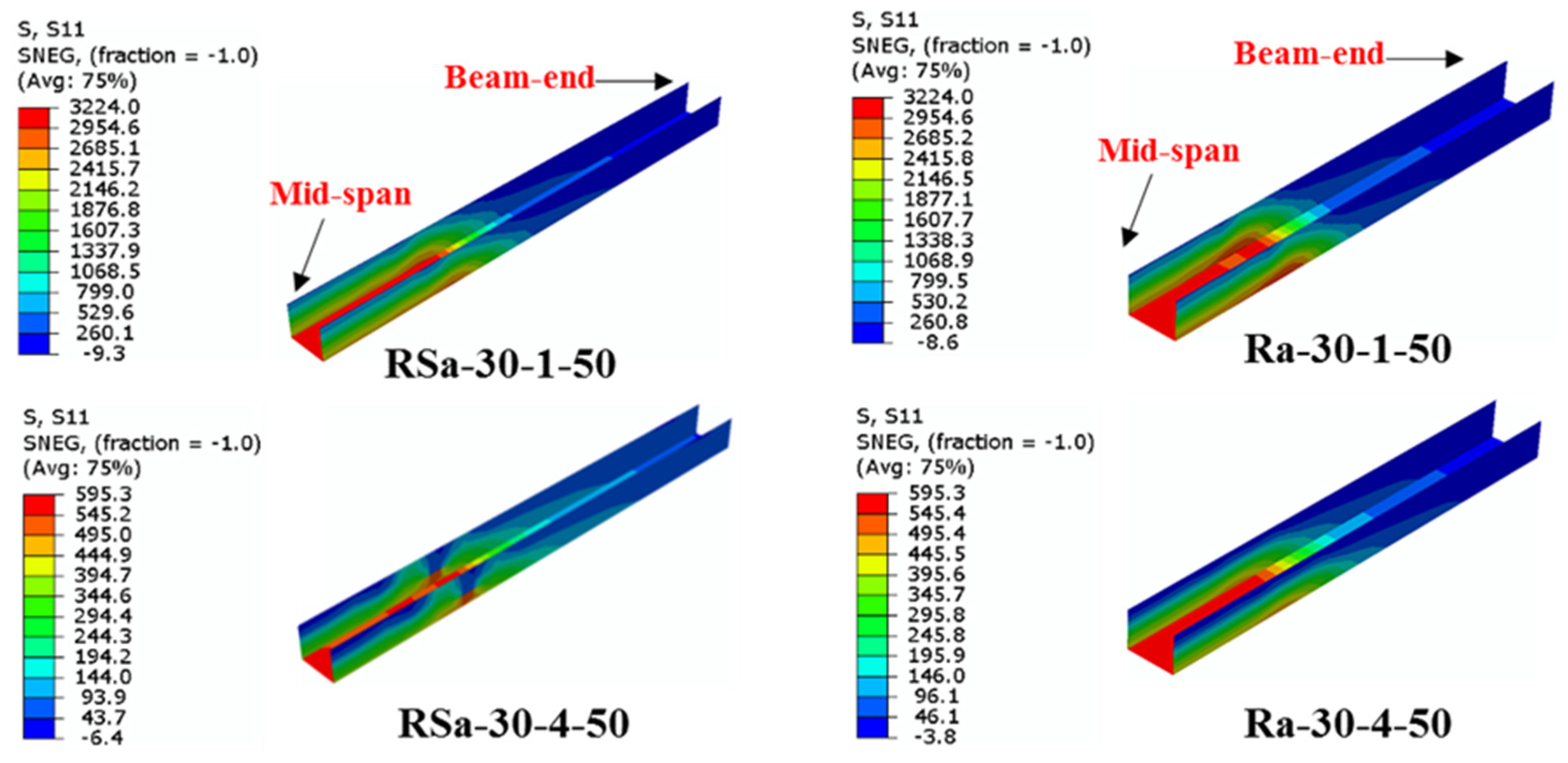
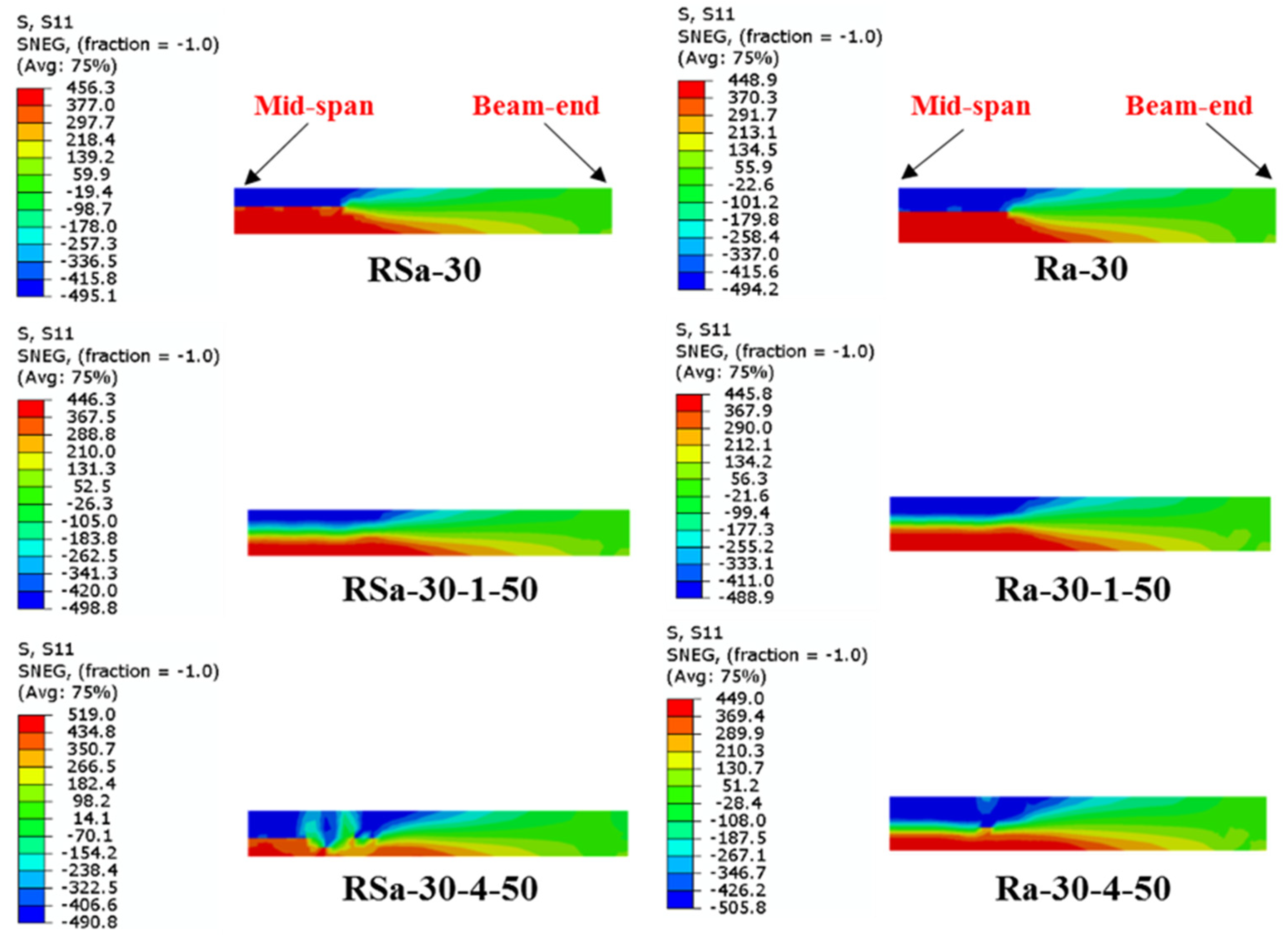
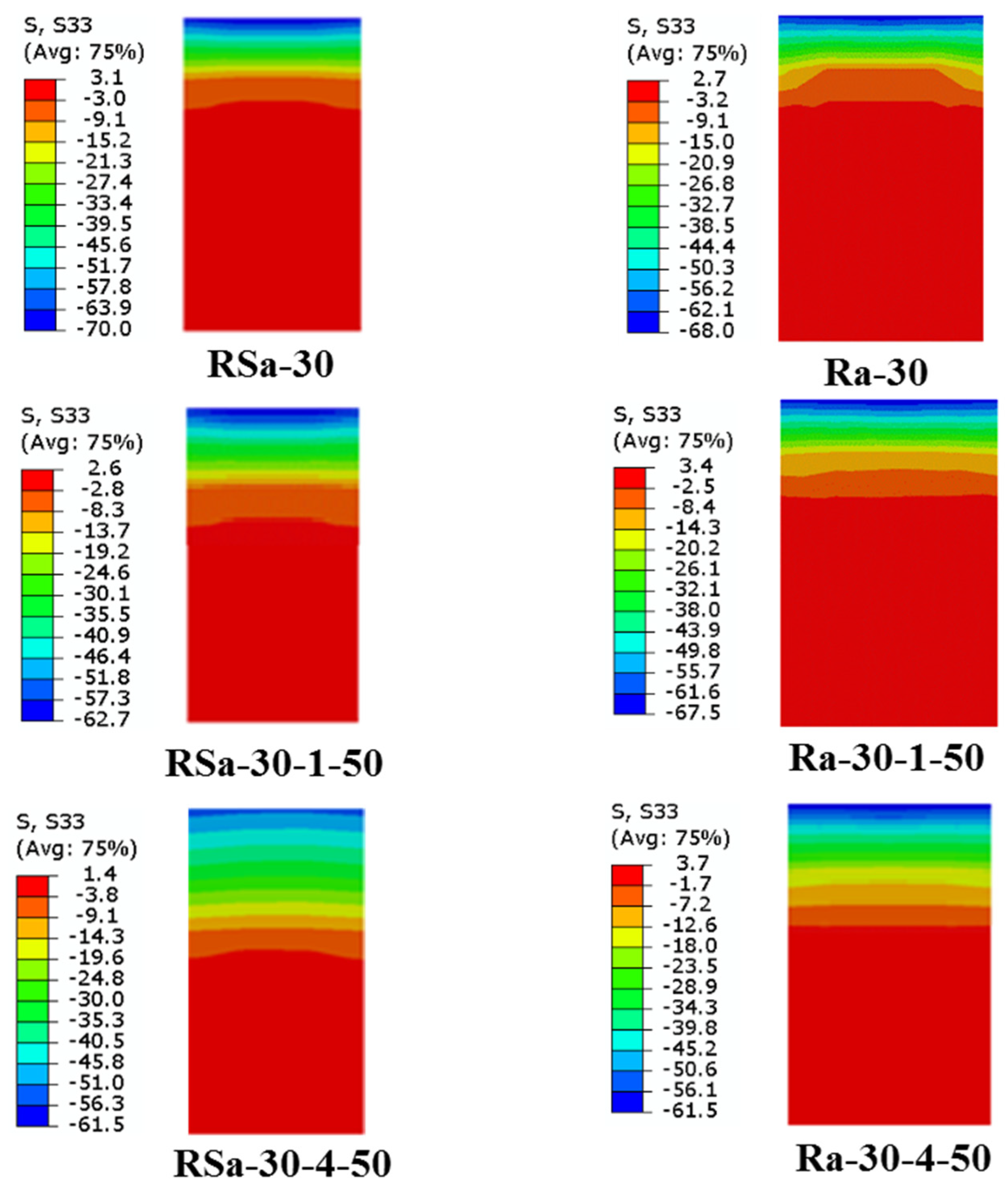
4.1. Effect of CFRP Layers

The effect of CFRP layers on the strengthening performance of RCFST models in terms of ultimate bending capacity and longitudinal stress distribution is presented and discussed in this section. Eight (8) RCFST models were analyzed to study the influence of using one to four CFRP layers, which compared all to their corresponding control RCFST models (RS and R), while all other parameters remained without change. The moment versus curvature relationship of the CFST models with tube sizes named “RS” and “R” are compared independently to their CFRP-strengthened CFST models in Figure 7. The MFE values achieved by these models are presented in Table 4, indicating that the ultimate bending capacities of U-CFRP-RCFST beams were increased with increasing CFRP layers, and the highest value was achieved when using four CFRP layers. As an example, RSa-30-4-50 and Ra-30-4-50 achieved about a 42.7% and 40.3% improvement in their ultimate bending capacities compared to their corresponding control models (RSa-30 and Ra-30).
The longitudinal stress distribution along the half-length of the U-shaped CFRP patch that was used for strengthening the RCFST models is shown in Figure 8, as an example. The maximum stress at the bottom flange gradually decreased toward the compressive stress at the tips of the webs, particularly at the distance located between the two-point loads (mid-span to the nearest loading point). The highest tensile stresses recorded on the CFRP patch were located at the extreme point at the bottom flange (mid-span), which confirmed the actual behavior of the CFRP material since it was fractured at this location once reached its ultimate tensile stress [8,9]. Meanwhile, the tensile stress (at mid-span) was reduced gradually when moved upward to the mid-depth of U-CFRP-RCFST models.
Figure 9 indicates the longitudinal stress distribution in the steel tubes. Both steel tubes of the reference models acted fully plastic at the mid-span. The stress analysis in the models with CFRP wrapping showed the middle part of the webs did not reach their yield stress as a result of the early fracture of CFRP patch in the tensile flange since the CFRP fracture strain is lower compared to the ultimate strain of the steel. The brittle fracture of CFRP was the reason for a sudden loss in the flexural strength of the strengthened CFST beams (as indicated earlier in Figure 7). The same brittle behavior was recorded in the experimentally tested specimens [5,8,9].
Figure 10 shows the longitudinal stress distribution in the cross-section of the concrete of the models with different layers of CFRP at the mid span. The longitudinal stress analysis at the mid span of the cross-section shows that the maximum compressive stress of the concrete occurs under the top flange of steel tube and also extensively exceeds the concrete compressive strength. This is attributed to the confinement effect provided by the steel tube, which remain without local buckling at the ultimate moment of the FE models. In addition, the high tensile force of the multi layers CFRP patch shifted the neutral axis toward the bottom of the section, which leads to a larger compressive area of the concrete core for the CFRP-strengthened models compared to the reference models.

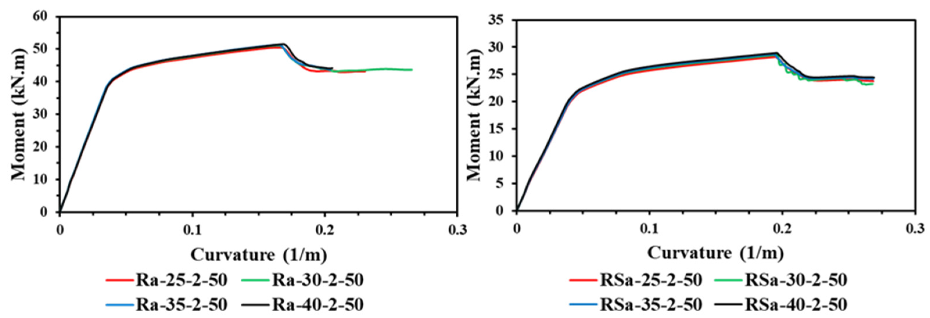
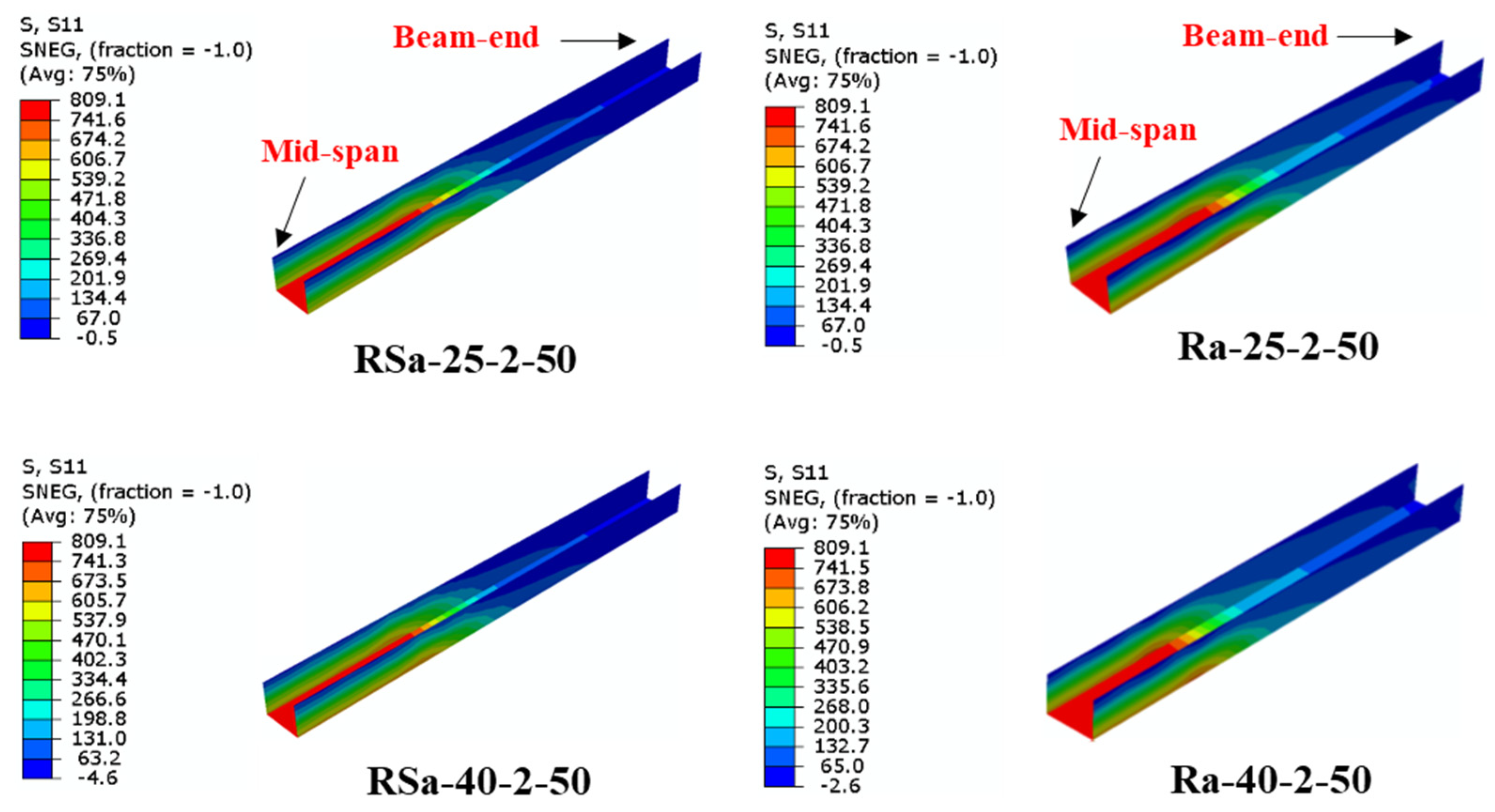
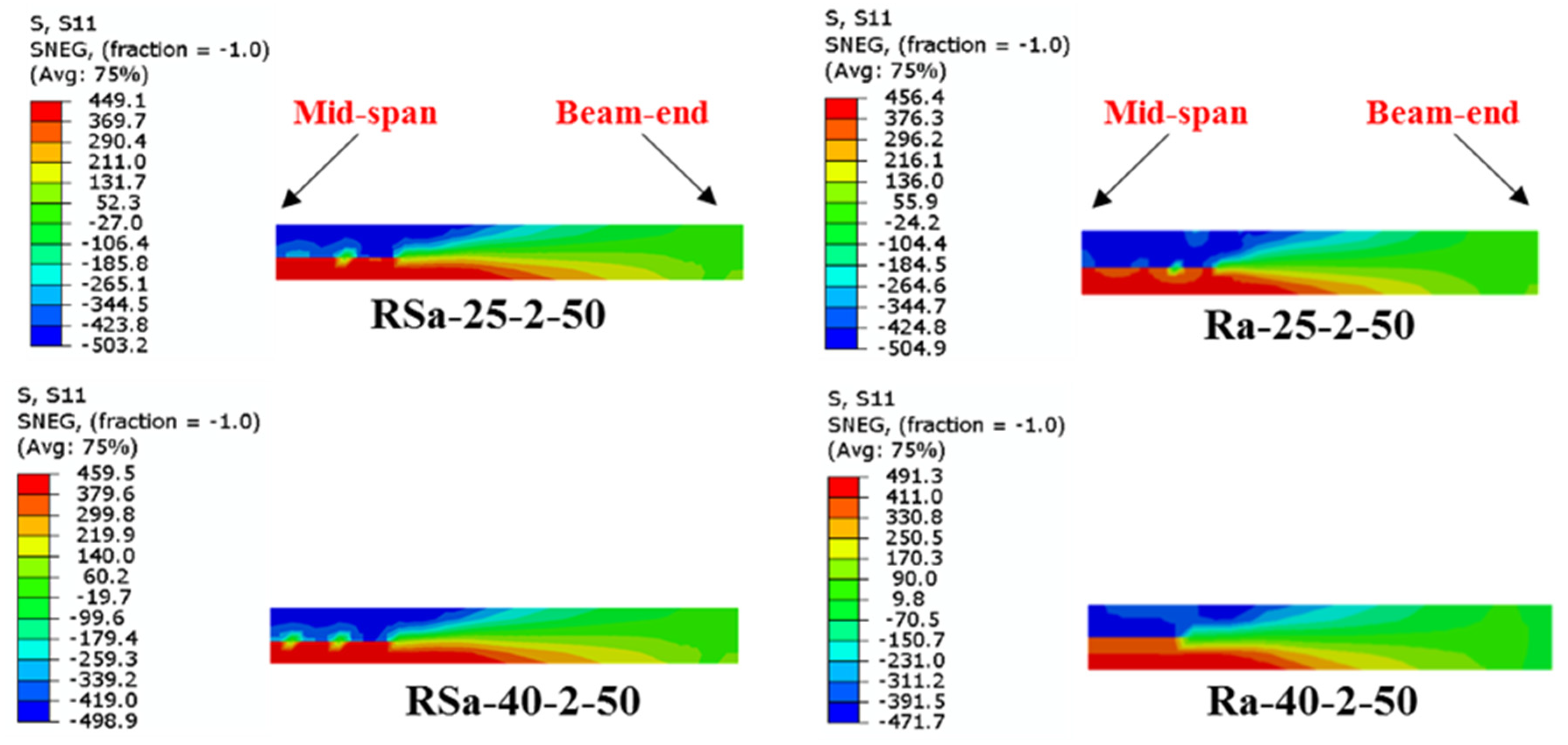
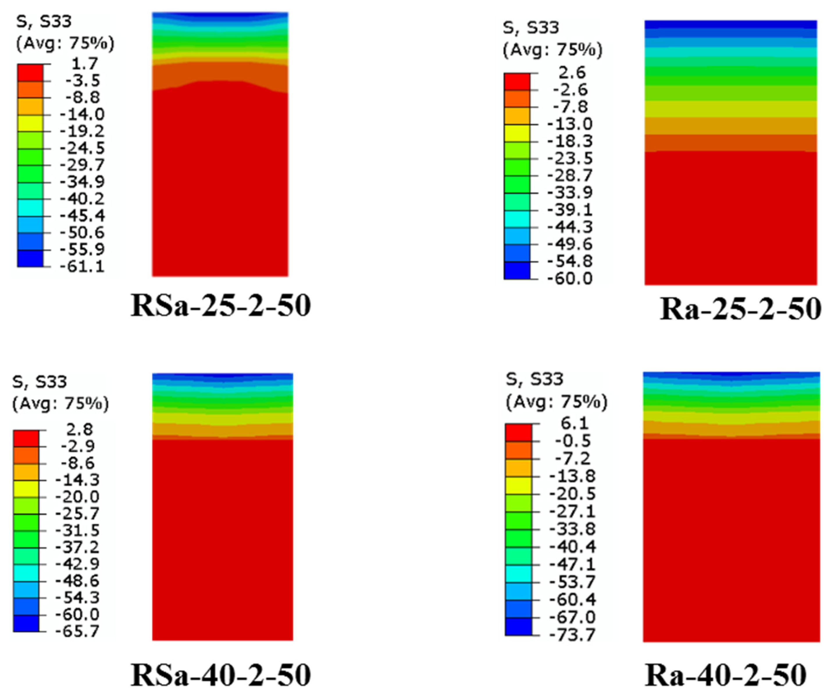
4.2. Effect of Concrete Compressive Strength

Figure 11 depicts the moment–curvature relationships of the models with varying concrete strengths (25 MPa to 40 MPa) at the mid-span. This figure confirmed that increasing the concrete strength showed a very minor impact on the U-CFRP-RCFST models regardless of the size of tube size (RS and R). This is probably due to the steel tube sections used in the analyzed FE models being classified as compact sections, where increasing the concrete strength usually showed a slight improvement in such CFST beam’s capacity. For example, the ultimate bending capacities of RSa-40-2-50 and Ra-40-2-50 are only 2.5% and 2% greater than those of RSa-25-2-50 and Ra-25-2-50, respectively (see Table 4). Similar performance was recorded in the existing studies where minimal differences in the ultimate bending capacity of CFRP-strengthened CFST beams due to the effects of varied infill concrete strengths [16].
The effects of the concrete strengths on the longitudinal stresses distributed along the CFRP patch of the strengthened RCFST models are presented in Figure 12. The stresses in the CFRP patch webs experienced a slight reduction as the concrete compressive strength increased. This occurred because of the shift in the neutral axis, caused by the increase in internal compressive force, led to an alteration in the stress distribution. However, this neutral axis movement is very limited and was not affected much by the tensile stresses distributed in the webs of these CFRP patches.
Figure 13 illustrates the changes in the longitudinal stresses of steel tubes due to the effects of varied concrete compressive strengths. This figure shows that increasing the concrete strength can slightly reduce the entire tensile stress at the bottom flange of the steel tube. However, this reduction has no noticeable effect on the plastic moment capacity of the steel tube as the majority of the steel tubes’ webs reached the yield stress.
The longitudinal stress distribution in the cross-section of the concrete core of the RCFST models with various compressive strengths at the mid-span is plotted in Figure 14. It can be seen that the maximum compressive stress of the concrete is increased by increasing the concrete strength. For example, the maximum compressive stress of RSa-40-2-50 and Ra-40-2-50 are 7.5% and 22.8% greater than RSa-25-2-50 and Ra-25-2-50. On the other hand, the compressive area is slightly decreased by increasing the concrete compressive strength, which indicates that increasing concrete strength is not much effective in improving the ultimate bending capacity of the U-CFRP-RCFST beams.

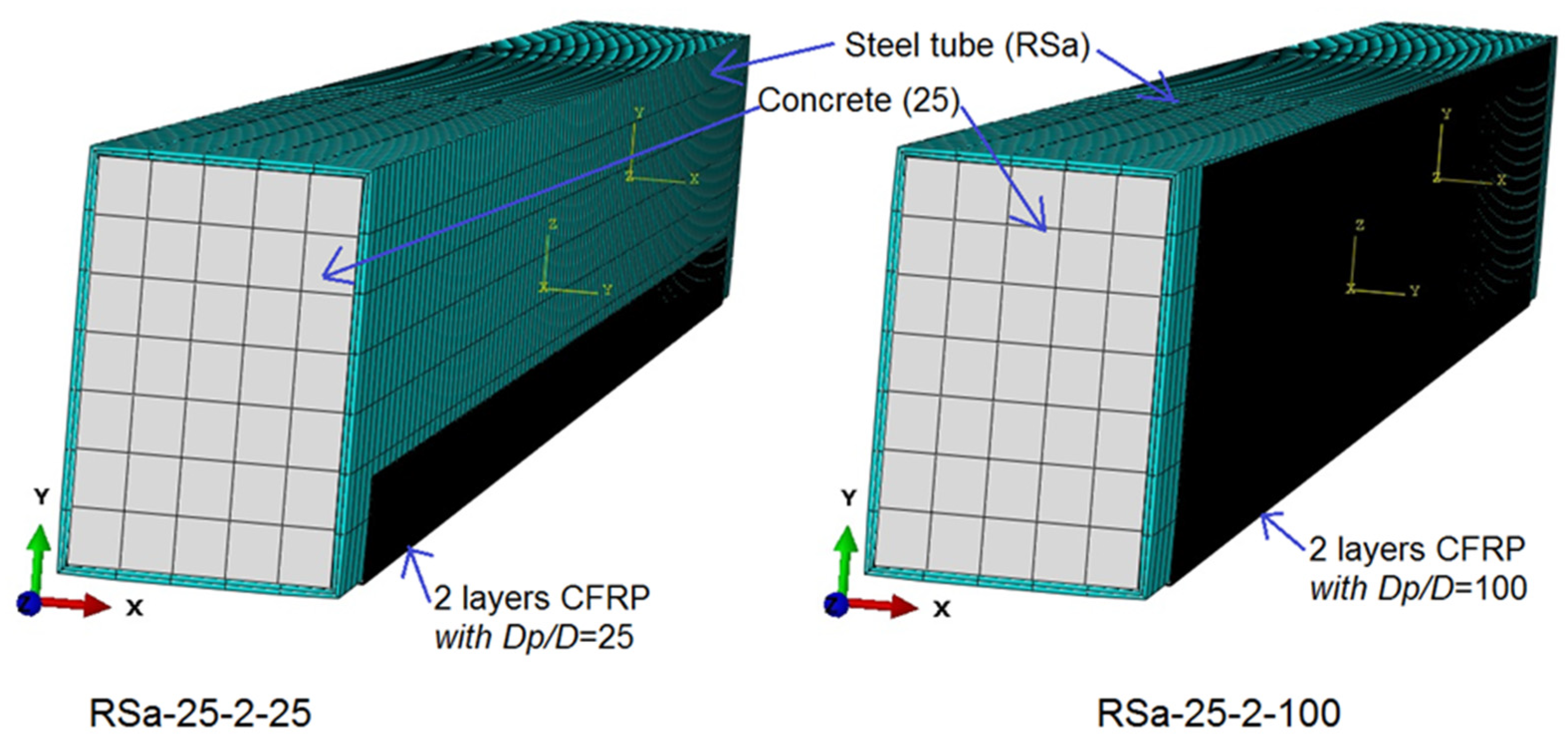
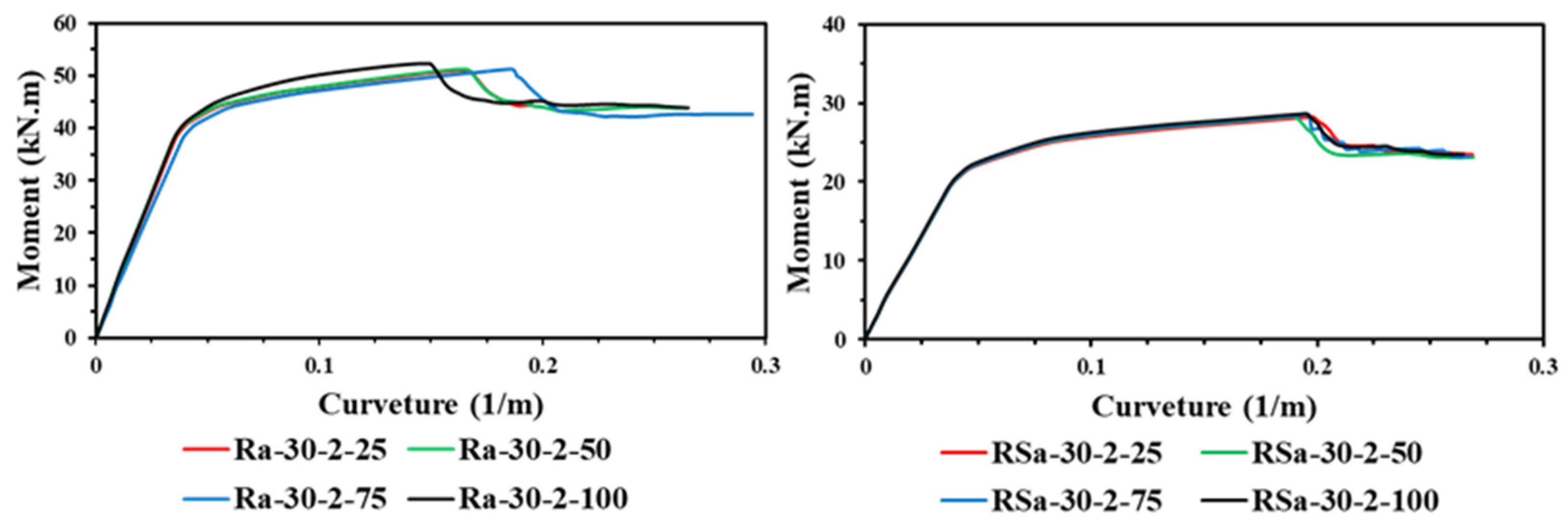
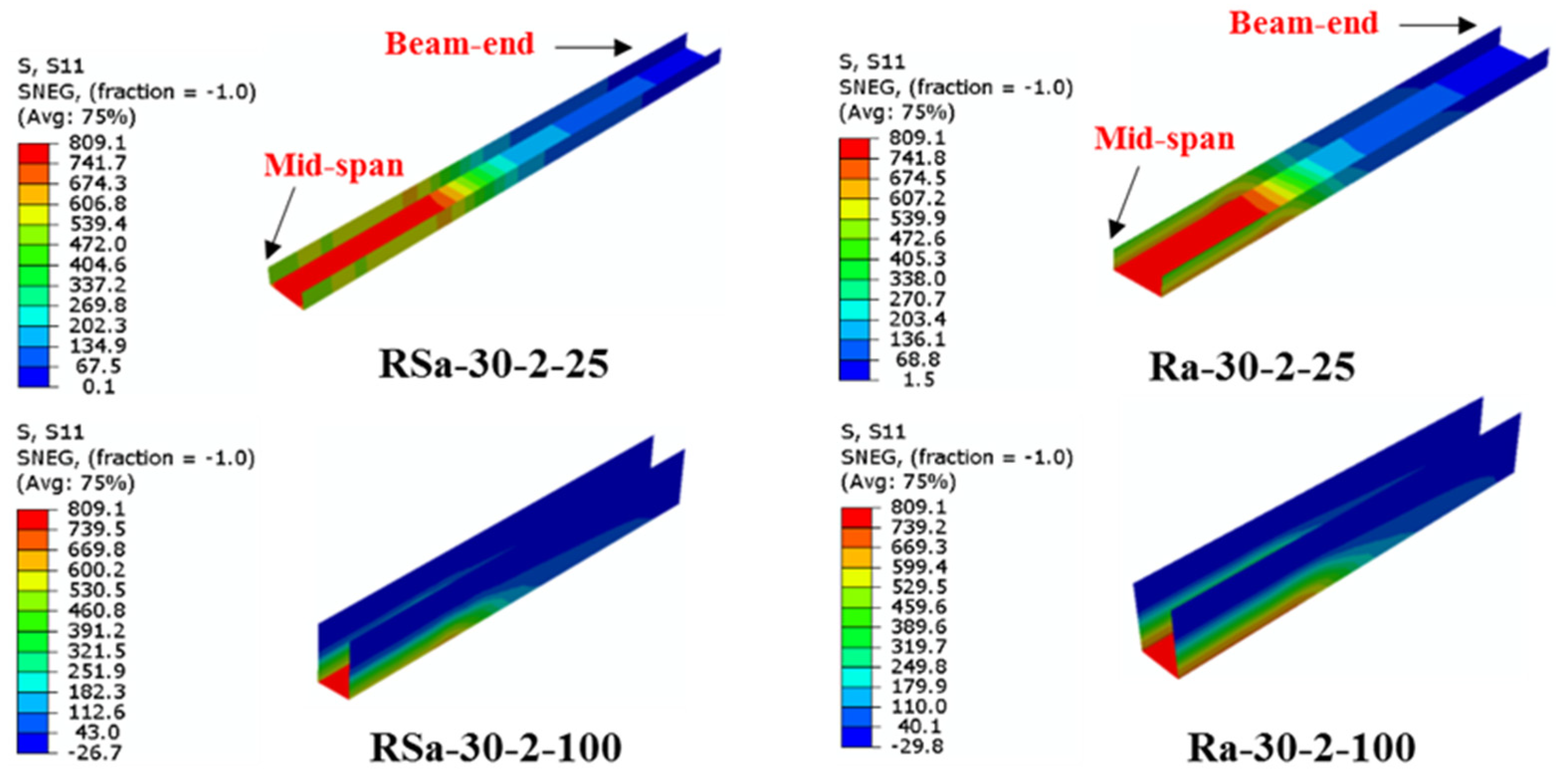
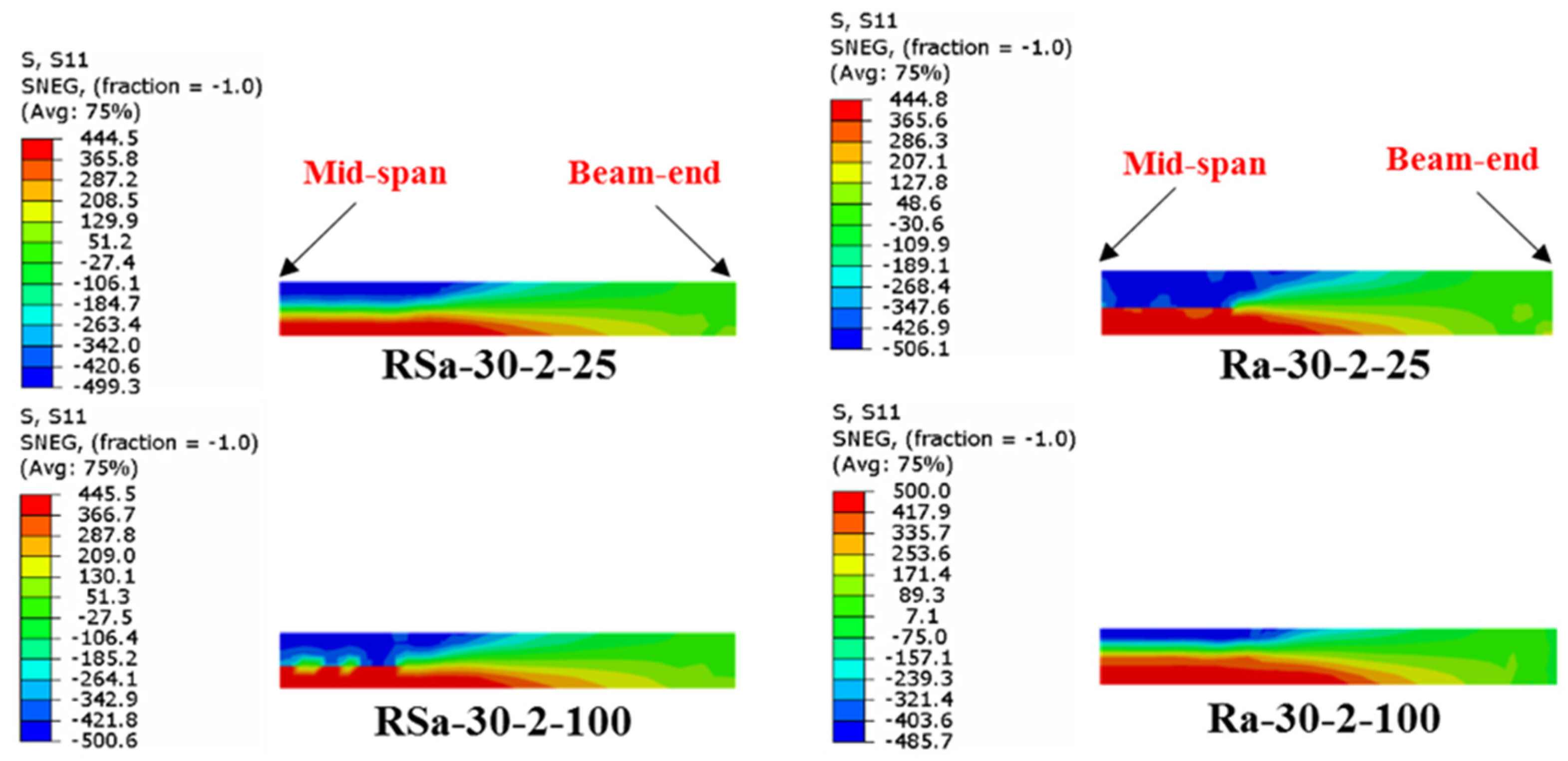
4.3. Effect of Wrapping-Depth Ratio

The effects of varied U-shaped wrapping-depth (η) ratios on the flexural behavior of the U-CFRP-RCFST models are presented in Figure 15. The comparison of the curves reveals no significant differences between the moment–curvature curves of the strengthened RCFST models with different CFRP wrapping-depth ratios. Table 4 indicates the ultimate bending capacities of the analyzed models in this group are marginal increases with increasing the wrapping ratio, where the difference in their MFE values can be neglected. For example, RSa-30-2-100 and Ra-30-2-100 achieve 1.4% and 2.4% higher ultimate bending capacity compared to RSa-30-2-25 and Ra-30-2-25, respectively. This behavior was also observed in previous experimental studies [8] that the ultimate bending capacities of the specimens fully wrapped with CFRP sheets was not much higher than the same specimen when partially wrapped by the same number of CFRP layers (η = 50%). Thus, it can be concluded that increasing η ratio can improve slightly the ultimate bending capacity of U-CFRP-CFST beams. However, its effectiveness subsides for η ratio greater than 50%. This indicated the importance of optimizing the η ratio to obtain efficient and cost-effective structural designs without over-reinforcement.
Figure 16 displays the tensile stress distributed along with the CFRP patches with different wrapping-depth ratios. It is found that increasing the wrapping-depth ratio by more than 50% (wrapping half-depth of model’s cross-section; D/2) did not enhance the ultimate bending capacity of the strengthened RCFST model much, since the top part of the model’s cross-section (above neutral axis) locate in the compression stresses zone where the compressive force of the CFRP patch is significantly small. Similar behavior was recorded for the stresses distributed along the steel tube component of the U-CFRP-RCFST models with varied wrapping-depth ratios (25% to 100%), as presented and compared in Figure 17.
Furthermore, at the ultimate bending capacity of the U-CFRP-RCFST models, the stresses distributed on the concrete cross-section due to the effects of varied η ratios are compared in Figure 18. This figure shows that the area of the compression zone (above the neutral axis) was slightly increased with increases in η ratio gradually from 25% to 100%. Also, it can be seen that the compression area of the concrete core was not much increased when the η ratios pass the 50% (for those with 75 and 100%).

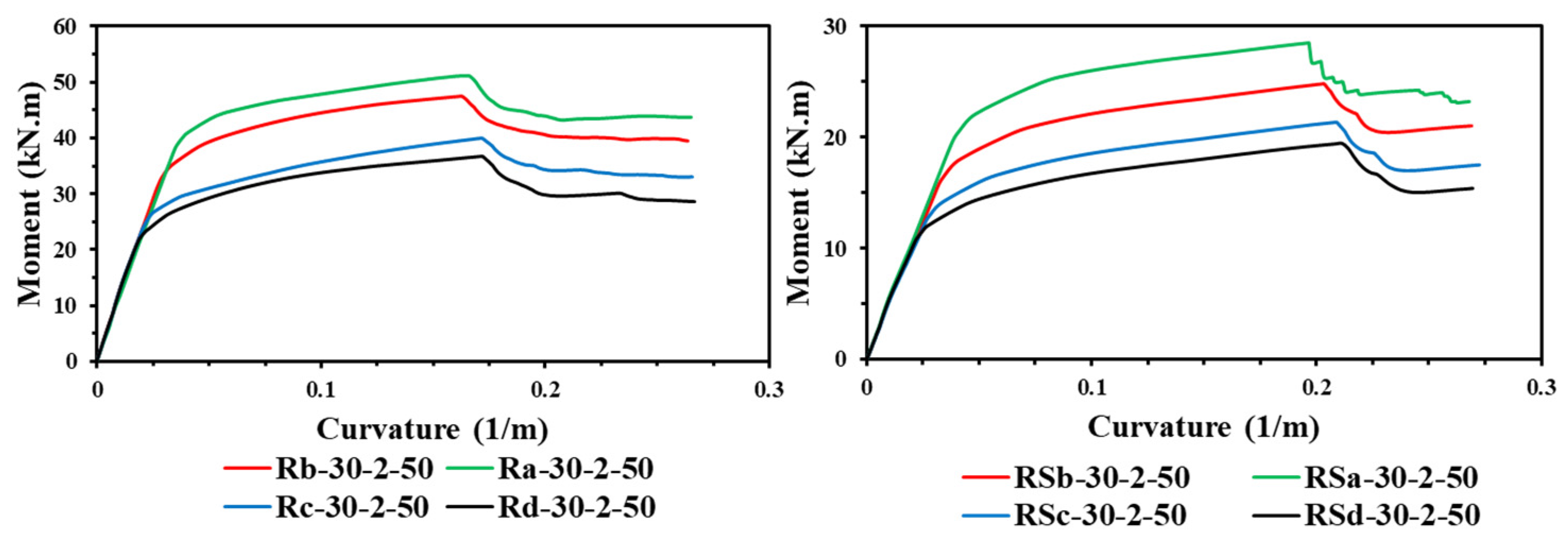
4.4. Effect of Steel Yield Strength

The U-CFRP-RCFST models showed a great impact on their moment–curvature relationships when the steel yield strength has been increased, as shown in Figure 19. As an example, the MFE value of the model Rd-30-2-50 with enhanced of about 39.1% when only the fy increased from 235 MPa to 444 MPa (Ra-30-2-50). The same behavior was recorded for FE models with a smaller rectangular section “RS”, as can be compared in Table 4, the MFE value increased 54.6% as fy increased from 235 MPa to 445.6 MPa.
The changes in the longitudinal stresses of the U-shaped CFRP patch of strengthened RCFST models with varied steel yield strengths are presented and compared in Figure 20, as an example. The FE analysis revealed that the tensile stresses on the tips of the CFRP patch’s web were increased with the reduction in steel yield strength due to the movement in the location of the neutral axis. However, shifting the location of the neutral axis did not prevent the fracture of the CFRP patch from occurring due to the high tensile strain at the bottom flange of the strengthened RCFST model (see Figure 20). Figure 21 demonstrates the influence of varied fy values on the longitudinal stresses distributed along the steel tube of U-CFRP-RCFST models. It can be seen that the models with a smaller section “RS” reached their plastic moment capacities at the mid-span as the steel yield strength reduced from 445.6 MPa to 235 MPa. In the case of models with the larger section “R,” the middle regions of the webs did not reach the yielding stress. Furthermore, Figure 22 illustrates the effect of varied steel yield strengths on the stress distribution on the concrete core cross-section, particularly at the mid-span of the models. The analysis revealed that the compression stress area (above the neutral axis) was increased with a decrease in the steel tube’s yield strength since the neutral axis was moved downward in return to increase the compression strain at the top of the concrete core fiber.

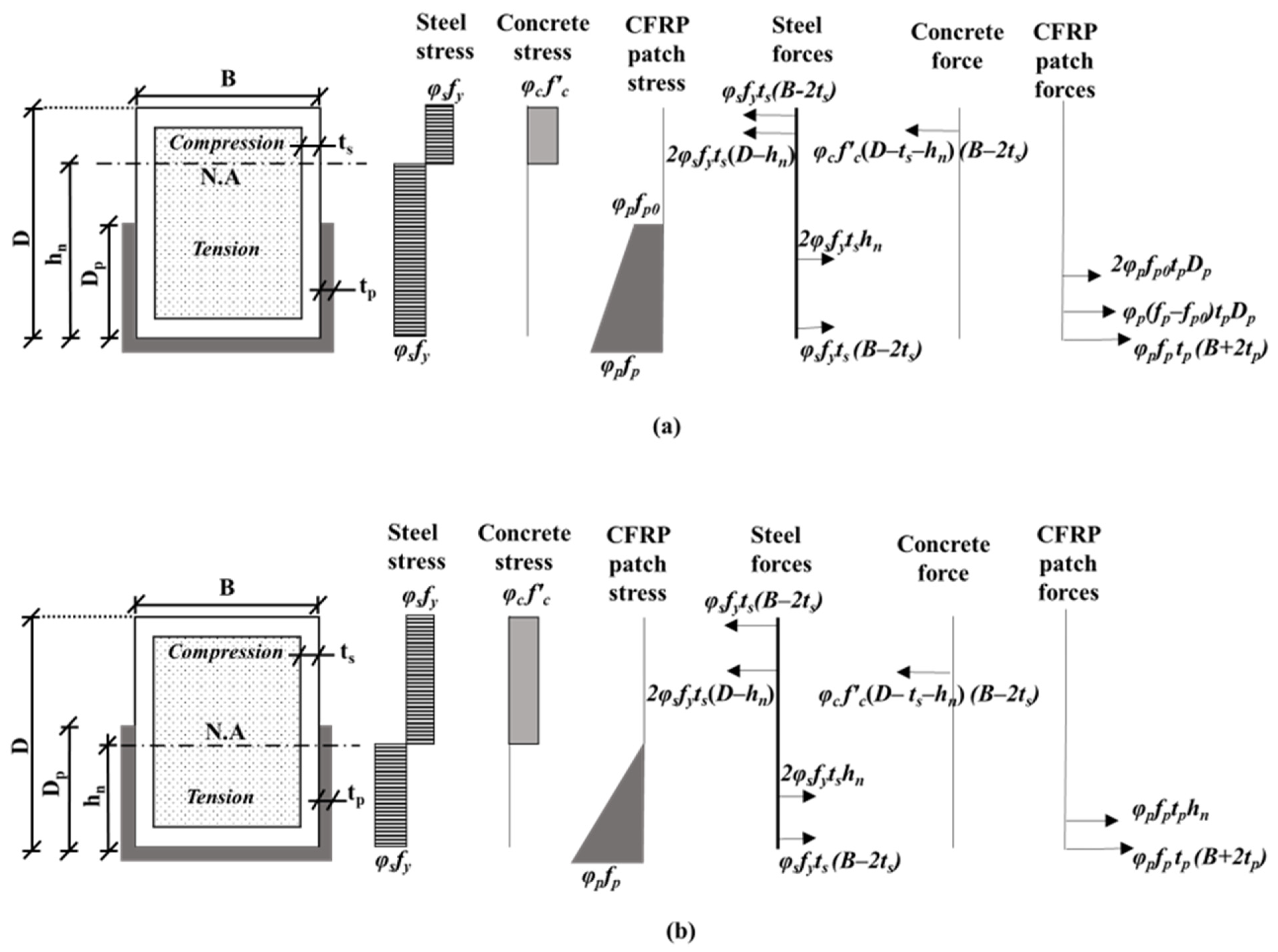
5. Theoretical Modeling

5.1. Development of Stress Block Model
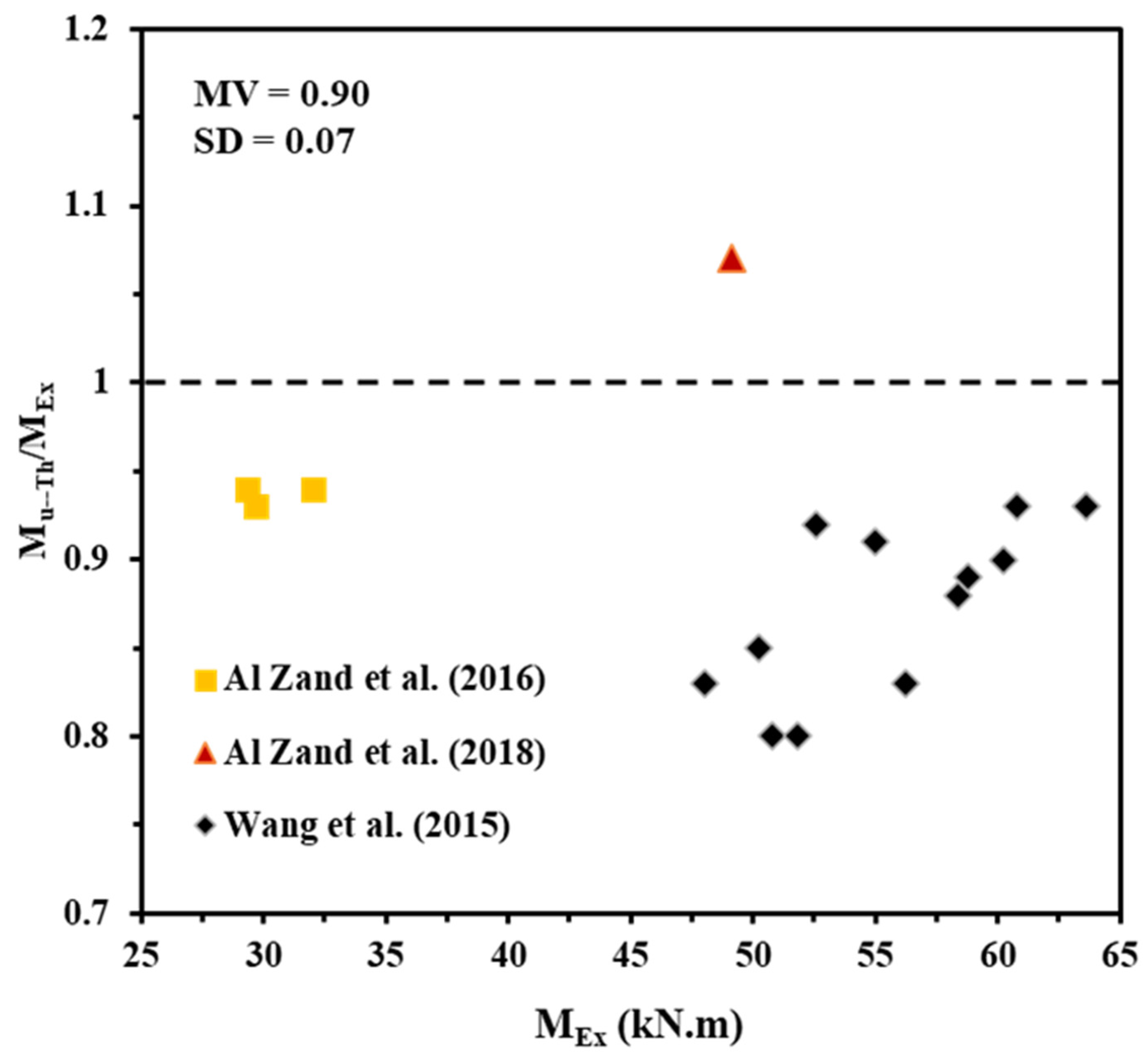
In this section, a new model has been developed for theoretically predicting the ultimate bending capacity of the U-CFRP-RCFST beams. This model is limited to the rectangular CFST beams with steel tubes classified as a compact (Class 1) section. The tension and compression stress distribution on the steel tube, concrete, and CFRP patch cross-section were simplified by stress block models to establish the theoretical model. For the proposed theoretical model, similar to the FE modeling, a single equivalent patch layer was used to represent the multiple CFRP layers and the adhesive layers in between. To simplify the theoretical model, the tensile strength of the concrete and the compressive strength of the CFRP patch were both neglected, as shown in Figure 23.
To model the stress distribution in the steel tube and concrete, the plastic theory was adopted, consistent with the stress block model for CFST beams recommended by Eurocode 4 [12]. This approach was chosen because the steel tube is a compact (Class 1) section, which allows it to develop its full plastic capacity without local buckling. The plastic theory simplifies the analysis by assuming a uniform stress distribution in the steel tube and concrete, enabling an accurate representation of their behavior under ultimate loading conditions. In addition, the current FE analysis confirmed that the steel tubes of the studied models almost achieved their plastic moment capacities. Therefore, referring to Figure 23, the uniform stress blocks equal to φsfy and φcf’c are considered for the steel and concrete infill, respectively.
However, the behavior of the CFRP material is linear elastic until reaching the fracture limit. Therefore, the stress block of the CFRP patch was derived based on the linear strain distribution, which is equal to zero at the neutral axis and increased linearly until reaching its fracture strength at the bottom flange. Figure 23 shows the typical stress block model for the U-CFRP-RCFST beam’s cross-section for two probable locations of the neutral axis. The force of each component (steel tube at tension and compression zones, concrete core at compression zone, and CFRP patch at tension zone) can be determined from their stress limit and the related corresponding area. Furthermore, the location of the neutral axis is determined based on the equilibrium of the internal tensile and compressive forces, as given in the following Equations:
N C = φ s f y t s B 2 t s + 2 φ s f y t s D h n + φ c f c B 2 t s D h n t s
N T = φ s f y t s B 2 t s + 2 φ s f y t s h n + φ p f p t p B + 2 t p + φ p ( f p + f p 0 ) D p t p : h n > D p φ s f y t s B 2 t s + 2 φ s f y t s h n + φ p f p t p B + 2 t p + φ p f p h n t p : h n D p
f p 0 =   f p 1 D p / h n
φs was considered to be 0.95, as suggested by Bong Kwon [14], and φc was taken as 0.85 [11] (φc = 0.67 in case of using fcu instead of f′c). φp was taken as 0.9.
Note that the neutral axis location always passes through the side webs of the CFRP patch when it is applied along the full depth of the steel tube.
Accordingly, referring to the components forces that are estimated from their stress block model, the ultimate bending capacity of U-CFRP-RCFST beams can be derived by taking the moment of these forces about the bending axis (strong axis) of the steel section. The final form of Mu−Th is given in Equation (19).
M u T h = φ s f y Z s Z s n + 0.5 φ c f c Z c Z c n + 0.5 φ p f p t p B + 2 t p D + t p +   φ p f p 0 D p t p ( D D p ) + φ p ( f p f p 0 ) D p t p ( D / 2 D p / 3 ) : h n > D p φ s f y . Z s Z s n + 0.5 φ c f c Z c Z c n + 0.5 φ p f p t p B + 2 t p D + t p + φ p f p h n t p . ( D / 2 h n / 3 ) : h n D p
Z c =   B 2 t s D 2 t s 2 4
  Z s =   B D 2 4 Z c    
  Z c n =   B 2 t s h n 0.5 D 2
Z s n =   2 t s h n 0.5 D 2

5.2. Validation

The results obtained from the FE models of this study as well as from those previously tested specimens by others were used to verify the validity of the proposed theoretical model for predicting the ultimate bending capacity of the CFRP-strengthened RCFST beams. The experimentally tested specimens included one U-wrapped rectangular specimen [9], one fully wrapped rectangular specimen [8], two U-wrapped rectangular specimens [8], and twelve fully wrapped square specimens [16], which are presented in Table 5. The steel tubes of these specimens were classified as compact sections according to Eurocode 4 [12]. Furthermore, to verify the accuracy and robustness of the proposed theoretical model, the same physical properties of the beam’s components (steel tube, concrete, and CFRP sheets) for both of the numerically analyzed FE models (listed in Table 4) and the experimentally tested specimens (listed in Table 5) have been used.
The predicted values of ultimate bending capacities (Mu−Th) using the developed theoretical model are compared with those obtained from the current FE analysis results in Figure 24 and Table 4. The comparison shows that the MV achieved by the overall ratios of Mu−Th/MFE is equal to 0.99, with the very minimum standard of deviation (SD), which is 0.04 (4.0%). The same performance was recorded from the comparison between the predicted results (Mu−Th) of the proposed theoretical model with corresponding experimental results [8,9,16] that are presented in Figure 25 and Table 5, which achieved MV equal to 0.9 and SD of about 0.07 (7.0%). However, it is found that the predicted ultimate bending capacities of the square specimens are slightly conservative due to ignoring the contribution of the transverse layer of CFRP provided in these specimens [16]. In general, this verification study confirms the validity of the proposed theoretical model for predicting the ultimate bending capacity of U-CFRP-RCFST beams. This model is expected to provide engineers with a reliable tool for estimating the most effective wrapping-depth ratio and number of CFRP layers required for strengthening or repairing RCFST beams in practical applications. By offering a systematic approach, the model can enhance decision-making and optimize the design of CFRP-strengthened RCFST beams in the field.

6. Conclusions

In this study, the flexural performance of RCFST beams strengthened using a U-shaped CFRP-wrapping scheme had been numerically investigated in this research, with the effect of the concrete compressive strength, steel yield strength, CFRP layers, and wrapping-depth ratio. In addition, a theoretical model based on block stress model was developed and verified against the FE results of the current study and the existing experimental results. The conclusions are summarized as follows:
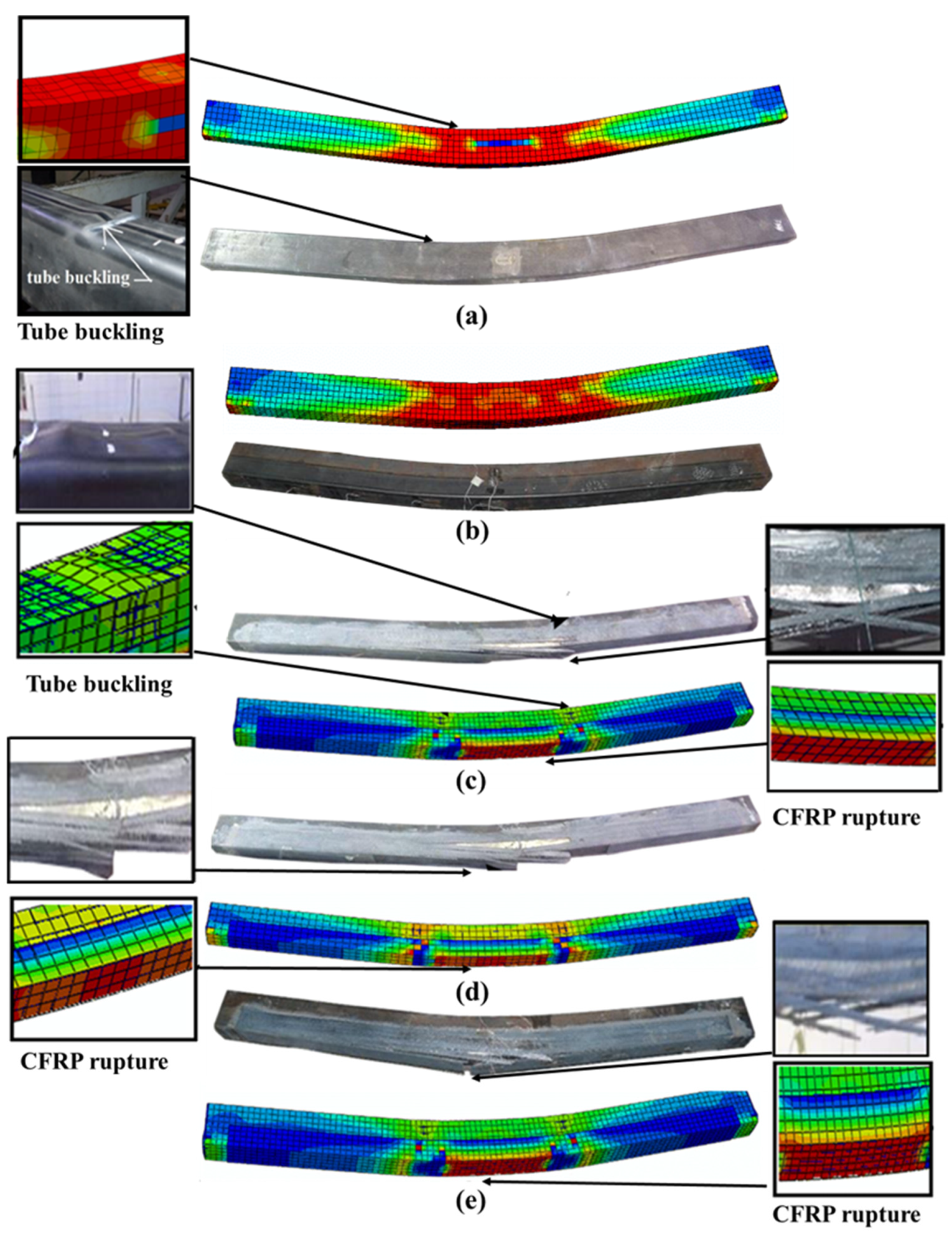
  • The validity of the proposed FE models was confirmed, as they accurately simulated the actual flexural behavior and failure modes of the tested U-CFRP-RCFST beams. The ultimate bending capacities of the developed FE models demonstrated approximately a 5% deviation from those of the corresponding tested specimens.
  • Both the steel yield strength and number of CFRP layers have a major impact on the ultimate bending capacity of the U-shaped CFRP-strengthened RCFST beams, much higher than the effects of other parameters (concrete compressive strength and wrapping-depth ratio).
  • The influence of varied concrete compressive strengths had a minor impact on the ultimate bending capacity of the RCFST beams when strengthened with multi-CFRP layers. This is due to all the steel tubes being with the compact section classification, which can achieve high confinement to the concrete core, as previously proven in previous experimental studies and also proven numerically in the current study.
  • Unlike the influence of using multi-CFRP layers, increasing the depth of the U-shaped wrapping scheme (wrapping-depth ratio) showed very limited impact on improving the ultimate bending capacity of the strengthened RCFST beams, since the bottom fiber of the U-shaped CFRP patch located at the bottom flange of CFST beam usually carrying much higher tensile stresses than that located at both sides of the beam.
  • It was concluded that the proposed theoretical model is reasonably conservative, and it can fairly predict the ultimate bending capacity of the U-CFRP-RCFST beams as the predicted ultimate bending capacity of the U-CFRP-RCFST beams, on average, up to 10% lower compared to the numerical results obtained from the current FE models and existing experimental results. This model is expected to provide engineers with a reliable tool for estimating the most effective wrapping-depth ratio and number of CFRP layers required for strengthening or repairing RCFST beams in practical applications.
Furthermore, more experimental investigation is required for the CFST beams strengthened with U-shaped CFRP layers in order to improve the suggested model based on further actual engineering cases that were not investigated in this numerical research.

Author Contributions

Conceptualization, M.A. (Masoud Abedini) and A.W.A.Z.; methodology, M.A. (Masoud Abedini) and A.W.A.Z.; software, M.A. (Masoud Abedini) and E.H.; validation, M.A. (Masoud Abedini) and A.W.A.Z.; formal analysis, M.A. (Masoud Abedini) and A.W.A.Z.; investigation, E.H. and A.J.; resources, M.A. (Masoud Abedini) and E.H.; data curation, M.A. (Masoud Abedini), E.H. and A.J.; writing—original draft preparation, M.A. (Masoud Abedini) and A.W.A.Z.; writing—review and editing, A.J. and M.A. (Mohammad Ansari); visualization, E.H. and M.A. (Mohammad Ansari); supervision, A.J and M.A. (Mohammad Ansari); project administration, A.W.A.Z., A.J. and M.A. (Mohammad Ansari); funding acquisition, A.W.A.Z. and E.H. All authors have read and agreed to the published version of the manuscript.

Funding

This research received no external funding.

Data Availability Statement

Data are presented in the article.

Acknowledgments

The authors highly acknowledge their Institutes and Universities for the support to prepare and complete this research.

Conflicts of Interest

The authors declare no conflict of interest.

Nomenclature

Width of the steel tube (B); depth of the steel tube (D); depth of CFRP patch (Dp); compressive damage parameter (dc); tensile damage parameter (dt); modulus of elasticity of adhesive material (Ea); modulus of elasticity of concrete (Ec); modulus of elasticity of CFRP sheets (ECF); modulus of elasticity of CFRP patch (Ep); modulus of elasticity of steel (Es); tensile strength of adhesive material (fa); characteristic cylinder strength of concrete (f’c); tensile strength of CFRP sheets (fCF); uniaxial tensile strength of concrete (fcr); characteristic cube strength of concrete (fcu); tensile strength of CFRP patch (fp); tensile stress of concrete (ft); steel ultimate tensile strength (fu); steel yield strength (fy); distance between the neutral axis and the bottom flange of the steel tube (hn); ultimate bending capacity from experimental tests (MEx); ultimate bending capacity from FE analysis (MFE); ultimate bending capacity (Mu); theoretically predicted ultimate bending capacity (Mu−Th); internal compressive force of the composite beam section (Nc); internal tensile force of the composite beam section (Nt); number of CFRP layers (n); thickness of adhesive layer (ta); thickness of CFRP sheet (tCF); thickness of CFRP patch (tp); thickness of steel tube (ts); plastic section modulus of concrete core (Zc); plastic section modulus of steel tube (Zs); concrete compressive strain (εc); engineering strain (from tensile test) (εeng); compressive plastic strain of concrete (εpc); tensile plastic strain of concrete (εpt); concrete tensile strain (εt); true strain (εtrue); wrapping-depth ratio (Dp/D) (η); engineering stress (from tensile test) (σeng); true stress (σtrue); material factor for concrete (φc); material factor for CFRP patch (φp); material factor for steel (φs).

References

  1. Tang, H.; Wang, H.; Liu, Y.; Sun, X.; Huang, X. Behaviour of CFRP Confined Square Concrete-Filled Stainless Steel Tubular Columns under Uni-Axial Compression. Thin-Walled Struct. 2023, 183, 110440. [Google Scholar] [CrossRef]
  2. Miao, K.; Wei, Y.; Zhang, S.; Zheng, K.; Ding, M. Eccentric Compression Behavior of Concrete-Filled Steel Tube Columns Strengthened by CFRP/Steel Strip. Eng. Struct. 2023, 287, 116191. [Google Scholar] [CrossRef]
  3. Tao, Z.; Han, L.-H. Behaviour of Fire-Exposed Concrete-Filled Steel Tubular Beam Columns Repaired with CFRP Wraps. Thin-Walled Struct. 2007, 45, 63–76. [Google Scholar] [CrossRef]
  4. Wang, Q.L.; Shao, Y.B. Flexural Performance of Circular Concrete Filled Cfrp-Steel Tubes. Adv. Steel Constr. 2015, 11, 127–149. [Google Scholar] [CrossRef]
  5. Al-Zand, A.W.; Badaruzzaman, W.H.W.; Mutalib, A.A.; Hilo, S.J. Rehabilitation and Strengthening of High-Strength Rectangular CFST Beams Using a Partial Wrapping Scheme of CFRP Sheets: Experimental and Numerical Study. Thin-Walled Struct. 2017, 114, 80–91. [Google Scholar] [CrossRef]
  6. Sundarraja, M.C.; Ganesh Prabhu, G. Finite Element Modelling of CFRP Jacketed CFST Members under Flexural Loading. Thin-Walled Struct. 2011, 49, 1483–1491. [Google Scholar] [CrossRef]
  7. Sundarraja, M.C.; Prabhu, G.G. Experimental Investigation on Strengthening of CFST Members Under Flexure Using CFRP Fabric. Arab. J. Sci. Eng. 2014, 39, 659–668. [Google Scholar] [CrossRef]
  8. Al-Zand, A.W.; Badaruzzaman, W.H.W.; Mutalib, A.A.; Hilo, S.J. The Enhanced Performance of CFST Beams Using Different Strengthening Schemes Involving Unidirectional CFRP Sheets: An Experimental Study. Eng. Struct. 2016, 128, 184–198. [Google Scholar] [CrossRef]
  9. Al-Zand, A.W.; Badaruzzaman, W.H.W.; Mutalib, A.A.; Hilo, S.J. Flexural Behavior of CFST Beams Partially Strengthened with Unidirectional CFRP Sheets: Experimental and Theoretical Study. J. Compos. Constr. 2018, 22, 4018018. [Google Scholar] [CrossRef]
  10. Du, Y.; Gao, D.; Chen, Z.; Deng, X.; Qian, K. Experimental Study on the Flexural Behavior of Square High-Strength Concrete-Filled Steel Tube Beams with Different CFRP Wrapping Schemes. Compos. Struct. 2023, 304, 116325. [Google Scholar] [CrossRef]
  11. AISC ANSI/AISC 360-10; Specification for Structural Steel Buildings. American Institute of Steel Construction: Chicago, IL, USA, 2010.
  12. Eurocode 4 EN 1994; Design of Composite Steel and Concrete Structures. Comité Europeo de Normalización: Brussels, Belgium, 1992.
  13. AIJ; Recommendations for Design and Construction of Concrete Filled Steel Tubular Structures. Architectural Institute of Japan: Tokyo, Japan, 1997.
  14. Bong Kwon, Y.; Kyu Jeong, I.; Kwon, Y.B.; Jeong, I.K. Resistance of Rectangular Concrete-Filled Tubular (CFT) Sections to the Axial Load and Combined Axial Compression and Bending. Thin-Walled Struct. 2014, 79, 178–186. [Google Scholar] [CrossRef]
  15. Lai, Z.; Varma, A.H.; Zhang, K. Noncompact and Slender Rectangular CFT Members: Experimental Database, Analysis, and Design. J. Constr. Steel Res. 2014, 101, 455–468. [Google Scholar] [CrossRef]
  16. Wang, Q.L.; Li, J.; Shao, Y.B.; Zhao, W.J. Flexural Performances of Square Concrete Filled CFRP-Steel Tubes (S-CF-CFRP-ST). Adv. Struct. Eng. 2015, 18, 1319–1344. [Google Scholar] [CrossRef]
  17. He, X.; Ke, K.; Zhou, X. Closed-Form Design Solutions for Parallelogram Hollow Structural Sections under Bending Scenarios. J. Constr. Steel Res. 2023, 207, 107934. [Google Scholar] [CrossRef]
  18. Tahenni, T.; Bouziadi, F.; Boulekbache, B.; Amziane, S. Experimental and Nonlinear Finite Element Analysis of Shear Behaviour of Reinforced Concrete Beams. Structures 2021, 29, 1582–1596. [Google Scholar] [CrossRef]
  19. Uslu, F.; Taşkın, K. Experimental and Finite Element Method Investigation of Axial Load Carrying Capacity of Concrete Filled Circular Steel Tube Columns According to Different Slenderness Ratios. Int. J. Steel Struct. 2024, 24, 619–634. [Google Scholar] [CrossRef]
  20. Wang, J.; Cheng, L.; Yang, J. Compressive Behavior of CFRP-Steel Composite Tubed Steel-Reinforced Columns with High-Strength Concrete. J. Constr. Steel Res. 2018, 150, 354–370. [Google Scholar] [CrossRef]
  21. Ansari, M.; Jeddi, M.Z.; Badaruzzaman, W.H.W.; Tahir, M.M.; Osman, S.A.; Hosseinpour, E. A Numerical Investigation on the through Rib Stiffener Beam to Concrete-Filled Steel Tube Column Connections Subjected to Cyclic Loading. Eng. Sci. Technol. Int. J. 2021, 24, 728–735. [Google Scholar] [CrossRef]
  22. Choi, I.R.; Chung, K.S.; Kim, C.S. Experimental Study on Rectangular CFT Columns with Different Steel Grades and Thicknesses. J. Constr. Steel Res. 2017, 130, 109–119. [Google Scholar] [CrossRef]
  23. Eurocode 2 EN 1992-1-1; Design of Concrete Structures-Part 1-1: General Ruels and Rules for Buildings. Comité Europeo de Normalización: Brussels, Belgium, 2004.
  24. Wang, T.; Hsu, T.T.C. Nonlinear Finite Element Analysis of Concrete Structures Using New Constitutive Models. Comput. Struct. 2001, 79, 2781–2791. [Google Scholar] [CrossRef]
  25. Systèmes, D. Abaqus 6.10: Analysis User’s Manual. Provid; RI Dassault Systèmes Simulia Corp.: Vélizy-Villacoublay, France, 2010. [Google Scholar]
  26. Fawzia, S.; Al-Mahaidi, R.; Zhao, X.-L. Experimental and Finite Element Analysis of a Double Strap Joint between Steel Plates and Normal Modulus CFRP. Compos. Struct. 2006, 75, 156–162. [Google Scholar] [CrossRef]
  27. Al-Zubaidy, H.; Al-Mahaidi, R.; Zhao, X.-L. Finite Element Modelling of CFRP/Steel Double Strap Joints Subjected to Dynamic Tensile Loadings. Compos. Struct. 2013, 99, 48–61. [Google Scholar] [CrossRef]
  28. Bsisu, K.A.-D.; Hussein, H.H.; Sargand, S.M. The Use of Hashin Damage Criteria, CFRP–Concrete Interface and Concrete Damage Plasticity Models in 3D Finite Element Modeling of Retrofitted Reinforced Concrete Beams with CFRP Sheets. Arab. J. Sci. Eng. 2017, 42, 1171–1184. [Google Scholar] [CrossRef]
  29. Moldovan, I.-F.; Nedelcu, M.; Buru, S.-M. Analysing the Performance of Hollow Core Slabs Strengthened with CFRP. In IOP Conference Series: Materials Science and Engineering; IOP Publishing: Prague, Czech Republic, 2021; Volume 1203, p. 32056. [Google Scholar]
Figure 1. Schematic loading scenario of the studied FE models (unit: mm).
Infrastructures 10 00073 g001
Figure 2. Boundary conditions of the 3D FE model.
Infrastructures 10 00073 g002
Figure 3. Typical stress–strain relationship of concrete.
Infrastructures 10 00073 g003
Figure 4. Moment–curvature relationships of FE models and related experimental specimens.
Infrastructures 10 00073 g004
Figure 5. Comparison between the failure mode of the FE models and the experimental specimens. (a) RS (b) R (c) RS-100P-2L (d) RS-100P-3L (e) R-P100-2L.
Infrastructures 10 00073 g005
Figure 6. Typical rectangular CFST models with varied CFRP-wrapping-depth.
Infrastructures 10 00073 g006
Figure 7. Moment–curvature relationships of FE models with varied CFRP layers.
Infrastructures 10 00073 g007
Figure 8. The effect of CFRP layers on the longitudinal stress (CFRP patch).
Infrastructures 10 00073 g008
Figure 9. The effect of CFRP layers on the longitudinal stress (steel tube’s web).
Infrastructures 10 00073 g009
Figure 10. The effect of CFRP layers on the longitudinal stress (concrete cross-section).
Infrastructures 10 00073 g010
Figure 11. Moment–curvature relationships of FE models with varied concrete strength.
Infrastructures 10 00073 g011
Figure 12. The effect of concrete strength on the longitudinal stress (CFRP patch).
Infrastructures 10 00073 g012
Figure 13. The effect of concrete strength on the longitudinal stress (steel tube’s web).
Infrastructures 10 00073 g013
Figure 14. The effect of concrete strength on longitudinal stress (concrete cross-section).
Infrastructures 10 00073 g014
Figure 15. Moment–curvature relationships of FE models with varied wrapping-depth ratios.
Infrastructures 10 00073 g015
Figure 16. The effect of wrapping-depth ratio on the longitudinal stress (CFRP patch).
Infrastructures 10 00073 g016
Figure 17. The effect of wrapping-depth ratio on longitudinal stress (steel tube’s web).
Infrastructures 10 00073 g017
Figure 18. The effect of wrapping-depth ratio on the longitudinal stress (concrete cross-section).
Infrastructures 10 00073 g018
Figure 19. Moment–curvature relationships of FE models with varied steel-yielding strengths.
Infrastructures 10 00073 g019
Figure 20. The effect of steel yield strength on the longitudinal stress (CFRP patch).
Infrastructures 10 00073 g020
Figure 21. The effect of steel yield strength on the longitudinal stress (steel tube’s web).
Infrastructures 10 00073 g021
Figure 22. The effect of steel yield strength on the longitudinal stress (concrete cross-section).
Infrastructures 10 00073 g022
Figure 23. Stress block model of the U-CFRP-CFST beams. (a) Neutral axis locates above CFRP patch’s webs (b) Neutral axis passes through CFRP patch’s webs.
Infrastructures 10 00073 g023
Figure 24. Verification of theoretical model with FE results.
Infrastructures 10 00073 g024
Figure 25. Verification of theoretical model with experimental results [8,9,16].
Infrastructures 10 00073 g025
Table 1. Specifications of the FE models.
Specimen’s LabelD × B × ts
(mm)
fcu
(MPa)
CFRP Layersη
(%)
MEX
(kN.m)
MFE
(kN.m)
MFE/MExRef.
RS125 × 75 × 2.831.50022.722.490.99[8]
RS-100P-2L125 × 75 × 2.831.525029.328.560.97
RS-100P-3L125 × 75 × 2.831.535032.030.400.95
R150 × 100 × 3.731.50040.642.371.04[9]
R-100P-2L150 × 100 × 3.731.525049.151.171.04
MV1.00
SD0.04
Table 2. Mechanical properties of steel.
D × B × ts
(mm)
Modulus of Elasticity
Es (GPa)
Yield Strength
fy (MPa)
Ultimate Tensile Strength
fu (MPa)
Elongation
(%)
Ref.
125 × 75 × 2.8205.6445.6482.315.4[8]
150 × 100 × 3.7194.0444.0531.019.9[9]
Table 3. Concrete damage plasticity parameters.
Dilation AngleEccentricityfb0/fc0KViscosity
400.11.160.6670.0001
Table 4. Specifications and ultimate bending capacities of the FE models.
FE Model’s LabelD × B × ts
(mm)
nη
(%)
fcu
(MPa)
fy
(MPa)
MFE
(kN.m)
Mu−Th
(kN.m)
Mu−Th/MFE
RSa-30125 × 75 × 2.80031.5445.622.520.30.90
RSa-30-1-50125 × 75 × 2.815031.5445.625.524.60.96
RSa-30-2-50125 × 75 × 2.825031.5445.628.627.60.97
RSa-30-3-50125 × 75 × 2.835031.5445.630.430.20.99
RSa-30-4-50125 × 75 × 2.845031.5445.632.132.41.01
RSa-25-2-50125 × 75 × 2.825025.0445.628.227.00.96
RSa-35-2-50125 × 75 × 2.825035.0445.628.728.00.98
RSa-40-2-50125 × 75 × 2.825040.0445.628.928.40.98
RSa-30-2-25125 × 75 × 2.822531.5445.628.227.50.98
RSa-30-2-75125 × 75 × 2.827531.5445.628.327.60.98
RSa-30-2-100125 × 75 × 2.8210031.5445.628.627.60.97
RSb-30-2-50125 × 75 × 2.825031.5355.023.724.81.05
RSc-30-2-50125 × 75 × 2.825031.5275.020.221.41.06
RSd-30-2-50125 × 75 × 2.825031.5235.018.519.51.05
Ra-30150 × 100 × 3.70031.5444.042.440.60.96
Ra-30-1-50150 × 100 × 3.715031.5444.049.947.70.96
Ra-30-2-50150 × 100 × 3.725031.5444.051.252.61.03
Ra-30-3-50150 × 100 × 3.735031.5444.056.956.91.00
Ra-30-4-50150 × 100 × 3.745031.5444.059.560.71.02
Ra-25-2-50150 × 100 × 3.725025.0444.050.551.41.02
Ra-35-2-50150 × 100 × 3.725035.0444.051.253.11.04
Ra-40-2-50150 × 100 × 3.725040.0444.051.553.91.05
Ra-30-2-25150 × 100 × 3.722531.5444.051.052.21.02
Ra-30-2-75150 × 100 × 3.727531.5444.051.352.61.03
Ra-30-2-100150 × 100 × 3.7210031.5444.052.252.61.01
Rb-30-2-50150 × 100 × 3.725031.5355.047.544.80.94
Rc-30-2-50150 × 100 × 3.725031.5275.039.937.80.95
Rd-30-2-50150 × 100 × 3.725031.5235.036.834.40.93
MV0.99
SD0.04
Table 5. Properties of the test specimens.
Experimental Specimen’s LabelD × B × ts
(mm)
fy
(MPa)
fcu
(MPa)
nη
(%)
Wrapping SchemeMEx (kN.m)Mu−Th
(kN.m)
Mu−Th/MEx
RS-F100-2L125 × 75 × 2.8445.631.52100Full29.727.640.93
RS-P100-2L125 × 75 × 2.8445.631.5250U-shaped29.327.640.94
RS-P100-3L125 × 75 × 2.8445.631.5350U-shaped3230.220.94
R-P100-2L150 × 100 × 3.744431.5250U-shaped49.152.571.07
SB A-1140 × 140 × 3.5300331100Full4839.850.83
SB A-2140 × 140 × 3.5300332100Full56.246.890.83
SB A-3140 × 140 × 3.5300333100Full58.852.510.89
SB B-1140 × 140 × 3.530039.41100Full50.840.640.80
SB B-2140 × 140 × 3.530039.42100Full52.648.180.92
SB B-3140 × 140 × 3.530039.43100Full60.254.340.90
SB C-1140 × 140 × 3.5300491100Full51.841.640.80
SB C-2140 × 140 × 3.5300492100Full5549.840.91
SB C-3140 × 140 × 3.5300493100Full60.856.710.93
SB D-1140 × 140 × 3.530059.71100Full50.242.560.85
SB D-2140 × 140 × 3.530059.72100Full58.451.370.88
SB D-3140 × 140 × 3.530059.73100Full63.658.930.93
MV0.90
SD0.07
Disclaimer/Publisher’s Note: The statements, opinions and data contained in all publications are solely those of the individual author(s) and contributor(s) and not of MDPI and/or the editor(s). MDPI and/or the editor(s) disclaim responsibility for any injury to people or property resulting from any ideas, methods, instructions or products referred to in the content.

