Development of a Stress Block Model to Predict the Ultimate Bending Capacity of Rectangular Concrete-Filled Steel Tube Beams Strengthened with U-Shaped CFRP Sheets
Abstract
:1. Introduction
2. Finite Element Modeling
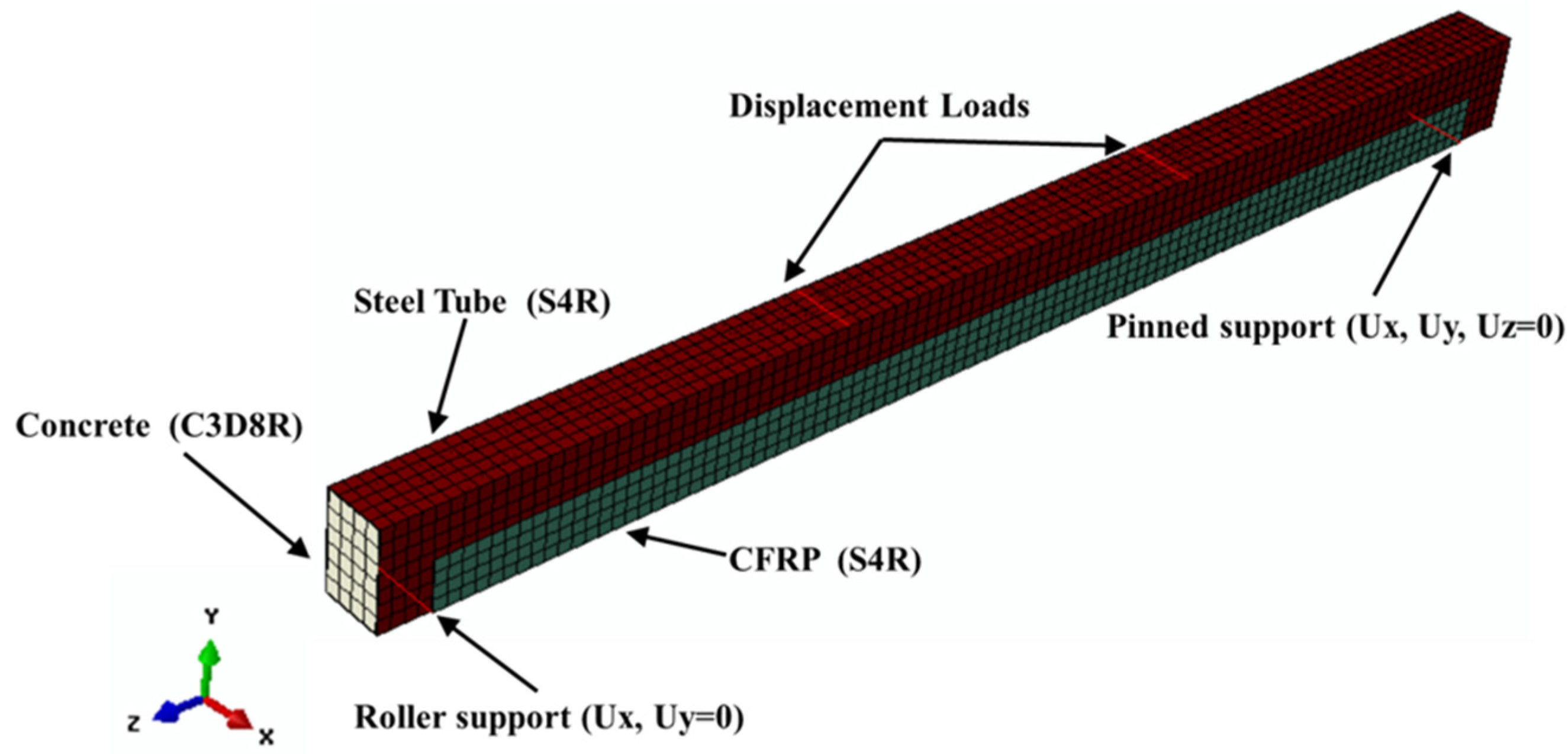
2.1. Boundary Conditions and Element Description
2.2. Surface Interaction
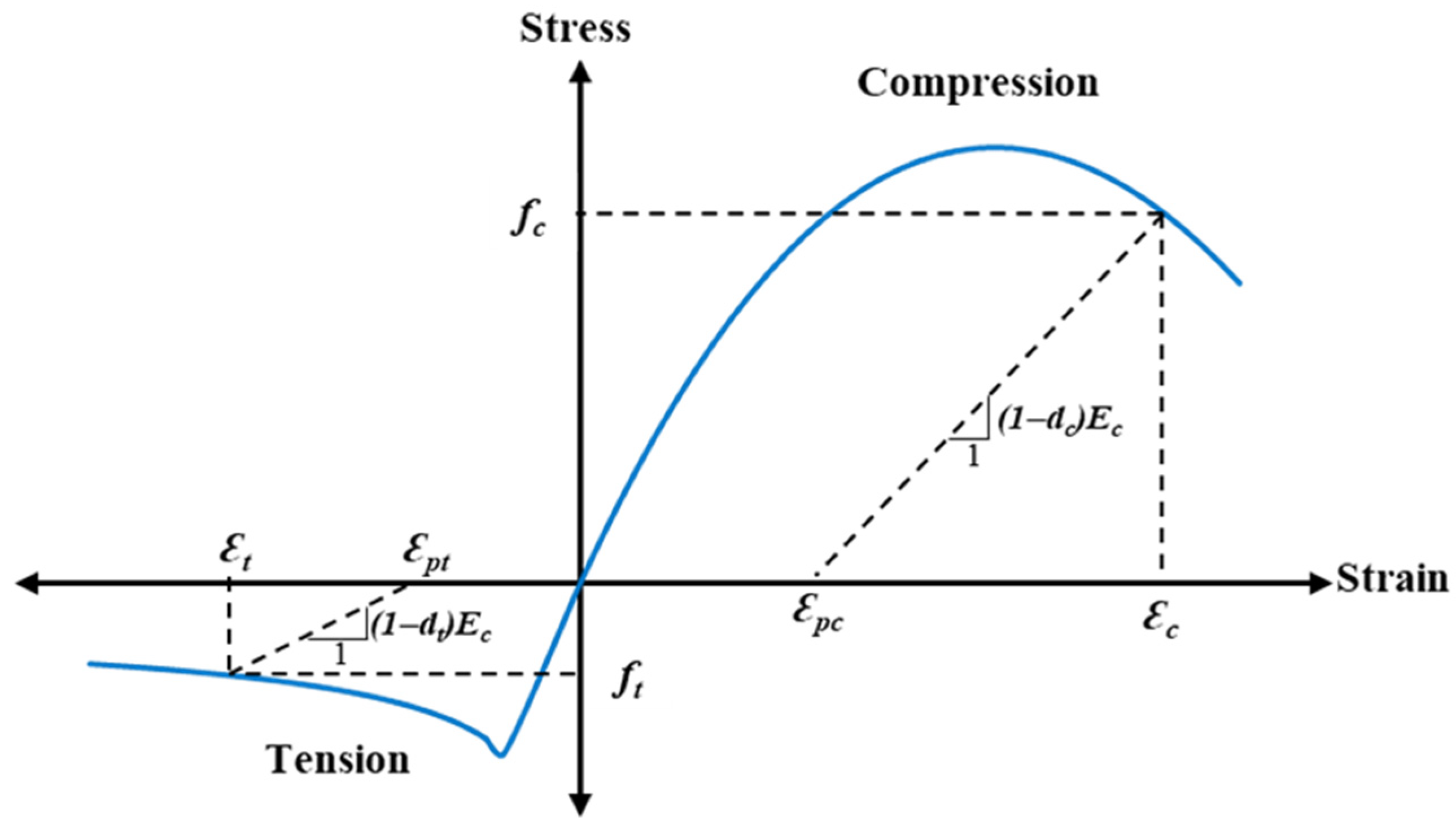
2.3. Material Properties and Modeling
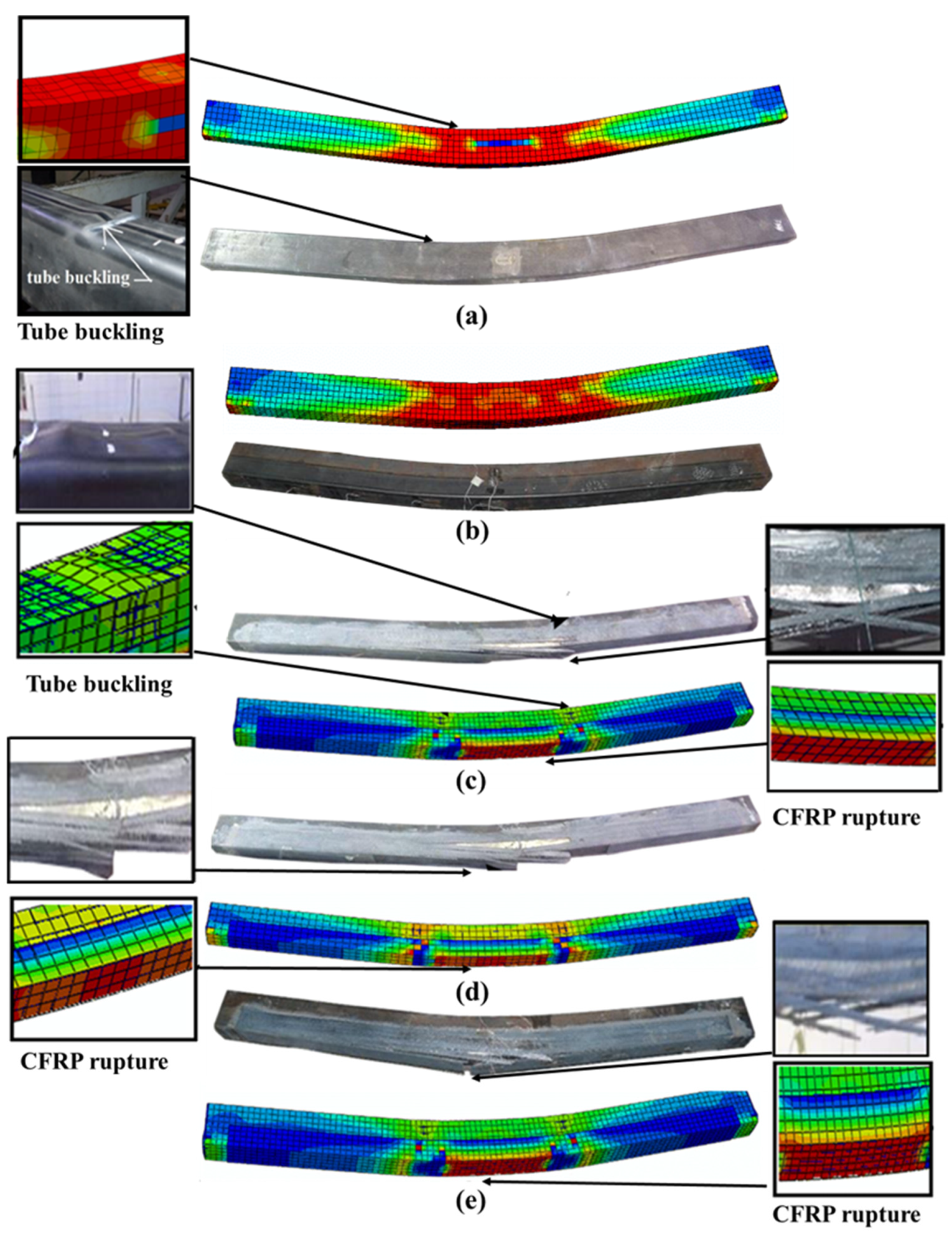
2.4. FE Models Verification
3. Parametric Study
4. Results and Discussion
4.1. Effect of CFRP Layers
4.2. Effect of Concrete Compressive Strength
4.3. Effect of Wrapping-Depth Ratio
4.4. Effect of Steel Yield Strength
5. Theoretical Modeling
5.1. Development of Stress Block Model
5.2. Validation
6. Conclusions
- The validity of the proposed FE models was confirmed, as they accurately simulated the actual flexural behavior and failure modes of the tested U-CFRP-RCFST beams. The ultimate bending capacities of the developed FE models demonstrated approximately a 5% deviation from those of the corresponding tested specimens.
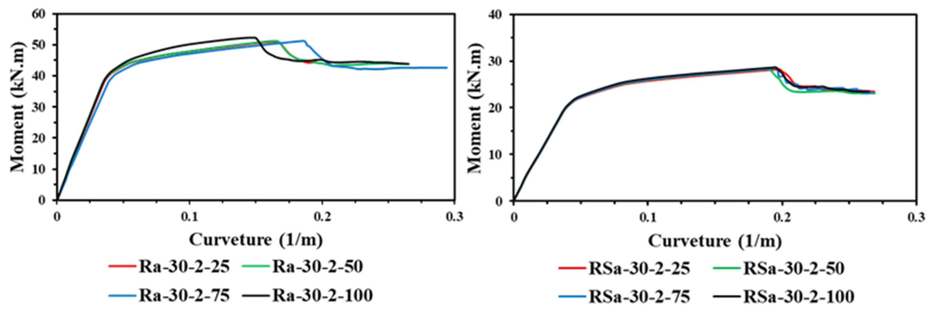
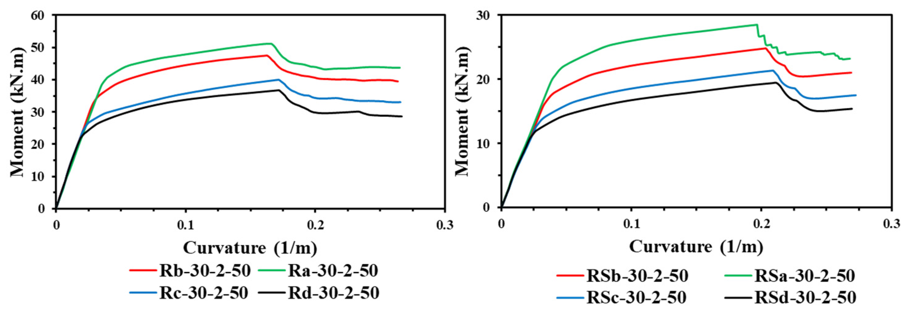
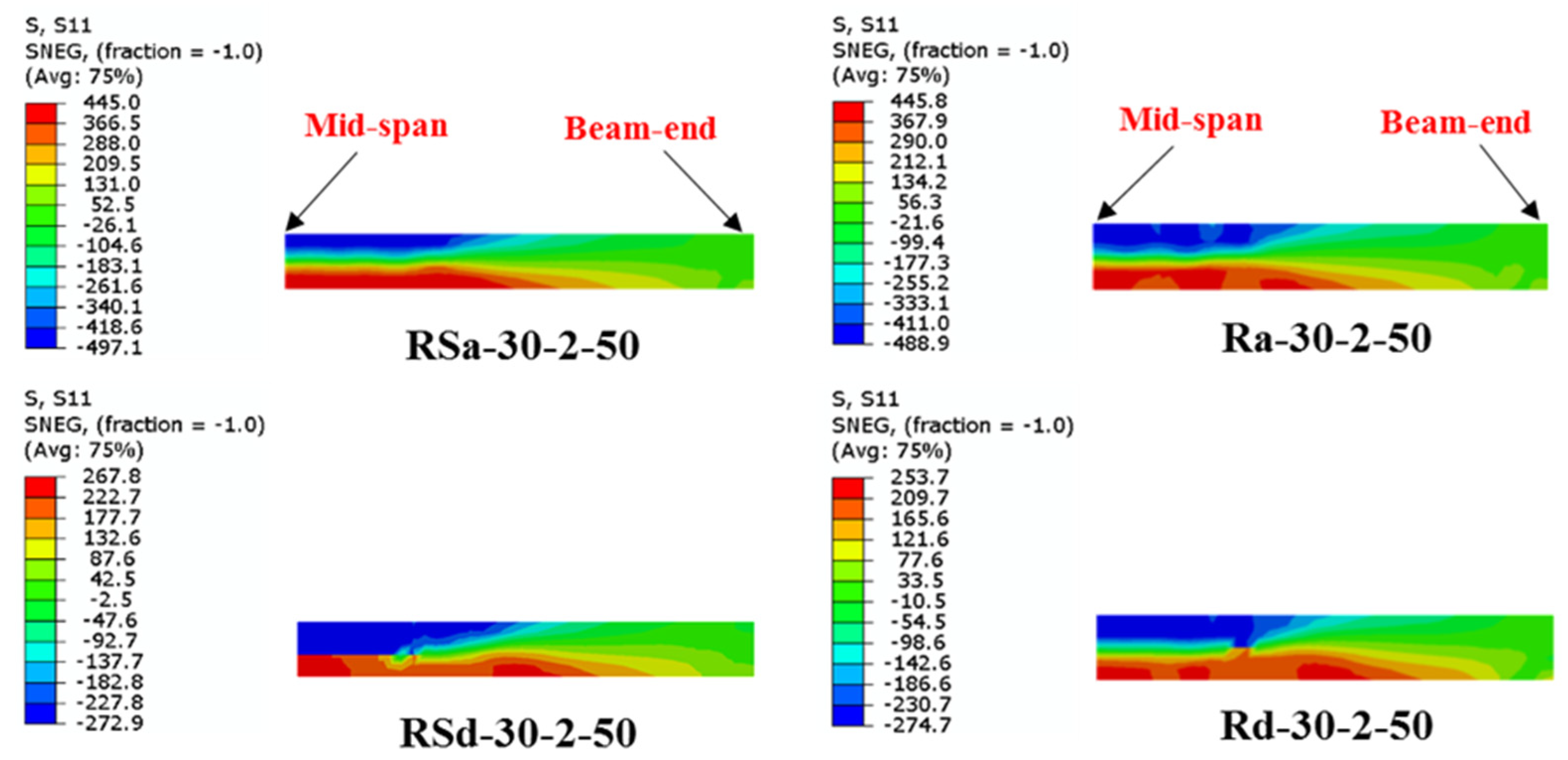
- Both the steel yield strength and number of CFRP layers have a major impact on the ultimate bending capacity of the U-shaped CFRP-strengthened RCFST beams, much higher than the effects of other parameters (concrete compressive strength and wrapping-depth ratio).
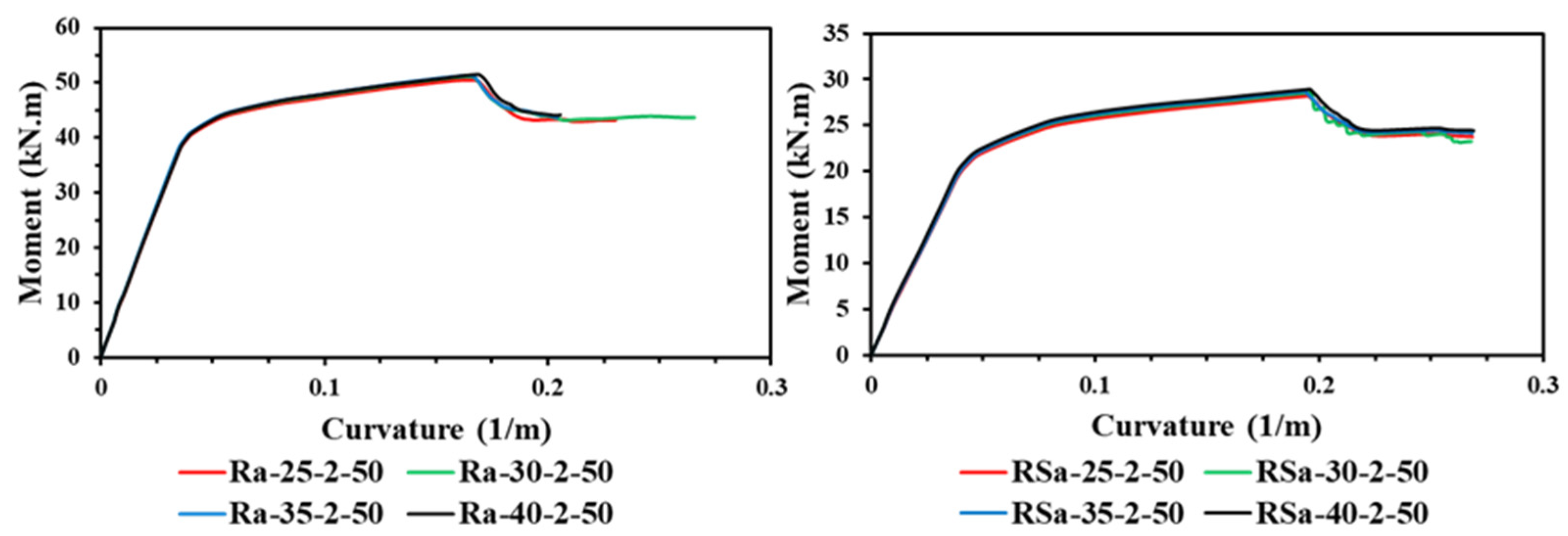
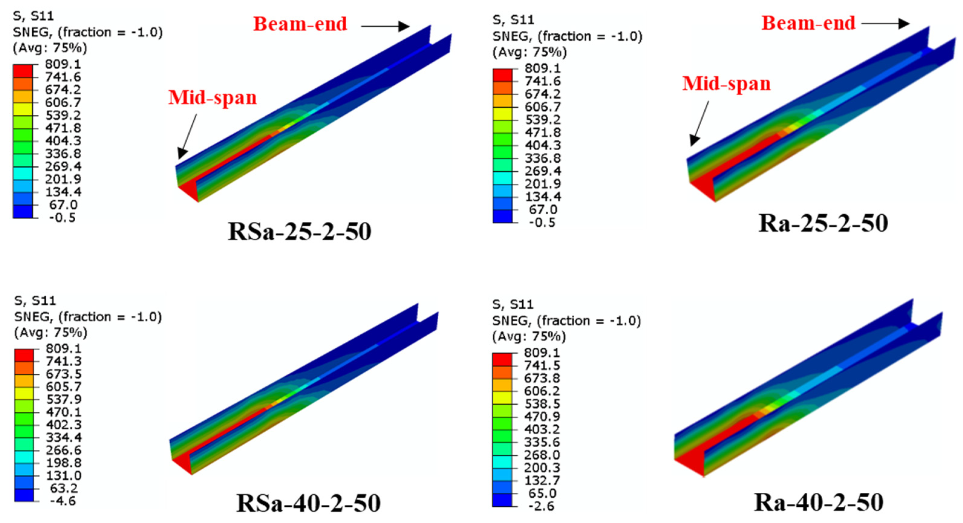
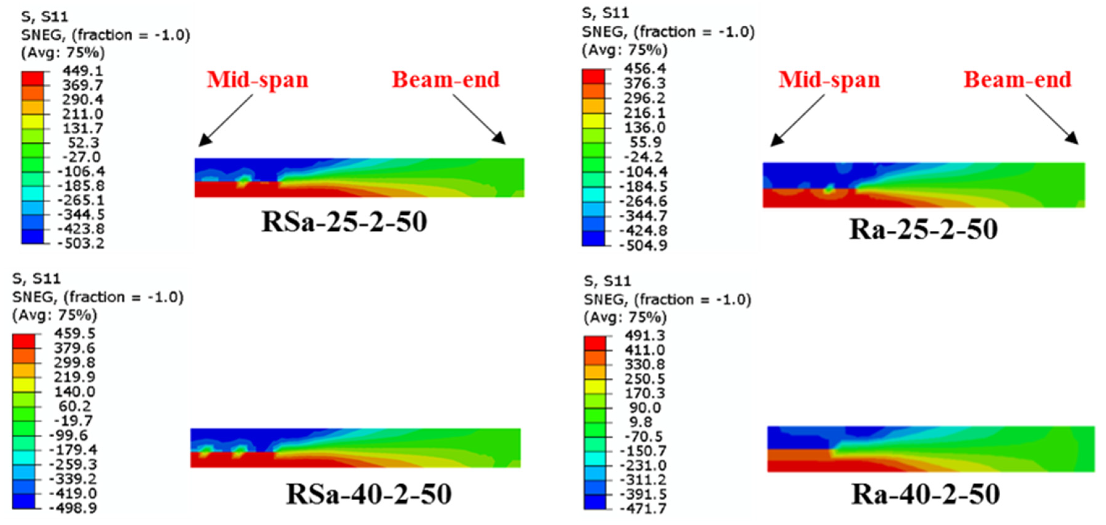
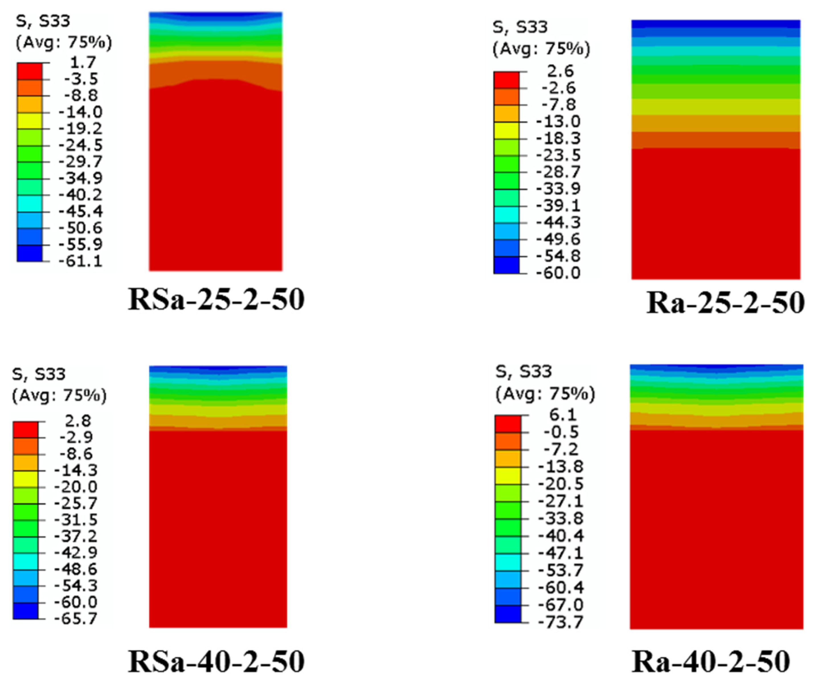
- The influence of varied concrete compressive strengths had a minor impact on the ultimate bending capacity of the RCFST beams when strengthened with multi-CFRP layers. This is due to all the steel tubes being with the compact section classification, which can achieve high confinement to the concrete core, as previously proven in previous experimental studies and also proven numerically in the current study.
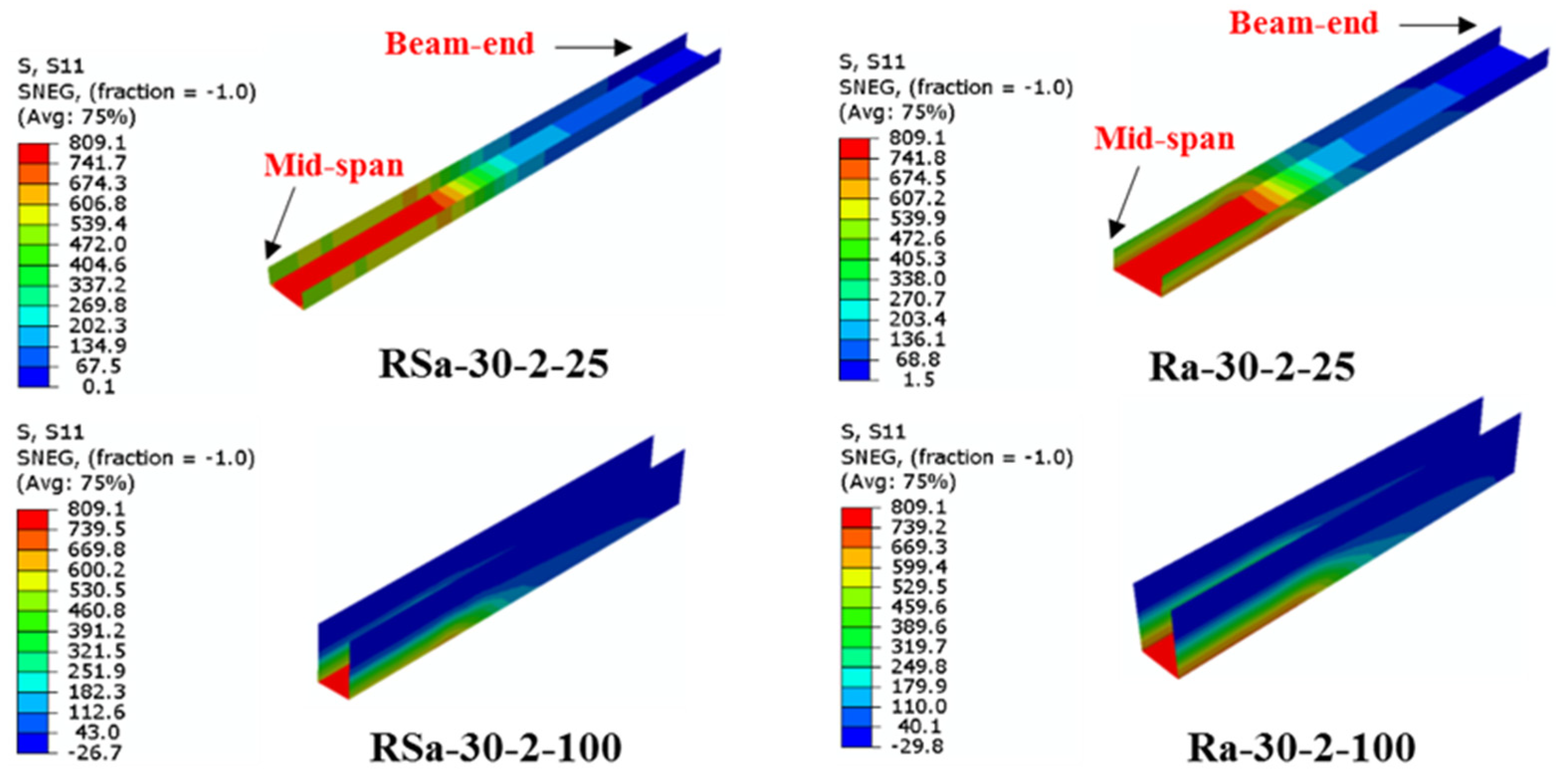
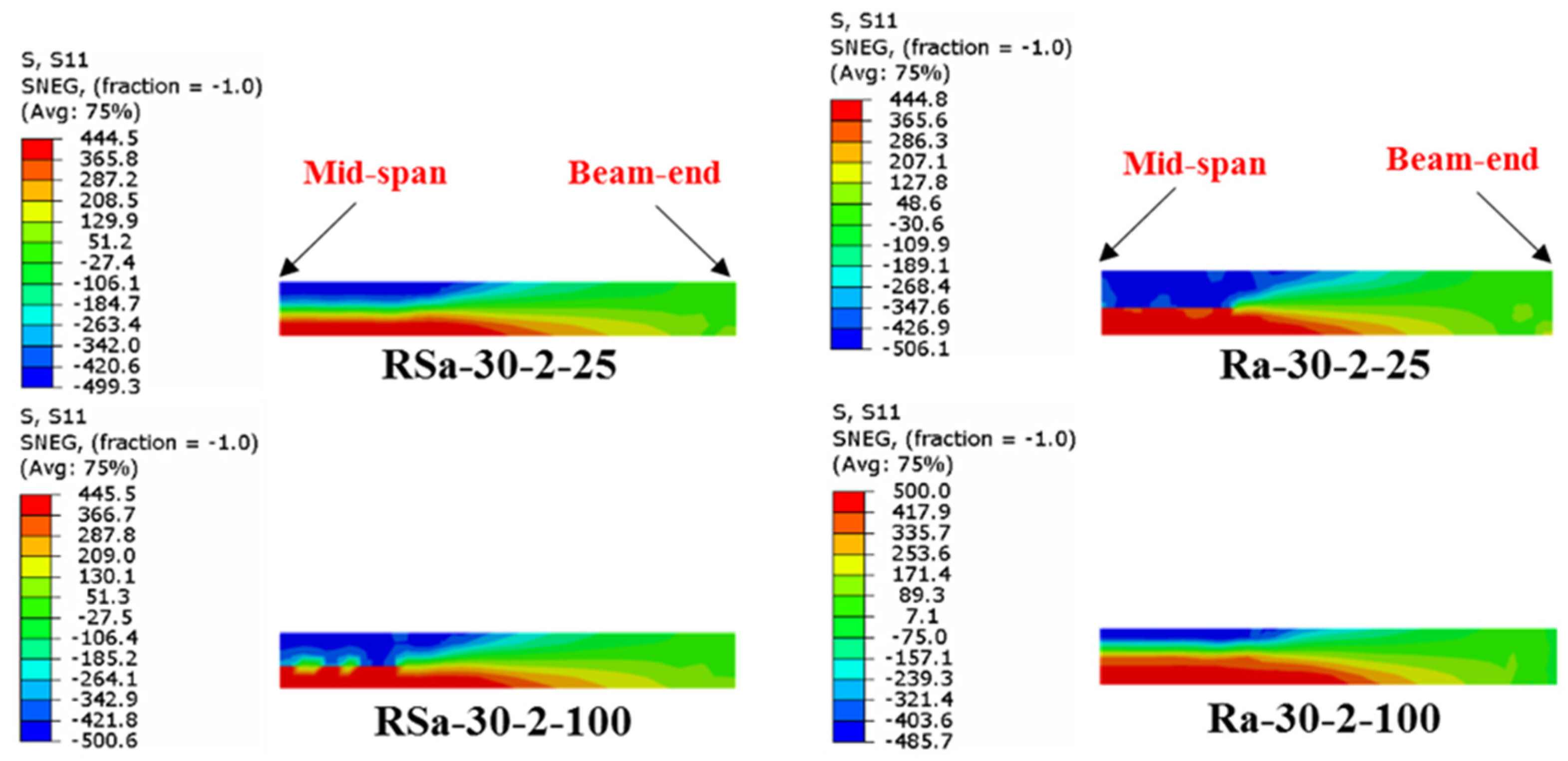
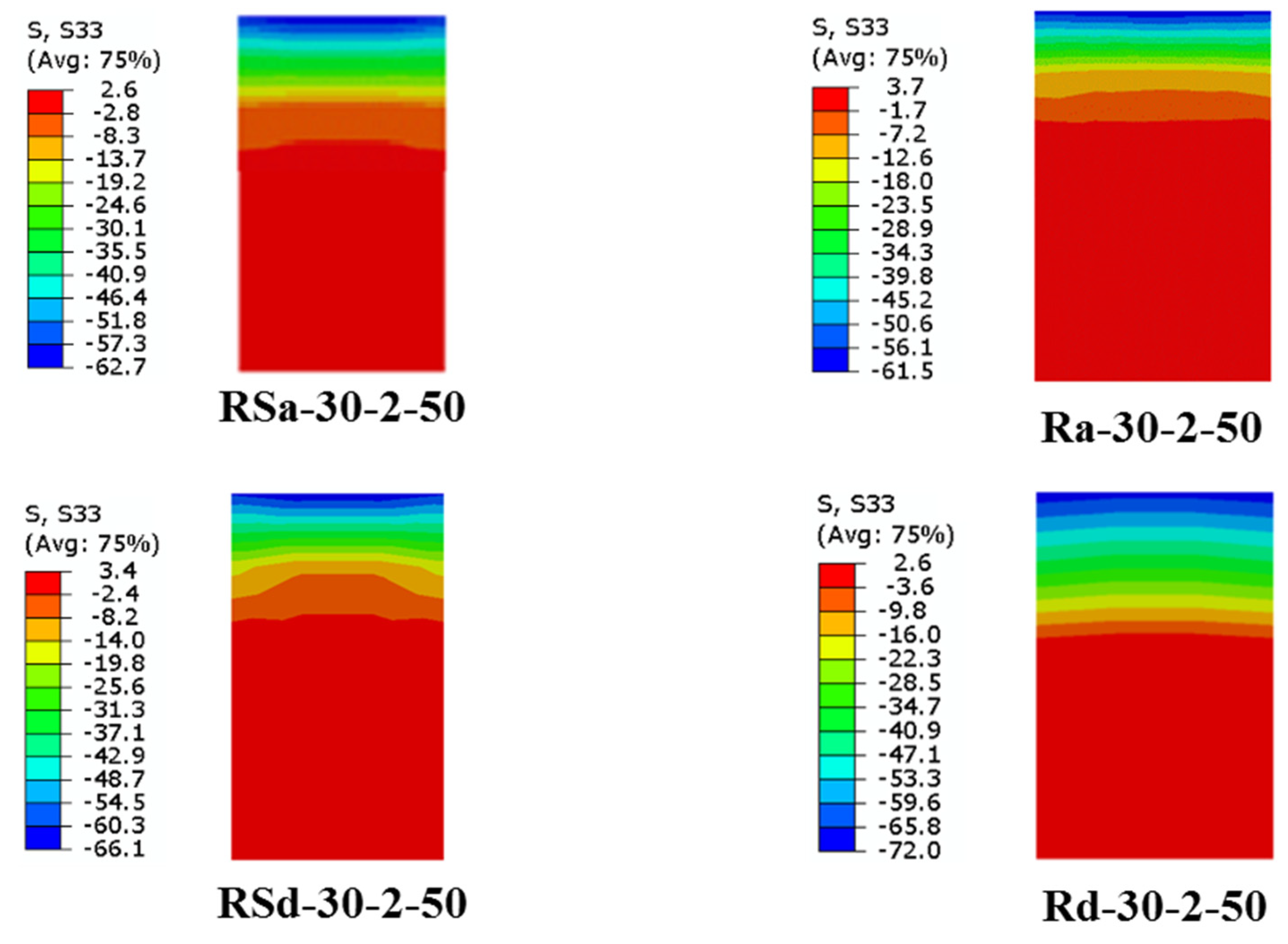
- Unlike the influence of using multi-CFRP layers, increasing the depth of the U-shaped wrapping scheme (wrapping-depth ratio) showed very limited impact on improving the ultimate bending capacity of the strengthened RCFST beams, since the bottom fiber of the U-shaped CFRP patch located at the bottom flange of CFST beam usually carrying much higher tensile stresses than that located at both sides of the beam.
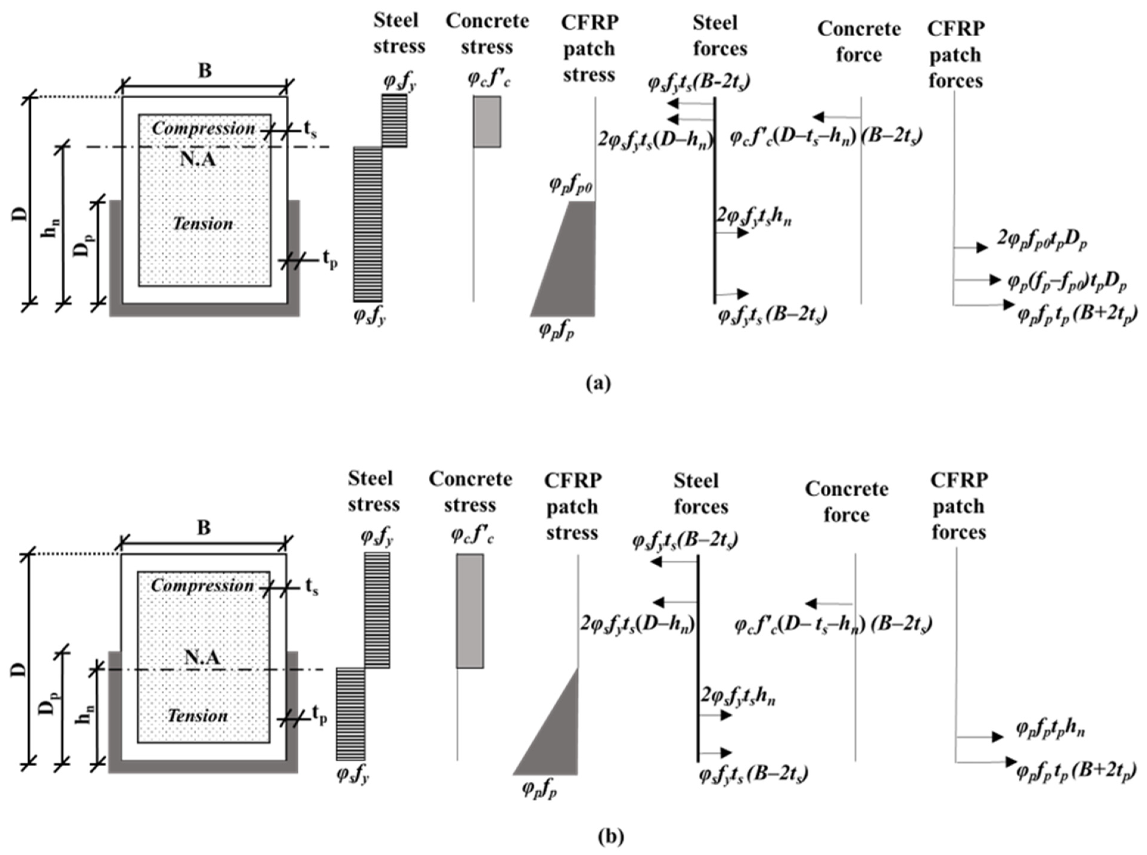
- It was concluded that the proposed theoretical model is reasonably conservative, and it can fairly predict the ultimate bending capacity of the U-CFRP-RCFST beams as the predicted ultimate bending capacity of the U-CFRP-RCFST beams, on average, up to 10% lower compared to the numerical results obtained from the current FE models and existing experimental results. This model is expected to provide engineers with a reliable tool for estimating the most effective wrapping-depth ratio and number of CFRP layers required for strengthening or repairing RCFST beams in practical applications.
Author Contributions
Funding
Data Availability Statement
Acknowledgments
Conflicts of Interest
Nomenclature
References
- Tang, H.; Wang, H.; Liu, Y.; Sun, X.; Huang, X. Behaviour of CFRP Confined Square Concrete-Filled Stainless Steel Tubular Columns under Uni-Axial Compression. Thin-Walled Struct. 2023, 183, 110440. [Google Scholar] [CrossRef]
- Miao, K.; Wei, Y.; Zhang, S.; Zheng, K.; Ding, M. Eccentric Compression Behavior of Concrete-Filled Steel Tube Columns Strengthened by CFRP/Steel Strip. Eng. Struct. 2023, 287, 116191. [Google Scholar] [CrossRef]
- Tao, Z.; Han, L.-H. Behaviour of Fire-Exposed Concrete-Filled Steel Tubular Beam Columns Repaired with CFRP Wraps. Thin-Walled Struct. 2007, 45, 63–76. [Google Scholar] [CrossRef]
- Wang, Q.L.; Shao, Y.B. Flexural Performance of Circular Concrete Filled Cfrp-Steel Tubes. Adv. Steel Constr. 2015, 11, 127–149. [Google Scholar] [CrossRef]
- Al-Zand, A.W.; Badaruzzaman, W.H.W.; Mutalib, A.A.; Hilo, S.J. Rehabilitation and Strengthening of High-Strength Rectangular CFST Beams Using a Partial Wrapping Scheme of CFRP Sheets: Experimental and Numerical Study. Thin-Walled Struct. 2017, 114, 80–91. [Google Scholar] [CrossRef]
- Sundarraja, M.C.; Ganesh Prabhu, G. Finite Element Modelling of CFRP Jacketed CFST Members under Flexural Loading. Thin-Walled Struct. 2011, 49, 1483–1491. [Google Scholar] [CrossRef]
- Sundarraja, M.C.; Prabhu, G.G. Experimental Investigation on Strengthening of CFST Members Under Flexure Using CFRP Fabric. Arab. J. Sci. Eng. 2014, 39, 659–668. [Google Scholar] [CrossRef]
- Al-Zand, A.W.; Badaruzzaman, W.H.W.; Mutalib, A.A.; Hilo, S.J. The Enhanced Performance of CFST Beams Using Different Strengthening Schemes Involving Unidirectional CFRP Sheets: An Experimental Study. Eng. Struct. 2016, 128, 184–198. [Google Scholar] [CrossRef]
- Al-Zand, A.W.; Badaruzzaman, W.H.W.; Mutalib, A.A.; Hilo, S.J. Flexural Behavior of CFST Beams Partially Strengthened with Unidirectional CFRP Sheets: Experimental and Theoretical Study. J. Compos. Constr. 2018, 22, 4018018. [Google Scholar] [CrossRef]
- Du, Y.; Gao, D.; Chen, Z.; Deng, X.; Qian, K. Experimental Study on the Flexural Behavior of Square High-Strength Concrete-Filled Steel Tube Beams with Different CFRP Wrapping Schemes. Compos. Struct. 2023, 304, 116325. [Google Scholar] [CrossRef]
- AISC ANSI/AISC 360-10; Specification for Structural Steel Buildings. American Institute of Steel Construction: Chicago, IL, USA, 2010.
- Eurocode 4 EN 1994; Design of Composite Steel and Concrete Structures. Comité Europeo de Normalización: Brussels, Belgium, 1992.
- AIJ; Recommendations for Design and Construction of Concrete Filled Steel Tubular Structures. Architectural Institute of Japan: Tokyo, Japan, 1997.
- Bong Kwon, Y.; Kyu Jeong, I.; Kwon, Y.B.; Jeong, I.K. Resistance of Rectangular Concrete-Filled Tubular (CFT) Sections to the Axial Load and Combined Axial Compression and Bending. Thin-Walled Struct. 2014, 79, 178–186. [Google Scholar] [CrossRef]
- Lai, Z.; Varma, A.H.; Zhang, K. Noncompact and Slender Rectangular CFT Members: Experimental Database, Analysis, and Design. J. Constr. Steel Res. 2014, 101, 455–468. [Google Scholar] [CrossRef]
- Wang, Q.L.; Li, J.; Shao, Y.B.; Zhao, W.J. Flexural Performances of Square Concrete Filled CFRP-Steel Tubes (S-CF-CFRP-ST). Adv. Struct. Eng. 2015, 18, 1319–1344. [Google Scholar] [CrossRef]
- He, X.; Ke, K.; Zhou, X. Closed-Form Design Solutions for Parallelogram Hollow Structural Sections under Bending Scenarios. J. Constr. Steel Res. 2023, 207, 107934. [Google Scholar] [CrossRef]
- Tahenni, T.; Bouziadi, F.; Boulekbache, B.; Amziane, S. Experimental and Nonlinear Finite Element Analysis of Shear Behaviour of Reinforced Concrete Beams. Structures 2021, 29, 1582–1596. [Google Scholar] [CrossRef]
- Uslu, F.; Taşkın, K. Experimental and Finite Element Method Investigation of Axial Load Carrying Capacity of Concrete Filled Circular Steel Tube Columns According to Different Slenderness Ratios. Int. J. Steel Struct. 2024, 24, 619–634. [Google Scholar] [CrossRef]
- Wang, J.; Cheng, L.; Yang, J. Compressive Behavior of CFRP-Steel Composite Tubed Steel-Reinforced Columns with High-Strength Concrete. J. Constr. Steel Res. 2018, 150, 354–370. [Google Scholar] [CrossRef]
- Ansari, M.; Jeddi, M.Z.; Badaruzzaman, W.H.W.; Tahir, M.M.; Osman, S.A.; Hosseinpour, E. A Numerical Investigation on the through Rib Stiffener Beam to Concrete-Filled Steel Tube Column Connections Subjected to Cyclic Loading. Eng. Sci. Technol. Int. J. 2021, 24, 728–735. [Google Scholar] [CrossRef]
- Choi, I.R.; Chung, K.S.; Kim, C.S. Experimental Study on Rectangular CFT Columns with Different Steel Grades and Thicknesses. J. Constr. Steel Res. 2017, 130, 109–119. [Google Scholar] [CrossRef]
- Eurocode 2 EN 1992-1-1; Design of Concrete Structures-Part 1-1: General Ruels and Rules for Buildings. Comité Europeo de Normalización: Brussels, Belgium, 2004.
- Wang, T.; Hsu, T.T.C. Nonlinear Finite Element Analysis of Concrete Structures Using New Constitutive Models. Comput. Struct. 2001, 79, 2781–2791. [Google Scholar] [CrossRef]
- Systèmes, D. Abaqus 6.10: Analysis User’s Manual. Provid; RI Dassault Systèmes Simulia Corp.: Vélizy-Villacoublay, France, 2010. [Google Scholar]
- Fawzia, S.; Al-Mahaidi, R.; Zhao, X.-L. Experimental and Finite Element Analysis of a Double Strap Joint between Steel Plates and Normal Modulus CFRP. Compos. Struct. 2006, 75, 156–162. [Google Scholar] [CrossRef]
- Al-Zubaidy, H.; Al-Mahaidi, R.; Zhao, X.-L. Finite Element Modelling of CFRP/Steel Double Strap Joints Subjected to Dynamic Tensile Loadings. Compos. Struct. 2013, 99, 48–61. [Google Scholar] [CrossRef]
- Bsisu, K.A.-D.; Hussein, H.H.; Sargand, S.M. The Use of Hashin Damage Criteria, CFRP–Concrete Interface and Concrete Damage Plasticity Models in 3D Finite Element Modeling of Retrofitted Reinforced Concrete Beams with CFRP Sheets. Arab. J. Sci. Eng. 2017, 42, 1171–1184. [Google Scholar] [CrossRef]
- Moldovan, I.-F.; Nedelcu, M.; Buru, S.-M. Analysing the Performance of Hollow Core Slabs Strengthened with CFRP. In IOP Conference Series: Materials Science and Engineering; IOP Publishing: Prague, Czech Republic, 2021; Volume 1203, p. 32056. [Google Scholar]






| Specimen’s Label | D × B × ts (mm) | fcu (MPa) | CFRP Layers | η (%) | MEX (kN.m) | MFE (kN.m) | MFE/MEx | Ref. |
|---|---|---|---|---|---|---|---|---|
| RS | 125 × 75 × 2.8 | 31.5 | 0 | 0 | 22.7 | 22.49 | 0.99 | [8] |
| RS-100P-2L | 125 × 75 × 2.8 | 31.5 | 2 | 50 | 29.3 | 28.56 | 0.97 | |
| RS-100P-3L | 125 × 75 × 2.8 | 31.5 | 3 | 50 | 32.0 | 30.40 | 0.95 | |
| R | 150 × 100 × 3.7 | 31.5 | 0 | 0 | 40.6 | 42.37 | 1.04 | [9] |
| R-100P-2L | 150 × 100 × 3.7 | 31.5 | 2 | 50 | 49.1 | 51.17 | 1.04 | |
| MV | 1.00 | |||||||
| SD | 0.04 | |||||||
| D × B × ts (mm) | Modulus of Elasticity Es (GPa) | Yield Strength fy (MPa) | Ultimate Tensile Strength fu (MPa) | Elongation (%) | Ref. |
|---|---|---|---|---|---|
| 125 × 75 × 2.8 | 205.6 | 445.6 | 482.3 | 15.4 | [8] |
| 150 × 100 × 3.7 | 194.0 | 444.0 | 531.0 | 19.9 | [9] |
| Dilation Angle | Eccentricity | fb0/fc0 | K | Viscosity |
|---|---|---|---|---|
| 40 | 0.1 | 1.16 | 0.667 | 0.0001 |
| FE Model’s Label | D × B × ts (mm) | n | η (%) | fcu (MPa) | fy (MPa) | MFE (kN.m) | Mu−Th (kN.m) | Mu−Th/MFE |
|---|---|---|---|---|---|---|---|---|
| RSa-30 | 125 × 75 × 2.8 | 0 | 0 | 31.5 | 445.6 | 22.5 | 20.3 | 0.90 |
| RSa-30-1-50 | 125 × 75 × 2.8 | 1 | 50 | 31.5 | 445.6 | 25.5 | 24.6 | 0.96 |
| RSa-30-2-50 | 125 × 75 × 2.8 | 2 | 50 | 31.5 | 445.6 | 28.6 | 27.6 | 0.97 |
| RSa-30-3-50 | 125 × 75 × 2.8 | 3 | 50 | 31.5 | 445.6 | 30.4 | 30.2 | 0.99 |
| RSa-30-4-50 | 125 × 75 × 2.8 | 4 | 50 | 31.5 | 445.6 | 32.1 | 32.4 | 1.01 |
| RSa-25-2-50 | 125 × 75 × 2.8 | 2 | 50 | 25.0 | 445.6 | 28.2 | 27.0 | 0.96 |
| RSa-35-2-50 | 125 × 75 × 2.8 | 2 | 50 | 35.0 | 445.6 | 28.7 | 28.0 | 0.98 |
| RSa-40-2-50 | 125 × 75 × 2.8 | 2 | 50 | 40.0 | 445.6 | 28.9 | 28.4 | 0.98 |
| RSa-30-2-25 | 125 × 75 × 2.8 | 2 | 25 | 31.5 | 445.6 | 28.2 | 27.5 | 0.98 |
| RSa-30-2-75 | 125 × 75 × 2.8 | 2 | 75 | 31.5 | 445.6 | 28.3 | 27.6 | 0.98 |
| RSa-30-2-100 | 125 × 75 × 2.8 | 2 | 100 | 31.5 | 445.6 | 28.6 | 27.6 | 0.97 |
| RSb-30-2-50 | 125 × 75 × 2.8 | 2 | 50 | 31.5 | 355.0 | 23.7 | 24.8 | 1.05 |
| RSc-30-2-50 | 125 × 75 × 2.8 | 2 | 50 | 31.5 | 275.0 | 20.2 | 21.4 | 1.06 |
| RSd-30-2-50 | 125 × 75 × 2.8 | 2 | 50 | 31.5 | 235.0 | 18.5 | 19.5 | 1.05 |
| Ra-30 | 150 × 100 × 3.7 | 0 | 0 | 31.5 | 444.0 | 42.4 | 40.6 | 0.96 |
| Ra-30-1-50 | 150 × 100 × 3.7 | 1 | 50 | 31.5 | 444.0 | 49.9 | 47.7 | 0.96 |
| Ra-30-2-50 | 150 × 100 × 3.7 | 2 | 50 | 31.5 | 444.0 | 51.2 | 52.6 | 1.03 |
| Ra-30-3-50 | 150 × 100 × 3.7 | 3 | 50 | 31.5 | 444.0 | 56.9 | 56.9 | 1.00 |
| Ra-30-4-50 | 150 × 100 × 3.7 | 4 | 50 | 31.5 | 444.0 | 59.5 | 60.7 | 1.02 |
| Ra-25-2-50 | 150 × 100 × 3.7 | 2 | 50 | 25.0 | 444.0 | 50.5 | 51.4 | 1.02 |
| Ra-35-2-50 | 150 × 100 × 3.7 | 2 | 50 | 35.0 | 444.0 | 51.2 | 53.1 | 1.04 |
| Ra-40-2-50 | 150 × 100 × 3.7 | 2 | 50 | 40.0 | 444.0 | 51.5 | 53.9 | 1.05 |
| Ra-30-2-25 | 150 × 100 × 3.7 | 2 | 25 | 31.5 | 444.0 | 51.0 | 52.2 | 1.02 |
| Ra-30-2-75 | 150 × 100 × 3.7 | 2 | 75 | 31.5 | 444.0 | 51.3 | 52.6 | 1.03 |
| Ra-30-2-100 | 150 × 100 × 3.7 | 2 | 100 | 31.5 | 444.0 | 52.2 | 52.6 | 1.01 |
| Rb-30-2-50 | 150 × 100 × 3.7 | 2 | 50 | 31.5 | 355.0 | 47.5 | 44.8 | 0.94 |
| Rc-30-2-50 | 150 × 100 × 3.7 | 2 | 50 | 31.5 | 275.0 | 39.9 | 37.8 | 0.95 |
| Rd-30-2-50 | 150 × 100 × 3.7 | 2 | 50 | 31.5 | 235.0 | 36.8 | 34.4 | 0.93 |
| MV | 0.99 | |||||||
| SD | 0.04 | |||||||
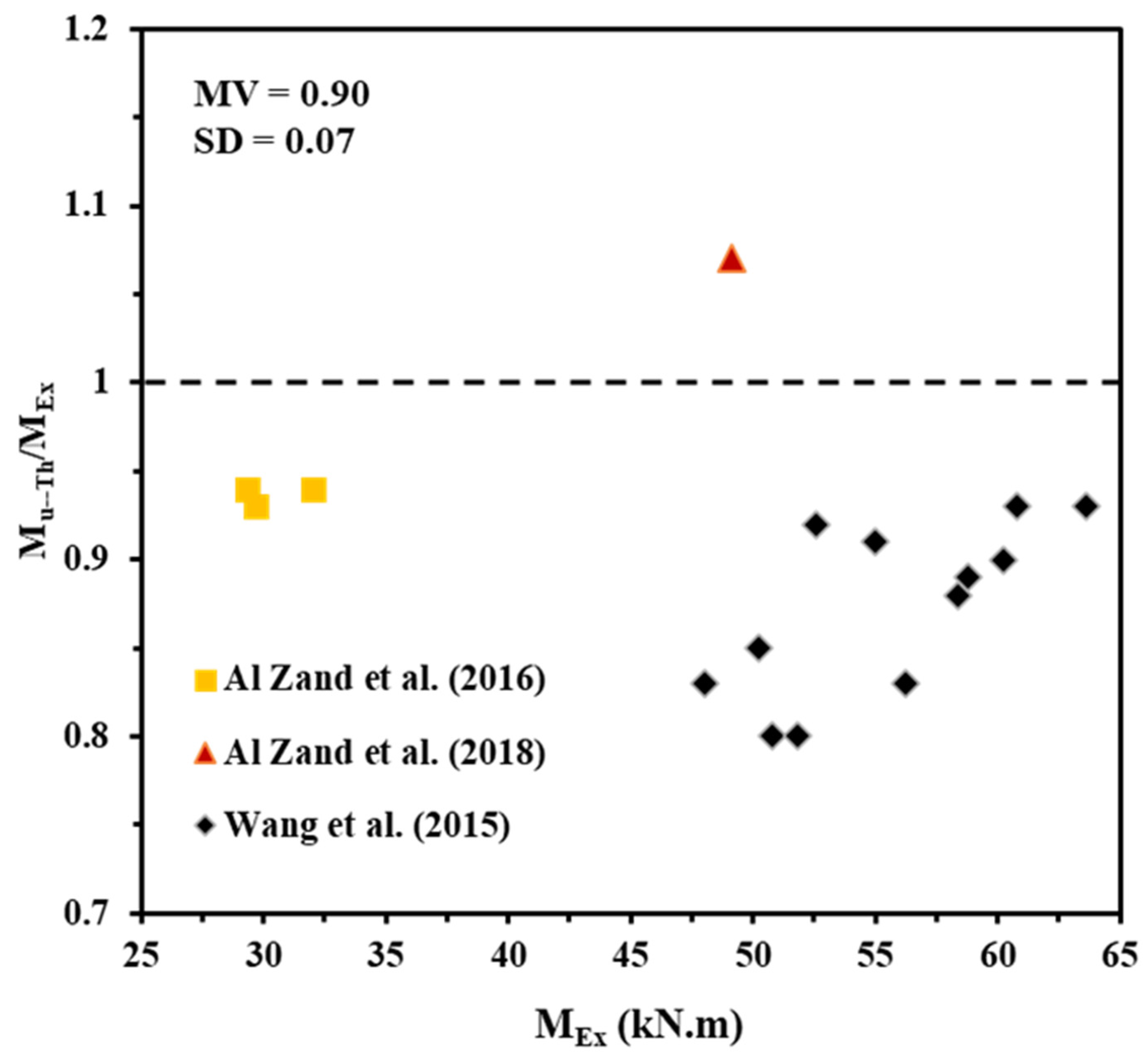
| Experimental Specimen’s Label | D × B × ts (mm) | fy (MPa) | fcu (MPa) | n | η (%) | Wrapping Scheme | MEx (kN.m) | Mu−Th (kN.m) | Mu−Th/MEx |
|---|---|---|---|---|---|---|---|---|---|
| RS-F100-2L | 125 × 75 × 2.8 | 445.6 | 31.5 | 2 | 100 | Full | 29.7 | 27.64 | 0.93 |
| RS-P100-2L | 125 × 75 × 2.8 | 445.6 | 31.5 | 2 | 50 | U-shaped | 29.3 | 27.64 | 0.94 |
| RS-P100-3L | 125 × 75 × 2.8 | 445.6 | 31.5 | 3 | 50 | U-shaped | 32 | 30.22 | 0.94 |
| R-P100-2L | 150 × 100 × 3.7 | 444 | 31.5 | 2 | 50 | U-shaped | 49.1 | 52.57 | 1.07 |
| SB A-1 | 140 × 140 × 3.5 | 300 | 33 | 1 | 100 | Full | 48 | 39.85 | 0.83 |
| SB A-2 | 140 × 140 × 3.5 | 300 | 33 | 2 | 100 | Full | 56.2 | 46.89 | 0.83 |
| SB A-3 | 140 × 140 × 3.5 | 300 | 33 | 3 | 100 | Full | 58.8 | 52.51 | 0.89 |
| SB B-1 | 140 × 140 × 3.5 | 300 | 39.4 | 1 | 100 | Full | 50.8 | 40.64 | 0.80 |
| SB B-2 | 140 × 140 × 3.5 | 300 | 39.4 | 2 | 100 | Full | 52.6 | 48.18 | 0.92 |
| SB B-3 | 140 × 140 × 3.5 | 300 | 39.4 | 3 | 100 | Full | 60.2 | 54.34 | 0.90 |
| SB C-1 | 140 × 140 × 3.5 | 300 | 49 | 1 | 100 | Full | 51.8 | 41.64 | 0.80 |
| SB C-2 | 140 × 140 × 3.5 | 300 | 49 | 2 | 100 | Full | 55 | 49.84 | 0.91 |
| SB C-3 | 140 × 140 × 3.5 | 300 | 49 | 3 | 100 | Full | 60.8 | 56.71 | 0.93 |
| SB D-1 | 140 × 140 × 3.5 | 300 | 59.7 | 1 | 100 | Full | 50.2 | 42.56 | 0.85 |
| SB D-2 | 140 × 140 × 3.5 | 300 | 59.7 | 2 | 100 | Full | 58.4 | 51.37 | 0.88 |
| SB D-3 | 140 × 140 × 3.5 | 300 | 59.7 | 3 | 100 | Full | 63.6 | 58.93 | 0.93 |
| MV | 0.90 | ||||||||
| SD | 0.07 | ||||||||
Disclaimer/Publisher’s Note: The statements, opinions and data contained in all publications are solely those of the individual author(s) and contributor(s) and not of MDPI and/or the editor(s). MDPI and/or the editor(s) disclaim responsibility for any injury to people or property resulting from any ideas, methods, instructions or products referred to in the content. |
© 2025 by the authors. Licensee MDPI, Basel, Switzerland. This article is an open access article distributed under the terms and conditions of the Creative Commons Attribution (CC BY) license (https://creativecommons.org/licenses/by/4.0/).
Share and Cite
Ansari, M.; Al Zand, A.W.; Hosseinpour, E.; Joharchi, A.; Abedini, M. Development of a Stress Block Model to Predict the Ultimate Bending Capacity of Rectangular Concrete-Filled Steel Tube Beams Strengthened with U-Shaped CFRP Sheets. Infrastructures 2025, 10, 73. https://doi.org/10.3390/infrastructures10040073
Ansari M, Al Zand AW, Hosseinpour E, Joharchi A, Abedini M. Development of a Stress Block Model to Predict the Ultimate Bending Capacity of Rectangular Concrete-Filled Steel Tube Beams Strengthened with U-Shaped CFRP Sheets. Infrastructures. 2025; 10(4):73. https://doi.org/10.3390/infrastructures10040073
Chicago/Turabian StyleAnsari, Mohammad, Ahmed W. Al Zand, Emad Hosseinpour, Ali Joharchi, and Masoud Abedini. 2025. "Development of a Stress Block Model to Predict the Ultimate Bending Capacity of Rectangular Concrete-Filled Steel Tube Beams Strengthened with U-Shaped CFRP Sheets" Infrastructures 10, no. 4: 73. https://doi.org/10.3390/infrastructures10040073
APA StyleAnsari, M., Al Zand, A. W., Hosseinpour, E., Joharchi, A., & Abedini, M. (2025). Development of a Stress Block Model to Predict the Ultimate Bending Capacity of Rectangular Concrete-Filled Steel Tube Beams Strengthened with U-Shaped CFRP Sheets. Infrastructures, 10(4), 73. https://doi.org/10.3390/infrastructures10040073


