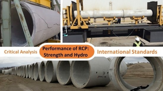
Critical Analysis of International Precast Concrete Pipe Standards
Abstract
:1. Introduction
1.1. Reinforced Concrete Pipe Development
1.2. Competition from Flexible Pipe Industry
1.3. Hydrostatic Performance Challenges
1.4. Bio-Corrosion Challenges
1.5. Scope of Study
1.6. Selection of Study Area
1.7. Terminology and Unit of Measure
2. Products and Materials Requirements
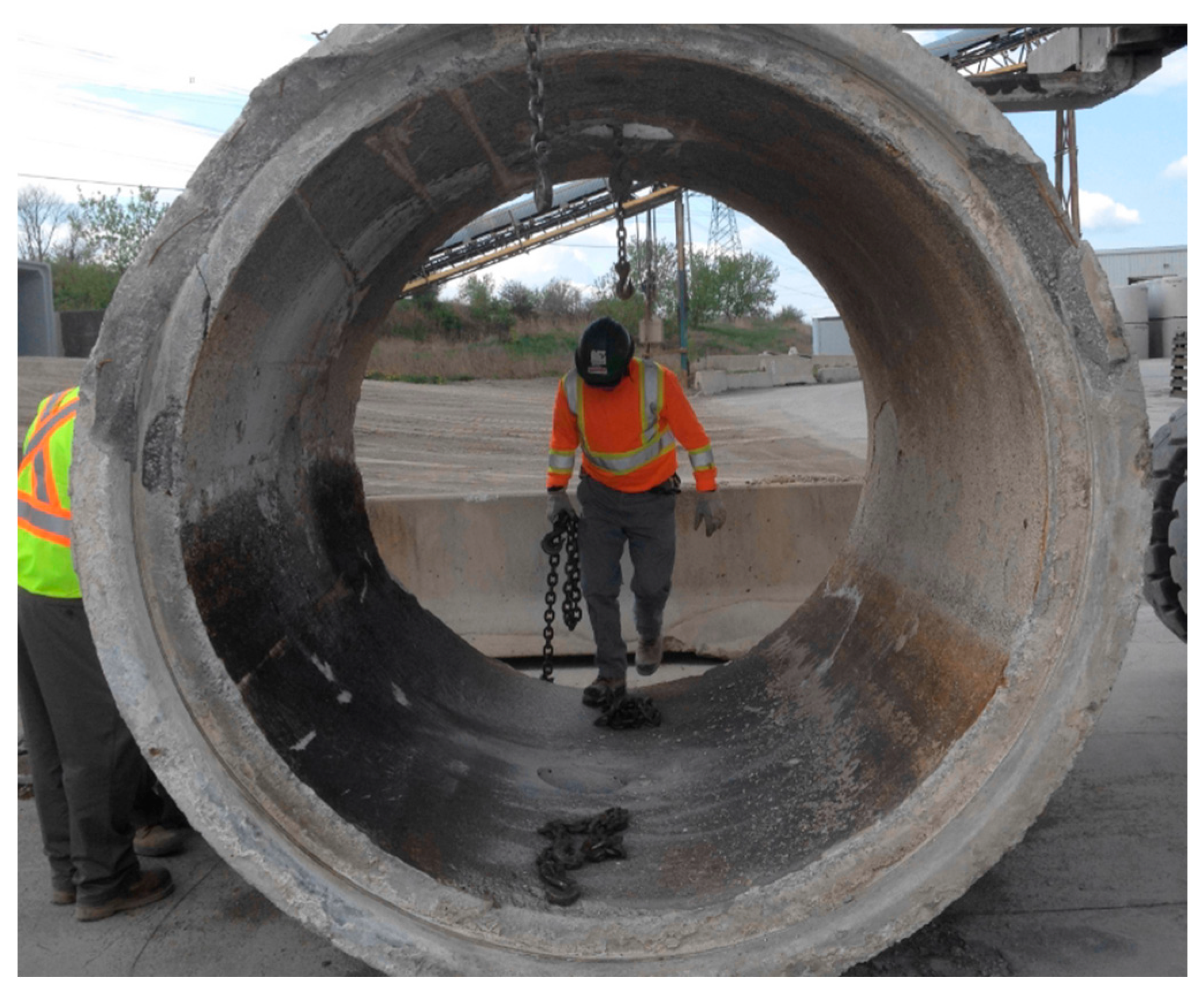
2.1. Geometrical Requirements
2.2. Concrete for Precast Pipe
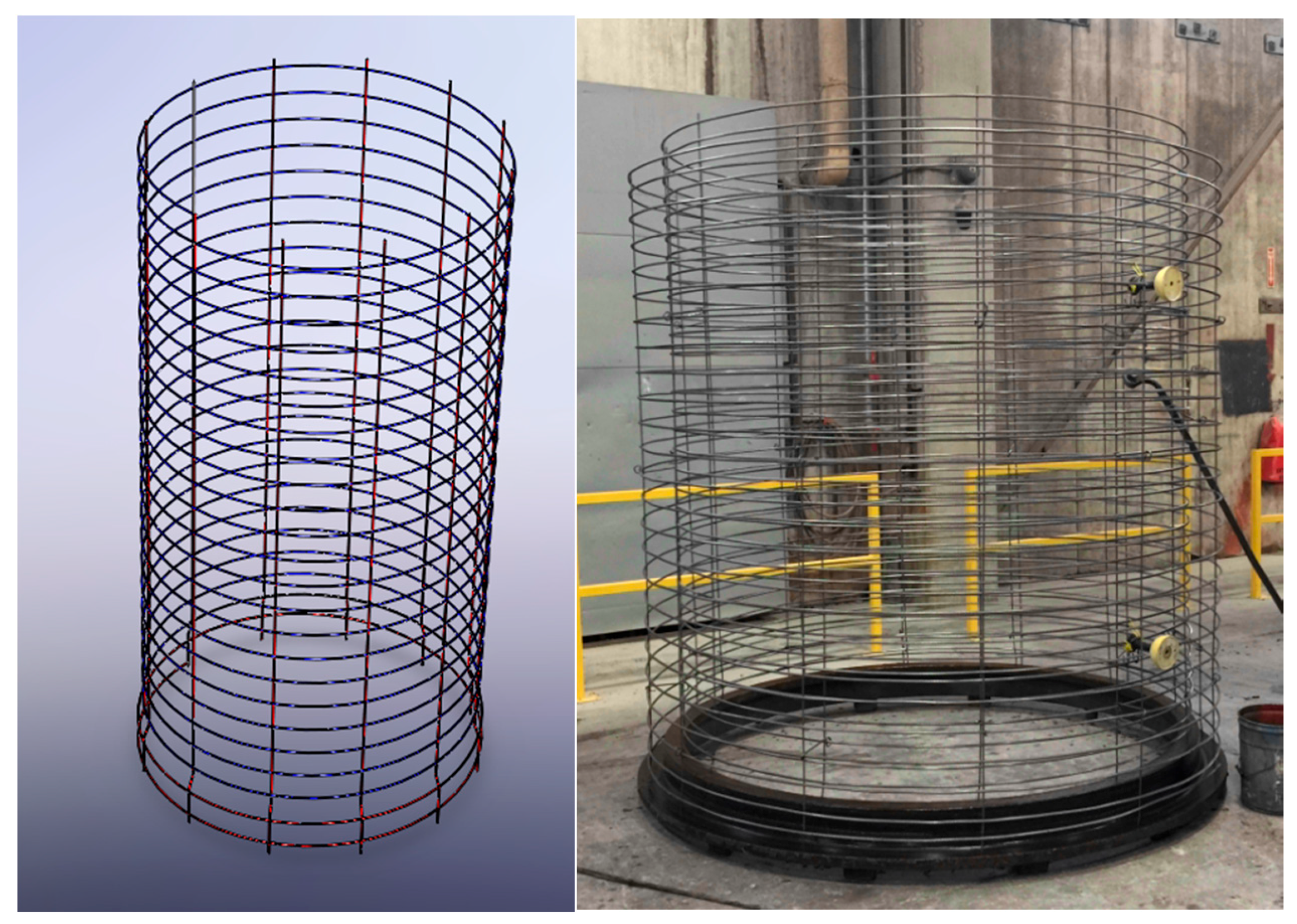
2.3. Conventional Reinforcement and Concrete Cover
3. Product Strength Evaluation
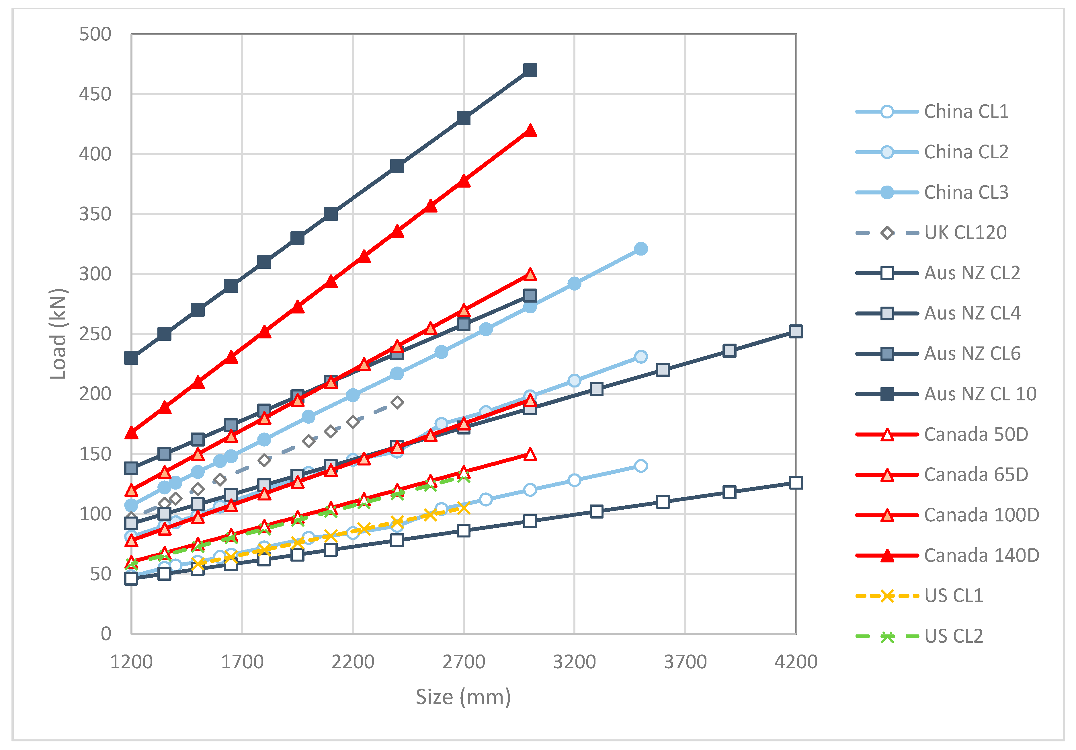
3.1. Pipe Strength Classification
3.2. Structural Load Test
3.2.1. Canada and US
3.2.2. United Kingdom
3.2.3. Australia and New Zealand
3.2.4. China
4. Hydrostatic Performance and Joint Design
4.1. Pipe Hydrostatic Performance in Canada
4.2. Pipe Hydrostatic Performance in US
4.3. Pipe Hydrostatic Performance in Australia and New Zealand
4.4. Pipe Hydrostatic Performance in UK
4.5. Pipe Hydrostatic Performance in China
5. Concrete Pipe Durability
5.1. Absorption Test
5.2. Crack Width
5.3. Concrete Cover
6. Discussion and Recommendations
6.1. Concrete Cover and Crack Limit
6.2. Load Test
6.3. Hydrostatic Performance Test
6.4. Durability
7. Conclusions
Author Contributions
Funding
Acknowledgments
Conflicts of Interest
References
- Ontario Concrete Pipe Association (OCPA). Concrete Pipe Design Manual; OCPA: Kitchener, ON, Canada.
- Schladweiler, J.C. The History of Sanitary Sewer. 2017. Available online: http://www.sewerhistory.org/ (accessed on 14 June 2018).
- Marston, A.; Anderson, A.O. The Theory of Loads on Pipes in Ditches and Test of Cement and Clay Drain Tile and Sewer Pipe; Iowa State College of Agriculture and Mechanic Arts: Ames, IA, USA, 1931. [Google Scholar]
- Orlander, H.C. Stress Analysis of Concrete Pipe; Engineering Monograph No. 6; US Bureau of Reclamation: Washington, DC, USA, 1950. [Google Scholar]
- Spangler, M. Soil Engineering; International Textbook Company: Scranton, PA, USA, 1960. [Google Scholar]
- Heger, F. Structural Behaviour of Circular Reinforced Concrete Pipe—Development of Theory. J. Proc. 1963, 60, 1567–1614. [Google Scholar]
- Heger, F.; Gillespie, J. Design of Circular Concrete Pipe Reinforced with Welded Deformed Wire Fabric; Transportation Research Board: Washington, DC, USA, 1967. [Google Scholar]
- American Society of Civil Engineers (ASCE). Standard Practice for Direct Design of Buried Precast Concrete Pipe Using Standard Installation; ASCE15; ASCE: Reston, VA, USA, 1993. [Google Scholar]
- American Association of State Highway and Transportation Officials (AASHTO). LRFD Bridge Design Specification; AASHTO: Washington, DC, USA, 2014. [Google Scholar]
- CSA Group. Canadian Highway Bridge Design Code; CSA S6; CSA Group: Mississauga, ON, Canada, 2014. [Google Scholar]
- British Standards Institution (BSI). Concrete Pipes and Fittings, Unreinforced, Steel Fibre and Reinforced; BS EN 1916:2002; BSI: London, UK, 2002. [Google Scholar]
- ASTM International. Standard Specification for Steel Fiber Reinforced Concrete Culvert, Storm Drain, and Sewer Pipe; ASTM C1765; ASTM International: West Conshohocken, PA, USA, 2013. [Google Scholar]
- ASTM International. Standard Specification for Synthetic Fiber Reinforced Concrete Culvert, Storm Drain, and Sewer Pipe; ASTM C1818: ASTM International: West Conshohocken, PA, USA, 2015. [Google Scholar]
- Mohamed, N.; Soliman, A.M.; Nehdi, M.L. Utilization of steel fibres in precast concrete pipes. In Proceedings of the TAC 2012. Tunnel and Underground Space: Sustainability and Innovations, Montreal, QC, Canada, 17 October 2012; (TAC Paper 158). Transportation Association of Canada: Ottawa, ON, Canada, 2012. [Google Scholar]
- Mohamed, N.; Soliman, A.M.; Nehdi, M.L. Full-scale pipes using dry-cast steel fibre-reinforced concrete. Constr. Build. Mater. 2012, 72, 411–422. [Google Scholar] [CrossRef]
- Mohamed, N.; Soliman, A.M.; Nehdi, M.L. Mechanical performance of full-scale precast steel fibre-reinforced concrete pipes. Eng. Struct. 2012, 84, 287–299. [Google Scholar] [CrossRef]
- Mohamed, N.; Nehdi, M.L. Rational finite element assisted design of precast steel fibre-reinforced concrete pipes. Eng. Struct. 2012, 124, 196–206. [Google Scholar] [CrossRef]
- Lester, H.G. Corrugated Polyethylene Pipe Design Manual & Installation Guide; Plastic Pipe Institute: Irving, TX, USA, 2017. [Google Scholar]
- Curran, S.D. Fiberglass Pipe Past, Present and Future; Fiber Glass Tank and Pipe Institute: Houston, TX, USA, 2013. [Google Scholar]
- Walker, R. The Early History of PVC Pipe.1990. Available online: https://theplumber.com/early-history-of-pvc-pipe/ (accessed on 21 June 2018).
- Rinker Materials. Corrugated Steel Pipe. 1994. Available online: https://www.google.com/url?sa=t&rct=j&q=&esrc=s&source=web&cd=2&cad=rja&uact=8&ved=0ahUKEwi7o6-3yubbAhXVA4gKHXtJCGIQFggqMAE&url=https%3A%2F%2Fwww.rinkerpipe.com%2FTechnicalInfo%2Ffiles%2FInfoBriefs%2FIS304CorrugatedSteelPipe.pdf&usg=AOvVaw2tKXPVnfeH7LlycUpm4-cM (accessed on 21 June 2018).
- Ministry of Transportation Ontario. MTO Gravity Pipe Design Guideline; Ministry of Transportation Ontario: St. Catharines, ON, Canada, 2007. [Google Scholar]
- Pratt, C.; Yang, H.; Hodkiewicz, M. Factors Influencing Pipe Failures in the West Australia Environment. 2011. Available online: https://ceed.wa.edu.au/wp-content/uploads/2017/02/Christopher.Pratt_pdf (accessed on 21 June 2018).
- Parker, C.D. The Corrosion of Concrete. The Sewage Branch of the Melbourne and Metropolitan Board of Works. Aust. J. Exp. Biol. Med. Sci. 1945, 23, 81–90. [Google Scholar] [CrossRef]
- Wu, L.; Hu, C.; Liu, W. The sustainability of Concrete in Sewer Tunnel—A Narrative Review of Acid Corrosion in the City of Edmonton Canada. Sustainability 2018, 10, 517. [Google Scholar] [CrossRef]
- Vollertsen, J.; Nielsen, A.H.; Jensen, H.S.; Rudelle, E.A.; Hvitved-Jacobsen, T. Modeling the Corrosion of Concrete Sewer. In Proceedings of the 12th International Conference on Urban Drainage, Porto Alegre, Brazil, 11–16 September 2011. [Google Scholar]
- Sulikowski, J.; Kozubal, J. The Durability of a Concrete Sewer Pipeline Under Deterioration by Sulphate and Chloride Corrosion. Procedia Eng. 2016, 153, 698–705. [Google Scholar] [CrossRef]
- Bielefeldt, A.; Gutierrez-Padilla, M.G.; Ovtchinnikov, S.; Silverstein, J.; Hernandez, M. Backterial Kinetics of Sulfur Oxidizing Bacteria and Their Biodeterioration Rates of Concrete Sewer Pipe Samples. J. Environ. Eng. 2017, 136, 731–738. [Google Scholar] [CrossRef]
- Population Reference Bureau. 2013 World Population Data Sheet; Population Reference Bureau: Washington, DC, USA, 2013. [Google Scholar]
- Australian Standard. Precast Concrete Pipes (Pressure and Non-Pressure); AS/NZS 4058; Environmental Health Directorate: East Perth, Australia, 2007. [Google Scholar]
- Carleton, E.; Hiner, S.; Kurdziel, J. The History and Application of the Three-Edge Bearing Test for Concrete Pipe. In Concrete Pipe and Box Culverts; Meyerand, J.J., Beakley, J., Eds.; ASTM STP1601; ASTM International: West Conshohocken, PA, USA, 2017; pp. 18–27. [Google Scholar]
- CSA Group. Standards for Concrete Pipe and Manhole Sections; CSA A257; CSA Group: Mississauga, ON, Canada, 2014. [Google Scholar]
- ASTM International. Standard Test Methods for Concrete Pipe, Manhole Sections, or Tile; ASTM C497; ASTM International: West Conshohocken, PA, USA, 2015. [Google Scholar]
- Test Methods of Concrete and Reinforced Concrete Drainage and Sewer Pipe; GB/T 16752; Standardization Administration of the People’s Republic of China: Beijing, China, 2006.
- ASTM International. Standard Specification for Reinforced Concrete Culvert, Storm Drain, and Sewer Pipe; ASTM C76; ASTM International: West Conshohocken, PA, USA, 2016. [Google Scholar]
- ASTM International. Standard Specification for Joints for Concrete Pipe and Manholes, Using Rubber Gasket; ASTM C443; ASTM International: West Conshohocken, PA, USA, 2012. [Google Scholar]
- ASTM International. Standard Specification for Joints for Concrete Pipe, Manholes, and Precast Box Sections Using Preformed Flexible Joint Sealants; ASTM C990; ASTM International: West Conshohocken, PA, USA, 2009. [Google Scholar]
- ASTM International. Standard Specification for Joints for Concrete Gravity Flow Sewer Pipe, Using Rubber Gaskets; ASTM C1628; ASTM International: West Conshohocken, PA, USA, 2017. [Google Scholar]
- Marr, J. A Research Plan and Report on Factors Affecting Culvert Pipe Service Life in Minnesota; Minnesota Department of Transportation: Saint Paul, MN, USA, 2012. [Google Scholar]
- American Concrete Pipe Association. Cracks in Installed Reinforced Concrete Pipe; American Concrete Pipe Association: Irving, TX, USA, 2007. [Google Scholar]
- Busba, E.R.; Sagues, A.A.; Mullins, G. Reinforced Concrete Pipe Cracks—Acceptance Criteria; University of South Florida: Tampa, FL, USA, 2009. [Google Scholar]
- De Schutter, G.; Audenaert, K. Evaluation of water absorption of concrete as a measure for resistance against carbonation and chloride migration. Mater. Struct. 2004, 37, 591–596. [Google Scholar] [CrossRef]
- Environmental Protection Agency (EPA). Process Design Manual for Sulfide Control in Sanitary Sewerage System; Environmental Protection Agency: Washington, DC, USA, 1974. [Google Scholar]




| Pipe Materials | Size Range (mm) | Length (m) | Introduced | Joint | Source |
|---|---|---|---|---|---|
| Polypropylene Pipe | 300–1500 | 4–6 | NA | 10.8 psi @ 1000 h | ADS SaniTite HP |
| Corrugated Polyethylene | 100–1500 | 1987 | Watertight | ADS N-12WT | |
| HDPE | 100–900 | 6–10 | 1960s [18] | Soil-tight | Armtec BOSS 1000, 2000 |
| 600–1500 | 6 | NA | Pressure rated at 5 psi with 10 psi surge | ADS N12 Low Head | |
| Steel Reinforced PE | 600–2400 | 4.2 or 6.6 | NA | Welded joint leak free Test to 15 psi–3 psi load head, soil-tight | Armtec DuroMax |
| Fiber Glass Reinforced | 450–3150 | 0.75–6 | 1960s [19] | Pressure classes 0–250 psi | Hobas |
| PVC | 100–1500 | -- | 1950s [20] | Pressure rated at 50 psi | Ipex Ring Tite PVC DR35 |
| Corrugated Steel Pipe | 150–3600 | -- | 1896 [21] | Soil-tight | Armtec—HelCor |
| RCP | 300–3600 | 2.4 | >100 year [1] | Watertight, test to 15 psi | OCPA |
| Study Area | Design Standard and Reference | Materials and Manufacturing Specification | Structural Strength Testing Standard | Hydrostatic Performance Testing Standard |
|---|---|---|---|---|
| Canada | CSA S6 OCPA Concrete Pipe Design Manual | CSA A257.2 (RCP) | CSA A257.0 | CSA A257.0 |
| USA | ASCE15 ACPA Concrete Pipe Design Manual | ASTM C76 (RCP) ASTM C1765 (SFRCP) ASTM C1818 (SynFRCP) | ASTM C497 | ASTM C443 ASTM C1628 |
| United Kingdom | BS EN 1295 | BS EN 1916 (RCP, SFRCP) | BS EN 1916 | BS EN 1916 |
| Australia & New Zealand | AS/NZS 3725 | AS/NZS 4058 (RCP) AS4139 (FRCP) | AS/NZS 4058 | AS/NZS 4058 |
| China | CECS 143 | GB/T11836 (RCP) | GB/T16752 | GB/T16752 |
| Study Area | Materials | Durability Test | Visual Inspection | Concrete Strength | Reinforcement Placement and Amount | Load Test | Hydrostatic Test |
|---|---|---|---|---|---|---|---|
| Canada | Absorption | Yes | Yes | Yes | Note 1 | ||
| USA 1 | Yes | Absorption | Yes | Yes | Note 2 | ||
| USA 2 | Yes | Absorption | Yes | Yes | Cover and amount | Note 2 | |
| UK | Yes | Yes | Cover only | Yes | Yes | ||
| Australia & New Zealand | Absorption | Yes | Cover only | Yes | Yes | ||
| China | Yes | Yes | Cover only | Yes | Yes |
| Study Area | Population (Million) | % |
|---|---|---|
| Canada | 35 | 0.5 |
| USA | 316 | 4.4 |
| United Kingdom | 64 (700) | 0.9 (9.8) * |
| Australia & New Zealand | 27 | 0.4 |
| China | 1357 | 19.0 |
| Total (Study Area) | 1799 | 25.2 (34.1) * |
| Total Population | 7137 |
| Terms | Definition |
|---|---|
| Bell | Female end of pipe, also named socket or groove in some areas. |
| Crack load | The maximum sustained load without the developed crack in RCP reaching the crack limit. Crack limits vary depending on the standards of each studied country. |
| Design crack load | Design crack load is the expectation of maximum sustained load without the developed crack in RCP to reach the crack limit. The design crack load usually depends on the class of the pipe. This load is also known as proof load in Australia and New Zealand and minimum crushing load in UK. |
| Design ultimate load | The design ultimate load is the expectation of the maximum sustained load that the pipe can withstand without collapsing. The ultimate load usually is 50% higher that the design crack load. In Canada and US, the factor reduces to 25% higher for the higher class. |
| Effective length | Length of pipe section after installation including the bell and excluding the spigot OR including the spigot and excluding the bell, also known as lay length in Canada and US or internal barrel length in UK. |
| FRCP | Fiber reinforced concrete pipe (including steel and synthetic fiber). |
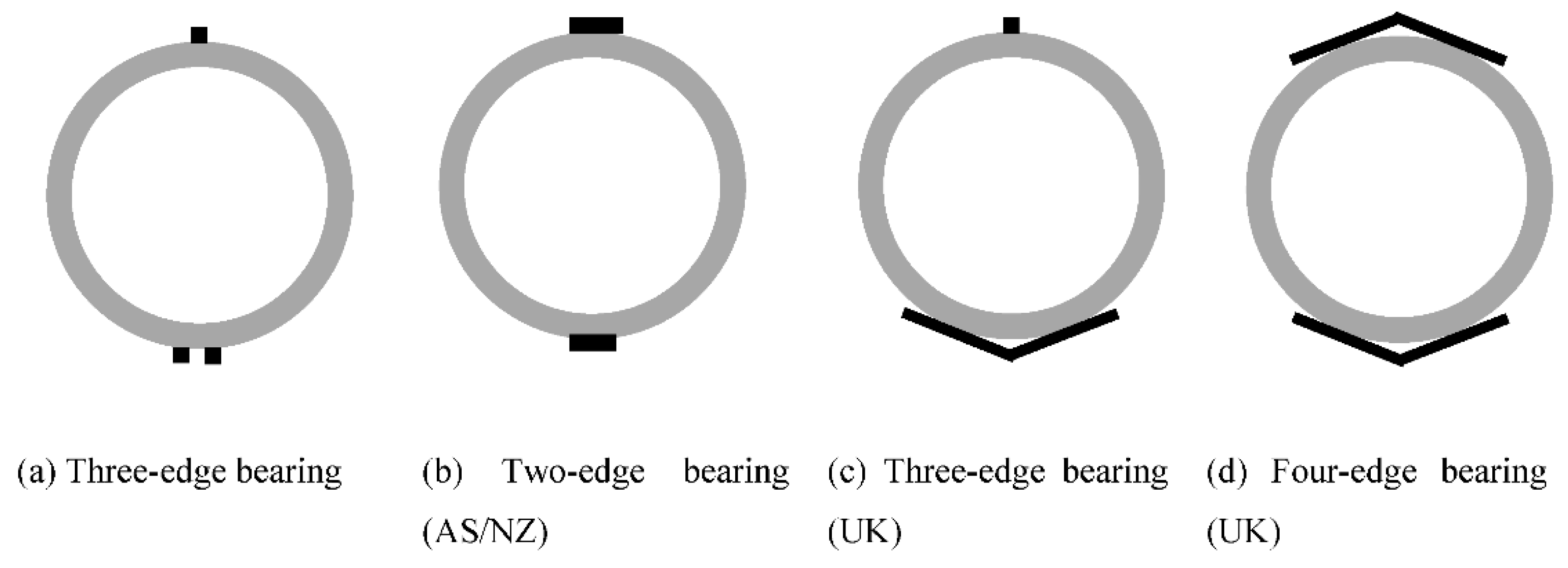
| Load test | Test to determine strength of the pipe in Newtons, also known as the three-edge bearing test or crushing test. In some areas, the load is based on two edges or four edges. Regardless, the edge load is applied to the crown and the invert of the pipe parallel to the axis of the pipe. |
| Min. crushing load | See Design crack load. |
| Pipe (strength) class | The direct translation of the crack load. In some areas, such as Canada, the value of the crack load is normalized. The pipe class is measured in Newtons per meter of pipe per millimeter of inner diameter. In some other areas, the class is presented in category, e.g., in the US: Class I, II, III, IV and V. |
| Proof load | See Design crack load |
| RCP | Reinforced concrete pipe, also called “the pipe” in this document. |
| SFRCP | Steel fiber-reinforced concrete pipe |
| Spigot | Male end of the pipe, also named tongue. |
| SynRCP | Synthetic fiber-reinforced concrete pipe |
| Test crack load | The actual testing load that the crack reaches the crack limit. The value is recorded during the test. If the test crack load is greater than the design crack load, the pipe passed the crack load requirement. This load is also known as three-edge bearing load or D-load in Canada and US. |
| Test ultimate load | The maximum load recorded in the load test of the pipe before losing the strength. If the test ultimate load is greater than the ultimate load, the pipe passed the ultimate load requirement. This is also known as collapsed load in UK. |
| Three-edge bearing load | Three-edge bearing load: see Test Crack Load; Three-edge bearing test: See Load Test |
| Ultimate load | The maximum sustained load that the pipe can withstand. |
| Size | Inner Diameter Tolerance | Wall Thickness Tolerance | ||||||
|---|---|---|---|---|---|---|---|---|
| Canada | US | AS/NZ | China | Canada | US | AS/NZ | China | |
| 300 | ±5 | ±6 | ±7 | +4/−8 | −3/+ | ±3 | −3/+5 | −2/+8 |
| 450 | ±7 | ±8 | ±7 | +4/−8 | −3/+ | ±3 | −4/+5 | −2/+8 |
| 600 | ±9 | ±9 | ±7 | +4/−8 | −4/+ | ±4 | ±5 | −2/+8 |
| 675 | ±7 | ±7 | ±8 | +4/−8 | −4/+ | ±4 | ±6 | −2/+8 |
| 900 | ±9 | ±9 | ±8 | +6/−10 | −5/+ | ±5 | ±7 | −3/+10 |
| 1200 | ±10 | ±9 | ±8 | +6/−10 | −5/+ | ±5 | ±8 | −3/+10 |
| 1500 | ±10 | ±9 | ±10 | +6/−10 | −5/+ | ±5 | ±9 | −3/+10 |
| 1800 | ±10 | ±9 | ±13 | +8/−12 | −5/+ | ±5 | ±10 | −4/+12 |
| 2400 | ±10 | ±9 | ±13 | +8/−12 | −5/+ | ±5 | ±10 | −4/+12 |
| 3000 | ±10 | ±9 | ±13 | +10/−14 | −5/+ | ±5 | ±10 | −5/+14 |
| Size | CAN/US | AS/NZ | China |
|---|---|---|---|
| 300 | 6 | 2 | 10 |
| 450 | 6 | 2 | 10 |
| 600 | 6 | 3 | 10 |
| 675 | 7 | 3 | 10 |
| 900 | 9 | 5 | 10 |
| 1200 | 12 | 6 | 12 |
| 1500 | 15 | 8 | 15 |
| 1800 | 16 | 9 | 15 |
| 2400 | 20 | 10 | 15 |
| 3000 | 20 | 10 | 15 |
| Study Areas | Class 1 | Class 2 | Class 3 | Class 4 | Class 5 |
|---|---|---|---|---|---|
| Canada | -- | 50D: 30 MPa ≤ 2400 mm 35MPa > 2400 mm | 65D: 30 MPa ≤ 2100 mm 35 MPa > 2100 mm | 100D: 30 MPa ≤ 1350 mm 35 MPa > 1350 mm | 140D: 40 MPa all size |
| US | CL1: 28 MPa ≤ 2400 mm 34 MPa > 2400 mm | CL2: 28 MPa ≤ 2400 mm 34 MPa > 2400 mm | CL3: 28 MPa ≤ 2100 mm 34 MPa > 2100 mm | CL4: 28 MPa ≤ 1350 mm (B-wall) or 35 MPa larger dia. 1650 mm (C-wall) | CL5: 42 MPa all size |
| UK | 40 MPa all sizes and classes | ||||
| Australia & New Zealand | Not specified in the materials standard | ||||
| China | 40 MPa all size and class | ||||
| Study Area | Condition | Permissible Limit | Mating Surface |
|---|---|---|---|
| Canada/US | Single cage | Place at 35–50% from inner wall, min 13 mm | Spigot 6.5 mm to the circumf. Wire |
| Bell 13 mm to the circumf. wire | |||
| Double/multiple cages: | |||
| Wall < 63 mm Wall ≥ 63 mm | 19 mm, min 13 mm 25 mm, min 13 mm | No restriction to the longitudinal wire | |
| UK | General condition | 15 mm or max aggregate size whichever is larger * | Not specified |
| Australia/New Zealand | Dry Cast Wall ≤ 25 mm 25 mm < wall ≤ 35 mm Wall > 35 mm Wet Cast (50 MPa) | Barrel ** 6/- mm 8/- mm 10/20 mm 25/35 mm | Mating surface ** 4/- mm 5/- mm 6/10 mm 25/35 mm |
| China | Wall ≤ 40 mm 40 mm < Wall ≤ 100 mm Wall > 100 mm | Min 10 mm cover Min 15 mm cover Min 20 mm cover | Not specified |
| Procedure and Setup | Canada | US | UK | Australia/New Zealand | China |
|---|---|---|---|---|---|
| Load orientation (Figure 9) | Three edges | Three edges | Three edges Four edges | Two edges Three edges | Three edges |
| Load rate (kN/min/m) | 7–37 | Max 109.4/43.8 Max 43.8 | 20–25 | Min 10 | 30 |
| Load incrementation to crack load | Continuous to design and actual crack load | Continuous to design and actual crack load | Load to design crack load and hold for crack inspection | Load to design crack load and hold for crack inspection remove the load and re-inspect the crack. | Load to 80% DL Step load until crack load is determined Hold load at each interval |
| Load incrementation to ultimate load | Continuous from crack load to ultimate (collapse) load if needed | Continuous from crack load to ultimate (collapse) load if needed | Continuous to ultimate (collapse) load | Continuous to design ultimate load | Load 80% UL Increase at an interval until collapsed. Hold load for inspection |
| Crack limit under crack load | 0.3 mm wide × 300 mm long | 0.3 mm wide × 300 mm long | 0.3 mm wide × 300 mm long | 0.15–0.25 mm ** × 300 mm long | 0.2 mm × 300 mm long |
| Allowable crack width (w/o load) | Not specified | Not specified | 0.15 mm × 300 mm long | 0.1–0.2 mm *** × 300 mm long | 0.05 mm |
| Measuring tool | Crack gauge | Crack gauge | Not specified | Crack gauge | Crack gauge |
| Crack load determination | Actual crack load | Actual crack load | Design crack load (Pass/Fail) | Design crack load (Pass/Fail) | Actual crack load |
| Ultimate load determination | Actual ultimate load | Actual ultimate load | Actual ultimate load | Design ultimate load (Pass/Fail) | Actual ultimate load |
| Concrete Cover | Pipe Loaded | Load Removed |
|---|---|---|
| ≤10 mm | 0.15 mm | 0.10 mm |
| Between 10 mm and 20 mm | 0.20 mm | 0.15 mm |
| ≥20 mm | 0.25 mm | 0.20 mm |
| Study Area | # of Test Pipes | Test Ori. | Straight Alignment | Deflection | Differential (Shear) Load | Joint Shear Test | Other Requirements |
|---|---|---|---|---|---|---|---|
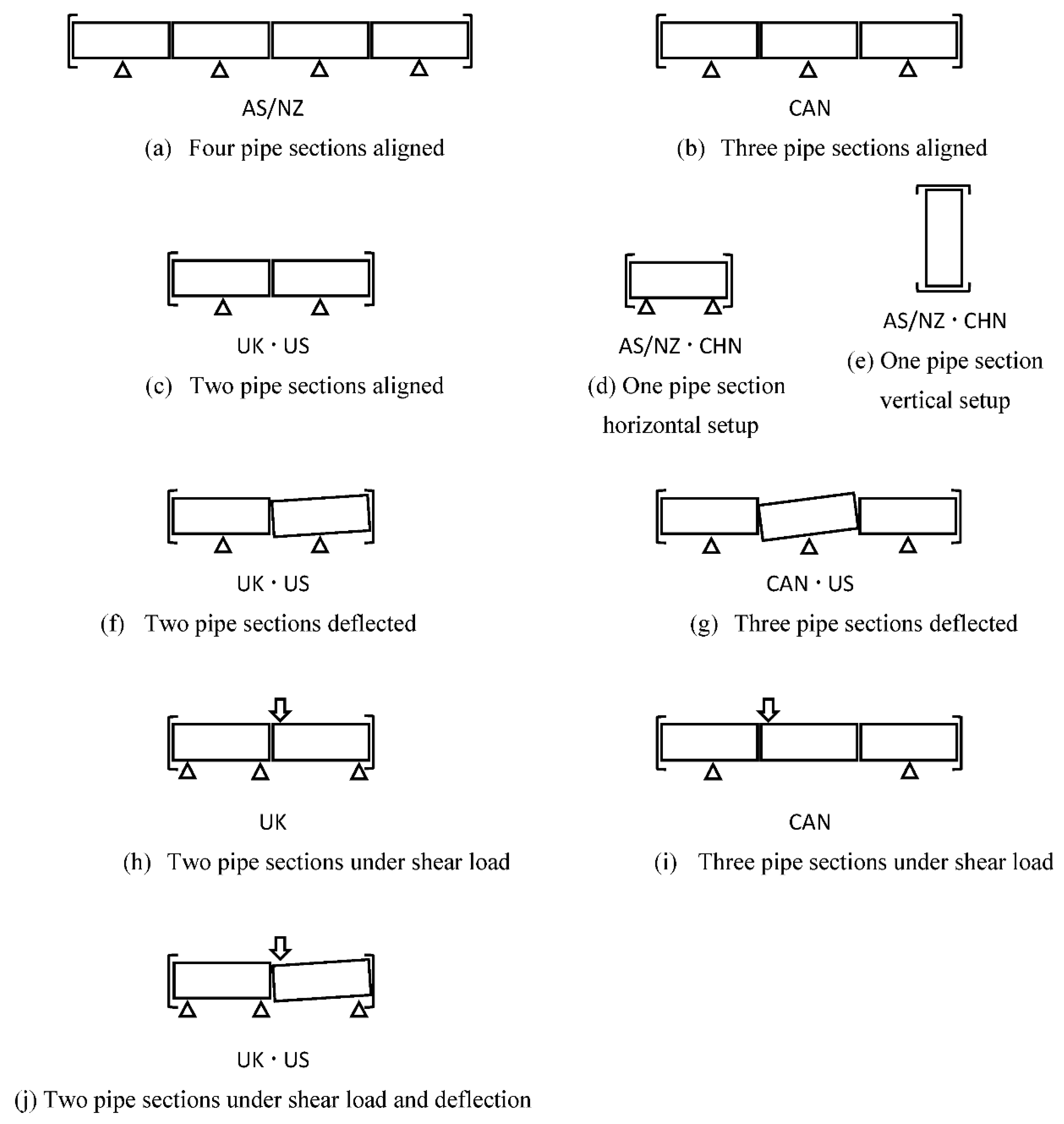
| Canada | 3 | Horizontal | 103 kPa (10 min) | 90 kPa (10 min) | 35 kPa at 10 min 45 kN shear load | Shear load during hydro | Owner’s requirement Not required if size larger than 1200 mm |
| US | 2 | Horizontal or Vertical | 90 kPa (10 min) | 69 kPa (10 min) | Not required | Shear load without hydro | Owner’s requirement |
| UK | 2 | Horizontal | 50 kPa (15 min) | 50 kPa (15 min) | 50 kPa for 15 min | 50 kPa for 15 min | Not required if wall is thicker than 125 mm |
| China | 1 | Horizontal or Vertical | 60 kPa CL1 (10 min) 100 kPa CL2 & 3 (10 min) | Not specified | Not specified | -- | Not required if wall is thicker than 150 mm |
| Australia/New Zealand | 1 | Horizontal or Vertical | 90 kPa (90 s/10 mm wall thickness) | Not specified | Not specified | -- | -- |
| Australia/New Zealand | 4 | Horizontal | 90 kPa ≤ 0.6 mL/mm/m loss rate in 1 h | Not specified | Not specified | -- | -- |
| Australia/New Zealand | 4 | Horizontal | Pspec = pressure rating Ptest = 1.2 Pspec Pult = 1.5 Pspec for 30 s | Not specified | Not specified | Yes | Contract requirement |
| Study Area | Limit | Dry Sample | Wet Sample Immerse Temperature | Wet Sample Immerse Duration |
|---|---|---|---|---|
| US | 9% | Mass Diff < 0.1% in 6 h | 105–115 °C | 5 hr |
| Canada | 9% | Mass Diff < 0.1% in 6 h | 105–115 °C | 5 hr |
| UK | 6% | Mass Diff < 0.1% in 24 h | 20 ± 3 °C | Mass diff < 0.1% in 24 h |
| Australia/New Zealand | 6% | Mass Diff < 0.1% or <0.5 g in 4 h | 100 °C | 5 h |
| China | Not specified | Not specified | Not specified | Not specified |
| Minimum Concrete Cover (mm) | Canada/US | Australia/New Zealand | China | UK |
|---|---|---|---|---|
| 6 | -- | Wall ≤ 25 mm, normal exposure, dry cast | -- | -- |
| 8 | -- | 25 mm < Wall ≤ 35 mm, normal exposure, dry cast | -- | -- |
| 10 | -- | Wall > 35 mm, normal exposure, dry cast | Wall ≤ 40 mm | -- |
| 13 | All wall thickness | -- | -- | -- |
| 15 | -- | -- | 40 mm < Wall ≤ 100 mm | All wall thickness (not defined as minimum) |
| 20 | -- | -- | Wall > 100 mm | -- |
| 25 | -- | Wall > 35 mm, aggressive exposure, dry cast | -- | -- |
| 35 | -- | Wall > 35 mm, aggressive exposure, wet cast | -- | -- |
© 2018 by the authors. Licensee MDPI, Basel, Switzerland. This article is an open access article distributed under the terms and conditions of the Creative Commons Attribution (CC BY) license (http://creativecommons.org/licenses/by/4.0/).
Share and Cite
Wong, L.S.; Nehdi, M.L. Critical Analysis of International Precast Concrete Pipe Standards. Infrastructures 2018, 3, 18. https://doi.org/10.3390/infrastructures3030018
Wong LS, Nehdi ML. Critical Analysis of International Precast Concrete Pipe Standards. Infrastructures. 2018; 3(3):18. https://doi.org/10.3390/infrastructures3030018
Chicago/Turabian StyleWong, Lui S., and Moncef L. Nehdi. 2018. "Critical Analysis of International Precast Concrete Pipe Standards" Infrastructures 3, no. 3: 18. https://doi.org/10.3390/infrastructures3030018
APA StyleWong, L. S., & Nehdi, M. L. (2018). Critical Analysis of International Precast Concrete Pipe Standards. Infrastructures, 3(3), 18. https://doi.org/10.3390/infrastructures3030018


