1. Introduction
With the fast-growing wind energy industry, the requirement for a reliable wind turbine tower is critical in terms of the structural safety and power production. Since the wind resource is more stable (i.e., less wind turbulence) and more sustainable (i.e., more convertible wind resource) in high altitude (generally speaking, higher than 100 ), the wind turbines are growing taller to extract more energy. However, just like all the other technologies in this world, there is always a trade-off—the quest for higher and larger turbines comes with its fair share of engineering challenges.
To give an illustration, taller wind turbine towers suffer from highly intensive loads induced directly by the airflow and indirectly from the nacelle and the blades. The vibrations and ultimate loads transferred to the tower reduce its service life and involve many other problems such as cracks due to the fatigue damage. To overcome this mechanical engineering challenge, the two foremost used approaches are modified controller methods and damper based methods. The former is mainly based on Pitch Angle Control (PAC) that controls the blades’ pitch angle to counterbalance the vibrations on the wind turbine tower [
1,
2,
3]. Due to the limited rotation speed of the pitch angle, this method usually has a slow response. However, it enhances the vibration control with minimum extra cost since there is no need for additional equipment. On the contrary, the damper-based methods are more effective in reducing vibrations as they embed a specifically designed damping system inside the wind turbine. Absorber systems are widely used in civil engineering structures to reduce vibration responses [
4,
5,
6]. However, some of these methods are of significant cost.
The embedded damping system can be mainly categorized into three types: passive, semi-active, and active. One of the famous damping systems is Tuned Mass Damper (TMD), which is employed in different structures such as bridges and tall buildings [
7], footbridges [
8] and submerged floating tunnel [
9]. As for wind turbine structures, Si et al. [
10] have applied TMD on spar platforms for offshore wind turbines. It showed that the performance of TMD depends mainly on its mechanical properties, namely the spring coefficient and the damping ratio. The TMD with a large spring and damping ratio offered a considerable load reduction when the turbine is working below rated or in low-frequency resonant motion. In contrast, the TMD with a small spring coefficient contributed much to load reduction when the turbine is working above the rated condition. Tong et al. [
11] proposed to use a bidirectional tuned liquid column damper (BTLCD) to reduce the tower loads. The numerical simulations revealed that BTLCD can reduce loads by up to 27%. Stewart and Lackner [
12] have proposed a set of optimum TMDs by creating a limited degree-of-freedom model for both onshore wind turbines and offshore ones with a barge, monopile, spar buoy, or tension-leg platform. A load reduction by up to 20% is achieved for the various TMD configurations. Despite all these achievements, the passive dampers have some downsides when applied to wind turbines. Firstly, based on its principle, passive dampers need to be massive in order to deliver an effective damping force. This explains why the passive dampers nowadays are mainly implemented on the supporting platform of offshore wind turbines [
13,
14,
15,
16]. Secondly, the passive dampers are tuned to a single frequency. Consequently, they are only effective over a narrow-band of frequencies. It is hard to tune the passive dampers to reduce vibrations for rotor frequency (1P) and blade passing frequency (3P).
To overcome such issues, an active damper is an effective solution. Fitzgerald and Basu [
17] combined a TMD with a control algorithm through a cable to reduce in-plane vibrations for wind turbine blades. Coudurier et al. [
18] proposed a control strategy to improve the effectiveness of tuned liquid column dampers (TLCD) for offshore wind turbines. Some recent researches [
19,
20,
21,
22] proposed to reduce the vibrations on wind turbine towers by operating the pitch angles of the blades. Since the power production of wind turbines relies on the wind source captured by the blades, using the pitch control to damp the wind tower vibrations may lead to a loss in the power production. Therefore, Gambier [
23] has investigated such a problem by using multi-objective optimization in order to seek an optimal balance between the pitch control and the active tower damping control. Active dampers have significant advantages over passive dampers in damping a broader band of frequencies and more control availabilities [
24]. However, an external power supply is mandatory, which limits the application of those active dampers. Moreover, the complexity of the active damper’s structure and control system also leads to reducing their maintainability and reliability.
Recently, Scheller [
25] proposed a new active damper named the twin rotor damper (TRD) for damping structural vibrations. Unlike other active dampers, TRD generates the damping force from rotating control masses instead of accelerating and decelerating control masses [
26]. This makes TRD more power-efficient and opens the possibility of implementing an active damper in limited space such as the inner space of a wind turbine tower. To the best of our knowledge, an active damping system inside the wind turbine tower with such a device has not been discussed yet. In addition, most current research focuses on turbulent wind conditions [
10,
11,
12,
17,
21,
27]. In this paper, we study the feasibility of using the TRD for vibration control of wind turbine towers. A theoretical prototype of the damping system (i.e., the damper and the associated control algorithm) is proposed for a baseline wind turbine. An idealistic wind gust is involved to evaluate the effectiveness of the proposed system in reducing peak-to-peak amplitude.
The main contributions of this paper include:
A grid search on the timing of an internal or external electrical system fault combined to gusty wind conditions with respect to IEC61400 standards;
Theoretical design of an active damping system including the TRD and a control algorithm to reduce the vibrations of wind turbine towers;
Evaluation of the proposed damping system in an extreme load event triggered by the loss of electrical network connection while the turbine is producing power;
Investigations and discussions on the use of TRD for damping wind turbine vibrations; a comparison between TRD and other types of damping system used in the wind industry.
The rest of the paper is organized as follows: a brief presentation of the TRD is given in
Section 2; the design of an active damping system using the TRD is presented in
Section 3; numerical simulations are used to demonstrate the efficiency of the proposed damping system in
Section 4; conclusions and outlooks are presented in
Section 5.
3. Design of a Damping System with the TRD for Wind Turbine
A wind turbine is a complex structure coupling solid–fluid interactions as well as electromechanics. It is impossible to evaluate the performance of wind turbines under every realistic condition during their lifetime. In the typical design process nowadays, a wind turbine is designed for a set of operating conditions in such a way that, if the environment meets that condition, in reality, the wind turbine should achieve at least the desired performance. A commonly used industrial standard is IEC61400-1 [
36], which characterized not only a set of wind conditions but also a variety of incidents and special states.
The TRD will be applied to an aero-hydro-servo-elastic model of wind turbine using FAST. In order to stay as close as possible to the previous context of the SDOF oscillator, we set a Design Load Case (DLC) with a longitudinal wind speed and no other exciting force. A commonly used DLC involving such wind conditions is the Extreme Operating Gust (EOG) [
36], in which the wind speed shortly increases to a high level and deflects the whole turbine. This DLC will be combined with a grid-loss event, which consists of quickly stopping the wind turbine operation and adding extra excitations to the wind turbine. Then, the turbine oscillates periodically around its rest position at the wind turbine’s natural frequency.
3.1. NREL 5MW Reference Wind Turbine with FAST Simulation Tools
Many numerical modeling tools have been developed to simulate the dynamics of a wind turbine [
37,
38,
39]. An open source software, FAST [
40], is used in this work. It allows an aero-hydro-servo-elastic coupled simulation considering all the wind turbine components.
FAST simulates the entire wind turbine as a combination of flexible and rigid bodies. Firstly, the wind condition (i.e., a time series of wind speed in the spatial domain) is generated by using its wind speed model based on its definition given in
Section 3.2. The dynamic analysis is then carried out by evaluating its aerodynamic model, elastic structure model, functional model, and the other supplementary models. Finally, the resulting deflections, forces, and moments computed on the tower and blades are exported and can be analyzed.
Two reference wind turbines are commonly used in the field of numerical simulations: (1) NREL offshore 5 MW baseline wind turbine [
41]; (2) DTU 10-MW reference wind turbine [
42]. Both are initially designed for offshore scenarios. However, an onshore NREL 5 MW reference wind turbine is also part of FAST certification tests, allowing us to validate our model integration into the software. Despite that, there is no real-world implementation or application of the NREL 5 MW turbine, it is still a meaningful reference wind turbine that has been widely studied in academic research and is often used as a benchmark in developing or investigating wind turbine technologies [
43,
44,
45,
46,
47]. For this reason, this baseline wind turbine is modeled in FAST and served as an initial design for an onshore wind turbine in this work.
The key characteristics of the NREL 5 MW reference wind turbine are mainly based on the specification of the REpower 5M wind turbine and the Dutch Offshore Wind Energy Converter Project (DOWEC) [
48]. It is a three-bladed horizontal-axis wind turbine (HAWT) with the key properties given in
Appendix A Table A1.
3.2. Design Load Case
3.2.1. Wind Condition: Extreme Operating Gust (EOG)
The most essential parameter for characterizing the wind condition is the mean wind speed. It is the mean value of wind speeds measured at hub height over a period of 10 min for several years. The annual mean wind speed at hub height is imperative for identifying normal conditions as well as extreme conditions.
The wind speed distribution is described by a probability distribution function at hub height. For the normal wind conditions, it is assumed to follow a Rayleigh distribution, that is to say, a Weibull distribution with a shape factor of 2. Equation (
34) provides the cumulative probability function for this condition.
where,
| = wind speed at hub height (). |
| based on the wind turbine class specified by designer () |
The wind speed distribution determines the occurrence of individual load condition over wind turbine.
To determine the wind profile (aka vertical wind shear), the Hellmann power-law model is applied with an exponent of
. It describes the mean wind speed as a function of height
z above the ground:
where,
| z | = height above ground level () |
| = wind turbine hub height (). |
In order to study the ultimate loads on wind turbines, an extreme wind condition must be designated. The Extreme Operating Gust (EOG) model is involved in the present work. It introduces a Mexican-hat change in wind speed while keeps the same wind direction. This makes it a good choice for investigating the structural responses of the wind turbine tower under ultimate loads.
To be specific, a wind gust is a rapid change in the wind speed. It needs to be characterized by its rise-time, its magnitude and its duration. An EOG is a gust appearing in a short period of time
when the turbine is operating at the same time. By definition, the EOG concerns only the wind velocity in the longitudinal direction (i.e., wind direction). The horizontal and vertical wind velocities are equal to 0. The magnitude of EOG at hub height
depends on the turbulence standard deviation
, the scale of the turbulence
, and the rotor diameter of the turbine
D.
where,
| = annual extreme wind speed () |
| = wind speed at hub height () |
| = standard deviation of wind speed |
| D | = diameter of the rotor () |
| = longitudinal turbulence scale parameter (). |
According to the IEC 61400-1 standard [
36], the longitudinal turbulence scale parameter
at hub height
z is defined as:
The wind speed of gust is, therefore, given by its magnitude
and its duration
:
The duration of gust
is set to
by the standard [
36]. More information about the probability of occurrence, the period and the spatial distribution of the gust can be found in [
49].
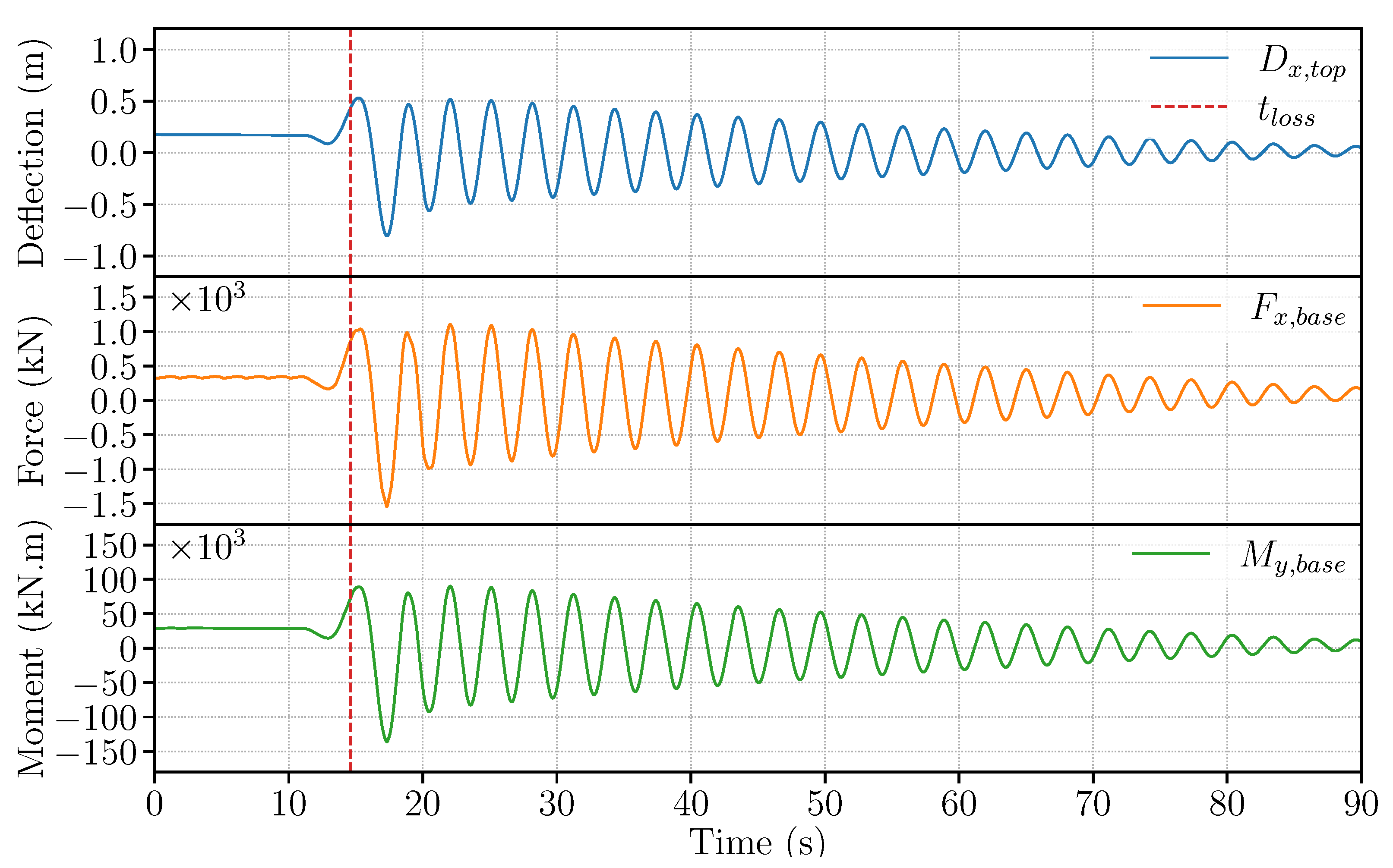
3.2.2. Operating Condition: Grid Loss
In the above section, the magnitude of wind gust
and the wind speed of gust
have been given in Equations (
36) and (
38), respectively. The duration of gust
is fixed at
by IEC 61400-1 specifications [
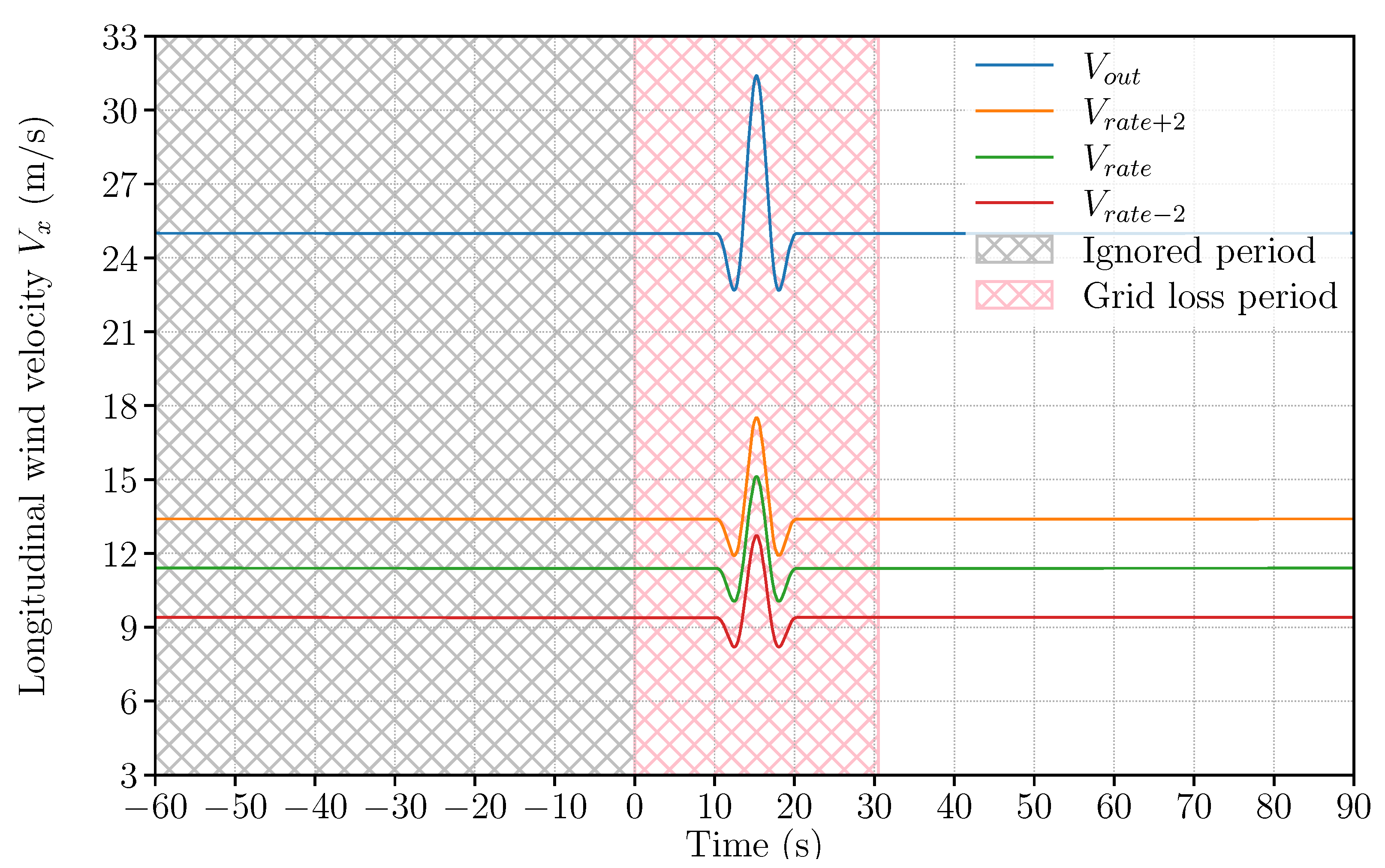
36]. We added a period of 60
before the wind gust event to avoid the noise in dynamic response. Another 100
is also added after the wind gust event to track decaying vibration. An illustration of this wind condition is plotted in
Figure 4.
The red hatched region in
Figure 4 represents the eventual coincidence between the EOG and an electrical fault (i.e., grid loss). The grid loss is an incident that assumes that the connection to the power network is broken due to an internal or external reason. The electrical generator should be shut down immediately by the protection system. Otherwise, the subsequent loading may lead to a resonance between the natural frequency of the tower and that of the rotating blades.
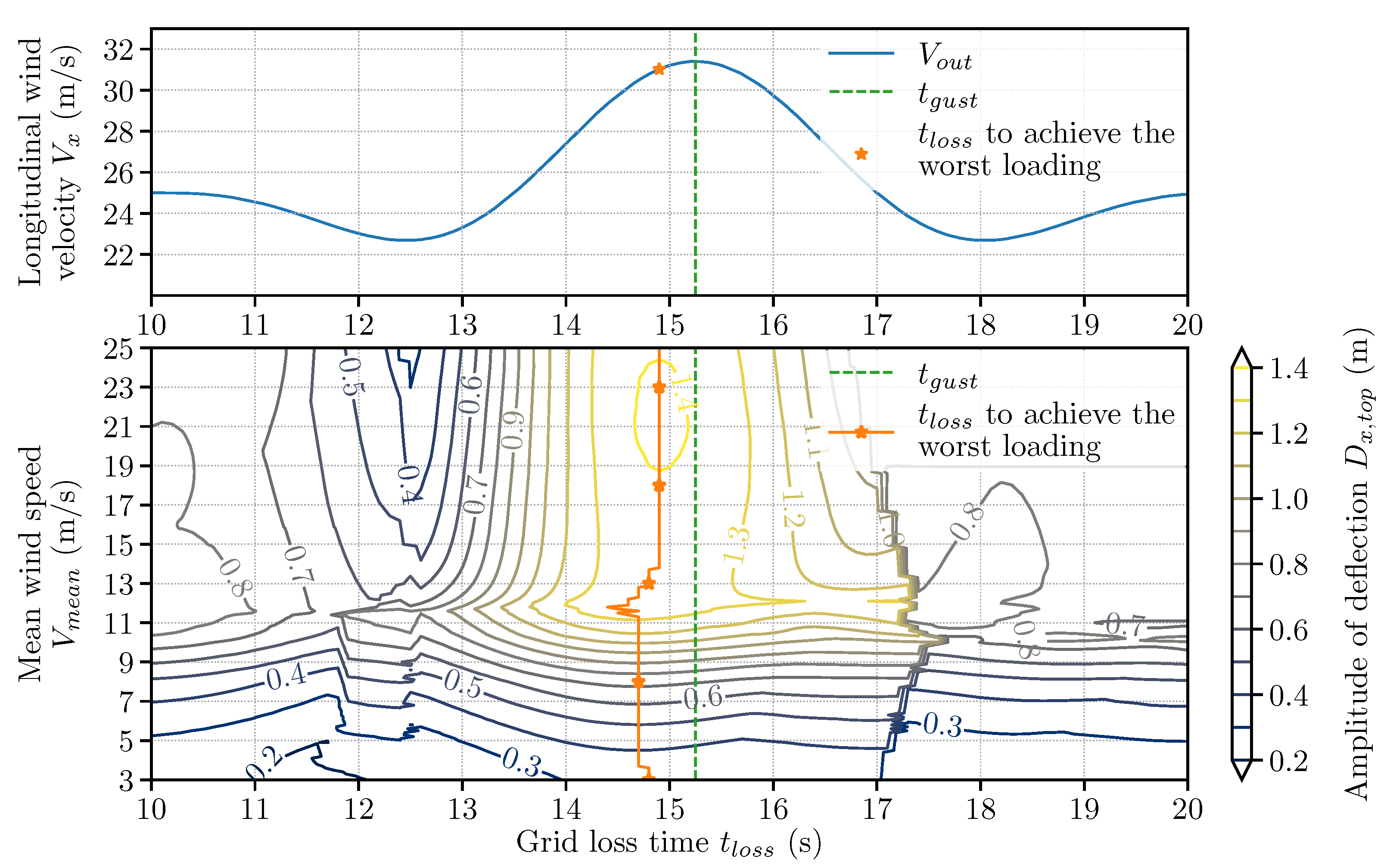
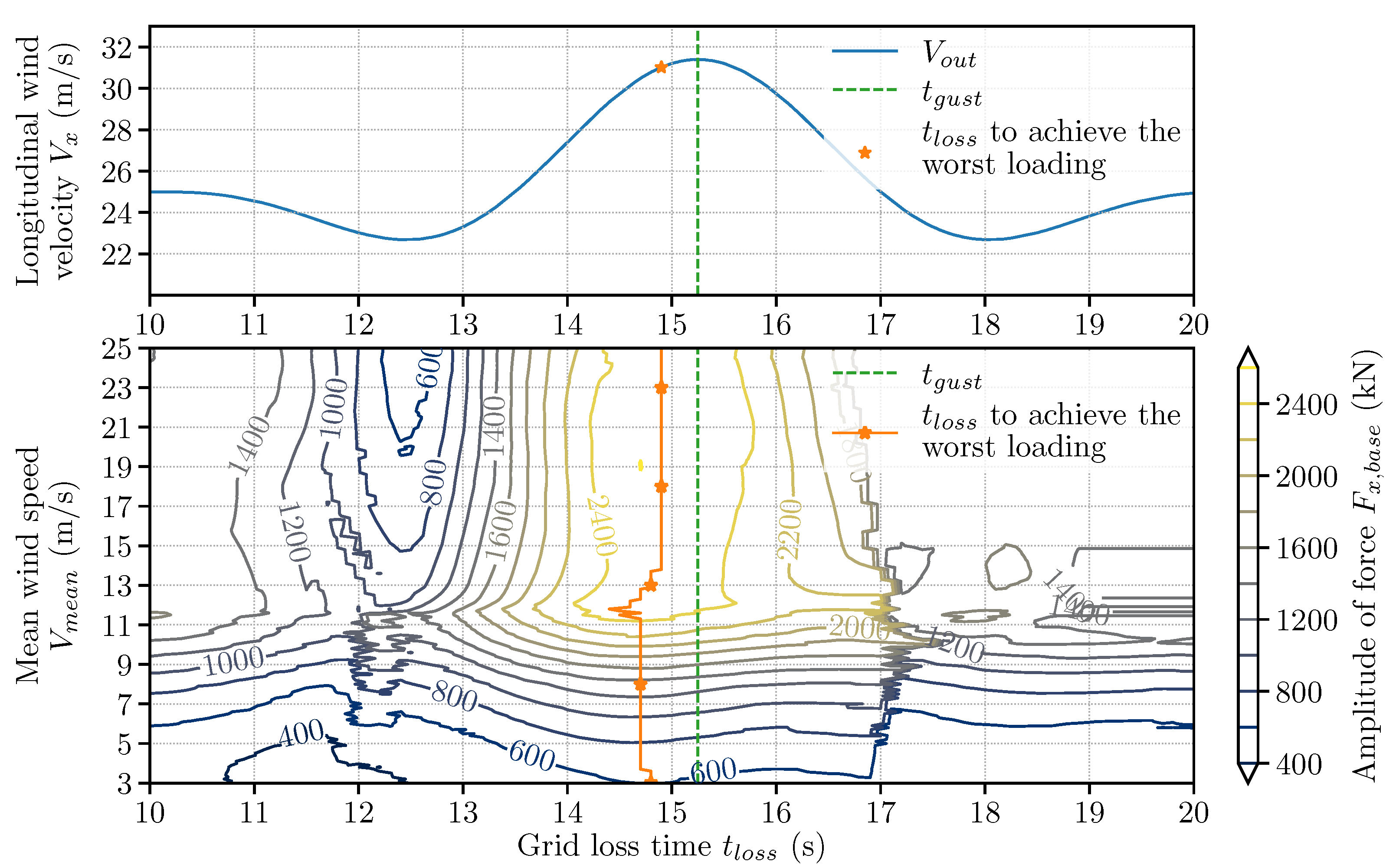
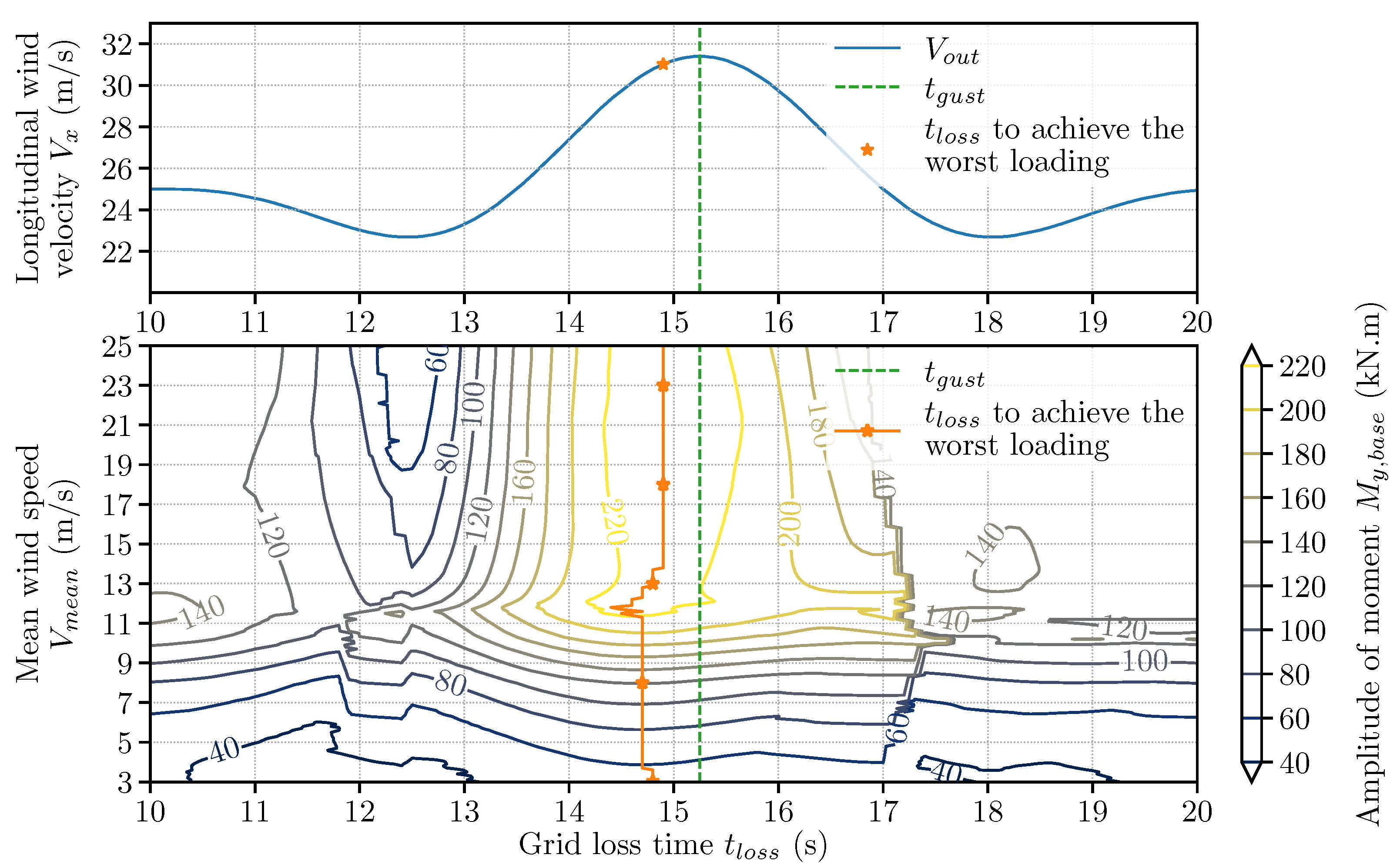
Here, the term “immediately” is numerically selected by the user. In this work, a period of
is set to represent the reaction time of the wind turbine protection system. To achieve the worst loading on wind turbine, the timing of grid loss was tested between 0
and
(i.e., the red hatched zone in
Figure 4) with a time-step of
. The numerical results will be shown and discussed in
Section 4.1.
3.3. Numerical Setup of FAST with TRD
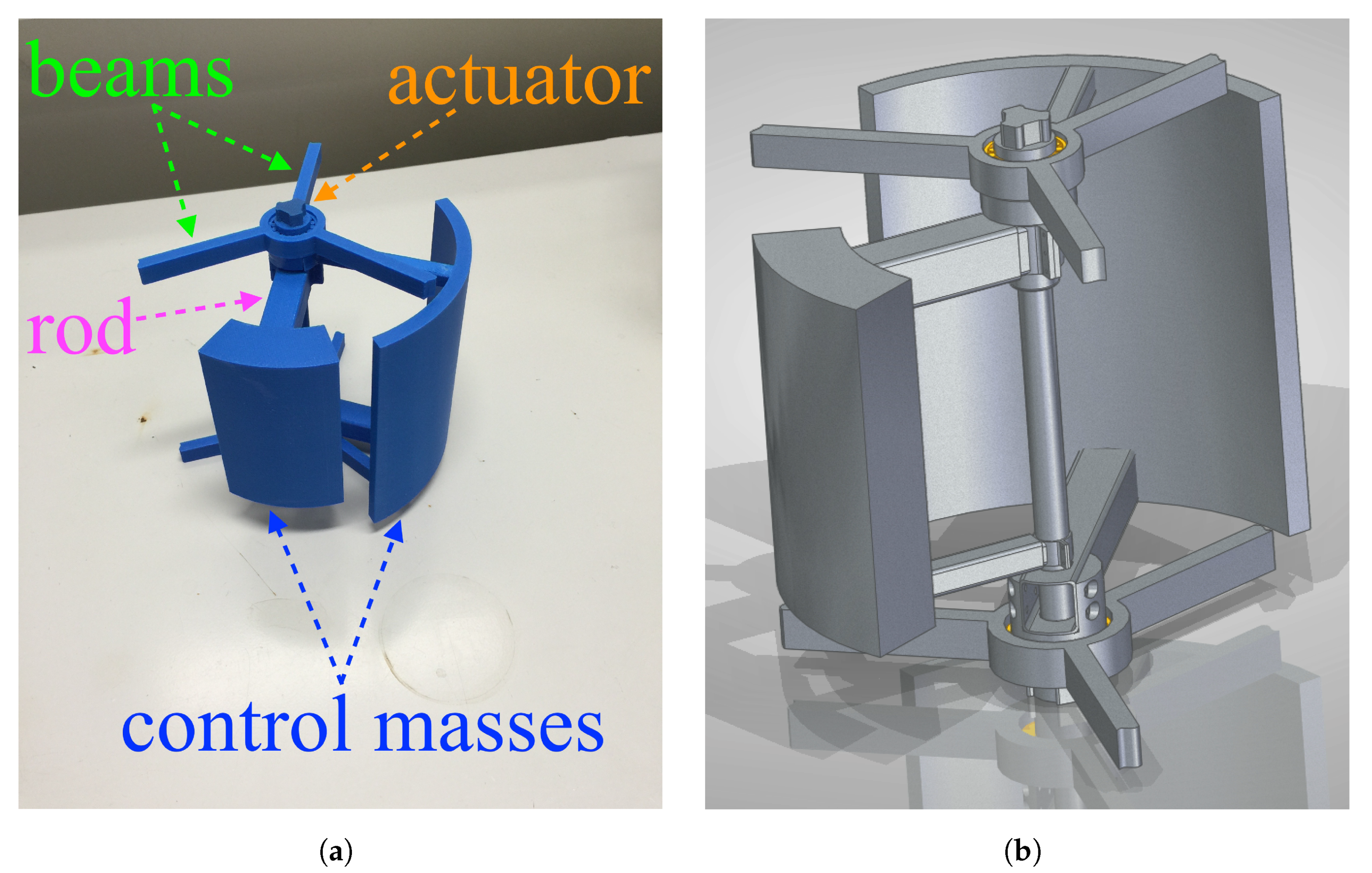
A potential engineering design of TRD for a wind turbine is illustrated in
Figure 5. Due to the lack of space inside the wind turbine, the TRD is planned to be installed inside the wind turbine tower. The TRD unit could be attached to the inner surface of the tower by six steel beams; more clearly, three beams on the top and three beams on the bottom. This would ensure a rigid connection between the TRD unit and the structure of the wind tower. The actuator would be placed along the centerline of the tower and connected to the beams through an upper bearing and a lower bearing. Then, the two control masses will be hinged to their actuator by rods. Each control mass would likewise be connected to the actuator axis by two rods, that is, an upper one and a lower one.
When a vibration needs to be damped, the control algorithm of TRD (see
Section 2.3.3) will send a signal to the TRD’s actuator to move the rods. Using an electromagnetic coil (or motor-based actuator), the actuator rotates the actuator axis, moving the connecting rods, and consequently rotating the attached control masses. The control masses are made by the same material and have the same mass. However, their layouts and radius (the length of rods) are made to be different so that they can be installed on the different rings (see
Figure 5). The product of control mass and radius
for the rotor on the inner ring is kept the same as that on the outer ring.
The TRD is tuned to reduce the vibration under the most important mode, that is, the natural mode which causes the largest loads on the full-system. Several previous studies [
12,
50] have identified that the 1st tower fore-aft bending mode is the most important. In this work (see
Table A1), it has a natural frequency of
for this work.
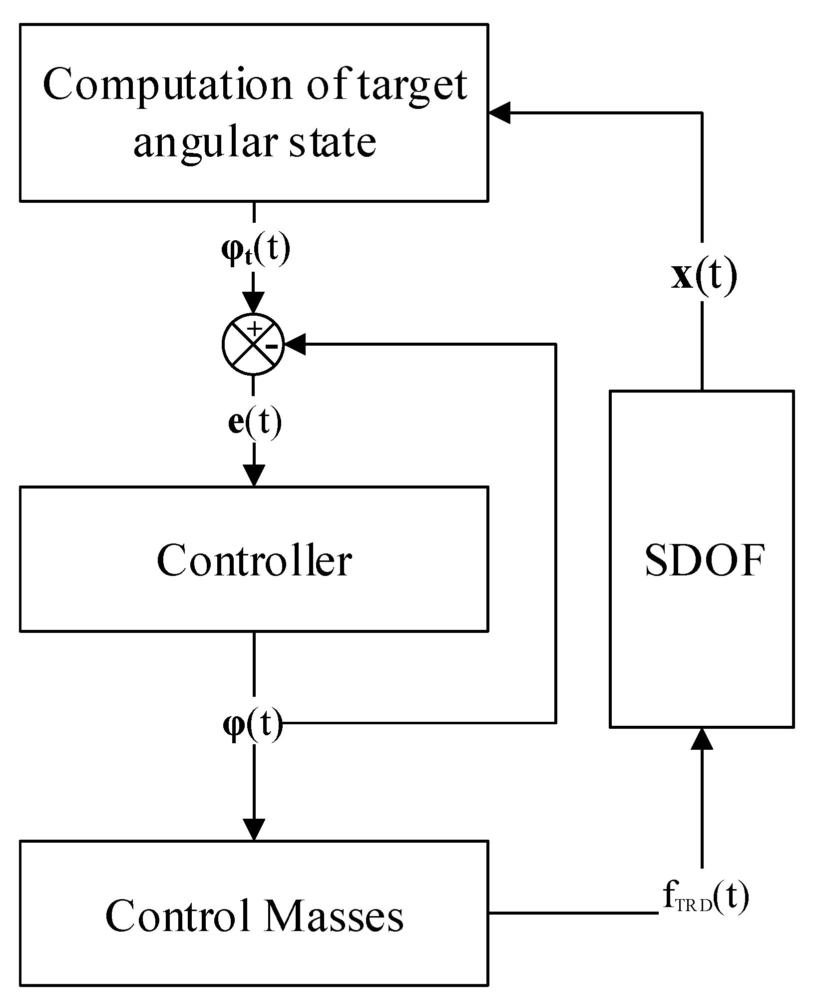
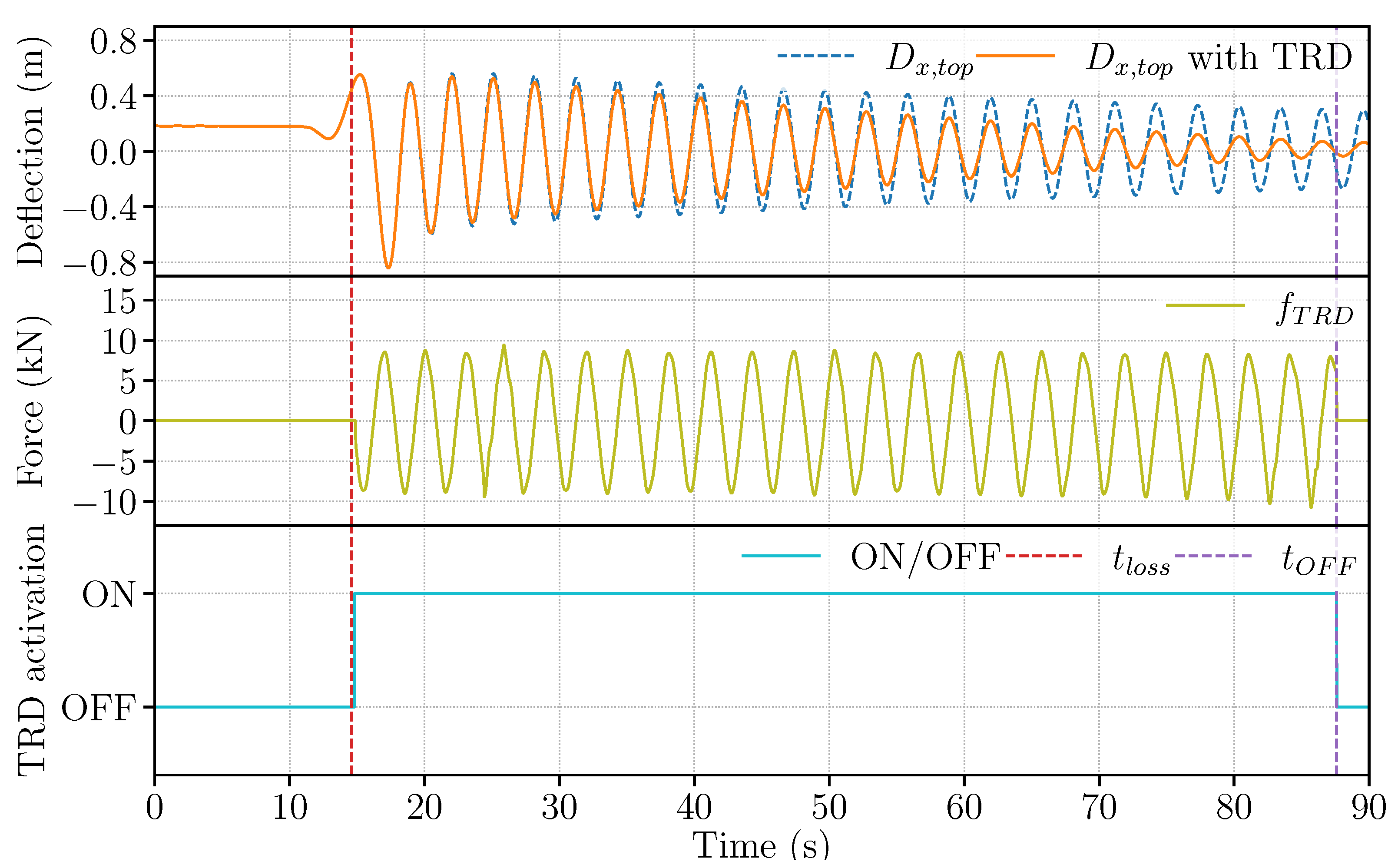
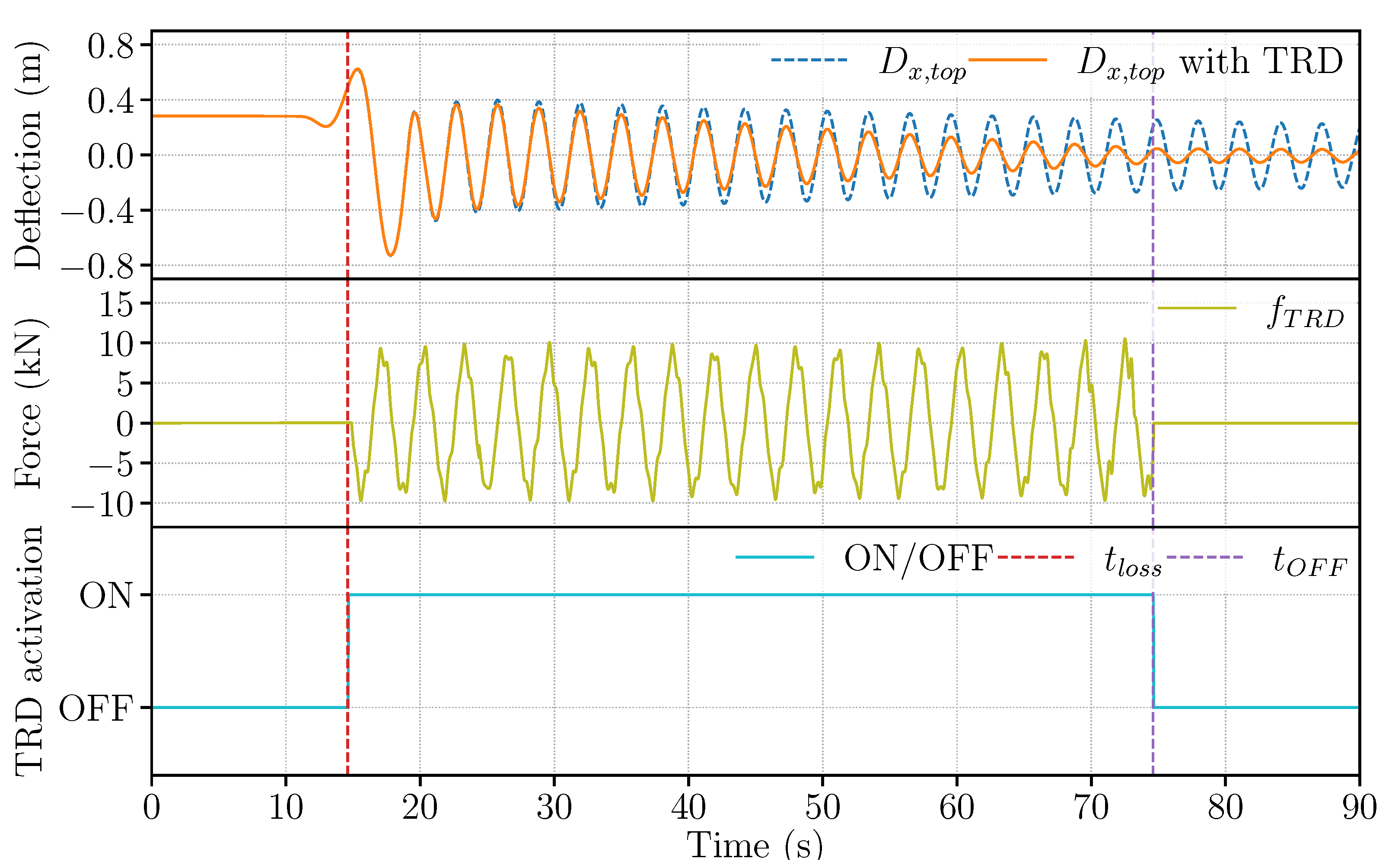
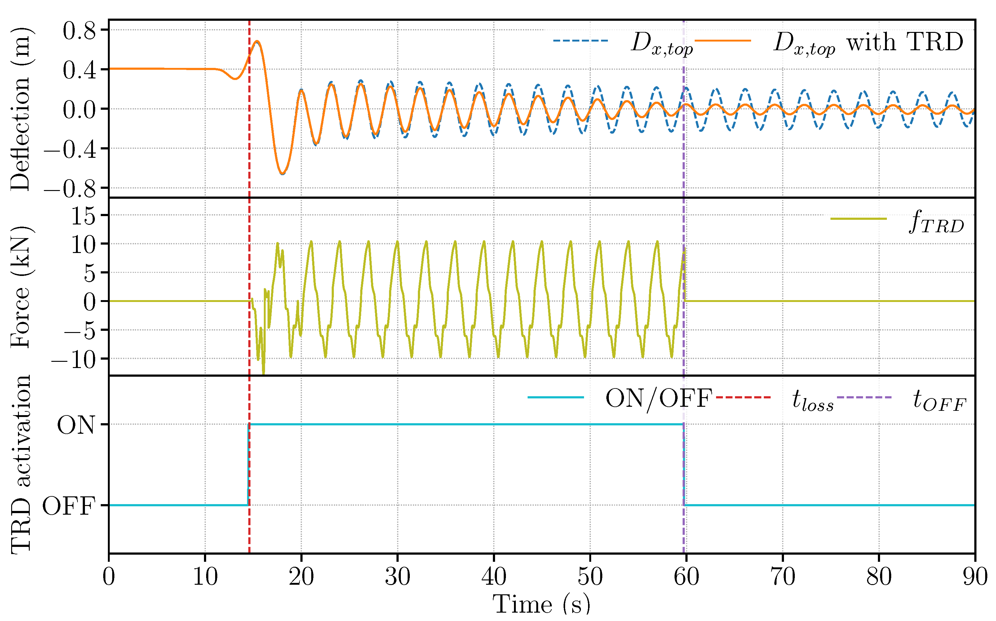
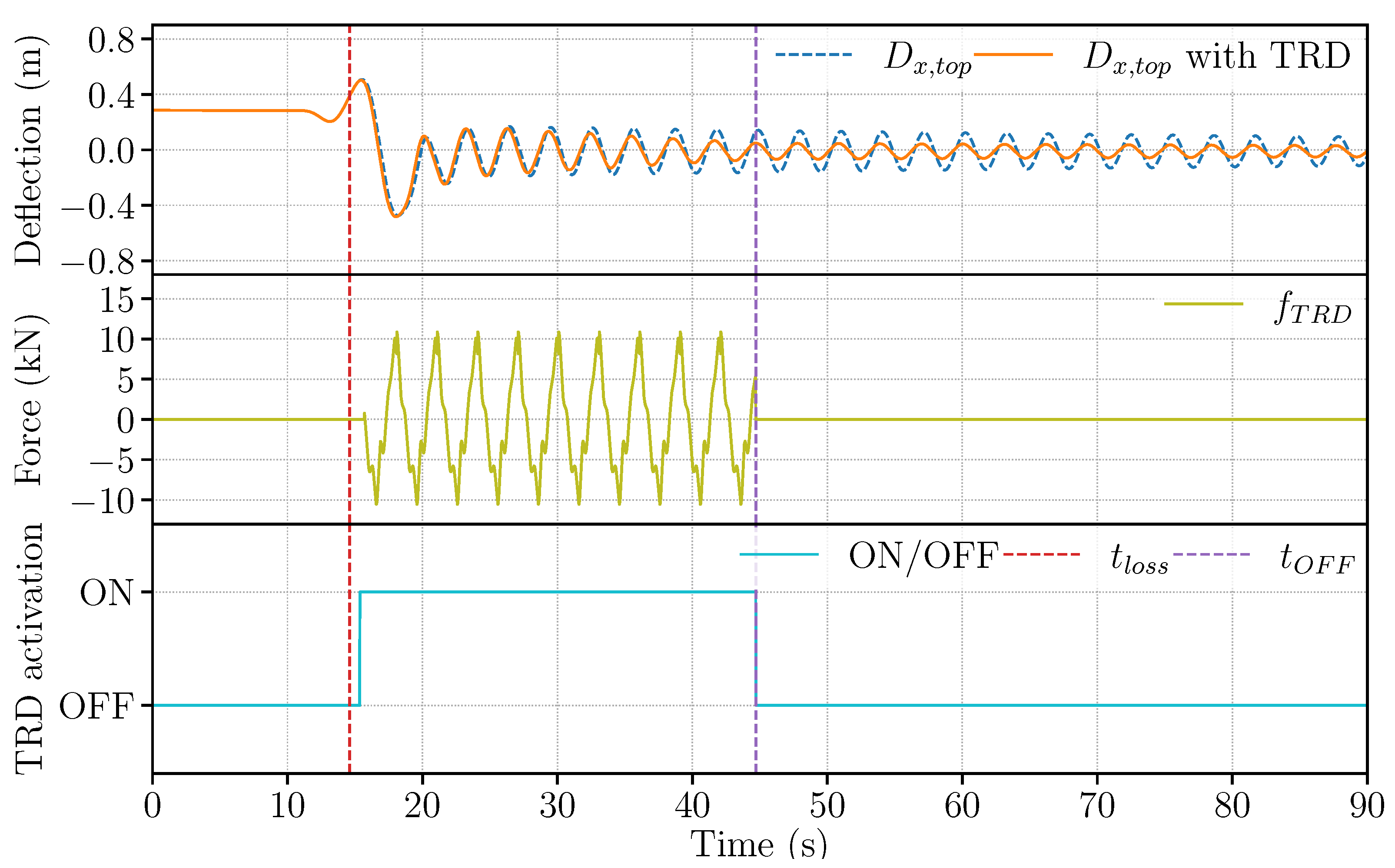
To ensure the function of TRD and prevent the re-excitation of the system, we proposed an event-based ON/OFF control for TRD due to its simplicity and efficiency (
Figure 6). It is a closed-loop control based on switching logic and has no intermediate state but only fully ON and fully OFF states. In other words, the control force from TRD
is instantly applied to the structure without any transition phase between the ON state and the OFF state.
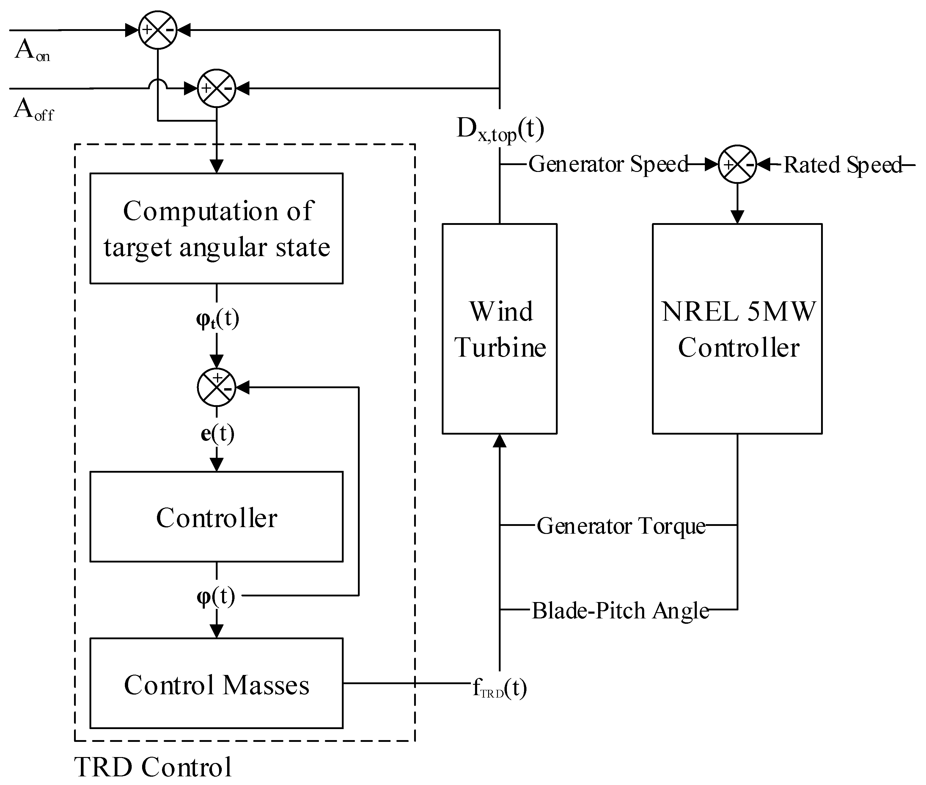
In
Figure 6, the default control system of NREL 5MW reference wind turbine [
41] is simplified on the right side while the proposed TRD control is represented on the left. The tower-top deflection
is computed and fed back to the controller of TRD. It is compared to two thresholds of vibration amplitude,
and
, in the way given in Algorithm 1.
| Algorithm 1. ON/OFF control of the TRD for the wind turbine tower. |
![Infrastructures 06 00162 i005]() |
The value of the threshold is set lower than . If the measured deflection falls below , the TRD is turned off to avoid the wind turbine being re-excited by the forces generated from the TRD. If exceeds , the TRD is turned back on to reduce vibrations of the wind turbine.
Recalling the major properties of NREL 5MW reference wind turbine given in
Table A1, the following properties in
Table 1 are set to the TRD.
Note that the TRD mass is approximately of the tower mass and of the total mass above ground. From the perspective of mass requirements, this is a feasible design. The TRD is supposed to be positioned on the tower-top (at height of ). The inner radius of the tower on the tower-top is , hence, the TRD-to-tower clearance (i.e., available space between the outer radius of TRD and the inner radius of the tower) is . This is a feasible TRD size from the perspective of space requirements.
The numerical configurations to model this reference wind turbine in FAST are retrieved from FAST certification tests [
40] except for the time-step, which is fixed to
based on preliminary sensitivity analysis.


