
Enhancing Flexural Strength of RC Beams with Different Steel–Glass Fiber-Reinforced Polymer Composite Laminate Configurations: Experimental and Analytical Approach


Abstract
1. Introduction
2. Research Significance
3. Specimens’ Characteristics
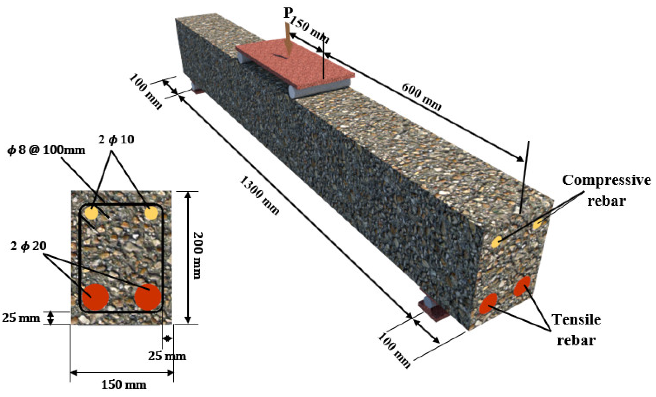
3.1. Geometric Dimensions and Boundary Condition
3.2. Concrete
3.3. GFRP Laminates
3.4. Steel Rebars
3.5. GFRP Rebars
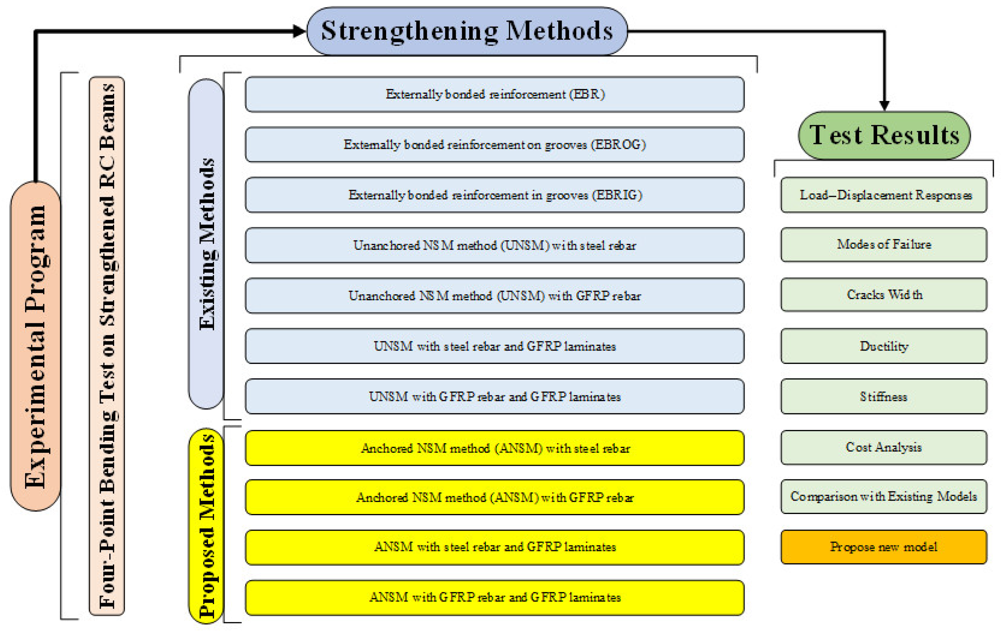
4. Strengthening Procedure
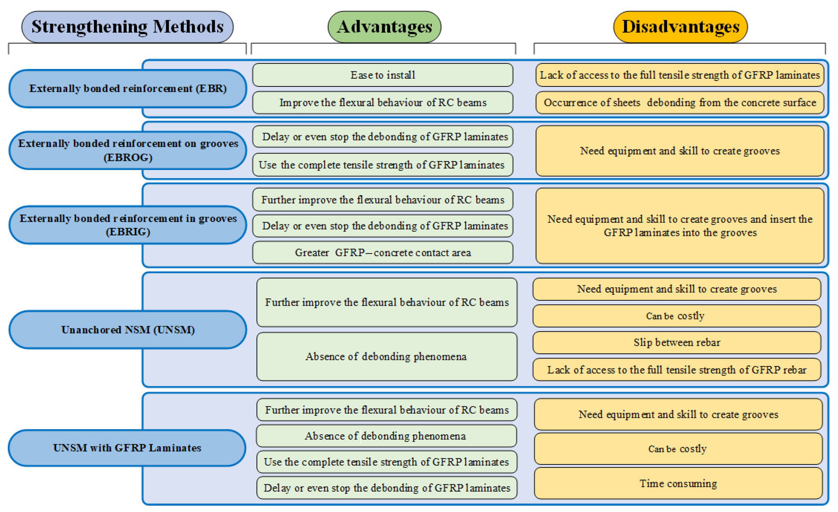
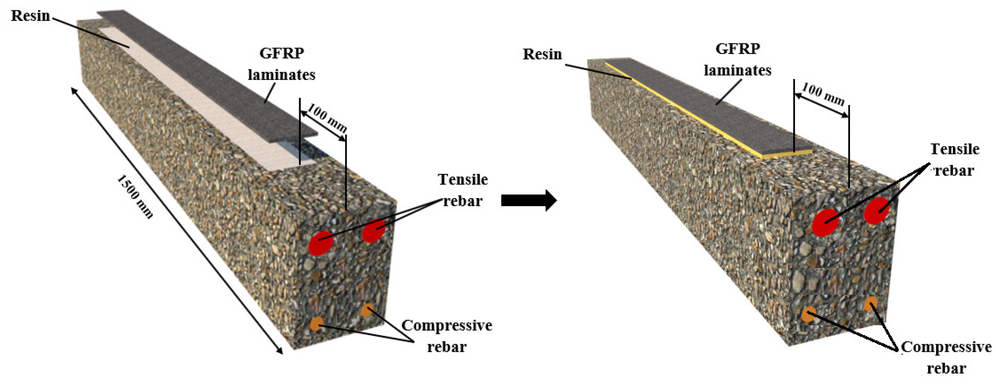
4.1. Externally Bonded Reinforcement (EBR)
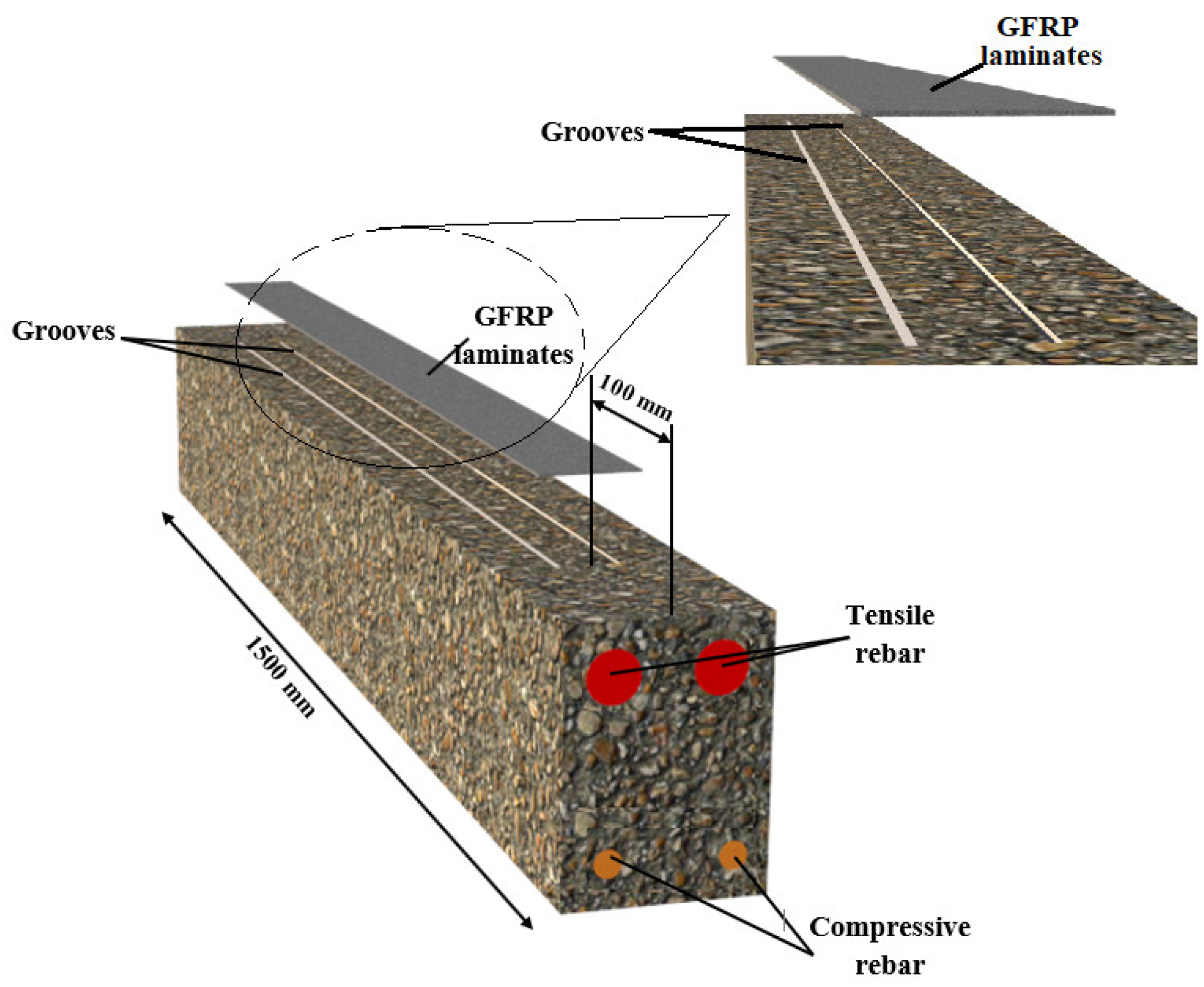
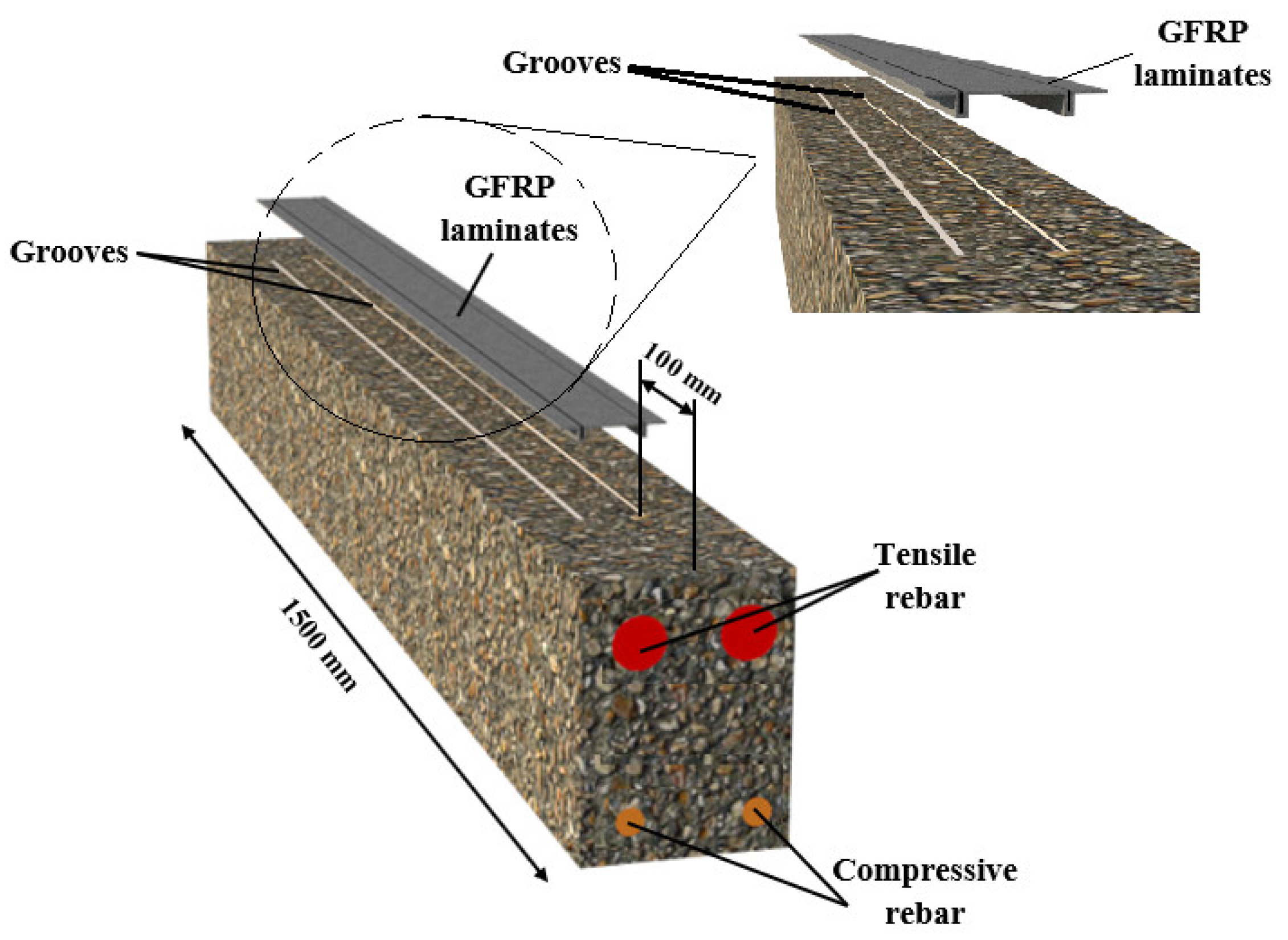
4.2. Externally Bonded Reinforcement on Grooves (EBROG)
4.3. Externally Bonded Reinforcement in Grooves (EBRIG)
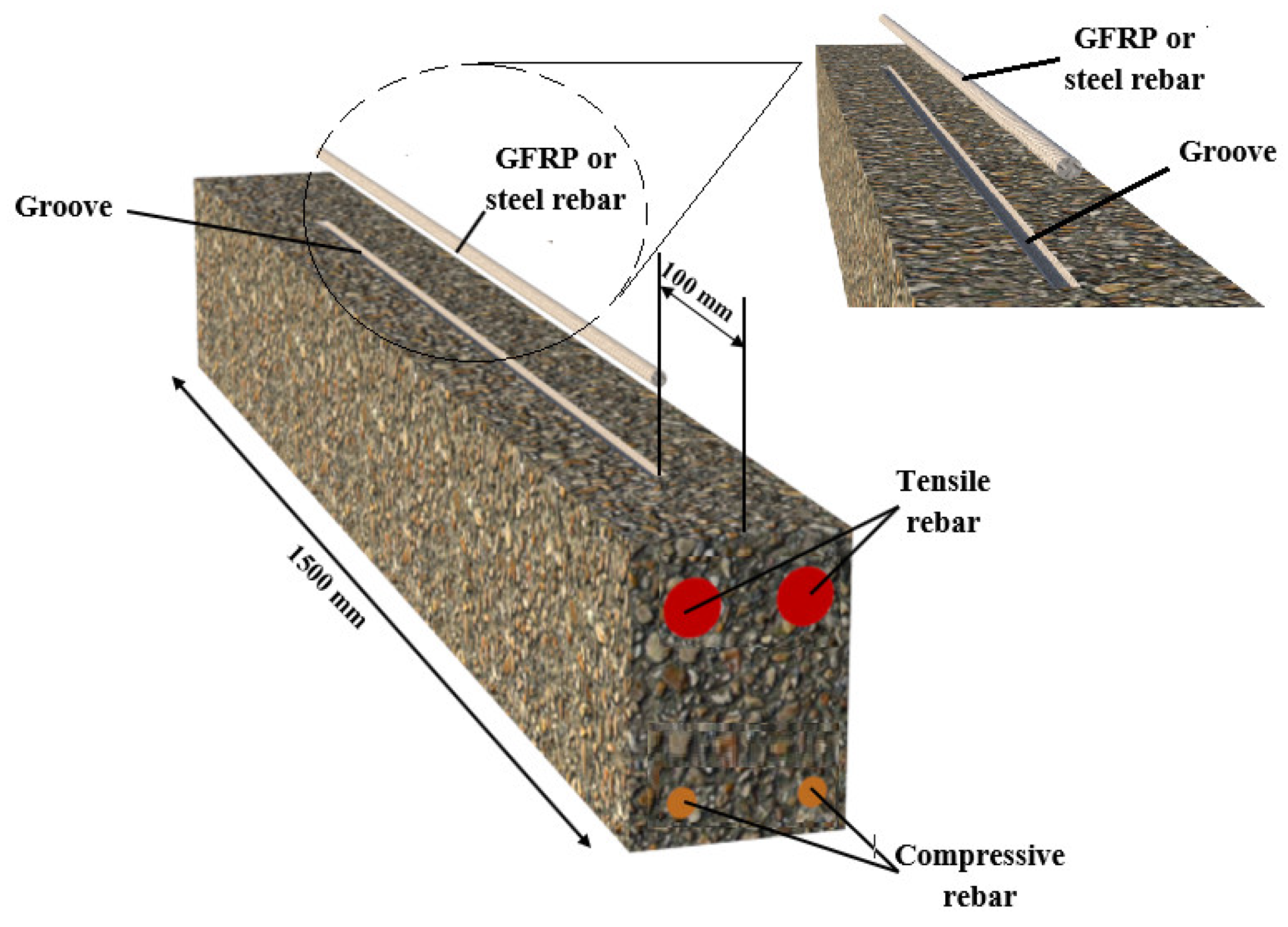
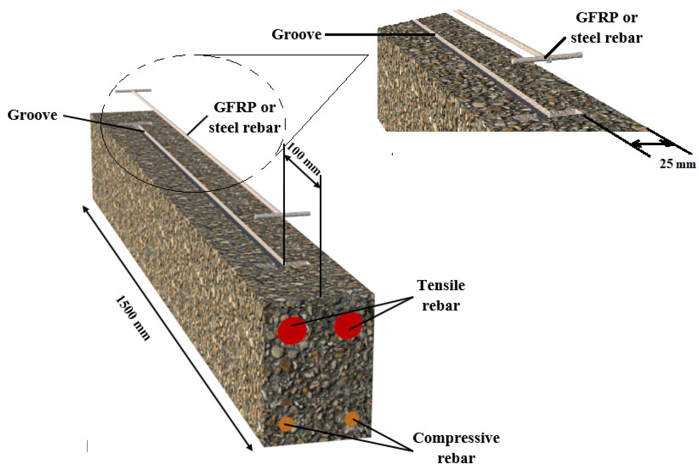
4.4. Unanchored NSM Method (UNSM)
4.5. Anchored NSM Method (ANSM)
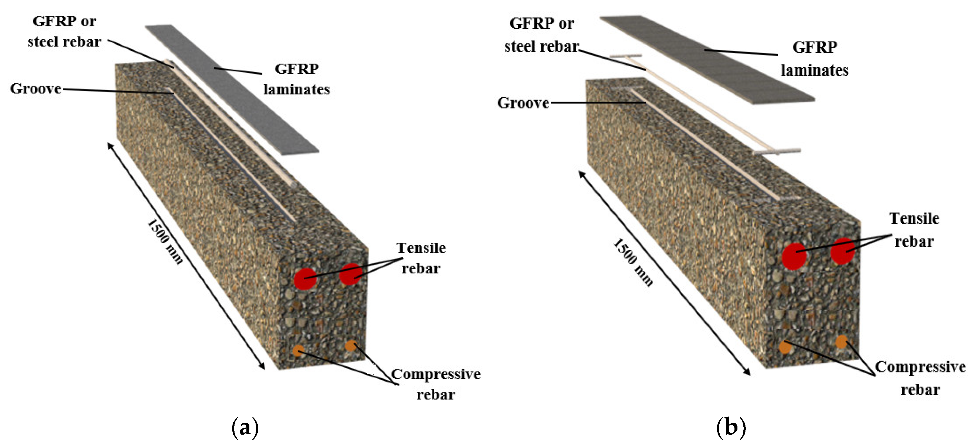
4.6. UNSM and ANSM with GFRP Laminates
5. Results and Discussion
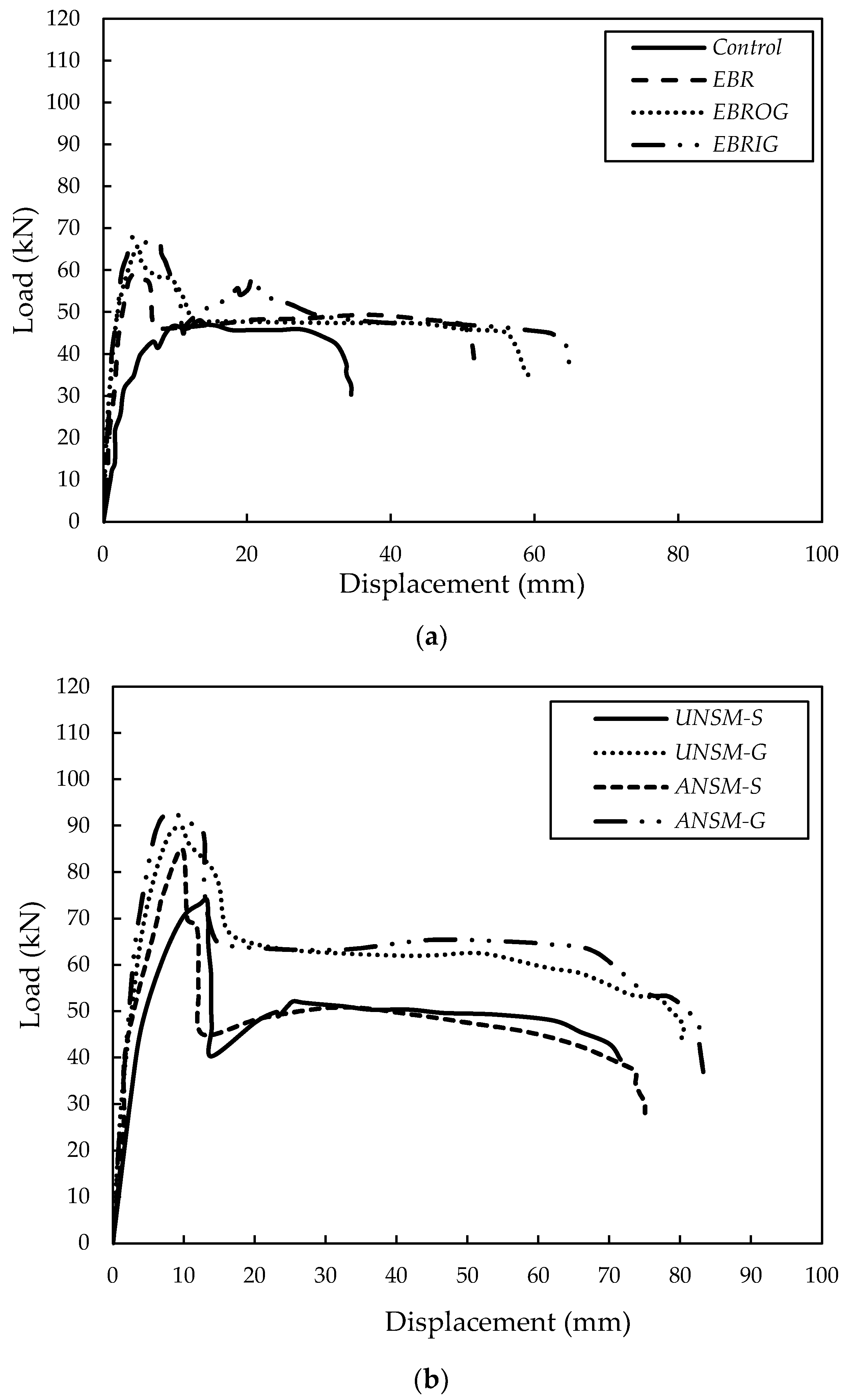
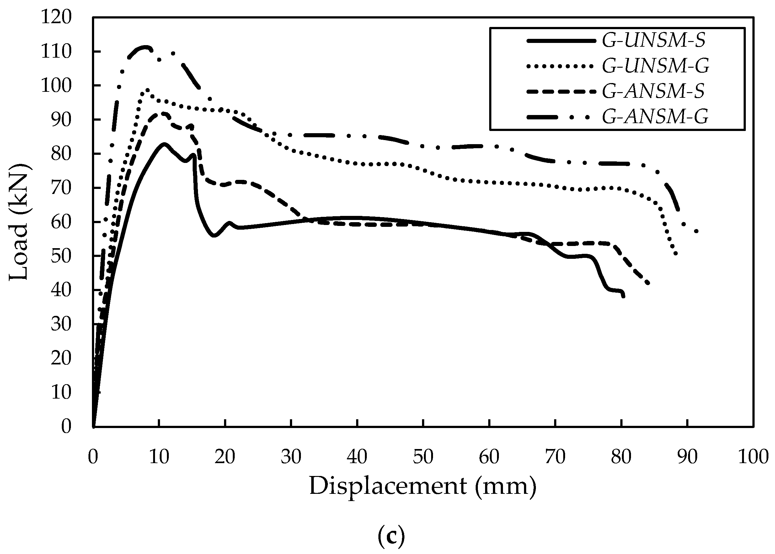
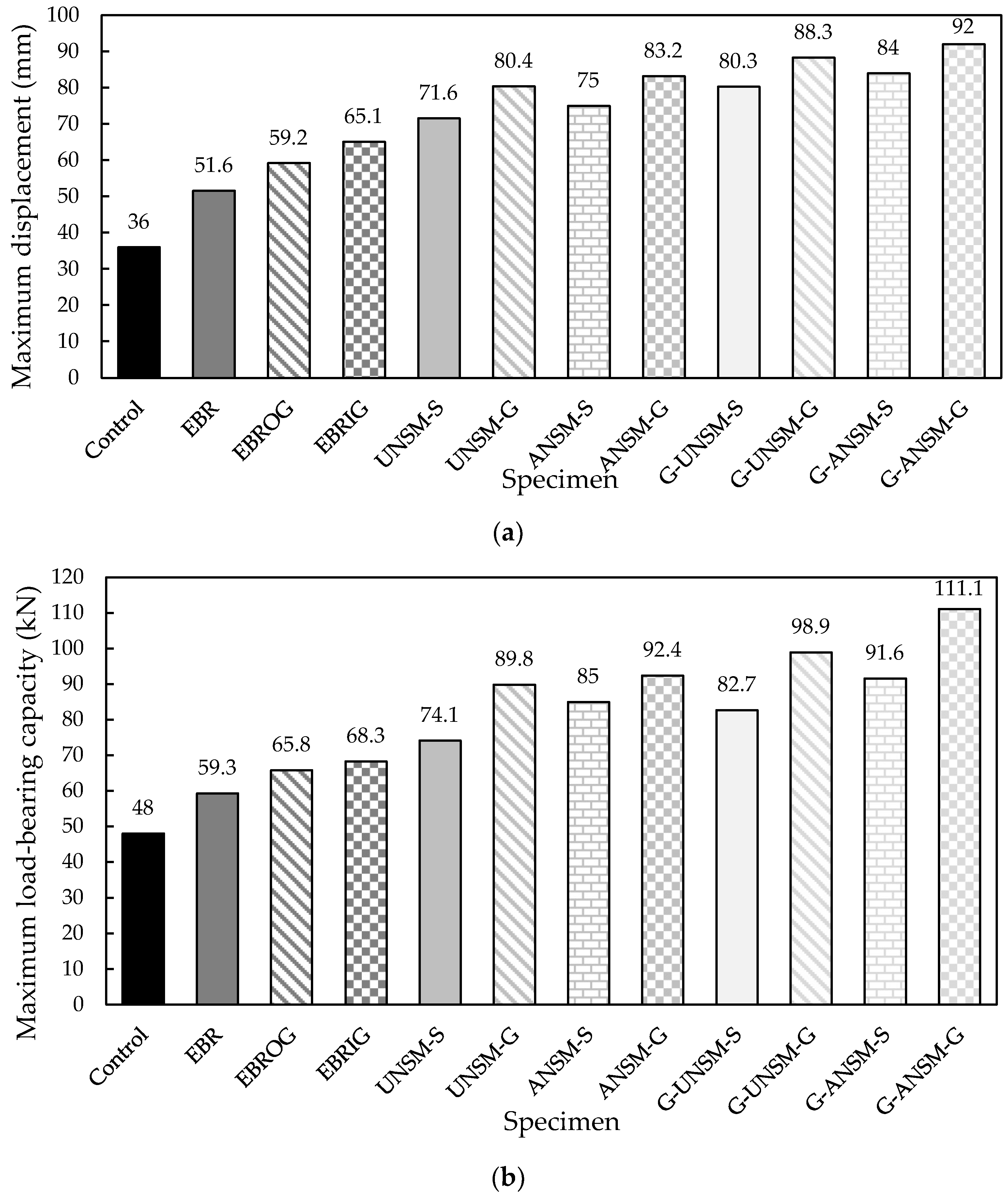
5.1. Load–Displacement Behavior
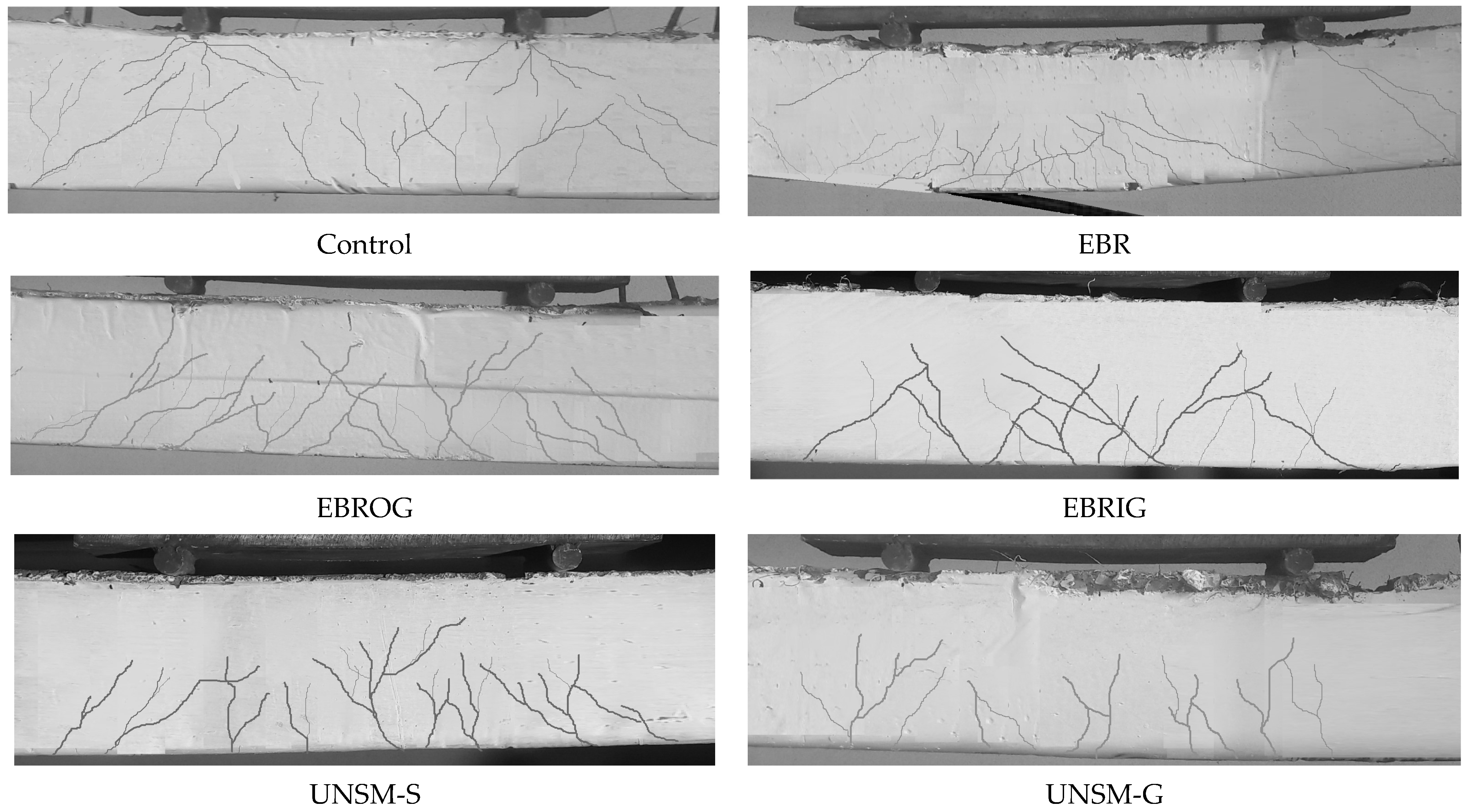
5.2. Modes of Failure
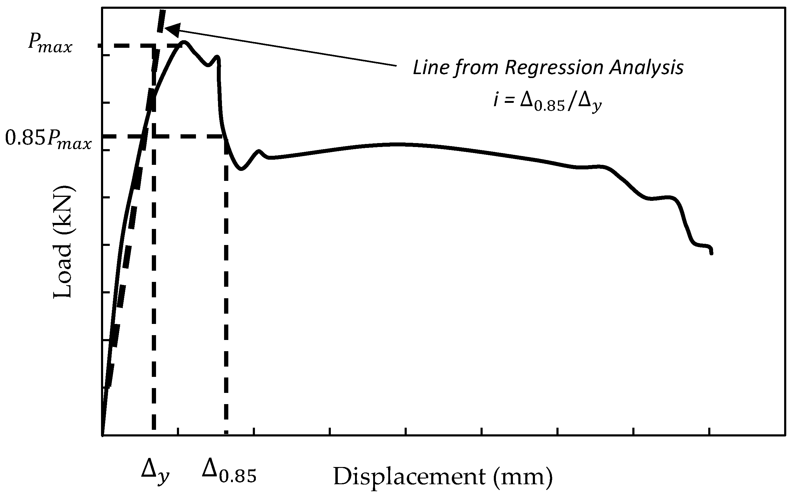
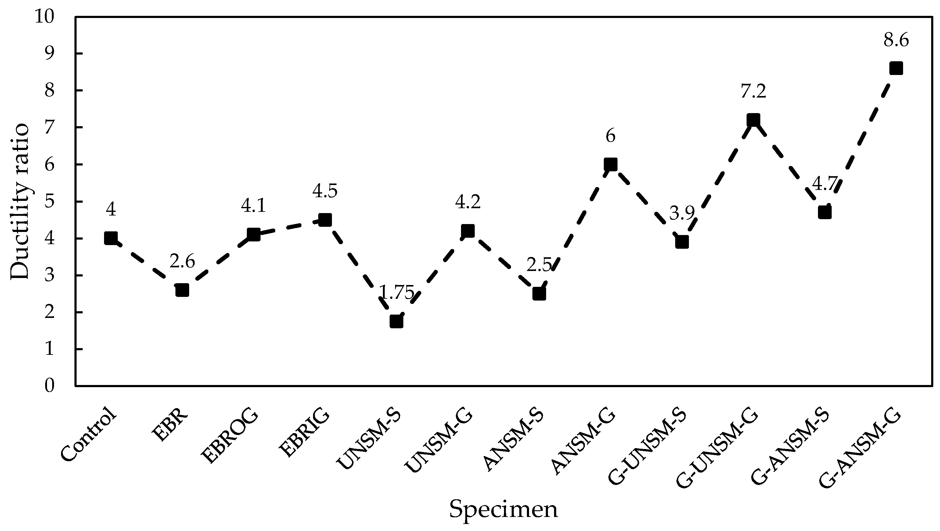
5.3. Ductility
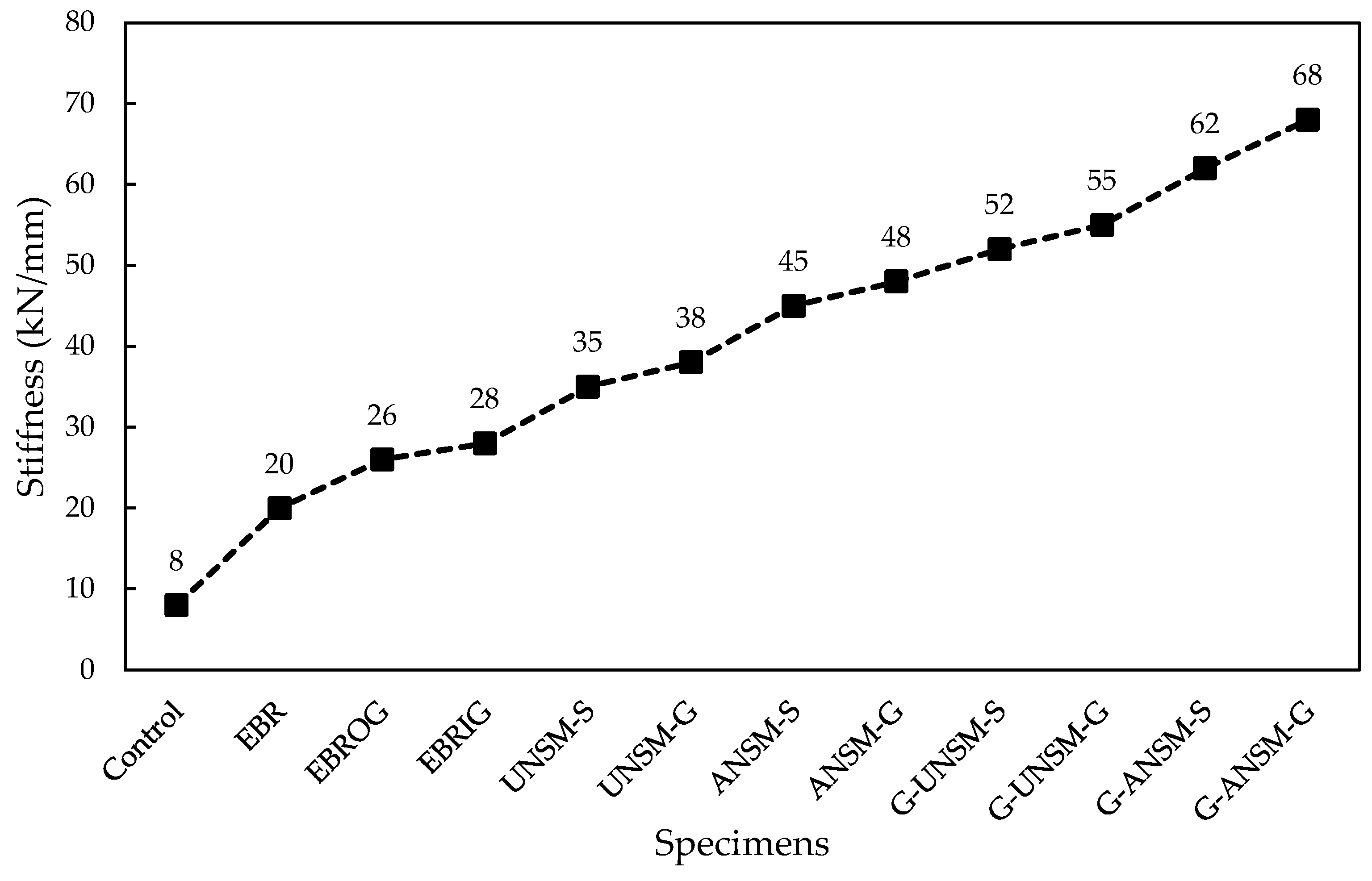
5.4. Stiffness
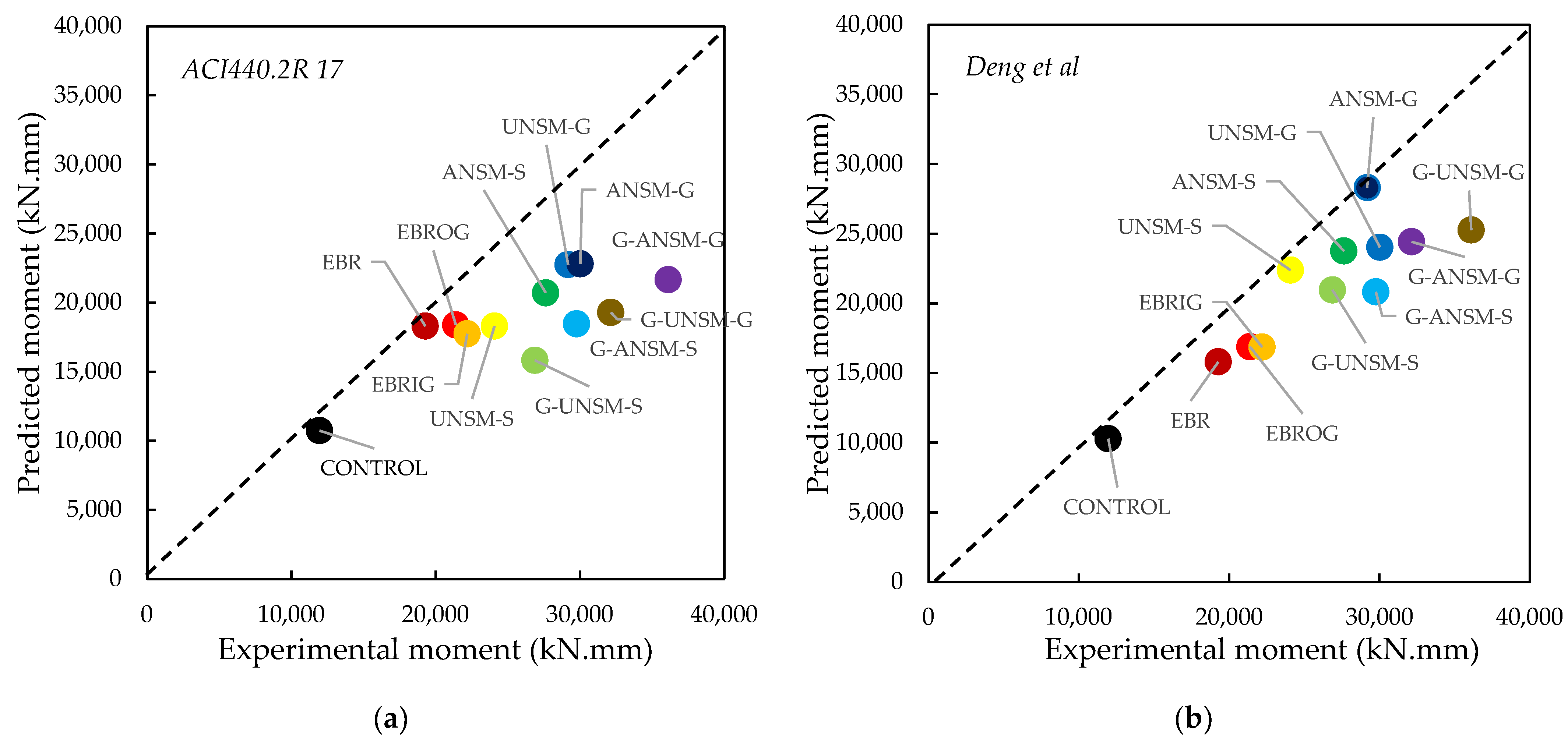
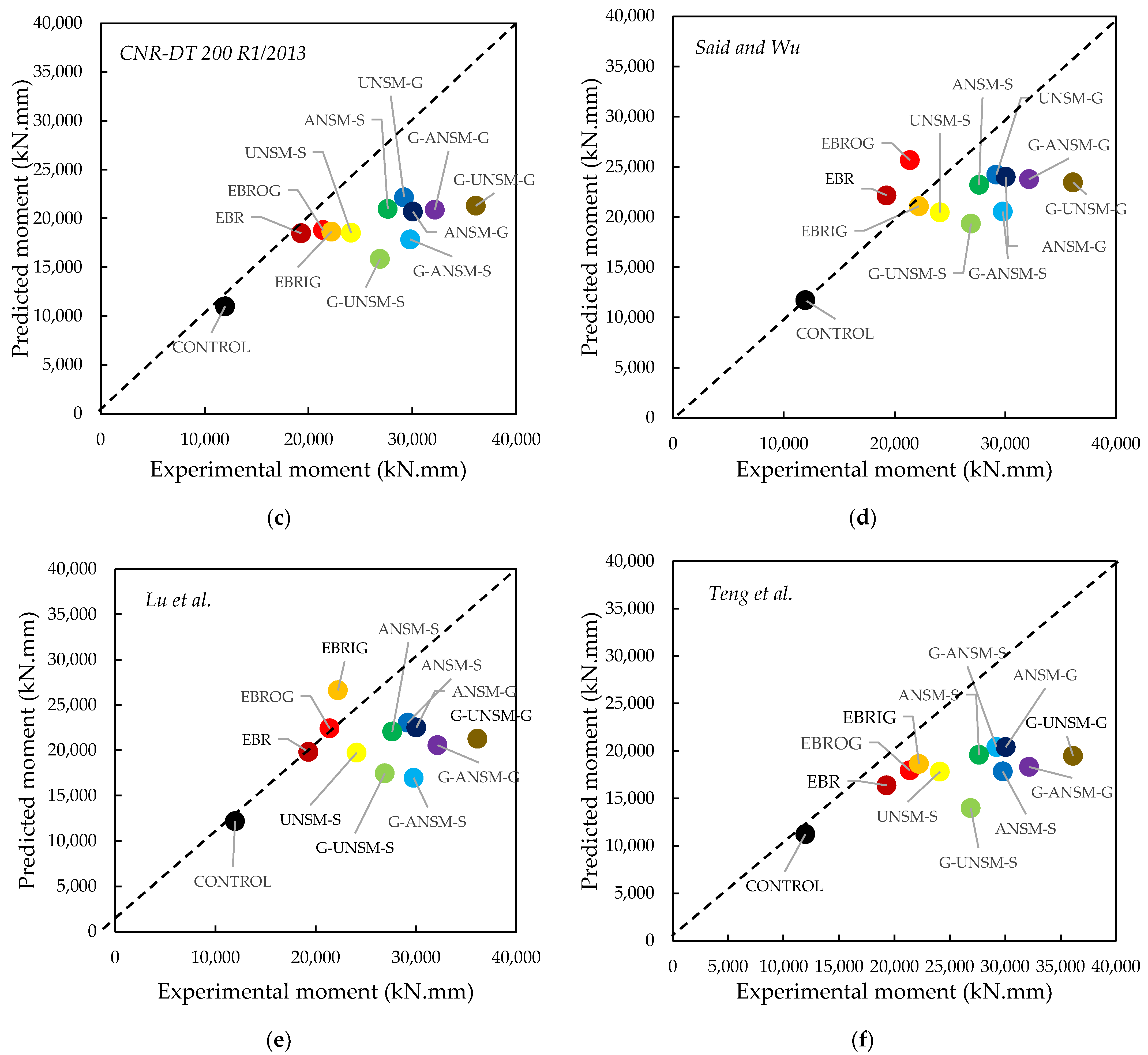
5.5. Comparison with Existing Standards
5.5.1. ACI440.2R 17
5.5.2. CNR-DT 200 R1/2013
5.5.3. Said and Wu
5.5.4. Lu et al.
5.5.5. Teng et al.
5.5.6. Deng et al.
- (1)
- During loading, the strengthened specimens comply with the assumption of a plane section.
- (2)
- The tensile resistance of concrete is neglected after cracking.
- (3)
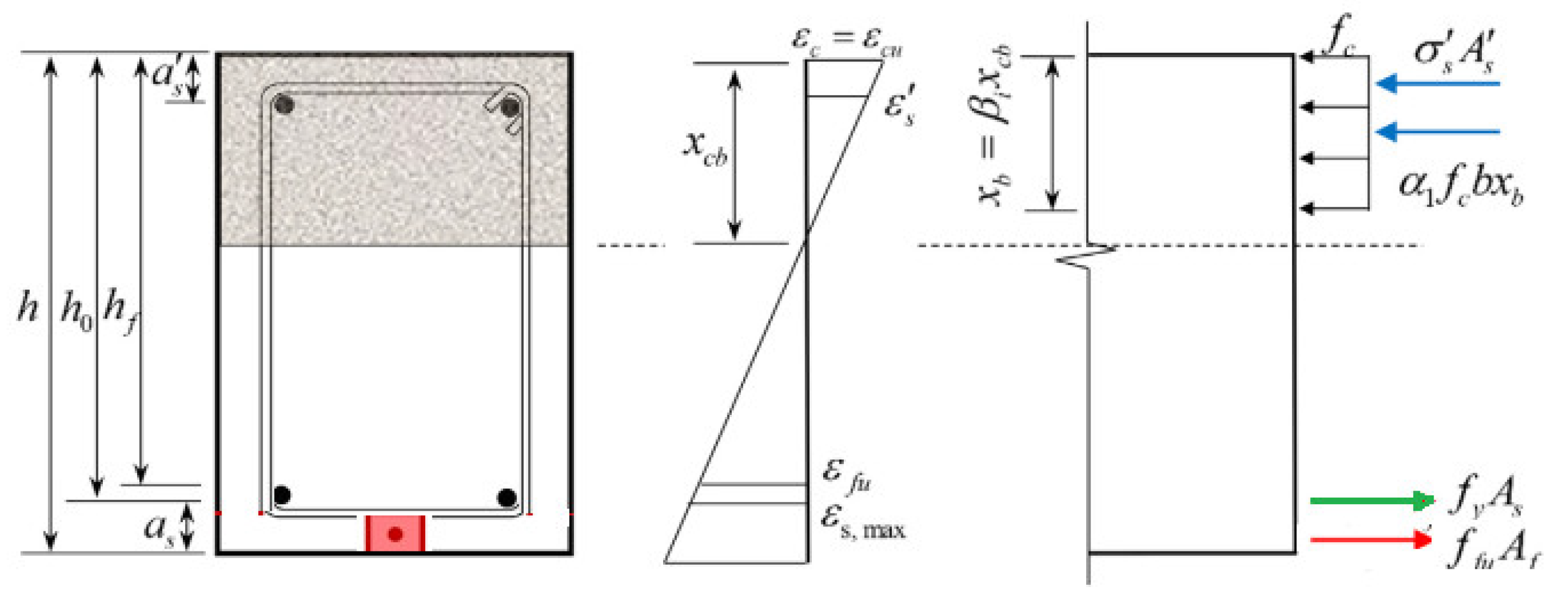
- The stress–strain curves of interior rebars can be shortened to a perfect elastic-plasticity behavior. In addition, the external strengthening rebar in the groove has a linear elastic stress–strain performance up to failure. is the maximum tensile strain of steel rebars, .
- (4)
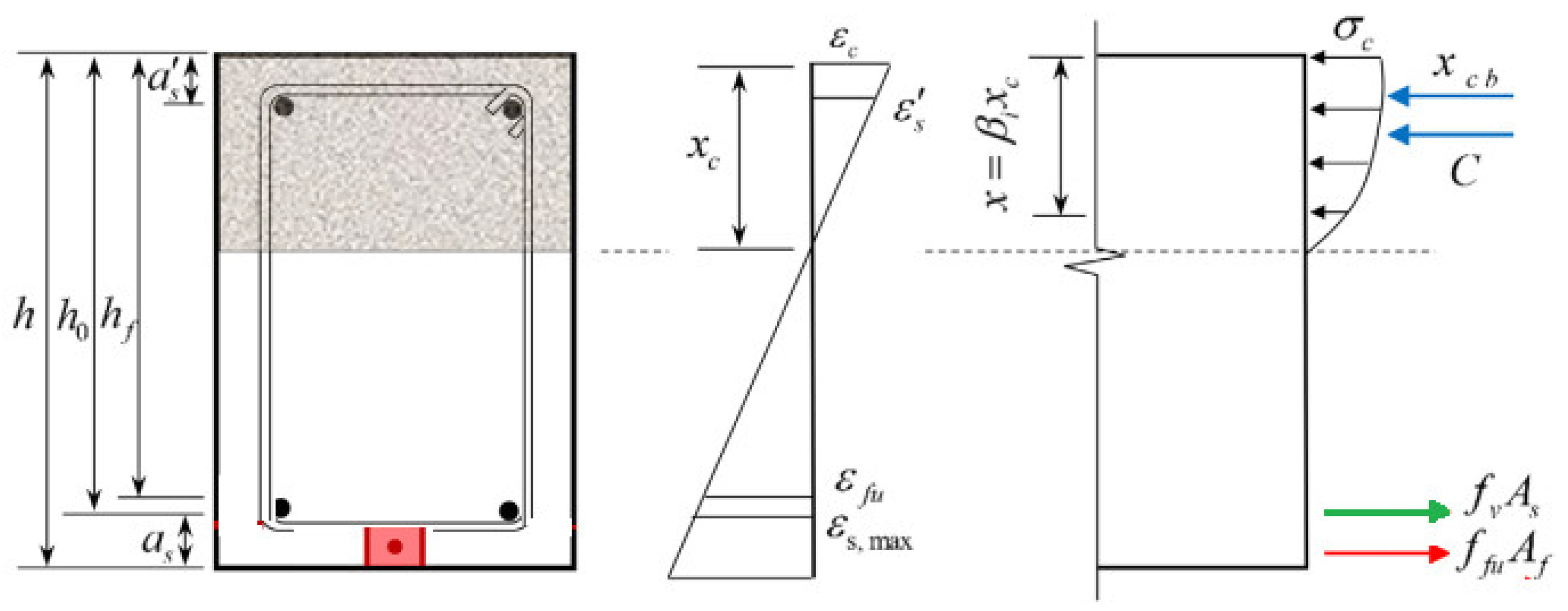
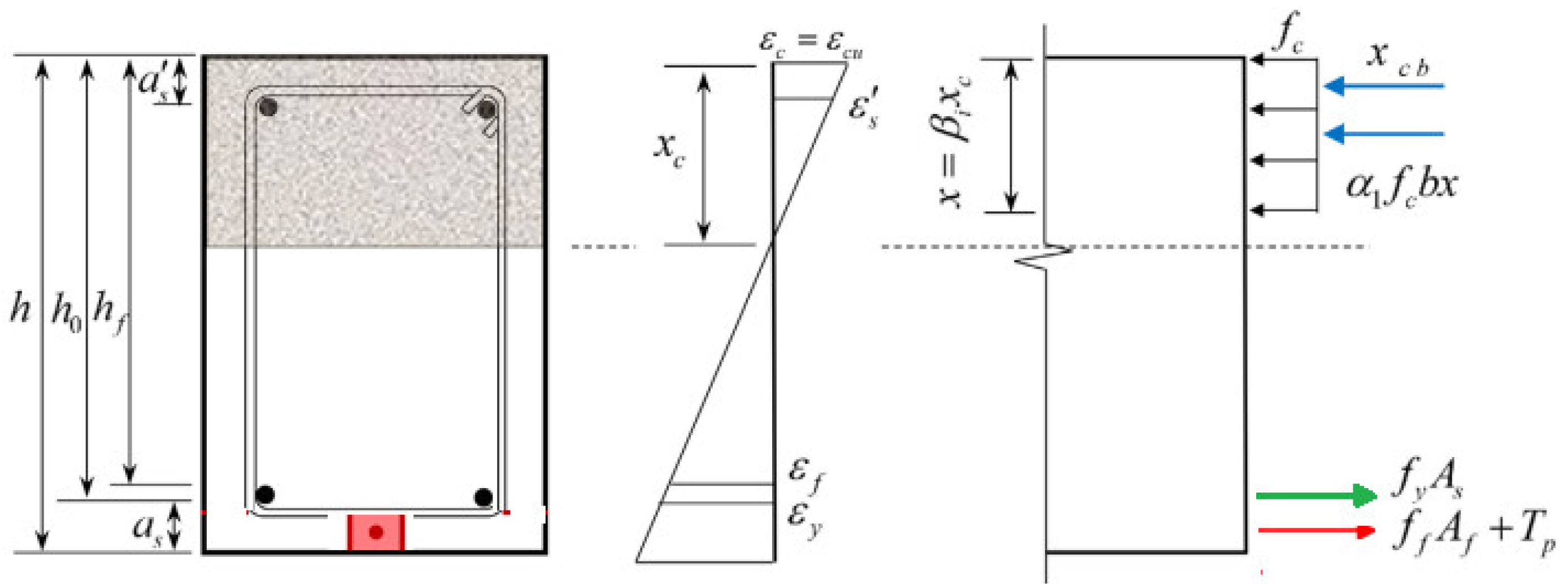
- The compression behavior of concrete is defined below:where is the compressive stress of concrete conforming to a given strain ; is the cylinder compressive resistance of concrete; is the compressive strain of concrete; is the compressive strain of concrete at the maximum stress value and equals 0.002; and is the maximum strain of compression concrete and equals 0.003. The balanced condition for strengthened beams using the NSM technique is reached when the concrete in compression achieves a final strain of 0.003 and the tensile strain in the external strengthening rebar reaches its ultimate tensile resistance [39]. The tensile steel rebars had already attained their maximum resistance at this time. The distribution of strain and stress throughout cross-section depth in the balanced condition is depicted in Figure 17. The following is an expression of the equation:where
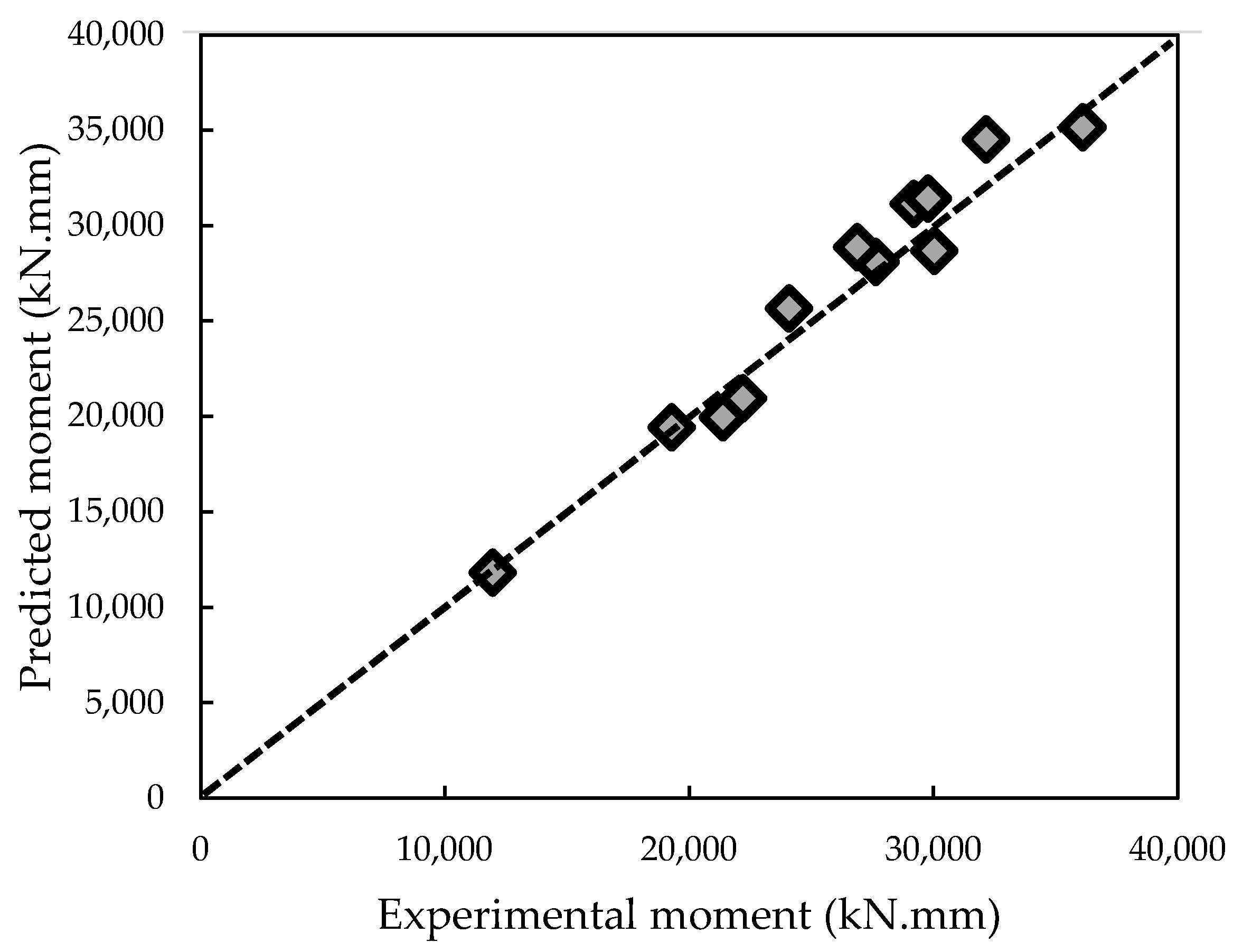
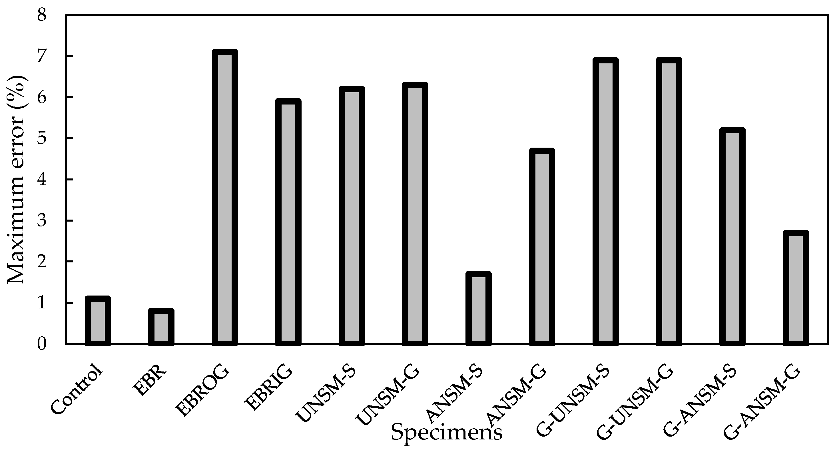
5.6. Proposed New Model
5.7. Cost Examination
6. Conclusions
- In terms of cost, there is no high difference between the total costs of various strengthening methods, and a maximum difference of USD 35 (9.7% relative to the control sample) was obtained when both GFRP laminates and GFRP rebar with two ends anchorage were used (G-ANSM-G). Therefore, the novel strengthening method of G-ANSM-G is recommended, since using both GFRP rebar and laminates led to the best flexural performance for the RC beam.
- However, the use of EBR, EBIRG, and EBROG meaningfully increased the load-carrying capacity and deformation of the RC beams; these responses were further enhanced when rebar was provided under the GFRP laminates, particularly if it was composed of GFRP. Among these, the newly proposed strengthening methods with the use of an anchorage I-shape rebar, ANSM-S, ANSM-G, G-ANSM-S, and G-ANSM-G showed the highest improvements in the bending resistance and deformation of RC beams, particularly when both the I-shape anchorage GFRP rebar and GFRP laminates were used.
- Debonding phenomena were observed in the EBR technique, which prevented the GFRP laminates from reaching the highest tensile strength; however, creating grooves led to an increase in the GFRP laminates’ engaged capacity. Therefore, with the use of EBROG and EBRIG, the crack widths decreased, and the initial cracking moments increased. In addition, the minimum crack width was observed when new G-ANSM-S and G-ANSM-G methods were used.
- Using novel techniques, not only was the debonding phenomenon eliminated, but also more GFRP strength was used to provide an anchorage that led to the best bending behavior of the RC beams in terms of initial crack width and cracking moment.
- The ductility of the RC beams decreased with the use of EBR, while using EBROG and EBRIG slightly improved ductility. Performing UNSM and ANSM using steel rebars decreased ductility, while using GFRP rebars improved it. Conversely, the highest ductility was observed when GFRP rebars and laminates were used simultaneously (G-UNSM-G and G-ANSM-G).
- The existing standards are unable to predict either the ultimate or initial cracking moments of RC beams strengthened with various GFRP laminate strengthening techniques, especially when the UNSM and ANSM techniques were used with and without GFRP rebars and laminates. However, the model proposed in the current examination with a high agreement with experimental findings can be utilized as a reliable tool to estimate the bending resistance of RC beams strengthened with various retrofitting practices.
Author Contributions
Funding
Data Availability Statement
Conflicts of Interest
Acronyms and Symbols:
| ANSM | Anchored NSM method |
| Tensile rebar cross-sectional area | |
| Compression rebar cross-sectional area | |
| FRP laminate area | |
| Active area of the external strengthening rebar | |
| Width of the GFRP laminates | |
| b | Width of beam section |
| c | Distance from final compression fibers to the neutral axis |
| FC | Confidence factor |
| CFRP | Carbon fiber-reinforced polymer |
| d | Distance from final compression fiber to the centroid of tensile rebars |
| d’ | Distance from the extreme compression fiber to the centroid of compression rebars |
| EBR | Externally bonded reinforcement |
| EBROG | Externally bonded reinforcement on grooves |
| EBRIG | Externally bonded reinforcement in grooves |
| Elastic moduli | |
| FRP | Fiber-reinforced polymer |
| Stress of the external strengthening rebar | |
| Final stress of the external strengthening rebar | |
| GFRP | Glass fiber-reinforced polymer |
| i | Ductility index |
| MF-EBR | Mechanically fastened and externally bonded reinforcement |
| Nominal bending resistance | |
| n | Number of used laminates |
| NSM | Near-surface mounted |
| OPC | Ordinary Portland cement |
| RC | Reinforced concrete |
| GFRP laminates thickness | |
| Load conforming to the external strengthening rebar | |
| UNSM | Unanchored NSM method |
| Distance among the tensile force of the steel rebars | |
| 85% of the maximum load on the post-peak region of the curve | |
| Displacement at the beam’s first yield | |
| Compressive strength of the concrete | |
| Tensile rebars stress | |
| Compression rebar stress | |
| GFRP laminates’ failure strain | |
| Effective depth of the GFRP laminates | |
| Reduction bending factor generated by GFRP | |
| Depth of the rectangular stress block to the depth of the neutral axis ratio | |
| Strain in the GFRP laminates | |
| Environmental factor | |
| Material safety factor | |
| Failure strain of the GFRP laminates | |
| Debonding strain of the GFRP laminates | |
| Safety factor | |
| Corrective factor | |
| Geometrical corrective factor | |
| Maximum of the GFRP laminates strain at debonding | |
| Force of the compression portion of the section including the distance between centroid of the tensile rebar and the centroid of the GFRP laminates | |
| Distance from the section to the end of the GFRP laminates | |
| Distance from the GFRP cutoff to the adjacent performed load | |
| Maximum tensile strain of steel rebars | |
| Compressive strain of concrete | |
| Compressive strain of concrete at the maximum stress | |
| Maximum strain of compression concrete | |
| Real depth of the neutral axis | |
| Depth of the equivalent rectangular compression stress block | |
| Proportion of the concrete resistance to the corresponding stress in the compression stress block | |
| Compressive force of concrete | |
| Effective stress in the external strengthening rebar when prestressing stress exists | |
| Tensile resistance of concrete | |
| ξ | Modification factors considering the influence of anchorage |
| ζ | Modification factors considering simultaneous external GFRP laminate installation |
References
- Yang, D.Y.; Frangopol, D.M.; Teng, J.G. Probabilistic life-cycle optimization of durability-enhancing maintenance actions: Application to FRP strengthening planning. Eng. Struct. 2019, 188, 340–349. [Google Scholar] [CrossRef]
- Yang, Y.; Wang, X.; Wu, Z. Life cycle cost analysis of FRP cables for long-span cable-supported bridges. Structures 2020, 25, 24–34. [Google Scholar] [CrossRef]
- Pour, A.K.; Edalati, M. Retrofitting of the corroded reinforced concrete columns with CFRP and GFRP fabrics under different corrosion levels. Eng. Struct. 2021, 228, 111523. [Google Scholar]
- Pour, A.K.; Ghalehnvoi, M.; Gencel, O. Torsional behaviour of rectangular high-performance fibre-reinforced concrete beams. Structures 2022, 35, 511–519. [Google Scholar]
- Farokhpour, A.; Ghalehnovi, M.; Karimipour, M. The behavior of concrete beams reinforced with polymer reinforcement and hybrid fibers. In Proceedings of the 10th National Conference of Concrete, Tehran, Iran, 7 October 2018. [Google Scholar]
- Pour, A.K. Experimental and numerical evaluation of steel fibres RC patterns influence on the seismic behaviour of the exterior concrete beam-column connections. Eng. Struct. 2022, 263, 114358. [Google Scholar] [CrossRef]
- Pour, A.K.; Farsangi, E.N. Health monitoring of recycled aggregates reinforced concrete beams retrofitted by concrete jacket using piezoelectric transducers. In Data-Centric Structural Health Monitoring; De Gruyte: Berlin, Germany, 2023. [Google Scholar]
- Kashi, A.; Ramezanianpour, A.A.; Moodi, F. Durability evaluation of retrofitted corroded reinforced concrete columns with FRP sheets in marine environmental conditions. Constr. Build. Mater. 2017, 151, 520–533. [Google Scholar] [CrossRef]
- Zhou, Y.; Chen, X.; Wang, X.; Sui, L.; Huang, X.; Guo, M. Seismic performance of large rupture strain FRP retrofitted RC columns with corroded steel reinforcement. Eng. Struct. 2020, 216, 110744. [Google Scholar] [CrossRef]
- Al-Nimry, H.; Soman, A. On the slenderness and FRP confinement of eccentrically-loaded circular RC columns. Eng. Struct. 2018, 164, 92–108. [Google Scholar] [CrossRef]
- Spadea, G.; Bencardino, F.; Swamy, R.N. Structural behaviour of composite RC beams with externally bonded CFRP. J. Compos. Constr. 1998, 2, 132–137. [Google Scholar] [CrossRef]
- Pimanmas, A.; Pornpongsaroj, P. Peeling behaviour of reinforced concrete beams strengthened with CFRP plates under various end restraint conditions. Mag. Concr. Res. 2004, 56, 73–81. [Google Scholar] [CrossRef]
- Toutanji, H.; Zhao, L.Z.; Zhang, Y. Flexural behavior of reinforced concrete beams externally strengthened with CFRP sheets bonded with an inorganic matrix. Eng. Struct. 2006, 28, 557–566. [Google Scholar] [CrossRef]
- Galecki, G.; Marez, N.; Nanni, A.; Myers, J. Limitations to the use of waterjets in concrete substrate preparation. In Proceedings of the 2001 WJTA American Waterjet Conference, Minneapolis, MN, USA, 18–21 August 2001. [Google Scholar]
- Rezaiee-Pajand, M.; Pour, A.K. Three stress-based triangular elements. Eng. Comput. 2019, 36, 1325–1345. [Google Scholar] [CrossRef]
- Pour, A.K.; Shirkhani, A.; Zeng, J.-J.; Zhuge, Y.; Farsangi, E.N. Experimental investigation of GFRP-RC beams with Polypropylene fibers and waste granite recycled aggregate. Structures 2023, 50, 1021–1034. [Google Scholar] [CrossRef]
- Pour, A.K.; Shirkhani, A.; Farsangi, E.N. Influence of Fiber Type on the Performance of Reinforced Concrete Beams Made of Waste Aggregates: Experimental, Numerical and Cost Analyses. Pract. Period. Struct. Des. Constr. 2023, 28, 04023007. [Google Scholar] [CrossRef]
- Pour, A.K.; Shirkhani, A.; Hamzehkolaei, N.S.; Zhuge, Y.; Farsangi, E.N. Performance evaluation of composite concrete-flled steel tube columns by steel fbers and different cross-section shapes: Experimental and numerical investigations. J. Constr. Steel Res. 2023, 200, 107656. [Google Scholar] [CrossRef]
- Pour, A.K.; Shirkhani, A.; Kirgiz, M.S.; Farsangi, E.N. Experimental investigation of GFRP-reinforced concrete columns made with waste aggregates under concentric and eccentric loads. Struct. Concr. 2022, 24, 1670–1688. [Google Scholar] [CrossRef]
- Farokhpour, A.; Ghalehnovi, M.; Pour, A.K. Structural Performances of Concrete Beams with Hybrid, Fiber-Reinforced Polymer-Steel Reinforcements. In Proceedings of the 7th National and 3th International Conference in Civil Engineering, Fredericton, NB, Canada, 13–16 June 2018. [Google Scholar]
- Chaboki, H.R.; Ghalehnovi, M.; Pour, A.K. Investigation of shear behavior of concrete beams made of recycled aggregate. Archit. Urban Manag. 2018. [Google Scholar]
- Pour, A.K.; Chaboki, H.R.; Ghalehnovi, M. Investigation of flexural behavior of concrete beams made of recycled aggregate. Concr. Res. Q. J. 2019, 10, 45–68. [Google Scholar]
- Mostofinejad, D.; Mahmoudabadi, E. Grooving as an alternative method of surface preparation to postpone debonding of FRP laminates in concrete beams. J. Compos. Constr. 2010, 6, 804–811. [Google Scholar] [CrossRef]
- Ghaleh, R.Z.; Mostofinejad, D. Behaviour of EBRIG CFRP sheet-concrete joint: Comparative assess-ment with EBR and EBROG methods. Constr. Build. Mater. 2002, 346, 128374. [Google Scholar] [CrossRef]
- Mukhtar, F.M. Customized shear test for bond-slip characterization of EBR FRP-concrete system: Influence of substrate aggregate type. Compos. Part B Eng. 2019, 163, 606–621. [Google Scholar] [CrossRef]
- Mostofinejada, D.; Shamelia, S.M.; Hosseini, A. EBROG and EBRIG methods for strengthening of RC beams by FRP sheets. Eur. J. Environ. Civ. Eng. 2014, 18, 652–668. [Google Scholar] [CrossRef]
- Moshiri, N.; Czaderski, C.; Mostofinejad, D.; Motavalli, M. Bond resistance of prestressed CFRP strips attached to concrete by using EBR and EBROG strengthening methods. Constr. Build. Mater. 2021, 266, 121209. [Google Scholar] [CrossRef]
- Arabzadeh, A.; Karimizadeh, H. Experimental study of RC deep beams with opening and FRP composites installed by means of EBR and EBROG methods. Constr. Build. Mater. 2019, 208, 780–791. [Google Scholar] [CrossRef]
- Mostofinejad, D.; Shameli, M. Performance of EBROG method under multilayer FRP sheets for flexural strengthening of concrete beams. Procedia Eng. 2011, 14, 3176–3182. [Google Scholar] [CrossRef]
- Mostofinejad, D.; Shameli, S.D. Externally bonded reinforcement in grooves (EBRIG) technique to postpone debonding of FRP sheets in strengthened concrete beams. Constr. Build. Mater. 2013, 38, 751–758. [Google Scholar] [CrossRef]
- Sena-Cruz, J.M.; Barros, J.A.O.; Coelho, M.R.F.; Silva, L.F.F.T. Efficiency of different techniques in the flexural strengthening of RC beams under monotonic and fatigue loading. Constr. Build. Mater. 2012, 29, 175–182. [Google Scholar] [CrossRef]
- El-Hacha, R.; Rizkalla, S. Near-surface-mounted fibre reinforced polymer reinforcement for flexural strengthening of concrete structures. ACI Struct. 2004, 101, 717–726. [Google Scholar]
- Ceroni, F. Experimental performances of RC beams strengthened with FRP materials. Constr. Build. Mater. 2010, 95, 1547–1559. [Google Scholar] [CrossRef]
- Nordin, H.; Taljsten, B. Concrete beams strengthened with prestressed NSM CFRP. J. Compos. Constr. 2006, 10, 60–68. [Google Scholar] [CrossRef]
- Jalali, M.; Sharbatdar, M.K.; Fei-Chen, J.; Alaee, F.J. Shear strengthening of RC beams using innovative manually made NSM FRP bars. Constr. Build. Mater. J. 2011, 36, 990–1000. [Google Scholar] [CrossRef]
- Chaboki, H.R.; Ghalehnovi, M.; Karimi, A. Study of the Flexural behaviour of recycled aggregate concrete beams. J. Concr. Res. 2019, 12, 45–60. [Google Scholar]
- Pour, A.K.; Farsangi, E.N. Experimental evaluation of concrete having Fly Ash and recycled asphalt aggregates for infrastructure constructions. J. Appl. Sci. Eng. 2024, 7, 159. [Google Scholar]
- Karimi, A.; Mohebbi Najm Abad, J.; Fasihihour, N. Predicting the load-carrying capacity of GFRP-reinforced concrete columns using ANN and evolutionary strategy. Compos. Struct. 2021, 275, 114470. [Google Scholar]
- Deng, Y.; Li, Z.; Zhang, H.; Corigliano, A.; Angus, C.C.; Lam, A.C.C.; Hansapinyo, C.; Yan, Z. Experimental and analytical investigation on flexural behaviour of RC beams strengthened with NSM CFRP prestressed concrete prisms. Compos. Struct. 2021, 257, 113385. [Google Scholar] [CrossRef]
- Zhang, Y.; Elsayed, M.; Zhang, L.V.; Nehdi, M.L. Flexural behaviour of reinforced concrete T-section beams strengthened by NSM FRP bars. Eng. Struct. 2021, 233, 111922. [Google Scholar] [CrossRef]
- Barris, C.; Sala, P.; Gómez, J.; Torres, L. Flexural behaviour of FRP reinforced concrete beams strengthened with NSM CFRP strips. Compos. Struct. 2020, 241, 112059. [Google Scholar] [CrossRef]
- Al-Abdwais, A.H.; Al-Mahaidi, R.S. Performance of reinforced concrete beams strengthened with NSM CFRP composites for flexure using cement-based adhesives. Structures 2020, 27, 1446–1457. [Google Scholar] [CrossRef]
- Al-Obaidi, S.; Saeed, Y.M.; Rad, F.N. Flexural strengthening of reinforced concrete beams with NSM-CFRP bars using mechanical interlocking. J. Build. Eng. 2020, 31, 101422. [Google Scholar] [CrossRef]
- Rimkusa, A.; Cervenkab, V.; Gribniaka, V.; Cervenka, J. Uncertainty of the smeared crack model applied to RC beams. Eng. Fract. Mech. 2020, 233, 107088. [Google Scholar] [CrossRef]
- De Maio, U.; Greco, F.; Lonetti, P.; Pranno, A. A combined ALE-cohesive fracture approach for the arbitrary crack growth analysis. Eng. Fract. Mech. 2024, 301, 109996. [Google Scholar] [CrossRef]
- Soleimani Borujerdi, A.; Mostofinejad, D.; Hwang, H.J. Cyclic loading test for shear-deficient reinforced concrete exterior beam-column joints with high-strength bars. Eng. Struct. 2021, 237, 112140. [Google Scholar] [CrossRef]
- BS EN 12390-33; Testing Hardened Concrete: Compressive Strength of Test Specimens. British Standards Institution: London, UK, 2009.
- Ospina Cadavid, M.; Al-Khudairi, O.; Hadavini, H.; Liaghat, G. Experimental studies of stiffness degradation and dissipated energy in glass fibre reinforced polymer composite under fatigue loading. Polym. Polym. Compos. 2017, 25, 435–446. [Google Scholar]
- Jadee, K.J.; Othman, A.R. Analysis of stress mitigation through defence hole system in GFRP composite bolted joint. Am. J. Mech. Eng. 2015, 3, 126–134. [Google Scholar]
- ASTM A615/A615M-20; Standard Specification for Deformed and Plain Carbon Steel Bars for Concrete Reinforcement. ASTM International: West Conshohocken, PA, USA, 2020.
- ASTM D7957/D7957M-17; Standard Specification for Solid Round Glass Fibre Reinforced Polymer Bars for Concrete Reinforcement. ASTM International: West Conshohocken, PA, USA, 2017.
- Toutanji, H.; Ortiz, G. The effect of surface preparation on the bond interface between FRP sheets and concrete members. Compos. Struct. 2001, 53, 457–462. [Google Scholar] [CrossRef]
- Barros, J.A.; Dias, S.J.; Lima, J.L. Efficacy of CFRP-based techniques for the flexural and shear strengthening of concrete beams. Cem. Concr. Compos. 2007, 29, 203–217. [Google Scholar] [CrossRef]
- Maalej, M.; Leong, K.S. Effect of beam size and FRP thickness on interfacial shear stress concentration and failure mode of FRP-strengthened beams. Compos. Sci. Technol. 2005, 65, 1148–1158. [Google Scholar] [CrossRef]
- Mostofinejad, D.; Moghaddas, A. Bond efficiency of EBR and EBROG methods in different flexural failure mechanisms of FRP strengthened RC beams. Constr. Build. Mater. 2014, 54, 605–614. [Google Scholar] [CrossRef]
- Mostofinejad, D.; Akhlaghi, A. Experimental investigation of the efficacy of EBROG method in seismic rehabilitation of deficient reinforced concrete beam-column joints using CFRP sheets. J. Compos. Constr. 2016, 21, 04016116. [Google Scholar] [CrossRef]
- Sharaky, I.A.; Torres, L.; Comas, J.; Barris, C. Flexural response of reinforced concrete (RC) beams strengthened with near-surface mounted (NSM) fibre reinforced polymer (FRP) bars. Compos. Struct. 2014, 109, 8–22. [Google Scholar] [CrossRef]
- ACI 440.2R-17; Guide for the Design and Construction of Externally Bonded FRP Systems for Strengthening Concrete Structures. Report by ACI Committee 440. American Concrete Institute: Michigan, MI, USA, 2017.
- Karayannis, C.G.; Kosmidou, P.M.K.; Chalioris, C.E. Reinforced concrete beams with carbon-fibre-reinforced polymer bars—Experimental study. Fibers 2018, 6, 99. [Google Scholar] [CrossRef]
- Cohn, M.Z.; Bartlett, M. Computer-simulated flexural test of the partially pre-stressed concrete section. J. Struct. Div. 1982, 5, 2747–2765. [Google Scholar] [CrossRef]
- Pour, A.K.; Esfahani, M.R. The Effect of Steel Fibers on Flexural Cracking of Fiber in Reinforced Concrete Beams with Lap-spliced Bars. Ferdowsi Univ. J. Civ. Eng. 2017, 31, 1–18. [Google Scholar]
- Pour, A.K.; Ghalehnovi, M. New model for the lap-splice length of tensile reinforcement in concrete elements. J. Struct. Eng. 2021, 147, 12. [Google Scholar]
- Antino, T.D.; Pisani, M.A. Evaluation of the effectiveness of current guidelines in determining the strength of RC beams retrofitted by means of NSM reinforcement. Compos. Struct. 2017, 167, 166–177. [Google Scholar] [CrossRef]
- CNR-DT 200 R1/2013; Guide for the Design and Construction of Externally Bonded FRP Systems for Strengthening Existing Structures. National Research, Council: Rome, Italy, 2013.
- Said, H.; Wu, Z. Evaluating and proposing models of predicting IC debonding failure. J. Compos. Constr. 2008, 12, 284–299. [Google Scholar] [CrossRef]
- Lu, X.Z.; Teng, J.G.; Ye, L.P.; Jiang, J.J. Intermediate crack debonding in FRP-strengthened RC beams: FE analysis and strength model. J. Compos. Constr. 2007, 11, 161–174. [Google Scholar] [CrossRef]
- Teng, J.G.; Smith, S.T.; Yao, J.; Chen, J.F. Intermediate crack-induced debonding in RC beams and slabs. Constr. Build. Mater. 2003, 17, 447–462. [Google Scholar] [CrossRef]
- ACI 318–319; Building Code Requirements for Structural Concrete and Commentary. American Concrete Institute: Michigan, MI, USA, 2016; Report 624.
- Wang, W.W. Technology and Application of FRP Reinforced Concrete Structures; China Construction Industry Press: Beijing, China, 2007. [Google Scholar]

| Specimen | Grooves | Rebars in Groove | GFRP Laminates |
|---|---|---|---|
| Control | - | - | - |
| EBR | - | - | GFRP |
| EBROG | Two parallel | - | GFRP |
| EBRIG | Two parallel | - | GFRP |
| UNSM-S | One | Steel | - |
| UNSM-G | One | GFRP | - |
| ANSM-S | One | Steel | - |
| ANSM-G | One | GFRP | - |
| G-UNSM-S | One | Steel | GFRP |
| G-UNSM-G | One | GFRP | GFRP |
| G-ANSM-S | One | Steel | GFRP |
| G-ANSM-G | One | GFRP | GFRP |
| Cement | Water | Coarse Aggregates | Fine Aggregates |
|---|---|---|---|
| 300 | 190 | 780 | 1160 |
| Specimen | Average Compressive Strength | Standard Deviation |
|---|---|---|
| Control | 37.6 | 1.4 |
| EBR | 37.0 | 0.6 |
| EBROG | 36.8 | 1.5 |
| EBRIG | 37.2 | 0.7 |
| UNSM-S | 36.4 | 0.8 |
| UNSM-G | 38.1 | 1.2 |
| ANSM-S | 36.3 | 1.1 |
| ANSM-G | 37.0 | 1.5 |
| G-UNSM-S | 36.9 | 0.8 |
| G-UNSM-G | 37.1 | 1.0 |
| G-ANSM-S | 37.0 | 1.2 |
| G-ANSM-G | 36.5 | 0.9 |
| Laminate | Type | Modulus of Elasticity (GPa) | Ultimate Tensile Strength (MPa) | Ultimate Tensile Strain (%) | Poisson’s Ratio | Surface Mass (g/m2) |
|---|---|---|---|---|---|---|
| GFRP | SikaWrap430G | 25.0 | 1600 | 1.8 | 0.33 | 415 |
| Category | Tensile Resistance (MPa) | Elastic Moduli (GPa) | Final Tensile Strain (%) |
|---|---|---|---|
| S&P-55 HP | 15.5 | 3.1 | 1.76 |
| Rebars Diameter (mm) | Yield Resistance (MPa) | Ultimate Resistance (MPa) | Yield Strain (%) | Final Strain (%) | Elastic Moduli (GPa) |
|---|---|---|---|---|---|
| 8 | 382 | 539 | 0.1382 | 23.84 | 210.31 |
| 10 | 382 | 569 | 0.1301 | 23.72 | 211.54 |
| 20 | 562 | 675 | 0.1531 | 25.49 | 214.25 |
| Specimen | Initial Cracks Width (mm) | Ultimate Crack Width (mm) | Initial Cracking Moment (kN.mm) | Final Moment (kN.mm) | Modes of Failure |
|---|---|---|---|---|---|
| Control | 32 | 56 | 373.8 | 11,950.4 | Compressive concrete crushing |
| EBR | 22 | 49 | 642.4 | 19,272.5 | FRP debonding |
| EBROG | 19 | 45 | 712.8 | 21,385 | FRP failure |
| EBRIG | 17 | 40 | 739.9 | 22,197.5 | FRP failure |
| UNSM-S | 14 | 40 | 802.8 | 24,082.5 | Additional steel rebar failure |
| UNSM-G | 11 | 38 | 972.8 | 29,185 | Additional GFRP rebar failure |
| ANSM-S | 12 | 38 | 920.8 | 27,625 | Additional steel rebar failure |
| ANSM-G | 9 | 35 | 1001 | 30,030 | Additional GFRP rebar failure |
| G-UNSMS | 8 | 35 | 895.9 | 26,877.5 | Additional steel rebar and GFRP laminate failure |
| G-UNSM-G | 5 | 32 | 1071.4 | 32,142.5 | Additional GFRP rebar and laminate failure |
| G-ANSM-S | 6 | 35 | 992.3 | 29,770 | Additional steel rebar and GFRP laminate failure |
| G-ANSM-G | 3 | 30 | 1143.6 | 36,107.5 | Additional GFRP rebar and laminate failure |
| Specimen | ||||||||||||
|---|---|---|---|---|---|---|---|---|---|---|---|---|
| Control | EBR | EBROG | EBRIG | UNSM-S | UNSM-G | ANSM-S | ANSM-G | G-UNSM-S | G-UNSM-G | G-ANSM-S | G-ANSM-G | |
| Experimental (kN.mm) | 11,950.4 | 19,272.5 | 21,385 | 22,197.5 | 24,082.5 | 29,185 | 27,625 | 30,030 | 26,877.5 | 32,142.5 | 29,770 | 36,107.5 |
| ACI440.2R 17 [58] (kN.mm) | 10,755.4 | 18,308.9 | 18,391.1 | 17,758 | 18,302.7 | 22,764.3 | 20,718.8 | 22,822.8 | 15,830.8 | 19,285.5 | 18,457.4 | 21,664.5 |
| Error (%) | 10.2 | 5.3 | 14.1 | 20.0 | 24.8 | 22.3 | 25.1 | 24.2 | 41.1 | 40.5 | 38.8 | 40.2 |
| CNR-DT 200 R1/2013 [64] (kN.mm) | 10,994.4 | 18,501.6 | 18,818.8 | 18,645.9 | 18,543.5 | 22,180.6 | 20,995 | 20,720.7 | 15,857.7 | 20,892.6 | 17,862 | 21,303.4 |
| Error (%) | 8.8 | 4.5 | 12.2 | 16.3 | 23.5 | 24.1 | 24.6 | 31.1 | 41.5 | 35.7 | 40.1 | 41.1 |
| Said and Wu [65] (kN.mm) | 11,711.4 | 22,163.4 | 25,662 | 21,087.6 | 20,470.1 | 24,223.6 | 23,205 | 24,024 | 19,351.8 | 23,785.5 | 20,541.3 | 23,469.9 |
| Error (%) | 2.5 | 15.1 | 20.2 | 5.3 | 15.5 | 17.6 | 16.1 | 20.2 | 28.0 | 26.1 | 31.5 | 35.8 |
| Lu et al. [66] (kN.mm) | 12,189.4 | 19,850.7 | 22,454.3 | 26,637 | 19,747.7 | 23,056.2 | 22,100 | 22,522.5 | 17,470.4 | 20,571.2 | 16,968.9 | 21,303.4 |
| Error (%) | 2.5 | 3.3 | 5.1 | 20.5 | 18.8 | 21.1 | 20.2 | 25.3 | 35.2 | 36.0 | 43.1 | 41.7 |
| Teng et al. [67] (kN.mm) | 11,233.4 | 16,381.6 | 17,963.4 | 18,645.9 | 17,821.1 | 20,429.5 | 19,613.8 | 20,420.4 | 13,976.3 | 18,321.2 | 17,862 | 19,498.1 |
| Error (%) | 6.2 | 15.6 | 16.7 | 16.1 | 26.1 | 30.1 | 29.3 | 32.5 | 48.0 | 43.4 | 40.6 | 46.2 |
| Deng et al. [39] (kN.mm) | 10,277.3 | 15,803.5 | 16,894.2 | 16,870.1 | 22,396.7 | 28,309.5 | 23,757.5 | 24,024 | 20,964.5 | 24,428.3 | 20,839 | 25,275.3 |
| Error (%) | 14.3 | 18.4 | 21.1 | 24.0 | 7.0 | 3.2 | 14.7 | 20.4 | 22.3 | 24.5 | 30.2 | 30.1 |
| Materials | Unit | Price |
|---|---|---|
| Cement | 42 kg packet | USD 12.47 |
| Coarse aggregate | 22 kg packet | USD 40.16 |
| Fine aggregate | 10 kg packet | USD 29.99 |
| Steel rebar (𝜙8) | 6 m long | USD 10.58 |
| Steel rebar (𝜙10) | 6 m long | USD 10.89 |
| Steel rebar (𝜙20) | 6 m long | USD 7.38 |
| GFRP laminate | 100 m/roll | USD 294.95 |
| Resin | 1 Gallon | USD 72.92 |
| Strengthening steel rebar (𝜙8) | 6 m long | USD 10.58 |
| Strengthening GFRP rebar (𝜙8) | 6 m long | USD 85.62 |
| Worker | Per hour | USD 7.25 |
| Components | Control | EBR | EBROG | EBRIG | UNSM-S | UNSM-G | ANSM-S | ANSM-G | G-UNSM-S | G-UNSM-G | G-ANSM-S | G-ANSM-G |
|---|---|---|---|---|---|---|---|---|---|---|---|---|
| Cement | 4.01 | 4.01 | 4.01 | 4.01 | 4.01 | 4.01 | 4.01 | 4.01 | 4.01 | 4.01 | 4.01 | 4.01 |
| Coarse aggregate | 64.07 | 64.07 | 64.07 | 64.07 | 64.07 | 64.07 | 64.07 | 64.07 | 64.07 | 64.07 | 64.07 | 64.07 |
| Fine aggregate | 156.55 | 156.55 | 156.55 | 156.55 | 156.55 | 156.55 | 156.55 | 156.55 | 156.55 | 156.55 | 156.55 | 156.55 |
| Steel rebar (𝜙8) | 4.76 | 4.76 | 4.76 | 4.76 | 4.76 | 4.76 | 4.76 | 4.76 | 4.76 | 4.76 | 4.76 | 4.76 |
| Steel rebar (𝜙10) | 5.45 | 5.45 | 5.45 | 5.45 | 5.45 | 5.45 | 5.45 | 5.45 | 5.45 | 5.45 | 5.45 | 5.45 |
| Steel rebar (𝜙20) | 3.69 | 3.69 | 3.69 | 3.69 | 3.69 | 3.69 | 3.69 | 3.69 | 3.69 | 3.69 | 3.69 | 3.69 |
| GFRP laminate | - | 7.67 | 7.67 | 7.67 | - | - | - | - | 7.67 | 7.67 | 7.67 | 7.67 |
| Resin | - | 0.9 | 2.34 | 2.34 | 1.56 | 1.56 | 1.56 | 1.56 | 2.45 | 2.45 | 2.45 | 2.45 |
| Strengthening steel rebar (𝜙8) | - | - | - | - | 2.29 | - | 3 | - | 2.29 | - | 3 | - |
| Strengthening GFRP rebar (𝜙8) | - | - | - | - | - | 18.55 | - | 24.3 | - | 18.55 | - | 24.3 |
| Worker | 116 | 116 | 116 | 116 | 116 | 116 | 116 | 116 | 116 | 116 | 116 | 116 |
| Total | 354.53 | 363.1 | 364.54 | 364.54 | 358.38 | 374.64 | 359.09 | 380.39 | 366.94 | 383.2 | 367.65 | 388.95 |
Disclaimer/Publisher’s Note: The statements, opinions and data contained in all publications are solely those of the individual author(s) and contributor(s) and not of MDPI and/or the editor(s). MDPI and/or the editor(s) disclaim responsibility for any injury to people or property resulting from any ideas, methods, instructions or products referred to in the content. |
© 2024 by the authors. Licensee MDPI, Basel, Switzerland. This article is an open access article distributed under the terms and conditions of the Creative Commons Attribution (CC BY) license (https://creativecommons.org/licenses/by/4.0/).
Share and Cite
Pour, A.K.; Karami, M.; Karakouzian, M. Enhancing Flexural Strength of RC Beams with Different Steel–Glass Fiber-Reinforced Polymer Composite Laminate Configurations: Experimental and Analytical Approach. Infrastructures 2024, 9, 73. https://doi.org/10.3390/infrastructures9040073
Pour AK, Karami M, Karakouzian M. Enhancing Flexural Strength of RC Beams with Different Steel–Glass Fiber-Reinforced Polymer Composite Laminate Configurations: Experimental and Analytical Approach. Infrastructures. 2024; 9(4):73. https://doi.org/10.3390/infrastructures9040073
Chicago/Turabian StylePour, Arash K., Mehrdad Karami, and Moses Karakouzian. 2024. "Enhancing Flexural Strength of RC Beams with Different Steel–Glass Fiber-Reinforced Polymer Composite Laminate Configurations: Experimental and Analytical Approach" Infrastructures 9, no. 4: 73. https://doi.org/10.3390/infrastructures9040073
APA StylePour, A. K., Karami, M., & Karakouzian, M. (2024). Enhancing Flexural Strength of RC Beams with Different Steel–Glass Fiber-Reinforced Polymer Composite Laminate Configurations: Experimental and Analytical Approach. Infrastructures, 9(4), 73. https://doi.org/10.3390/infrastructures9040073