Abstract
The high-speed railway project and the ultra-high-voltage transmission project represent two crucial components of China’s “new infrastructure”. As the construction of these two projects progresses rapidly, it is inevitable that instances of intersections will occur. Extreme conditions may cause damage to ultra-high voltage transmission cables. When a high-speed train passes by an ultra-high voltage transmission line, it poses a serious safety hazard. To address this issue, engineering examples were utilized to examine the protection structure scheme, protection distance, protection load, and construction procedures when a high-speed railway intersects a 1000 KV ultra-high voltage transmission line. A shed structure form and construction method for the electric power protection were proposed to ensure the safe operation of the high-speed railway while also achieving the safe and rapid construction of the high-speed railway protection structure in the safety zone of the approaching 1000 kV ultra-high voltage transmission line. The results indicated that the protection of high-speed railway crossings and 1000 kV ultra-high voltage transmission lines primarily focuses on line-break protection. The concrete shed structure with a straight wall and a flat roof was designed to meet the requirements of high-speed railway crossings. The line-break protection method enables the construction of an automatic warning protection corridor and a complete movable trolley quickly and safely within the safety zone near the transmission line. The implementation effect is, therefore, positive. It can be used as a reference point for other projects of a similar nature.
1. Introduction
In 2020, China proposed to take stronger policies and measures to participate in global environmental governance, strive to peak CO2 emissions by 2030, and strive to achieve carbon neutrality by 2060, and in 2021, the government work report for the National People’s Congress and the National People’s Congress for the first time included “carbon peaking and carbon neutrality” in the government work report. As an infrastructure strategy in the new stage of China’s economic development, the “new infrastructure” can vigorously promote the recovery of the national economy in the wake of the new coronavirus epidemic and provide a green and intelligent energy Internet solution for realizing “carbon peak and carbon neutrality”. 2020 is the year when the central government’s “new infrastructure” will be launched. In 2020, the central government’s “new infrastructure” theme put forward seven major “new infrastructure” areas, including 5G, ultra-high voltage, intercity high-speed railroads, intercity rail transit, charging piles for new energy vehicles, big data centers, artificial intelligence, and industrial Internet [1,2].
As important infrastructure construction projects in the “new infrastructure”, ultra-high-voltage (UHV) transmission projects and intercity high-speed railroads will inevitably cross each other and traverse each other in the process of project construction. Since the UHV power transmission project and high-speed railroad project are both projects with high investment, high standards, difficult construction, difficult relocation, and long coordination periods, most of the high-speed railroad crosses the UHV power transmission line by setting up protective structures. For example, the Beijing-Tangshan Intercity Railway and the 800 kV Ximeng-Jiangsu Taizhou special high-voltage line, the 800 kV Zarut-Shandong Qingzhou special high-voltage line, the 1000 kV Ximeng-Shandong special high-voltage line (referred to as the corridor of the three lines), the railroad in the crossing section of the range of 285.4 m, set up a concrete frame structure for protection. Where the Shanghehang Railway crosses three power transmission lines, namely the 1000 kV transmission line from Huainan to Shanghai (Hu’an I/II line), the ±800 kV transmission line from Jinping to Sunan (Jinsu line), and the ±800 kV transmission line from Xiangjiaba to Shanghai (Fufeng line), the railroad is protected by a concrete frame structure in the crossing section within a range of 460 m. The structure of each protection program and the machinery and equipment in the construction process are kept at a certain distance from the safety protection zone of the UHV transmission line, and there have been relatively few studies on the design and construction measures of the high-speed railway protection structure for the close crossing of the 1000 KV UHV transmission line, which is close to the safety protection zone of the UHV [3,4].
Relying on the project of the Jibin high-speed railway crossing 1000 kV Ximeng-Shandong ultra-high-voltage transmission line Hequan I/II line, this paper studies the protection scope, structure design, and construction program of the high-speed railway protection structure close to the safety zone of the 1000 KV UHV transmission line and puts forward a new structure of the electric power protection shed hole close to the safety zone of the UHV transmission line and a safe and fast construction method. This can provide a reference for the design and construction of similar projects in the future.
Project Overview
The Jibin high-speed railway, located in the northern part of the Shandong Peninsula City Cluster, is an important part of the Shandong Peninsula City Cluster Intercity Railway Network, with a total length of 145.299 km and a design speed of 350 km/h. The line crosses the 1000 kV Ximeng-Shandong UHV Transmission Line Hequan I/II line at DK90 + 100.
As one of the 12 key transmission corridors in the national “Action Plan for Prevention and Control of Air Pollution”, the Ximeng-Shandong 1000 KV UHV AC Transmission Project is the first UHV project to be put into operation among the “Four Crossing and Four Direct” UHV projects in the national action plan for the prevention and control of air pollution, and the first UHV AC transmission project in North China. As one of the 12 key power transmission corridors in the National Air Pollution Prevention and Control Action Plan, it is the first project to be put into operation among the “four crosses and four directs” of the National Air Pollution Prevention and Control Action Plan, as well as the first ultra-high voltage AC transmission project in North China. The project is responsible for the important mission of transferring electricity from Ximeng to Beijing and Shandong, providing an important energy guarantee for the “Beijing-Tianjin-Hebei Integration” strategy.
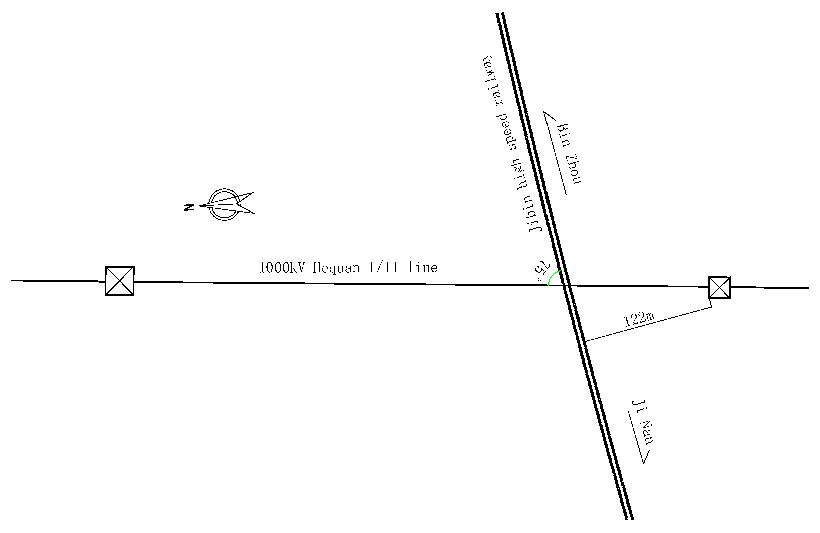
For the 1000 kV Hequan I/II line, the power line is a double 1000 kV, the crossing point of the power line from the top of the track is 25.75 m (according to the maximum arc sag of the conductor operating temperature 40 °C case), the north side of the tower is 113.2 m high, the outer edge of the tower to the center of the track is about 374 m, the south side of the tower is 98.8 m high, the outer edge of the tower to the center of the track is about 122 m, the angle of intersection of the power line and the railroad is about 75 degrees. Across the stall does not meet with the independent tension-resistant section, and the wire joints from the north side of the tower have a horizontal distance of 213 m across the section of the insulator string using a double “I” string type; a section of the plan schematic diagram is shown in Figure 1.
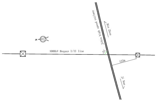
Figure 1.
Plan of the intersection of the 1000 KV UHV transmission line and railway.
2. Study of the Scope of High-Speed Rail Protection and Line-Break Load
2.1. Study of the Scope of Protection of High-Speed Rail
According to potential accidents involving UHV transmission lines, two main working conditions are to be considered for the protection of high-speed railways: the downed tower working condition and the broken line working condition.
The relevant provisions of transmission tower load design in the national standards are the “Design Code for 1000 kV Overhead Transmission Lines” GB 50665-2011, the “Design Code for ±800 kV DC Overhead Transmission Lines” GB 50790-2013 (2019 version), and the “Technical Regulations for Design of Ultra-high Voltage Overhead Transmission Line Tower Structures” DL/T5486-2013 [5,6,7]. In the design of transmission lines, the safety factor of the pylon is extremely high, especially for a 1000 kV UHV pylon. Therefore, the probability of a tower collapse accident is extremely low, and only a wire break accident needs to be considered in the design of the underground railway.
The calculation of the break line (including longitudinal unbalanced tension) of the overhanging type of tower is carried out under meteorological conditions of −5 °C, with ice and no wind. According to the industry standard “Overhead Transmission Line without Spanning Frame Construction Process Guidelines” DL/T5301-2013 [8] and the national standard “1000 kV Overhead Transmission Line Design Specification” GB50665-2011, the protection length for a 1000 kV transmission line in case of conductor breakage impact is calculated using the following formula:
where: B—Seal net width; Zx—10 m/s-Wind deflection distance at intersections under meteorological conditions; b—Maximum horizontal spacing of bundled conductors; m—Horizontal distance of crossings from neighboring pylons; l—Horizontal straight line distance between two adjacent towers; H—horizontal tension of conductor operation; λ—the length of the pendant insulator string; W—Weight per unit length of wire; d—Outer diameter of wire; k—Wind carrier type coefficient; n—Horizontal width of track; α—Crossing angle; hw—Vertical height between wire and crossed object; K—Safety coefficient, take 1.5; L—Protection length.
Using the relevant values, it can be calculated that the length of the protective section required for the HSR is not less than 138.5 m.
2.2. Study of Impact Loads on Transmission Line Breaks
To study the loads caused by transmission line breaks, the transmission line breaks are first dynamically analyzed. The power conductor is considered a cable unit, and the deformation property of the cable unit consists of two parts: tension and bending of the axis.
where: E denotes the cable material tensile modulus of elasticity; A represents the tensile section area; I denotes the moment of inertia; k represents the bending deformation length; l represents the length of the deformed part.
The tensile section variable, the bending deformation length, is expressed in r vector coordinates as follows:
The kinetic equation of the unit is:
where represents the generalized elastic force of the unit, and represents the external force applied to the unit, including generalized gravity, contact force, and other forms of external loads. When the wire is in sliding contact with the protective structure, the constraint relationship needs to be described using nonlinear constraints. The set of kinetic equations is obtained as a set of second-order differential-algebraic equations.
where: C denotes the system constraint equation; Ce represents the Jacobi matrix obtained by partially differentiating the constraint equation with respect to the node coordinates; λ is the Lagrange multiplier. The commonly used methods for solving this equation include the Newmark method, the HHT method, the generalized α method, etc. [2].
The model is based on dynamic equations and numerical analysis. The analysis is conducted under two operating conditions: conductor fracture and in-span conductor joint fracture. The unbroken end of the conductor is controlled by a hinged support, while the broken end is entirely freed, and the bottom of the high-speed rail (HSR) protection construction is completely secure. Figure 2 shows the calculation model 2.
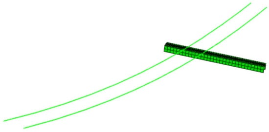
Figure 2.
Computation model.
Working Condition 1: Wire breakage after calculation, the changes in wire drop, the protective structure impact force, and structural stress are shown in Figure 3, Figure 4 and Figure 5:
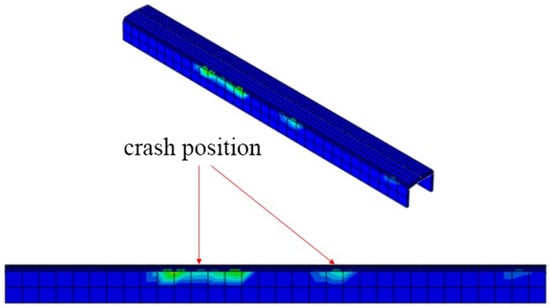
Figure 3.
Calculation results of impact structures on transmission lines.
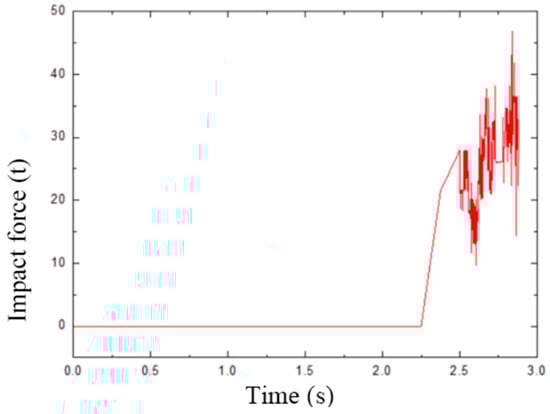
Figure 4.
Time evolution curve of transmission line impact force.

Figure 5.
Time evolution curve of structural stress.
The mathematical results show that before the wire makes contact with the structure, the impact force is zero. The impact force is 21.48 tons when the object first makes contact with the structure at 2.37 s. As a result, the wire and the structure clash several times until reaching a maximum impact force of 46.92 tons at 2.84 s. The impact force reduces with time. Before the wire makes contact with the structure, the stress is around zero MPa. The structural stress is 0.03 MPa when the wire makes contact with the structure at 2.37 s. As the wire continually collides with the framework, the structural stress grows until it reaches a high of 0.73 MPa at 2.84 s.
Working Condition 2: Fracture of wire joints within the span.
In this scenario, the in-span conductor connector fails and comes into contact with the structure. The impact will be greater than that in Case I.
After calculation, the impact force and structural stress changes of the falling conductor and protective structure are shown in Figure 6, Figure 7 and Figure 8:
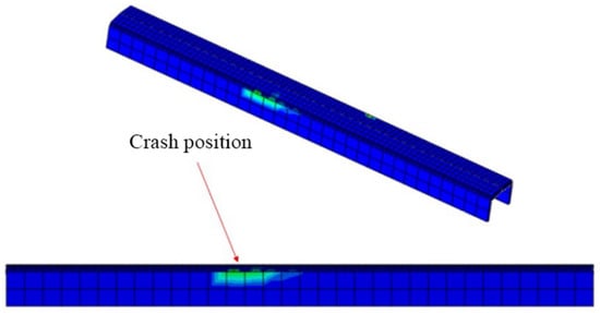
Figure 6.
Calculation results of impact structures on transmission lines.
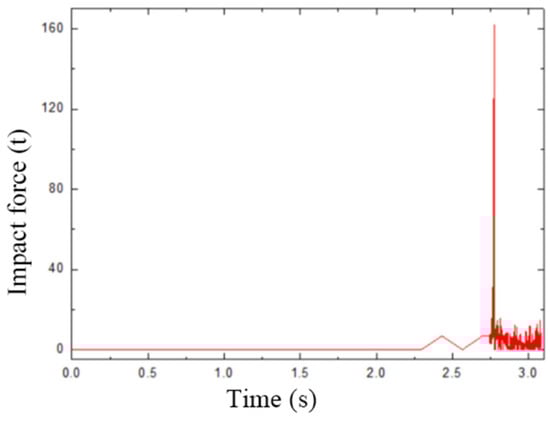
Figure 7.
Time evolution curve of transmission line impact force.
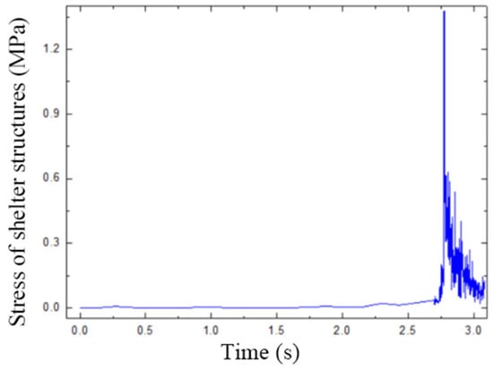
Figure 8.
Time evolution curve of structural stress.
From the calculation results, it can be observed that prior to the wire contacting the structure, the impact force is 0. Upon initial contact with the structure at 2.73 s, the impact force is 16.5 tons. Subsequently, as the wire and the structure collide repeatedly, at 2.77 s, the maximum impact force recorded is 94.86 tons. As time passes, the impact force gradually diminishes. Before the wire makes contact with the structure, the stress in the structure is almost 0 MPa. When the wire first makes contact with the structure at 2.73 s, the structural stress is 0.23 MPa. Subsequently, as the wire repeatedly collides with the structure, the structural stress increases to a maximum value of 1.37 MPa at 2.77 s. The comparison of the two conditions reveals that the maximum values of the impact force and structural stress occur when the wire joint fractures within the span. Referring to the “Code for the Design of Concrete Structures” (GB 50010-2010), the standard compressive strength of C35 concrete is 23.4 MPa, and the standard tensile strength is 2.20 MPa. The design compressive strength of C35 concrete is 16.7 MPa, and the design tensile strength is 1.57 MPa. The maximum stress in the structure is smaller than the design value of tensile strength, indicating that the reinforced concrete structure using C35 can meet the safety requirements under all working conditions [9,10].
3. Study of the Form of Protective Structures and Construction Measures
3.1. Study of the Design of Protective Structures for High-Speed Rail
Currently, the protection shed hole serves as the primary protective construction for high-speed railways. Rigid and flexible shelters are the two types of protective shelter structures.
A rigid shelter’s major component is its reinforced concrete frame, which is occasionally topped with a layer of cushioning material above the frame’s top plate. Examples of this type of material include gravel, clay, or the more recent sand-expandable polyethylene (EPE) composite cushion. By successfully preventing structural damage or deformation brought on by the impact of external foreign objects, these cushions help safeguard the security of high-speed railway operations. This shape is frequently referred to as a classic cushion. The structure of a flexible shelter consists of replacing the rigid shelter’s ceiling plate with metal flexible mesh. Additional features include anchor ropes, steel columns, and energy-dissipating sections. The components are assembled using a specific method. The flexible shed hole is increasingly in use because it uses a lot less energy than the rigid shed hole, is less expensive to build and maintain, and is better for the environment [11,12].
Considering the conductivity of the metal material and the interactions between the special environment and the ultra-high voltage transmission line, this design takes into account the use of the reinforced concrete shed hole structural form. The project crosses the 1000 KV ultra-high voltage transmission line, and it is relatively close to the transmission line discharge safety zone.
With reference to the high-speed railway tunnel’s shed hole design for protecting against dangerous rockfalls and the overall reinforced concrete structure, there are three types of shed holes: (1) Using a beam-slab-column structural design, creating a concrete frame, and placing an independent foundation beneath the column. (2) To lessen the high-speed rail’s aerodynamic effect, a piece of the wall on both sides should have windows that open periodically. The structural form of this section should resemble that of an elongated open hole. The straight wall’s arch structure should also be used. (3) Under limited NAC circumstances, a straight-wall, flat-roofed building with windows on both sides of the wall should be used [13,14,15,16,17]. The three schemes’ engineering schematic diagrams are displayed in Figure 9, Figure 10 and Figure 11.

Figure 9.
Beam-slab-column structural form.
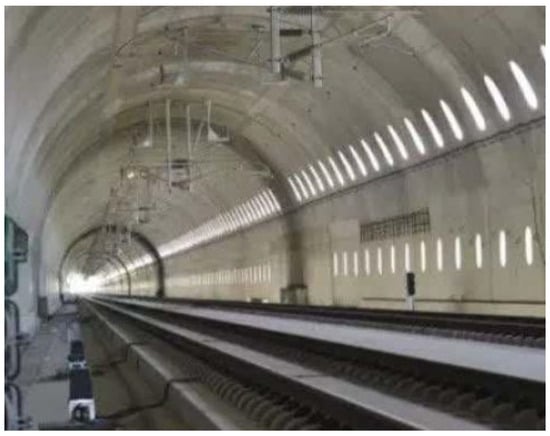
Figure 10.
Straight wall arch structural form.

Figure 11.
Straight wall flat top structural form.
Through a comprehensive analysis of the three options based on structural form, dimensions, transmission, construction conditions, etc., the straight-wall flat-roof structure is recommended as the optimal structural option, as illustrated in Table 1.

Table 1.
Programme Comparison Table.
C35 concrete is used in the straight-wall flat-roof structure, and the thickness of the wall and roof is 1 m. The base plate adopts a pile foundation with a diameter of 1 m, and the length of the pile is 18 m. The steel bar is a HRB400, φ25@100. The calculation results under fundamental combination, nominal combination, and accidental combination are shown in Table 2.
Table 2.
Structural calculation results.
3.2. Study of Construction Measures for Protective Structures
The primary risk factor for the construction of 1000 KV ultra-high-voltage power protection sheds, caves, and related projects is when the distance between construction machinery and power lines is less than the safety distance. This situation can result in induced voltage being generated by the construction equipment, posing a threat to the safety of construction personnel.
According to the safety notice issued by the State Grid Shandong Power Company regarding the construction of protective shelter holes for the Jinwei High-speed Railway Jinan Liaison Line (Jibin High-speed Railway) under the 1000 kV Hequan I/II Line #303–#304, special vehicles such as cranes, transporters, and large-scale machinery involved in construction work under the 1000 kV power line and within the protection zone must maintain a safety distance of more than 16 m from the electrically charged equipment (conductors, fittings, etc.). The protection zone is defined as the area under the conductor and the conductor sideline extending outward, within the two planes formed by the conductor line and the sideline of the conductor line extending horizontally for 30 m and perpendicular to the ground.
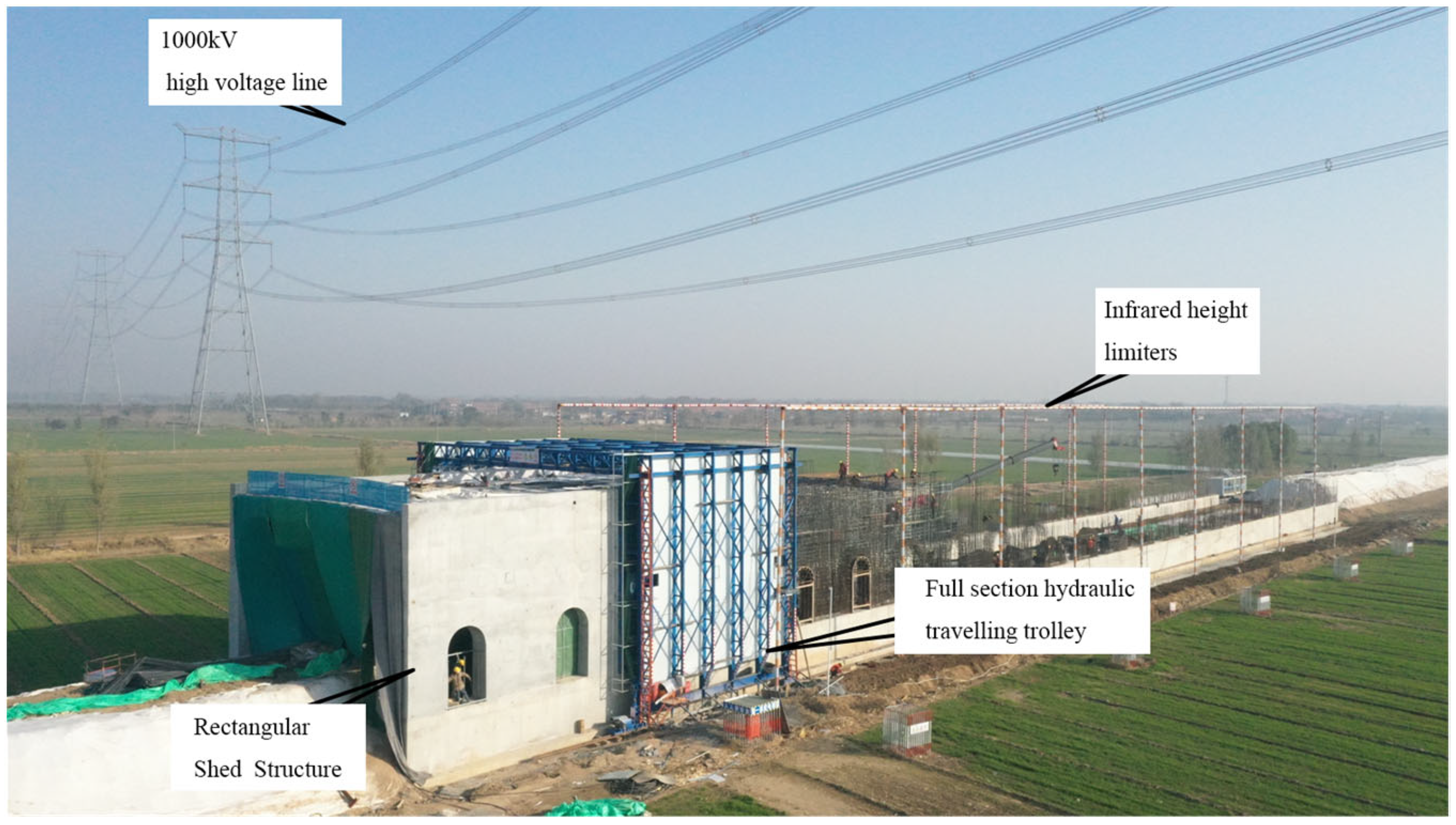
Combined with on-site measurements and calculations, the top of the shed structure is only 2 m away from the safety control line, and the nearest point is only 1.5 m. Therefore, it is not feasible to use large cranes for lifting materials and pouring concrete. Due to the proximity to the safety control line, high-altitude protection measures must be implemented to prevent construction personnel and materials from mistakenly entering the protection zone, which could result in safety accidents. In response to the aforementioned points, construction measures such as establishing automatic warning protection corridors and implementing overall movable cart molding were adopted following the study. These measures effectively addressed construction near the safety zone and helped prevent safety accidents. The automatic warning protection corridor involves installing height limiters on the right and left sides before and after the construction area of the shed structure. The height limiters are made of φ180 steel pipes, and their bottoms are connected to the original ground. Grounding measures are implemented to prevent induced electric currents. The infrared alarm device is installed at the top of the height limiters, where the infrared rays create a dense network, reducing inductive currents and enabling automatic warnings for objects exceeding the limit. As shown in Figure 12.
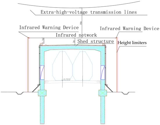
Figure 12.
Schematic diagram of the protection corridor.
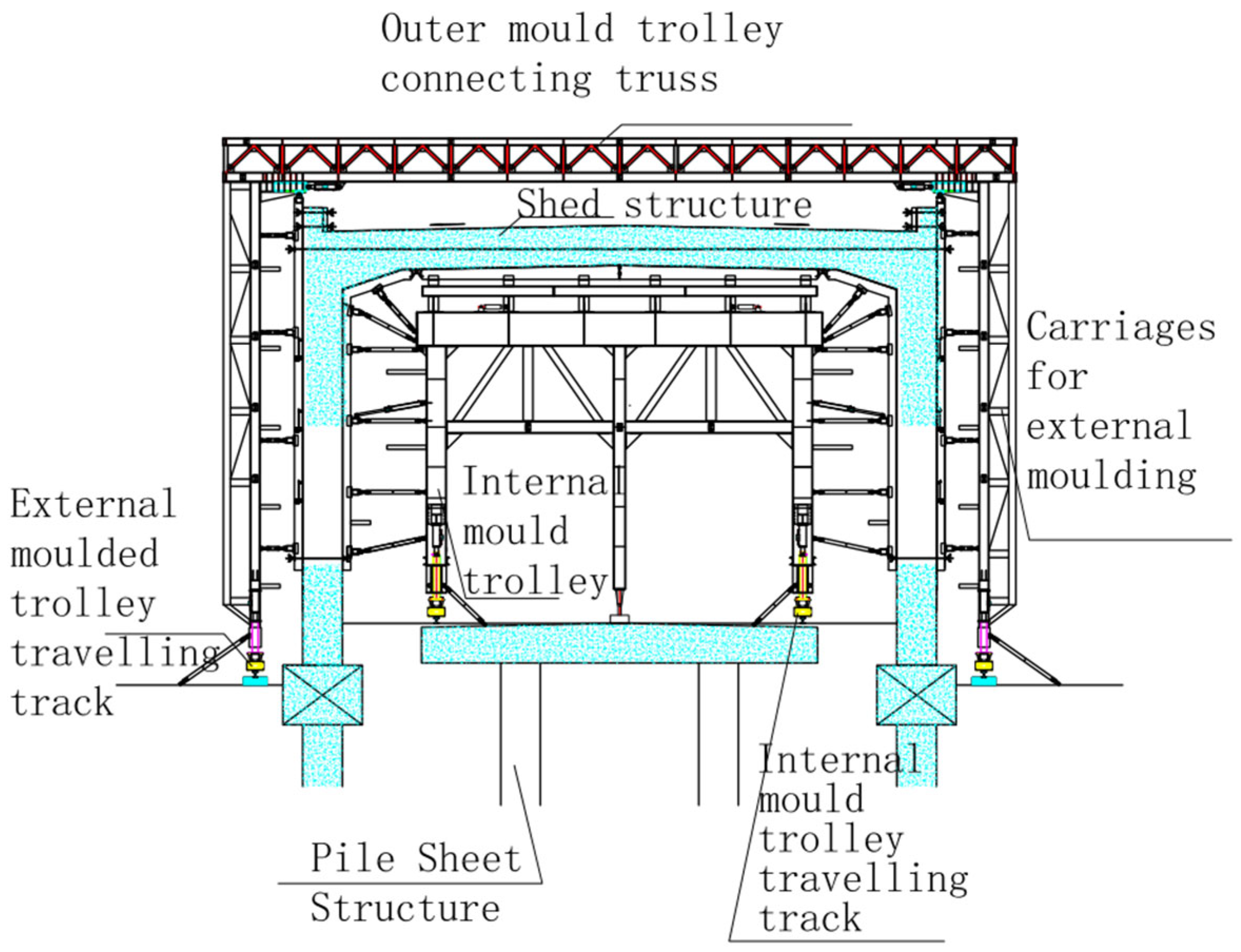
Due to the proximity of the top of the shed cavern structure to the safety control line, the pouring of concrete in the shed cavern cannot be accomplished using a traditional stent pump truck. To solve the problem, a movable integral cart is adopted, with steel mold plates placed inside and outside, and local windows on the mold plates for concrete pouring and vibration [18,19,20]. The construction process is as follows: construction preparation → measurement and sampling → steel formwork cart installation in place → wall and roof reinforcement installation → outside truss formwork installation in place → concrete pouring → dismantling and maintenance → automatic traveling of formwork cart to the next section → construction of the next section. The structure of the steel formwork cart is shown in Figure 13.
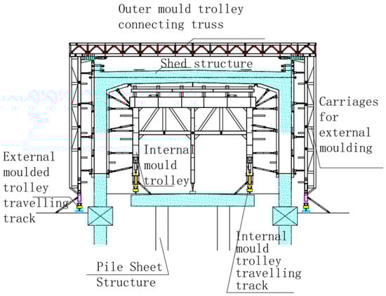
Figure 13.
Moving steel mold trolley.
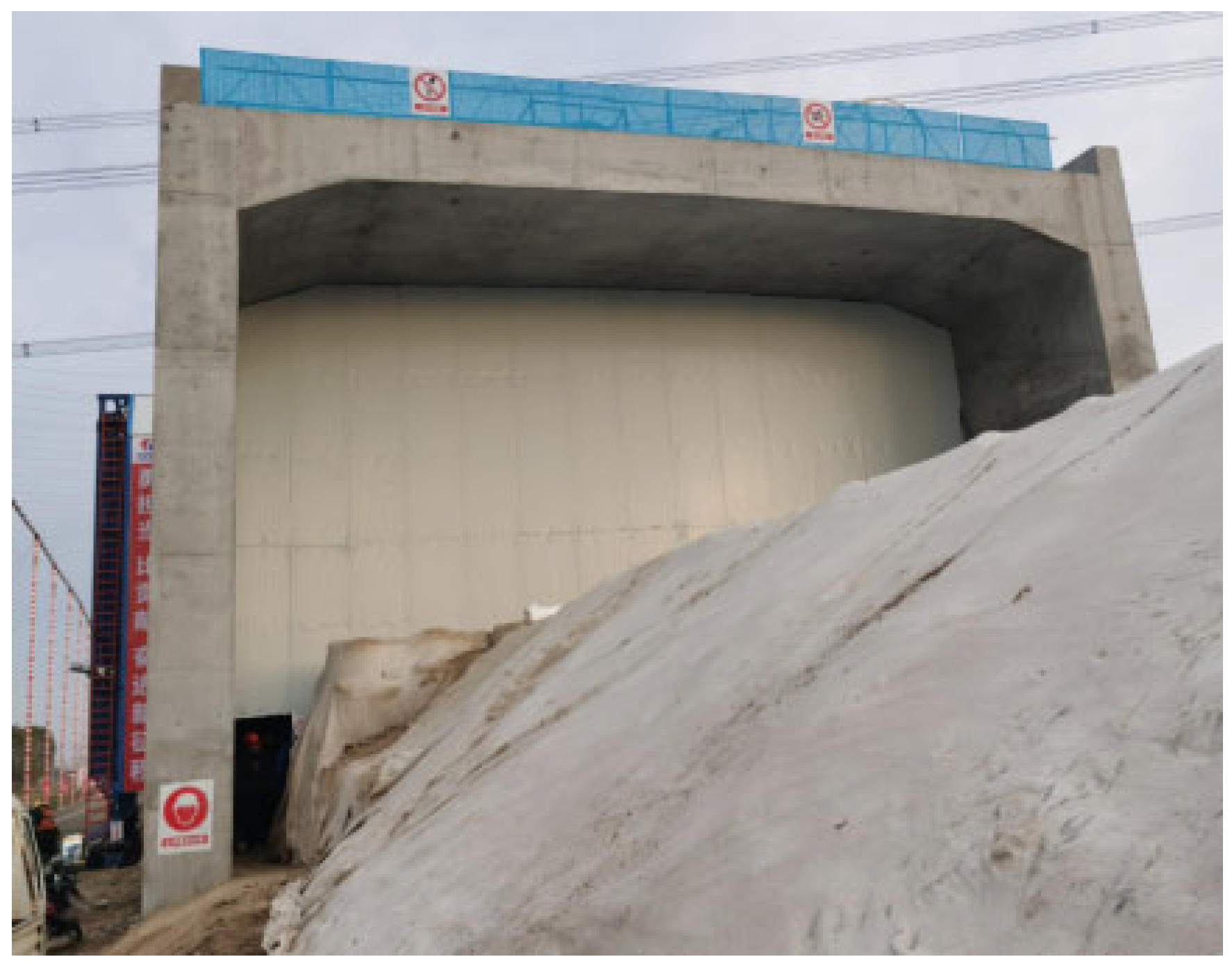
From the field implementation perspective, the adoption of a structural design featuring a straight wall, a flat roof with windows on both sides, and the use of an infrared height-limiting frame and a movable cart for casting concrete during construction have ensured the safe and efficient construction of high-speed rail protection sheds under extra-high-voltage transmission lines. Field implementation has yielded positive results. Figure 14 shows a photo of the protective shed tunnel site.
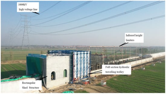
Figure 14.
Site of protective shed tunnel.
4. Conclusions
Through research into the protection scheme for high-speed railways near 1000 KV ultra-high-voltage transmission lines, an equation of motion for the disconnected line, a calculation model, and other parameters were established to determine the load and protection range of the disconnected line. By integrating common high-speed railway protection structures such as sheds and openings, a protection structure design was proposed involving a straight wall with a flat roof and a side wall with open windows near the safety zone of the ultra-high-voltage transmission line. Additionally, the construction method for an automatic early-warning protection corridor and a fully movable cart molding was developed and successfully applied. The study draws the following conclusions:
- (1)
- During the design of the UHV transmission line, the safety factor of the tower is set to be extremely high. Therefore, the protection of the high-speed rail under the 1000 KV UHV line primarily emphasizes safeguarding against line-break accidents in extreme conditions.
- (2)
- The structural form of the C35-reinforced concrete shed hole can not only meet the force requirements under disconnected conditions but also reduce the mutual influence with the UHV transmission line.
- (3)
- The structural form of a straight wall, flat roof, and side wall window can also prevent the structure from intruding into the safety control area of the transmission line while meeting the headroom requirement.
- (4)
- The construction measures, such as establishing an automatic warning protection corridor and utilizing an overall movable cart molding, can guarantee the safe and efficient construction of the high-speed rail protection shelter structure within the safety zone of the adjacent ultra-high-voltage transmission line. The implementation has shown positive results.
Author Contributions
Conceptualization, W.X. and Y.S.; methodology, software, validation, Y.S. and W.X.; formal analysis, Y.S.; data curation, writing—original draft preparation, Y.S.; writing—review and editing, visualization, W.X.; funding acquisition, W.X. All authors have read and agreed to the published version of the manuscript.
Funding
This research was funded by the Natural Science Basic Research Program of Shaanxi Province (Grant No. 2022JQ-277) and The Central Special Fund for scientific research in colleges and universities (No. 300102282110).
Data Availability Statement
Data is provided within the manuscript.
Conflicts of Interest
The authors declare no conflict of interest.
References
- Zhou, Y.; Chen, J.; Zhang, L.; Zhang, Y.; Teng, C.; Huang, X. Opportunity for developing ultra-high voltage transmission technology under the emission peak, carbon neutrality, and new infrastructure. High Volt. Eng. 2021, 47, 2396–2408. [Google Scholar]
- Li, X. New infrastructure construction and policy orientation for a smart society. Reform 2020, 5, 34–48. [Google Scholar]
- Sun, J.; Jiang, Z.; Yang, J.; Zheng, L.; Zhao, P.F.; Mu, Q.; Cong, X. Research on the line-break influence range of power line crossing electrified railway. China Railw. 2023, 9, 117–124. [Google Scholar] [CrossRef]
- Liu, B. Discussion on the scheme of adding protective sheds to the corridor of the new railway crossing the UHV transmission line. Electr. Railw. 2019, 30, 72–76. [Google Scholar]
- GB 50665-2011; Code for Design of 1000kV Overhead Transmission Line. China Planning Press: Beijing, China, 2011.
- GB 50790-2013; Code for Designing of ±800kV DC Overhead Transmission Line. China Planning Press: Beijing, China, 2019.
- DL/T5486-2020; Technical Specification for the Design of Steel Supporting Structures of Overhead Transmission Line. China Planning Press: Beijing, China, 2020.
- DL/T5301-2013; Construction Technology Guide for Tension Stringing of Overhead Transmission Line When Over-Crossing Live Lines without Cross Frame. China Electric Power Press: Beijing, China, 2014.
- GB 50010-2010; Code for Design of Concrete Structures. China Architecture Publishing & Media Co., Ltd.: Beijing, China, 2015.
- Mo, Z.-L.; Zhang, Z.-F.; Hu, G.-Y. Experimental Research for Broken Conductor Wire of ±800 kV DC EHV Suspension Tower Model. Electr. Power Constr. 2010, 31, 30–33. [Google Scholar]
- He, S.-M.; Shen, J.; Wu, Y. Rock shed dynamic response to impact of rock-fall. Rock Soil Mech. 2011, 32, 781–787. [Google Scholar]
- Jiang, J.; Yang, X.; Luo, Y.; Zhou, Y. Summarize about traditional shed hole compared with flexible shed hole in application research. Build. Struct. 2016, 46 (Suppl. S1), 249–252. [Google Scholar]
- Jiang, D.; Zhou, X.; Tang, J.; Liu, K. Mechanical response of large span arched open cut tunnel structure under rockfall impaction. Railw. Stand. Des. 2021, 65, 122–127. [Google Scholar]
- Wang, Y.; Li, S.; Li, W.; Tan, J.; Guo, Z. Study on the Characteristics and Protection Design of Tuyu Tunnel Rockfall on Zhangjiajie-Jishou-Huaihua Railway. Railw. Stand. Des. 2023, 67, 126–133. [Google Scholar]
- Wen, X.; Pei, X.; Pei, Z.; Yang, H.; Chen, Z.; Zhang, Y. Study on structural design and safety of shed tunnels in the scenic area of Changbai mountains. Mod. Tunn. Technol. 2021, 58, 151–157. [Google Scholar]
- Yang, C. Study on protection scheme of dangerous rock falling on high steep slope of chizhou-huangshan high speed railway tunnel. Railw. Eng. 2023, 63, 124–126. [Google Scholar]
- Wang, K.; Gao, C.; Zhou, Y. Research on Design of Railway Bridge-shed Integrated Structure for Preventing Falling Rocks. Railw. Stand. Des. 2023, 67, 106–112+154. [Google Scholar]
- Li, X.; Lin, C.; Li, J. New Construction Method for Secondary Lining of Railway Tunnel and Design of Lining Trolley Scheme. Tunn. Constr. 2021, 41, 293. [Google Scholar]
- Zhang, M.; Jia, D.; Wang, S.; Gao, C. New Automatic Pouring and Vibrating Techniques for the Construction of Railway Tunnel Lining. Mod. Tunn. Technol. 2022, 59, 29–34+41. [Google Scholar]
- Zhang, H. Research on rapid construction technology for arch wall lining inopen-cut hole of large-section loess tunnel. Railw. Constr. Technol. 2020, 1, 93–96. [Google Scholar] [CrossRef]


Disclaimer/Publisher’s Note: The statements, opinions and data contained in all publications are solely those of the individual author(s) and contributor(s) and not of MDPI and/or the editor(s). MDPI and/or the editor(s) disclaim responsibility for any injury to people or property resulting from any ideas, methods, instructions or products referred to in the content. |
© 2024 by the authors. Licensee MDPI, Basel, Switzerland. This article is an open access article distributed under the terms and conditions of the Creative Commons Attribution (CC BY) license (https://creativecommons.org/licenses/by/4.0/).