Article

Using Fractal Calculus to Solve Fractal Navier–Stokes Equations, and Simulation of Laminar Static Mixing in COMSOL Multiphysics

1
Physics and Accelerators Research School, Nuclear Science and Technology Research Institute, Tehran 14395-836, Iran
2
Department of Mathematical Sciences, Faculty of Science and Technology, Universiti Kebangsaan Malaysia, Bangi 43600, Malaysia
*
Author to whom correspondence should be addressed.
Fractal Fract. 2021, 5(1), 16; https://doi.org/10.3390/fractalfract5010016
Submission received: 21 December 2020 / Revised: 16 January 2021 / Accepted: 29 January 2021 / Published: 8 February 2021

Abstract

:
Navier–Stokes equations describe the laminar flow of incompressible fluids. In most cases, one prefers to solve either these equations numerically, or the physical conditions of solving the problem are considered more straightforward than the real situation. In this paper, the Navier–Stokes equations are solved analytically and numerically for specific physical conditions. Using F α -calculus, the fractal form of Navier–Stokes equations, which describes the laminar flow of incompressible fluids, has been solved analytically for two groups of general solutions. In the analytical section, for just “the single-phase fluid” analytical answers are obtained in a two-dimensional situation. However, in the numerical part, we simulate two fluids’ flow (liquid–liquid) in a three-dimensional case through several fractal structures and the sides of several fractal structures. Static mixers can be used to mix two fluids. These static mixers can be fractal in shape. The Sierpinski triangle, the Sierpinski carpet, and the circular fractal pattern have the static mixer’s role in our simulations. We apply these structures just in zero, first and second iterations. Using the COMSOL software, these equations for “fractal mixing” were solved numerically. For this purpose, fractal structures act as a barrier, and one can handle different types of their corresponding simulations. In COMSOL software, after the execution, we verify the defining model. We may present speed, pressure, and concentration distributions before and after passing fluids through or out of the fractal structure. The parameter for analyzing the quality of fractal mixing is the Coefficient of Variation (CoV).

1. Introduction

One of the main problems in classical calculus is that the function is discontinuous, or its derivative does not exist at some points. Fractals, on the other hand, are inherently defined as discontinuous sets and nowhere or somewhere differentiable [1,2]. The undeniable fact is that classical continuum mechanics is not capable of describing fluid mixtures or multi-phase problems. Its reason is that classical mechanics is a local theory in which partial derivatives exist. They have no solution for discontinuous points. The fractional calculus came to their aid as the non-local theory. Several fractional models have been introduced by researchers following this approach, for instance [3,4,5,6]. In other words, many believe that substituting a non-local theory instead of a local theory is the only solution. However, in their papers, Parvate and Gangal [7,8,9] introduce another approach based on the local theory entitled F α -calculus, which is convenient for discontinuous point and even non-differentiable continuous functions.

1.1. Fractal Calculus

In fractals, irregularity and non-smoothness are the characteristics for which there is no way to define differential mathematical structures with ordinary calculus. Fortunately, this has been made possible by the introduction of the fractal calculus [7,8,9]. This formulation’s suitability on fractal sets, and curves was proved by using the fractal calculus to solve the Fokker-Planck and Langwin equations [10,11].
For the fractal pattern “Cantor tartan spaces”, Golmankhaneh, and Fernandez, by using of F α -calculus, define integrals and derivatives of functions on them with their related differential equations [12]. Cantor sets are of type “totally disconnected set.” Sub- and super- diffusion on Cantor sets appear when one needs to relax the continuum requirement [13].
In [7,8], F α -calculus is firstly formulated based on fractal subsets of the real line. Main definitions involves an integral of order α , 0 < α < 1 , called F α -integral and a derivative of order α , 0 < α < 1 , called F α -derivative. This concept enables us to differentiate functions, like the Cantor staircase, “changing” only on a fractal set. The F α -derivative is local, unlike the classical fractional derivative, which is of type non-local. They secondly generalize their work in R n [9]. This generalization from R to R n is called F α -calculus on fractal curves, such as the von Koch curve. Integration and differentiation in F α -calculus are of type Riemann-like where α is the dimension of F. In the last decade, F α -calculus has been utilized in science and engineering [12,14,15,16,17,18,19,20,21,22].
Definition 1
([7]). If F is an α-perfect set and 0 < α < 1 then the F α -derivative of f at x is
D F α ( f ( x ) ) = F lim y x f ( y ) f ( x ) S F α ( y ) S F α ( x ) i f x F 0 othervise ,
if limit exist. The α-perfect sets are sets having properties necessary to define F α -derivative.
Like the first order derivative, the F α -derivative is a limit of a quotient. But here the limit is F-limit, and the denominator is the difference in the values of the staircase function S F α at two points. Moreover, intuitively speaking, F is typically the set of change of the function, and α is typically the γ -dimension of F.

1.2. Static Mixers

One of the problems we encounter in mixing two fluids is the turbulence phenomenon, which is a consequence of using the engine. The fractal mixing is the new method that is predictable because of its symmetry. This method prevents the flow of turbulence [23]. Studying and design of suitable fractal mixer and the fractal reactor can increase the quality of mixing. We can see the importance of this issue in various fluid mechanical engineering issues.
Static mixers, which are also known as motionless mixers, have become standard in the process industries. The use of static mixers in continuous processes is a good alternative to conventional agitation because one can achieve similar and sometimes better performance at a lower cost. To name the potential advantages of static mixer, we may refer to small space requirements, low equipment cost, no power required except pumping, and no moving parts except the pump.
Static mixers are also referred to by other similar names, such as a motionless mixer or in-line mixer [24,25,26,27,28,29,30,31,32,33]. The fluid is pumped through a tube with a defined cross-section and passes through a fractal mixer. This type of mixing technique is suitable for slow flow. In this case, the pressure drop is low compared to the turbulent flow.
The prototype design of a static mixer is made of a series of identical, motionless inserts named “elements”, which can be installed in pipes, columns, or reactors. The reason for using of elements is to redistribute fluid in the directions transverse to the main flow, which may be in the radial or tangential directions. Nowadays, static mixers are commonly used in chemical and petrochemical industries to perform continuous operations. In laminar flows, static mixers divide and sequentially redistribute streamlines using only the flowing fluid’s energy. The various types of static mixers behave quite differently, and classification schemes have been introduced to explain these differences based on mixing elements’ geometry [34,35,36].
This article consists of two independent sections: analytic section and simulation. In the analytical part, the problem is solved in two dimensions, while in the simulation part, the problem is in three dimensions. We first solve fractal form of Navier–Stokes equations which are momentum equations and continuity equation in two dimensions in cartesian coordinates for laminar incompressible fluids. Using COMSOL software, then we present the model studies that mix a type of fluid with water, which is called diluting the fluid at room temperature. Three kinds of fractal grids do this mixing. We consider three families of fractal space-filling grids with triangles, squares, and circles, respectively.

2. Main Results

The method used by Yang et al. [37] to solve Navier–Stokes equations is different from our work in this paper, which is based on fractal calculus introduced by Parvate and Gangal [7,8,9]. We start with Navier-stokes equations in two dimensions in cartesian coordinates for laminar incompressible fluids [38,39]. The momentum components of equations in fractal space can be expressed as follows:
u ( x , y ) x D ξ α u ( x , y ) + v ( x , y ) x D ξ α u ( x , y ) = ( 1 ρ ) x D ξ α P ( x , y ) + ν [ ( x D ξ α ) 2 u ( x , y ) + ( y D ξ α ) 2 u ( x , y ) ] .
u ( x , y ) x D ξ α u ( x , y ) + v ( x , y ) x D ξ α v ( x , y ) = ( 1 ρ ) x D ξ α P ( x , y ) + ν [ ( x D ξ α ) 2 v ( x , y ) + ( y D ξ α ) 2 v ( x , y ) ] .
All fractal derivatives in Equations (2) and (3) are of type local.
The continuity equation is also the third relation that connects the derivatives of the velocity components in the fractal space.
x D ξ α u ( x , y ) + y D ξ α v ( x , y ) = 0 .
To solve the above differential equations, we use the concept of floating function in which we assume functions u and v can be written as follows:
u = u ( f ( S F α ( x ) , S F α ( y ) ) ) , v = v ( f ( S F α ( x ) , S F α ( y ) ) ) .
Using Equation (5), the Equation (4) is written as follows:
( f D ξ α u ) ( x D ξ α f ) + ( f D ξ α v ) ( y D ξ α f ) = 0 .
By restricting equation
γ ( x D ξ α f ) = β ( y D ξ α f ) .
We obtain
β ( f D ξ α u ) + γ ( f D ξ α v ) = 0 .
or
β u ( f ) + γ v ( f ) = c .
The solution of Equation (7) is
f = f ( β S F α ( x ) + γ S F α ( y ) ) .
From Equations (8) and (9) we have
x D α v = ( β γ ) x D α u ,
and
( x D α ) ( x D α v ) = ( β γ ) ( x D α ) ( x D α u ) .
Substituting Equation (11) into Equation (3) led to
u ( x D α u ) + v ( y D α u ) = γ β ( 1 ρ ) ( y D α P ( x , y ) ) + ν [ ( x D α ) 2 u + ( y D α ) 2 u ] .
Now we subtract Equation (2) from Equations (11) and (12)
1 ρ [ β ( x D α P ( x , y ) ) + γ ( y D α P ( x , y ) ) ] = 0 .
The general solution of this equation is P = P ( γ S F α ( x ) β S F α ( y ) ) . Now we rewrite Equation (2) as follows
u ( x D α u ) + v ( y D α u ) = ( γ β ) ( 1 ρ ) ( y D α P ( x , y ) ) ν [ ( x D α ) 2 u + ( y D α ) 2 u ] = ( 1 ρ ) ( x D α ) P ( x , y ) .
Equation (2) can be written as
u ( x D α u ) + v ( y D α u ) = ν [ ( x D α ) 2 u + ( y D α ) 2 u ] .
Since u = u ( f )
x D α u = [ x D α f ] [ f D α u ] , y D α u = [ y D α f ] [ f D α u ] .
We have
( x D α ) 2 u = [ ( f D α ) 2 u ] [ x D α f ] 2 + [ ( x D α ) 2 f ] [ f D α u ] .
and
( y D α ) 2 u = [ ( f D α ) 2 u ] [ y D α f ] 2 + [ ( y D α ) 2 f ] [ f D α u ] .
From Equations (7), (9), (18), and (19) the following equation is deduced:
c γ [ ( f D α ) u ] [ y D α f ] = ν { ( f D α ) ( f D α u ) { [ x D α f ] 2 + [ y D α f ] 2 } + f D α u [ [ x D α ] [ x D α f ] + [ y D α ] [ y D α f ] ] } .
For f = β S F α ( x ) + γ S F α ( y )
c ν ( β 2 + γ 2 ) ( [ ( f D α ) ] [ ( f D α ) u ] = u .
u = A exp ( c ν ( β 2 + γ 2 ) ( β S F α ( x ) + γ S F α ( y ) ) ) + B .
v ( f ) = 1 γ ( c β B β A exp ( c ν ( β 2 + γ 2 ) ( β S F α ( x ) + γ S F α ( y ) ) .
The graphs of the functions u and v have been given in Figure 1 and Figure 2.
For f = e ( β S F α ( x ) + γ S F α ( y ) )
( x D α ) f = β f , ( x D α ) ( x D α ) f = β 2 f , ( y D α ) f = β f , ( y D α ) ( y D α ) f = β 2 f .
[ c ν ( β 2 + γ 2 ) 1 ] ( [ ( f D α ) u ] ) = f [ ( f D α ) ] [ ( f D α ) u ] .
u = A + B ( β S F α ( x ) + γ S F α ( y ) ) c ν ( β 2 + γ 2 ) .
v = c β A γ β ( β S F α ( x ) + γ S F α ( y ) ) c ν ( β 2 + γ 2 ) .
The graphs of the functions u and v have been given in Figure 3 and Figure 4.

3. To Model Diluting the Fluid with Fractal Mixing Patterns

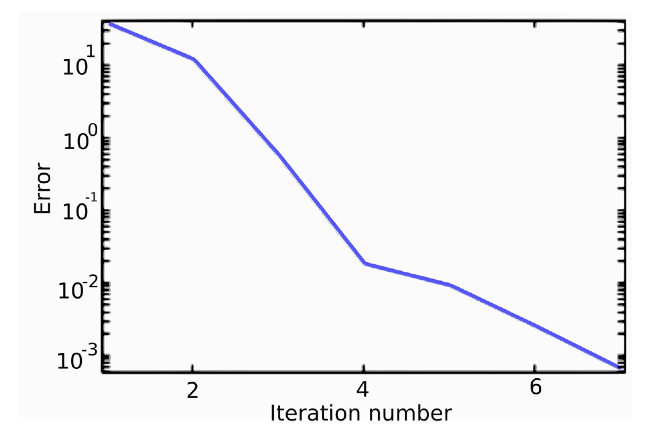
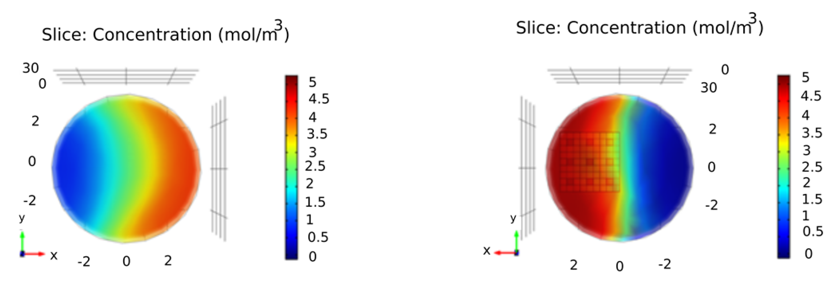
We do our simulation in COMSOL Multi-physics software. Many electrical, mechanical, fluid, and chemical simulations have been made by using COMSOL. Its name is ”Multi-physics” because all relevant physical effects can be included and coupled in this software. Fortunately, all industries benefit from Multiphysics simulations. COMSOL helps one to be familiar with a complete simulation environment. Virtual testing is much faster than testing physical prototypes. Laminar flow interface and Diluted species interface are two of the many interfaces which can be seen and used in COMSOL. All problems can be considered by the numerical method called the Finite Element Method (FEM) in the branch of numerical analysis. The FEM is widely used as a numerical method for the solution of PDE problems. The implementation of FEM usually follows a standard step-by-step procedure that is started with ”discretization” and then ”element equations”. In COMSOL, it is possible to calculate and draw convergence diagrams in order to show the error approximation, an example is given in Figure 5. The calculation time for this case was 28 s. After the execution, we verify the defining model. We may present speed (Figure 6), pressure, and concentration distributions (Figure 7) before and after passing fluids through or out of the fractal structure. We chose COMSOL for our work because one could do mathematical modeling and physical modeling together. In the geometry section, the fractal configurations with fractal circular can be made in the model builder (Figure 8). So, we can set up our model, optimize design, and even share it as a simulation application.
The present model studies the mixing of a type of fluid with water, which is called diluting the fluid at room temperature. For this purpose, two interfaces must be used to simulate the problem. 1—Laminar flow interface and 2—Diluted species interface.

4. Results and Discussion

The quality of mixing two fluids in a pipe or channel can be statistically expressed by the Coefficient of Variation (CoV) parameter, which is defined as follows:
C o V = i = 1 N ( c c i 1 ) 2 N 1 · 1 c m e a n = σ c m e a n .
The values c is the measured average concentration of the additive, c m e a n is the value of the average theoretical concentration, c i is the local concentration of the additive, and N is the number of places where the concentration is measured. σ is the standard deviation. C o V is a numerical parameter between 0 and 1; the value of 0 indicates the ideal mixing. In the modeling section of the fractal static mixing, we examine the C o V quality parameter.
In 1883, Reynolds, an Irish scientist, introduced a dimensionless number to determine the pattern of flow. This number depends on the fluid’s static and dynamic properties, such as velocity, density, dynamic viscosity, and so on. The Reynolds number represents the ratio of the inertial forces to the fluid motion’s viscous forces.
In this case, we select and simulate the above parameters’ values so that we have Reynolds numbers in the laminar flow range. For a laminar flow, the number is Reynolds ( R e < 2000 ).
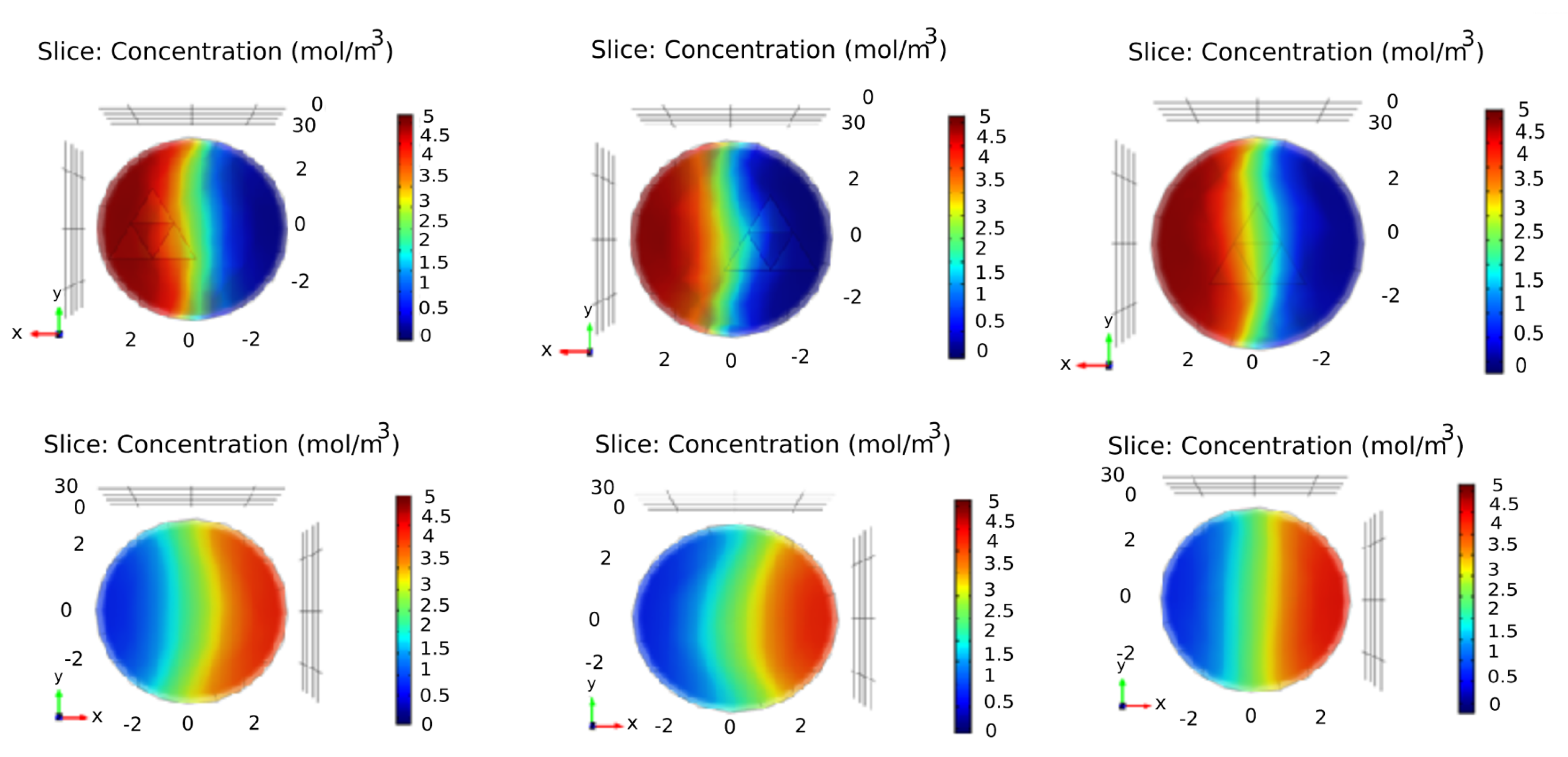
The CoV was used as a parameter to determine the quality of the two-fluid mixture and is a number between zero (best case) and one (worst case) (as we put in Table 1). In row 1, the water fluid table with a concentration of 0 is mixed with a liquid concentration of 5 mol/m 3 by passing through the cube shown in Figure 9. The CoV 0.004 indicates that the two fluids are well mixed. Comparison of rows 2 and 3 shows that if instead of two obstacles in two different halves, three obstacles are placed, and the fluid passes through their sides, we will achieve better quality in mixing the two liquids. (0.28 for three barriers and 0.37 for two barriers) If we compare the cases of 4, 5, 6, it is clear that the passage of fluid through the fractal Sierpinski carpet (first iteration) achieves better results than the passage of fluid through its sides. By comparing three cases 7, 8, 9, it is clear that the combination of square barrier and Sierpinski carpet was used in the patterns. The CoV was 0.44, 0.37, and 0.36. The passage of fluid from the sides of a large Sierpinski triangle (case 10) in the first iteration resulted in the CoV 0.60, which is not a good result. However, when a small Sierpinski triangle was placed in an area with a maximum concentration of 5 mol/m 3 (case 11), it resulted in CoV 0.45. In the case of 12, 13, 14, the Sierpinski carpet with dimensions placed on the right, on the left, and middle halves, but we found that in the third iteration of the Sierpinski carpet, it is impossible to obtain better results than the first iteration.
Table 2 shows the effect of the circular pattern (zero iteration) (case 1) and circular fractals (first iteration) on the two-fluid mixture’s quality. Using one of them led to CoV 0.40, while using two same patterns led to CoV 0.30 and 0.33. Comparing them showed that when the distance between two circular patterns is less, it leads to a smaller CoV. In cases 5 and 6, which were used as circular fractal pattern (second iteration), we found larger CoV.
In cases 1 to 4 of Table 3, triangular patterns were used. The results showed that if we place a triangular barrier in a pipe with a triangular cross-sectional area, it will lead to a smaller CoV 0.22, the triangular barrier in the cylindrical tube 0.44, 0.52, 0.59, which was not satisfactory. For cases where the Sierpinski triangle is in the first, second, and third iterations, the results show that if the fluid passes through these patterns, it will cause a smaller CoV if it passes through the sides of these patterns. Using two or three of the same fractal patterns (in the first iteration) leads to better results than using only one pattern in the second or third iteration.

5. Conclusions

This project’s results included some analytical results and some results from simulation problem-solving in COMSOL Multi-physics software. The fundamental equations governing fluid motion are the Navier–Stokes equations and continuity equations solved by different initial and boundary conditions. We have solved fractal form of Navier–Stokes equations by using F α -calculus. In the analytical part, we could only solve the problem in two-dimensional and single-phase mode. We can implement the fractal equations and analytical results in the physics builder mode inside COMSOL software in future work. It will then enable us to compare the analytical results of the problem solving with the results of numerical simulations. Next, in the main part of the paper, we desire the fractal mixing of two fluids with a ratio of 1:1. The two liquids are mixed by passing through the inside or outside of the fractal patterns. We were dealing with the original body in constructing fractal shapes. The motion of the fluid through inside or outside of the fractal objects was studied. The cross-sectional area was the circle, triangle, and square. Fractal geometric shapes include triangular fractals (Sierpinski triangles), square fractals (Sierpinski carpets), and circular fractal patterns. The simulations show that mixing the two fluids by passing through the fractal pattern is better than passing from the outsides. A parameter called the C o V change coefficient can indicate the quality of mixing the two fluids. We calculated C o V values for several configurations, and the results showed that different C o V values were obtained. Smaller amounts of the CoV make them suitable candidates for usage. The results were as follows:
  • The fractal mixing simulation showed that if the fluid passes through the fractal pattern, it leads to a smaller CoV than it passes through its sides.
  • Using the second and third iterations instead of the first iteration of a fractal pattern does not necessarily lead to better quality in mixing of the two fluids.
  • Using more than one fractal pattern in the path can decrease CoV to a smaller value. Of course, the shorter distance between the two fractal patterns, the better efficiency will be.
  • Simulation results in mixing two fluids by Sierpinski carpet patterns and the square barrier showed somewhat smaller CoV than the patterns of the Sierpinski triangle and the circular fractal patterns.
  • We can continue the studies by studying the gas–liquid fluids phase and gas–gas fluids phase, while the study area will be extended from laminar flow to turbulent flow.

Author Contributions

Conceptualization, A.P.; funding acquisition, M.D.; investigation, M.D.; methodology, A.P.; software, A.P.; writing—original draft, A.P.; writing—review and editing, A.P. and M.D. All authors have read and agreed to the published version of the manuscript.

Funding

This work was supported by the National University of Malaysia (UKM), grant No: GUP-2019-032.

Data Availability Statement

Not applicable.

Acknowledgments

The authors are sincerely grateful to the editors and anonymous referees for careful reading of the original manuscript and useful comments.

Conflicts of Interest

The authors declare no conflict of interest.

Abbreviations

CoVCoefficient of Variation
FEMFinite Element Method

References

  1. Falconer, K. Fractal Geometry: Mathematical Foundations and Applications, 2nd ed.; Wiley: New York, NY, USA, 2007. [Google Scholar]
  2. Mandelbrot, B.B. The Fractal Geometry of Nature; W. H. Freeman and Company: New York, NY, USA, 1977. [Google Scholar]
  3. Lazopoulos, K.A.; Lazopoulos, A.K. On fractional bending of beams. Arch. Appl. Mech. 2016, 86, 1133–1145. [Google Scholar] [CrossRef]
  4. Sumelka, W. On fractional non-local bodies with variable length scale. Mech. Res. Commun. 2017, 86, 5–10. [Google Scholar] [CrossRef]
  5. Drapaca, C.S.; Sivaloganathan, S. A fractional model of continuum mechanics. J. Elast. 2012, 107, 105–123. [Google Scholar] [CrossRef]
  6. Zingales, M.; Failla, G. The finite element method for fractional non-local thermal energy transfer in non-homogeneous rigid conductors. Commun. Nonlinear Sci. Numer. Simul. 2015, 29, 116–127. [Google Scholar] [CrossRef] [Green Version]
  7. Parvate, A.; Gangal, A.D. Calculus on fractal subsets of real-line I: Formulation. Fractals 2009, 17, 53–148. [Google Scholar] [CrossRef]
  8. Parvate, A.; Gangal, A.D. Calculus on fractal subsets of real line II: Conjugacy with ordinary calculus. Fractals 2011, 19, 271–290. [Google Scholar] [CrossRef]
  9. Gangal, A.D.; Parvate, A.; Satin, S. Caclulus on fractal curves in rn. Fractals 2011, 19, 15–27. [Google Scholar]
  10. Gangal, A.D.; Satin, S. Langevin equation on fractal curves. Fractals 2016, 24, 1650028. [Google Scholar]
  11. Gangal, A.D.; Satin, S.; Parvate, A. Fokker-planck equation on fractal curves. Chaos Solitons Fractals 2013, 5, 30–35. [Google Scholar]
  12. Golmankhaneh, A.K.; Fernandez, A. Fractal Calculus of Functions on Cantor Tartan Spaces. Fractal Fract. 2018, 2, 30. [Google Scholar] [CrossRef] [Green Version]
  13. Balankin, A.S.; Golmankhaneh, A.K. Sub- and super-diffusion on cantor sets: Beyond the paradox. Phys. Lett. A 2018, 382, 960–967. [Google Scholar]
  14. Golmankhaneh, A.K.; Baleanu, D. Non-local Integrals and Derivatives on Fractal Sets with Applications. Open Phys. 2016, 14, 542–548. [Google Scholar] [CrossRef]
  15. Golmankhaneh, A.K.; Baleanu, D. Calculus on Fractals. In Fractional Dynamics; De Gruyter Open: Basel, Switzerland, 2015; pp. 307–332. [Google Scholar]
  16. Jafari, F.K.; Asgari, M.S.; Pishkoo, A. Fractal calculus for fractal materials. Fractal Fract. 2019, 3, 8. [Google Scholar] [CrossRef] [Green Version]
  17. Delfan, N.; Pishkoo, A.; Azhini, M.; Darus, M. Using fractal calculus to express electric potential and electric field in terms of staircase and characteristic functions. Eur. J. Pure Appl. Math. 2020, 13, 19–32. [Google Scholar] [CrossRef] [Green Version]
  18. Golmankhaneh, A.K.; Golmankhaneh, A.K.; Baleanu, D. About Maxwell’s equations on fractal subsets of R3. Open Phys. 2013, 11, 863–867. [Google Scholar] [CrossRef] [Green Version]
  19. Golmankhaneh, A.K.; Golmankhaneh, A.K.; Baleanu, D. About Schrödinger Equation on Fractals Curves Imbedding in R3. Int. J. Theor. Phys. 2015, 54, 1275–1282. [Google Scholar] [CrossRef]
  20. Golmankhaneh, A.K. On the Fractal Langevin Equation. Fractal Fract. 2019, 3, 11. [Google Scholar] [CrossRef] [Green Version]
  21. Fernandez, A.; Golmankhaneh, A.K. Random variables and stable distributions on fractal cantor sets. Fractal Fract. 2019, 3, 31. [Google Scholar]
  22. Cattani, C.; Golmankhaneh, A.K. Fractal logistic equation. Fractal Fract. 2019, 3, 41. [Google Scholar]
  23. Fractal-Mixing. Available online: http://www.arifractal.com/technologies-applications/fractal-mixing (accessed on 5 February 2021).
  24. Baldyga, J.; Bourne, J.R.; Dubuis, B.; Etchells, A.W.; Gholap, R.V.; Zimmermann, B. Jet reactor scale-up for mixing controlled reactions. Chem. Eng. Res. Des. 1995, 73, 497. [Google Scholar]
  25. Fournier, M.C.; Falk, L.; Villermaux, J. A new parallel competing reaction system for assessing micro-mixing efficiency—Experimental approach. Chem. Eng. Sci. 1996, 51, 5053–5064. [Google Scholar] [CrossRef]
  26. Sutherland, W.S. Improvement in Apparatus for Preparing Gaseous Fuel. UK Patent 1784, 1874. [Google Scholar]
  27. Les Consommateurs de Petrole. Dispositif pour le mélangede deux ou plusieurs fluides. French Patent 735,033, 1931.
  28. Bakker, M.J. Dispositif pour préparer du béton ou unematière analogue. French Patent 959,155, 1949. [Google Scholar]
  29. Lynn, R.S. Turbulator. U.S. Patent 2,852,042, 1958. [Google Scholar]
  30. Stearns, R.F. Method and Apparatus for Continuous Flow Mixing. U.S. Patent 2,645,463, 1953. [Google Scholar]
  31. Tollar, J.E. Interfacial Surface Generator. U.S. Patent 3,239,197, 1966. [Google Scholar]
  32. Static Mixing: Advanced Mixing Technology. Available online: https://www.fluitec.ch/download.php?f=3fe420f8be822be48f8d6fe85fdfb79f (accessed on 5 February 2021).
  33. Veasey, T.M. Plate Type Fluid Mixer. U.S. Patent 3,382,534, 1968. [Google Scholar]
  34. Thakur, R.K.; Vial, C.; Nigam, K.D.P.; Nauman, E.B.; Djelveh, G. Static mixers in the process industries—A review. Trans. IChemE 2003, 81, 787–826. [Google Scholar] [CrossRef]
  35. Baker, J.R. Motionless mixers stir up new uses. Chem. Eng. Prog. 1991, 87, 32–38. [Google Scholar]
  36. Myers, K.J.; Bakker, A.; Ryan, D. Avoid agitation by selecting static mixers. Chem. Eng. Prog. 1997, 93, 28–38. [Google Scholar]
  37. Yang, X.-J.; Baleanu, D.; Tenreiro Machado, J.A. Systems of Navier–Stokes Equations on Cantor Sets. Math. Probl. Eng. 2013, 2013, 769724. [Google Scholar]
  38. Otarod, S.; Otarod, D. Analytical Solution For Navier–Stokes Equations In Two Dimensions For Laminar Incompressible Flow. arXiv 2006, arXiv:physics/0609186v1. [Google Scholar]
  39. Chapra, S.C.; Canale, R.P. Numerical Methods for Engineers; McGraw-Hill Education: New York, NY, USA, 2015. [Google Scholar]
Figure 1. The u component (Equation (22)) is the fluid velocity in the fractal space for the function f = β S F α ( x ) + γ S F α ( y ) for which α = 0.63 , β = 1 , γ = 1 , A = 1 , B = 1 , c = 1 .
Fractalfract 05 00016 g001
Figure 2. The v component (Equation (23)) is the fluid velocity in the fractal space for the function f = β S F α ( x ) + γ S F α ( y ) for which α = 0.63 , β = 1 , γ = 1 , A = 1 , B = 1 , c = 1 .
Fractalfract 05 00016 g002
Figure 3. The u component (Equation (26)) is the fluid velocity in the fractal space for the function f = exp ( β S F α ( x ) + γ S F α ( y ) ) for which α = 0.63 , β = 1 , γ = 1 , A = 1 , B = 1 , c = 1 .
Fractalfract 05 00016 g003
Figure 4. The v component (Equation (27)) is the fluid velocity in the fractal space for the function f = exp ( β S F α ( x ) + γ S F α ( y ) ) for which α = 0.63 , β = 1 , γ = 1 , A = 1 , B = 1 , c = 1 .
Fractalfract 05 00016 g004
Figure 5. Convergence diagram showing the error estimation in the first iteration of Sierpinski carpet.
Fractalfract 05 00016 g005
Figure 6. Fluid velocity magnitude distribution for fractals in the zero, first, and second iterations.
Fractalfract 05 00016 g006
Figure 7. Sierpinski carpet object in high concentration area in the second iteration for input (front up view-right), and for output (rear up view-left), Fractal in low concentration area in the second iteration for input (front down view-right), and for output (rear down view-left).
Fractalfract 05 00016 g007aFractalfract 05 00016 g007b
Figure 8. Fractal cross-section of the first iteration of a circle through which current flows (right), Fractal cross-section of the first iteration of a circle through which current flows twice with zero and 45 degrees (center), Fractal cross-section of the second iteration of a circle through which current flows (left).
Fractalfract 05 00016 g008
Figure 9. Sierpinski triangle object in center area in the first iteration for input (front up view-right), and for output (rear down view-right), Sierpinski triangle in low concentration area in the first iteration for input (front up view-center), and for output (front down view-center), and Sierpinski triangle object in high concentration area in the first iteration for input (front up view-left), and for output (rear down view-left).
Fractalfract 05 00016 g009
Table 1. Values of CoV, which indicates the quality of mixing the two fluids using Sierpinski carpet patterns and obstacles with a square cross-section.
GeometryPosition-Fluid MovesIteration NumberAverage Concentration
c ¯  (mol/m 3 )
Standard Deviation
σ
CoV
σ c ¯
Fractalfract 05 00016 i001center-inside02.37370.01030.004
Fractalfract 05 00016 i002center-inside12.54471.46840.57
Fractalfract 05 00016 i003center-outside12.54231.54680.60
Fractalfract 05 00016 i004left-outside12.79511.26340.45
Fractalfract 05 00016 i005left-right-outside02.58190.97200.37
Fractalfract 05 00016 i0062left-right-outside12.67810.98150.36
Fractalfract 05 00016 i0072left-right-outside02.81650.79360.28
Fractalfract 05 00016 i008center-outside32.44211.59080.65
Fractalfract 05 00016 i009left-outside32.60131.35150.51
Table 2. Values of CoV, which indicates the quality of mixing the two fluids using Sierpinski triangle patterns and obstacles with circular cross-section.
GeometryPosition-Fluid MovesIteration NumberAverage Concentration
c ¯  (mol/m 3 )
Standard Deviation
σ
CoV
σ c ¯
Fractalfract 05 00016 i010right-outside12.46451.40820.57
Fractalfract 05 00016 i011center-outside22.41441.49520.61
Fractalfract 05 00016 i012center-outside22.41991.52250.62
Fractalfract 05 00016 i013center-outside32.45321.49530.55
Fractalfract 05 00016 i014left-outside12.54471.46840.57
Fractalfract 05 00016 i015center-outside12.58021.52400.59
Fractalfract 05 00016 i016right-outside12.58171.42260.55
Fractalfract 05 00016 i017left-outside02.62971.38080.52
Fractalfract 05 00016 i018right-outside02.64971.32420.49
Table 3. Values of CoV, which indicates the quality of mixing the two fluids using the circular fractal patterns and obstacles with triangle cross-section.
GeometryPosition-Fluid MovesIteration NumberAverage Concentration
c ¯  (mol/m 3 )
Standard Deviation
σ
CoV
σ c ¯
Fractalfract 05 00016 i019left-outside02.70111.18280.43
Fractalfract 05 00016 i020center-inside12.89751.21150.41
Fractalfract 05 00016 i021center-inside-rotated 45 22.82081.25380.51
Fractalfract 05 00016 i022center-inside22.65881.54690.58
Fractalfract 05 00016 i023two-center-inside22.85380.94860.33
Fractalfract 05 00016 i024two-center-outside22.45321.49530.55
Publisher’s Note: MDPI stays neutral with regard to jurisdictional claims in published maps and institutional affiliations.