Abstract
In order to solve parameter fluctuations and disturbances, a novel fractional order model reference adaptive speed observer that estimates the rotor position and the angular velocity from the stator currents is proposed for sensorless control of permanent-magnet synchronous motors (PMSM). Firstly, a novel fractional order model reference adaptive controller (FOMRAC) for adaptive identification is designed to achieve fast response and high precise identification of load torque in the full speed range when the motor is running at variable-speed or variable-load. Additionally, an appropriate adjustable matrix P is chosen to make the convergence of the adaptive law meet the requirements. Next, an improved model reference adaptive observer (MRAO) is proposed to suppress the serious chattering and compensate rotor position error, which can stabilize the system. The validity of the proposed fractional order model reference adaptive sensorless control strategy for PMSM is demonstrated with simulations.
1. Introduction
Permanent-magnet synchronous motors (PMSMs) have been widely used in many industrial applications due to their advantages of high efficiency, fast response and high power density, and light weight [1,2]. In recent years, many other control approaches have been studied for PMSM servo systems, such as robust control [3], sliding mode control [4], adaptive control [5,6], internal model control, and [7] so on. These approaches improve the performance of PMSM control from different aspects.
As a generalization of integer calculus, fractional calculus can describe the actual physical objects more accurately. Fractional calculus has attracted more and more attention in engineering and physics, such as physical modeling, controller design, chaotic systems, and so on. For a long time, it was considered as a purely theoretical subject with nearly no applications. However, in recent decades the application of fractional controller has attracted increasing attention due to the greater degree of freedom that it provides [8].
Fractional operators can be found in many fields; fractional controllers have two more parameters compared with integer-order controllers as well as fractional orders of integral and differential parts. They provide more flexibility to achieve better robustness and tracking performance for control systems [9].
Many articles are devoted to changing the integer order controller to the fractional order controller to obtain a more flexible and smooth control characteristic that leads to better system performance compared with ordinary controllers using integer operators. In [10], fractional order PI and PID control methods focus on the parameter turning, while the sliding mode controller in [11] and observer in [12] for PMSM make up for shortfalls of FOPID and show great efficiency in PMSM velocity control, because in [13] the tracking error of drive system converges to zero faster and superior than other controllers under the existence of load disturbance. In [14], a model reference adaptive system (MRAS) was formed using the instantaneous and steady-state reactive powers to estimate the speed, which caused less dependence on parameter estimation.
The kind of adaptive controller varies in accordance with the change in plant parameters, which contains a variety of control methods. Among all of them, model reference adaptive control is one of the most important approaches. MRAC (model reference adaptive controller) is simple and requires less computation due to it forcing the controlled system to be in a desired state using two different models. However, the simple structure follows with much dependence on the accuracy of the model. Ref. [15] points out that the MRAS flux observer’s sensitivity to the rotor resistance variation is much lower than that of the conventional flux estimator, especially for low speeds of the induction motor. Plenty of works have been performed to reduce the dependency of model accuracy in MRAS, such as weakening the influence of parameters and stator resistance on PMSM by using reactive power to estimate the speed, or adding more degree-of-freedom estimators [16]. That being said, it is useful to improve the performance of MRAC by increasing the precision of the PMSM model or using a new controller with more accuracy [17]. Very few studies in the previous research have combined a fractional order model with MRAO due to the difficulty of demonstrating uniform stability in the sense of Lyapunov for fractional order systems.
Many mathematicians have been attracted to estimating FOS (fractional order state) with adaptive control and show great performance in error tracking and parameter adjustment, especially in fractional order model reference adaptive control (FOMRAC) in [18,19]. In [20], the fractional order reference model in MRAC is employed and a novel rule to demonstrate the stability of MRAS is given, but this rule has some limitations on stability analysis in the frequency domain. Ref. [21] proposes two novel lemmas related to the Caputo fractional derivatives that make up for the lack of fractional order extension of the Lyapunov direct method. Additionally, this paper presents a stability analysis of FOS by using the Lyapunov direct method. To estimate the exact initial states of FOS and deal with the initial condition problem, [22] proposes a fixed-pole approximation method; [23] gives a solution to estimate uncertain FOS adaptive control in SISO(Simple Input Simple Output) and MIMO systems via the continuous frequency disturbance model and indirect Lyapunov method, making it possible for fractional order mechanism to incorporate the new adaptive control; In [24], the optimal control problem limited by the constraint that the resulting controller be strictly positive real is studied; and the MRAS controller and observer parameters are turned using the strictly positive real matrices theory in [25].
Most of the previous MRAC methods employed for PMSM control utilize integer derivatives in their controller and adaptation mechanism. In this paper, a fractional-order adaptive law verified strictly using the Lyapunov direct method is incorporated into conventional MRAC to reduce the tracking error of the observer and the influence of load disturbance. Moreover, the new fractional order adaptive law employed for fractional derivatives of PMSM signals (such as speed error, reference speed) is compared with ordinary MRAS to verify the closed-loop system robust stability under mechanical parameter variations.
Reference [26] uses model reference adaptive control, but the accuracy of this method depends on the accuracy of the motor parameters. Reference [27] adds sliding mode link to the speed ring to improve the robustness of the system. In reference [28], the complex domain is used to define the motor stator current for the adaptation mechanism of the adaptive algorithm, and the adaptive algorithm under complex values is written for the PI gain controller and the rotation speed is estimated, but it is only applied to the induction motor. Regarding the comparison of different speed observers for the vector control PMSM drive, the sliding mode observer (SMO) and the model reference adaptive system (MRAS), a comprehensive analysis of SMO and MRAS considering dynamic, steady-state performance and robustness as well as affectability, stability, and computational complexity was conducted in [29]. Besides, this study optimized the traditional MRAS and sensorless control theory, but only added a partial active anti-disturbance control, with poor robustness and optimization degree improvement. A novel fractional order adaptive sliding mode controller (FOASMC) was designed to realize the speed control of a permanent-magnet synchronous motor (PMSM) with matched model uncertainties and load disturbances in [30], but its algorithm is only applicable to the variable flux motor with combined magnetic poles. Therefore, the fractional order model reference adaptive controller is rarely applied in the field of motor control, which is not only related to its own limitations, but also related to people’s lack of understanding of fractional order motors.
The three-phase permanent-magnet synchronous motor is a multivariable system, and there is a nonlinear coupling relationship between the parameters. It is a challenging task to achieve high performance control of a three-phase permanent-magnet synchronous motor. It is impossible to control the permanent-magnet synchronous motor with only a simple control system. An excellent control strategy can not only make up for the lack of hardware design, but also further improve the performance of the system. The control strategy plays a vital role in AC servos. The requirements of a high-performance AC (Alternation Current) servo system for control strategies can be summarized as follows: not only should the system have fast dynamic response and high dynamic and static accuracy, but the system should also be insensitive to parameter changes and disturbances.
In this paper, a comprehensive algorithm model based on the modal reference adaptive control strategy is proposed. The research focus is the application of a fractional order model reference adaptive controller to the closed-loop control of a permanent-magnet synchronous motor. The important problem to be solved is to demonstrate the stability of the closed-loop system and the design of an appropriate adaptive control rate. A stator current observer based on the model reference adaptive method is proposed to estimate rotor position and velocity. The state unknown motor in operation is taken as the reference model, and the adaptive rate is designed to make the adjustable motor model approximate the reference model. In order to ensure the effectiveness of the adaptive rate and the stability of the designed observer, the results are analyzed by using the strict positive real theorem. The fractional permanent-magnet synchronous motor and the model reference adaptive observer were built on the Simulink platform to ensure that the adaptive rate satisfies Popov’s superstability theorem. A fractional order controller based on the model reference adaptive is proposed. An expected state is designed as the reference model of the motor, and the running motor is taken as the adjustable model. Under this condition, the designed control can effectively cooperate with the model reference adaptive observer and increase the tracking accuracy of the observer. The adaptive rate was designed via the Lyapunov direct method and the stability of the controller was evidenced using a series of fractional order theorems.
The paper is organized as follows: Section 2 describes the mathematical model of FOPMSM under the Caputo fractional derivative and some lemmas about the fractional order extension of the Lyapunov direct method. Rotational speed estimation based on the model reference adaptation observer (MRAO) is introduced in Section 3. A speed estimation scheme of FOMRAC based on MRAO is introduced in Section 4. Simulation results given in Section 5 demonstrate the efficiency of the proposed method. Conclusions including a discussion on future perspectives are given in Section 6.
2. Fractional-Order Calculus Fundamentals
2.1. Mathematical Model of FOPMSM
Assuming that the surface-mounted PMSM has symmetrical structure and symmetrical three-phase current, the PMSM operating environment is stable, and the iron losses, eddy-current losses and saturation effect are ignored, we can then ignore the impact on coil resistance. The d-q axis voltage equations can be expressed as follows:
The mechanical motion equation of PMSM is written as follows:
where represent the stator voltages and stator currents under the d-q axis; represents the stator resistance; represent the d and q-axis stator inductances; represents the rotor angular velocity; represents the permanent magnet flux linkage; represents the moment of inertia; represents the electromagnetic torque; represents the viscous friction coefficient; and represents the load torque.
The variation of the inductances is slower than the current fluctuation, so the model can be rewritten in a linear and time-invariant plant to employ the model reference adaptive controller, given by:
To describe the fractional-order system model in detail, we introduce the Caputo definition in [26]. Compared with the Riemann–Liouville (RL) definition, the Caputo definition contains the initial condition of x(t) in α > 0 derivative and the behavior of ordinary RL and RLC circuits in the fractional order is 0 < α < 1 [2]. The equivalent circuits of PMSM can be considered as RL circuits, so the Caputo definition is widely used in engineering applications.
Definition 1.
(Caputo fractional derivative [26]) The Caputo fractional derivative of order α∈+ on the half axis + is defined as follow:
with .
Therefore, the mathematical model of fractional-order PMSM can be written as:
Considering physical significance, the fractional order in the d-axis should be equal to the q-axis, because they are the components of the same current in the d–q coordinate system.
2.2. Miscellaneous Concepts
Lemma 1.
(Ref. [27]) Let x(t)∈+ be a differentiable vector. Then, for any time instant
Theorem 1.
(Fractional order extension of Lyapunov direct method [5]). Let x = 0 be an equilibrium point of the non-autonomous fractional order system. Let us assume that there exists a Lyapunov function V(x(t),t) and class-K functionssatisfying:
where α∈ [0,1]; therefore, the origin of the system is asymptotically stable.
Lemma 2
(Ref. [20]) Let be a vector of differentiable functions. Then, for any time instant , the following relationship holds:
where is a constant, square, symmetric and positive definite matrix.
Lemma 3
([Ref. 20]) Let be a time-varying differentiable matrix. Then, for any time instant , the following relationship holds:
Theorem 2.
where u is the input vector, x is the output vector of the feedback block, and is a finite positive constant.
(Popov’s hyperstability criterion [11]) The class of feedback system is said to be asymptotically stable if the following two conditions hold:
- (1)
- Feed-forward gain of the system must be real-positive. In other words, the transfer function of the feed-forward linear time invariant block must be strictly positive real.
- (2)
- The error should converge asymptotically, i.e., the nonlinear time varying block satisfies Popov’s integral inequality:
Lemma 4.
(Strictly positive real (SPR) [29]) As for , given δ > 0, a matrix A such that |sI−A| has only zeros in the open left half plane, a real vector b such that (A,b) is completely controllable, a real vector D, a scalar ψ, and an arbitrary real symmetric positive definite matrix L (), then a real vector q and real matrix satisfying:
exist if and only if δ is sufficiently small and .
3. Speed-Estimation-Based MRAO
3.1. Design of the MRAO
The block diagram of the speed-estimation-based MRAO is shown in Figure 1. This method contains two different models (i.e., the reference model and the adjustable model). The error between the two models is used to estimate unknown parameters. There are two kinds of observer based on the input signal of two models: one is the current observer and the other is the flux observer. Each of these observers’ adjustable models relies on the unknown parameters of PMSM (in this paper the unknown parameter is estimative rotor velocity (). Contrary to the adjustable model, the reference model should be independent of the speed. The output of the adaptation mechanism is the estimated quantity, which is used for the tuning in the adjustable model and also for feedback. The stability of such a closed loop estimator is achieved through Popov’s hyperstability criterion [11]. The method is simple and requires less computation.
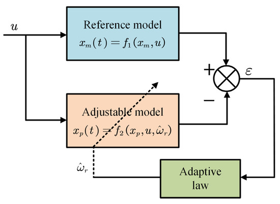
Figure 1.
Block diagram of the speed-estimation-based MRAO.
In spite of the model of PMSM we used being fractional-order, the current signal collected from SVPWM (Space Vector Pulse Width Modulation) is definitely not fractional-order. Because these outputs from the reference model are normal d-q axis currents and the aim of the adjustable model is to make its output follow the reference model outputs, the adaptive law of the current observer can employ an integer-order mechanism.
3.2. Adaptation Mechanism
Several steps were sorted out from the previous research about designing the adaptation mechanism, and one of the most important steps is to formulate the equivalent model.
Step-1: Formulation of the equivalent model
The error between two models can be written as:
Therefore, the can be expressed by .
where is the estimation of ,, is the output of the feedback nonlinear tine varying block without having any external signal () in Figure 2 and ,.
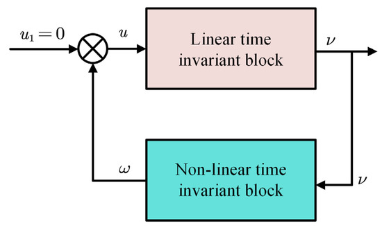
Figure 2.
Block diagram of nonlinear time varying feedback system.
According to the general structure of the adaptation law, the can be expressed in the form of:
The structure of the adaptation mechanism is able to satisfy Popov’s hyperstability criterion. Therefore, we employ for the output of the linear block and D(s) is the linear compensator of the non-linear time variance block in Figure 3.
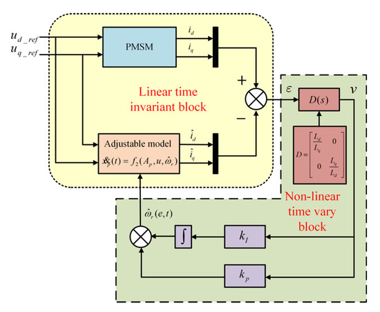
Figure 3.
Structure of the estimator-based MRAO.
Step-2: Select the linear compensator
The selection of the linear compensator is related to the feed-forward gain of the system and should follow Theorem 2 (1). According to Lemma 4, the transfer function matrix is strictly positively real (SPR) only if the transfer function satisfies:
where M is an arbitrary real symmetric positive definite matrix, and we assume that is an unknown real symmetric matrix, which can be written as , in which to simplify the equation, we make .
From the expressions of (14) we can obtain
where |M| > 0 has to be satisfied, and refers to inequality (17):
A series of solutions can be settled from (17). Two solutions are given:
where the feed-forward gain of the system can be strictly positive real in these conditions.
Step-3: The solutions of and
The feedback block satisfies Popov’s integer inequality, which is expressed in (10)
Substituting (18) and (14) in (10), the inequality can be written as:
The above inequality can be split into two inequalities, which are described by (21) and (22):
Assuming that:
Then (20) can be expressed by:
Taking derivation in both sides of the second equation in (22), then substituting the first equation for kf(t):
Let ; we can easily obtain the speed estimator:
Therefore, a simple PI controller in the adaptation mechanism is sufficient to satisfy Popov’s integral inequality. However, to fulfill the other criteria of feed-forward path gain being real and positive, the suitable linear compensator D(s) has to be selected, because it also has influence on the stability of the system in Figure 3.
4. Design of the FOMRAC
4.1. Convergence Analysis
The current observer relies on the accuracy of PMSM model heavily and the error of the observer could be magnified by the variation of parameters because the reference model of the observer is the PMSM itself. To overcome this problem, multiple researches have been performed [9,11,12,13,30]. Almost every article concentrates on the restructuring of the observer to reduce the tracking error, and few of the researches pay attention to the accuracy of the motor. The development of fractional calculus gives us new enlightenment on MRAC. We designed a new MRAC to introduce the fractional order model.
The adjustable model of the controller is the PMSM itself, and we assume that it can be described by the fractional order model, which is:
The above formula can be simplified as:
Then the reference model is
where and r(t) is the uniformly bounded and piecewise–continuous reference input. To control the FOPMSM, the outputs of adjustable model have to keep pace with the reference model gradually, which means:
Therefore, the control input u(t) should be designed as:
in which and are a consisting matrix of adjustable parameters. The parameters in are unknown, therefore we further assume that a constant matrix θ exists and is the estimation of θ. So θ can be expressed as:
Defining the parameter estimation error , and the current control error , the fractional differential equation describing the evolution of the error can be expressed as:
The aim now is to design an adaptive law for adjusting error in such a way that all the signals in the adaptive scheme remain bounded and let the control error approach zero. Here is the adaptive law proposed using the Lyapunov direct method:
4.2. Controller Stabilization
In this section, a fractional order based on the Lyapunov direct method adaptation law is proposed to assure closed-loop system stability in FOPMSM.
Considering the adaptive control law as:
The Lyapunov function candidate should be written as:
where P is a real symmetric positive definite matrix, which is the same as the D matrix in Section 3, and it can be easily confirmed that this Lyapunov function candidate is positive definite.
Involving fractional order calculus in Equation (34), the expression of this Lyapunov function is:
According to Lemma 1,2 and 3, the (14) can be changed by inequality (36)
Substituting (32) and adaptive law (33) in (36), we can obtain:
Then the equality can be divided in two parts, which can be described as:
where M is an arbitrary real symmetric positive definite matrix, so the first part of the fractional order derivative of the Lyapunov function is negative semidefinite, and the next aim is to prove that the second part of the equality is zero or less than zero.
Combining the adaptive law (33) with (37), the rest of the Lyapunov function can be written as
Now using the property for the trace: If , then
So the fractional derivative with respect to time of the Lyapunov function can be expressed as:
which is negative semidefinite. Combining (40) with (34), we use Theorem 1 to prove that the Lyapunov function is asymptotically stable.
This controller exerts reference d-q axis voltages on the FOPMSM. The error of two models tends to zero when the adjustable parameters in the controller are suitable. Moreover, the controller only can be employed when the fractional order α∈ [0,1].
Finally, the detailed block diagram of the proposed MRAC for FOPMSM is shown in Figure 4.
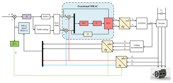
Figure 4.
Control schematic of permanent-magnet synchronous motor based on FOMRAC and MRAO.
5. Simulation
In this section, the performances of the MRAO combined with and without the controller are presented. To facilitate the analysis, the two methods are applied on the condition that FOPMSM’s fractional derivative of order α = 1 is equal to the ordinary derivative. Additionally, a comparison of the performance of the proposed FOMRAC on PMSM and FOPMSM are given with the MRAO to demonstrate the stability of the control method. PMSM parameters used in the simulation work are shown in Table 1.

Table 1.
PMSM parameters.
The analysis was performed by using three states of reference speed, including dynamic state, steady state and low-speed operation. More details are given in Table 2 about the state of reference speed varying with time. The carrier frequency of PWM is set at 10kHz.
Table 2.
Reference speed.
The PID current controllers (without FOMRAC) of the d-q axis are composed using these parameters:
kP = 0.6, kI = 10, kD = 0
The parameters of the speed observer are:
kP = 0.8, kI = 180
switch sample period = 0.000,000,1 s.
5.1. Control Analysis in Order α = 1
5.1.1. Dynamic Performance
For the design of dynamic characteristics, the dynamic process in Table 1 is used: First, the reference speed increases from 0 to 1500 rpm within 0~0.3 s without load torque; after maintaining stable operation for 0.4 s, the motor reverses, the motor speed runs from 1500 rpm to −1500 rpm within 0.7–1.3 s, and the motor finally maintains steady operation within 0.2 s. For the dynamic process, numerical simulation was carried out under the condition that the PMSM has a new controller and no new controller for the model reference adaptive observer. Figure 5a shows the running speed curve of the PMSM with PID and MRAO. Figure 5b is the speed curve of the PMSM when MRAO and FOMRAC are simultaneously connected. As can be seen from the figure, when the FOMRAC is not added, the observer will have a serious jitter phenomenon when the motor is running at high speed, and its error margin is about 25 rpm. However, after FOMRAC is added, the observer can also maintain a stable state when the motor is running at high speed, and the error fluctuation is reduced to 5 rpm. Moreover, at the point where the motor is switched from positive rotation to reverse rotation, the MRAO has a serious jitter phenomenon, which means that the motor cannot be observed when the speed is 0, but after the addition of FOMRAC, the motor can maintain stability at the point above 0 speed. The curves of the PMSM speed under the two conditions are as follows:
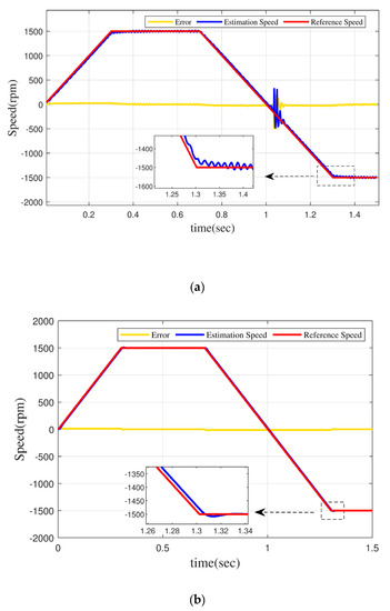
Figure 5.
(a) Normal PID control+MRAO, (b) FOMRAC+MRAP.
Figure 6 shows the angle error of the motor with PID or with FOMRAO under dynamic characteristics. It can be seen that without a new model reference adaptive controller, the rotor position error margin of the motor is relatively high when it runs under dynamic characteristics, reaching 0.4 rad. The rotor position error is only 0.09 rad after adding the MRAO.
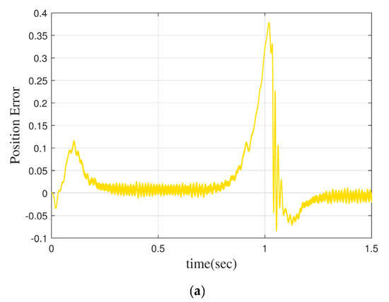
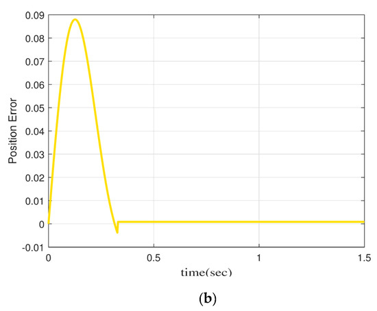
Figure 6.
(a) Normal PID control+MRAO, (b) FOMRAC+MRAO.
5.1.2. Steady-State Performance
In order to study the influence of a controller on the permanent-magnet synchronous motor under the steady-state operation condition, 1 N·m and −1 N·m load torque were added during the stable operation of the motor (maintained at 1500 rpm within 0.5 s), and the objects of numerical simulation experiments were all permanent-magnet synchronous motors based on the MRAO.
Figure 7a,b shows the steady-state speed curve of the PMSM only under the condition of PID and MRAO. It can be seen that after adding 1 N·m load torque, the speed fluctuation range is more than 100 rpm, and the speed stays at 1500 rpm after 0.6 s. However, after the load torque of −1N·m is added, the speed fluctuation still exceeds 100 rpm, and it cannot maintain stable operation under the action of −1 N·m torque.
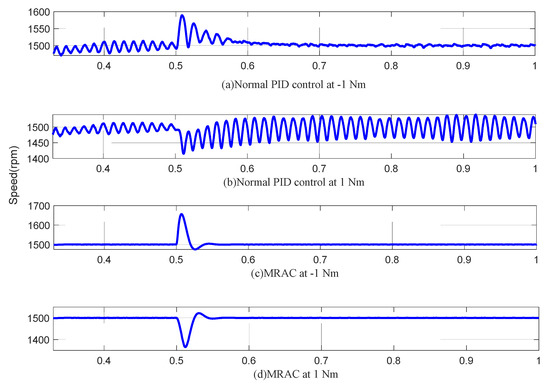
Figure 7.
(a) Normal PID control at −1 N·m; (b) normal PID control at 1 N·m; (c) FOMRAC at −1 N·m; (d) FOMRAC at 1 N·m.
Figure 7c,d shows the speed curve of a permanent-magnet synchronous motor in steady state operation under the condition of FOMRAC and MRAO. It can be seen that after adding 1N·m load torque, the speed fluctuates more than 150 rpm, but recovers to 1500 rpm within 0.03 s. The torque action process of −1 N·m load is similar to that of 1 N·m, both of which can recover to a stable operating state in a short time.
Therefore, the steady-state numerical simulation evidences that the model reference adaptive observer can obtain better steady-state performance of a permanent-magnet synchronous motor under the condition of a model reference adaptive controller.
5.1.3. Low-Speed Performance
In order to explore the influence of the controller on the permanent-magnet synchronous motor at low speed, the permanent-magnet synchronous motor was set to run at a speed of 100 rpm within 0.5 s.
Figure 8a shows the low-speed operation of PMSM based on a model reference adaptive observer with PID. Figure 8b shows the operation of the permanent-magnet synchronous motor with the FOMRAC. It can be seen from the error curve that without the controller, the speed observation error reaches 3 rpm. The observation error of PMSM with the model reference adaptive controller is only 0.6 rpm. Additionally, the time to reach the low-speed steady-state operation is different. The controller-less permanent-magnet synchronous motor uses 0.12 s. The permanent-magnet synchronous motor with controller only uses 0.05 s.
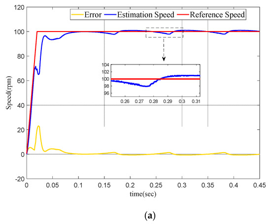
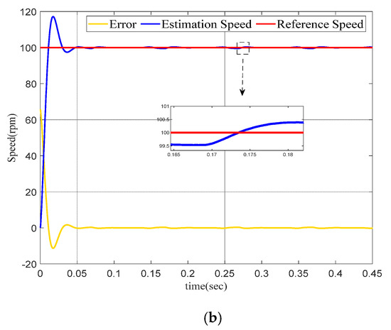
Figure 8.
(a) Normal PID control+MRAO, (b) FOMRAC+MRAO.
5.2. Control Analysis in Fractional Order
In this section, numerical simulation is used to verify the observability of the model and the effectiveness of FOMRAC. Firstly, a fractional order motor model is carried out to obtain the fractional order motor numerical simulation model without a controller. Then, a controller is applied to the fractional order motor simulation model to obtain the fractional order motor numerical simulation with a fractional order controller. Finally, the two are compared to verify the effectiveness of the fractional order controller.
In order to achieve the above purpose, the following simulation experiment is designed: the permanent-magnet synchronous motor speed is increased from 0 to 1500 rpm within 0~0.3 s, the high-speed operation is maintained at 0.7 s, and the load torque of −1 N·m is added during the high-speed operation (0.5 s).
In order to enhance the comparability with or without a fractional order controller, eight kinds of fractional-order motors are introduced in the simulation experiment, which are 0.92, 0.93, 0.95, and 0.97 order permanent-magnet synchronous motors without a controller and 0.7, 0.8, 0.9, and 0.95 order permanent-magnet synchronous motors with a new controller. All permanent-magnet synchronous motors run under the condition of a model reference adaptive observer. The speed curves of fractional PMSM with different orders are shown in Figure 9.
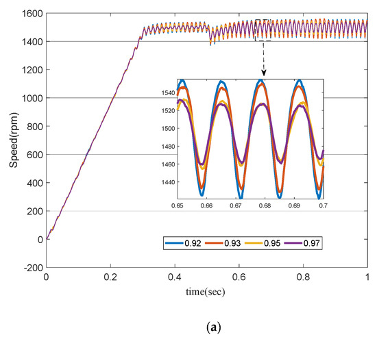
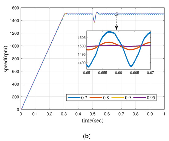
Figure 9.
(a) Normal PID control+MRAO, (b) FOMRAC+MRAO.
Figure 9a shows the dynamic characteristic curve of the permanent-magnet synchronous motor under the condition of using PID and MRAO. As can be seen from the figure, with the continuous decrease in fractional order, the speed of the permanent-magnet synchronous motor becomes more and more unstable at 1500 rpm steady-state operation, the speed fluctuation reaches ±30 rpm at 0.92 order, and the fluctuation amplitude increases to ±50 rpm when the load torque of −1 N·m is added.
Figure 9b shows the dynamic characteristic curve of the permanent-magnet synchronous motor under the condition of FOMRAC and MRAO. Similar to PID and MRAO, the steady-state speed curve also shows fluctuation increase after the order of the fractional permanent-magnet synchronous motor is reduced. However, no matter before or after adding the load torque, the PMSM above the order 0.9 has a small fluctuation range, which is maintained at about ±2 rpm, while the fractional order PMSM below the order 0.9 has a relatively unstable fluctuation, but the maximum speed fluctuation is not more than ±12 rpm.
Numerical simulation evidenced that FOMRAC can make the fractional order dynamic system of a permanent-magnet synchronous motor reach a stable operation state. When the fractional order model has a low order, the fractional order controller is almost the inevitable choice for control; otherwise, it is easy for the motor to enter an unstable operation state.
6. Conclusions
Aiming at the problem that sensorless control of a permanent-magnet synchronous motor cannot be applied in the full speed domain of the PMSM, a novel fractional order model reference adaptive controller for adaptive identification was designed to achieve high precision and high response identification of load torque in the full speed range when the motor is running with variable speed or variable load. The comparison of the proposed fractional order MRAC and normal PID is given under both MRAO based sensorless techniques of PMSM. The proposed method gives good robust performance in actual situations, including the external load torque and uncertainty in fractional order PMSM. Through the comparative analysis, the following conclusions are drawn: the improved MRAO is proposed that can suppress serious chattering and compensate for rotor position error, which can stabilize the system. Fractional-order PMSM is more precise to the actual running state of the motor, and it is more accurate to describe the permanent-magnet synchronous motor with fractional theory. The simulation results show that the FOMRAC can control the fractional PMSM and improve its stability.
Author Contributions
Conceptualization, L.L.; methodology, L.L.; software, H.N.; writing—original draft preparation, H.N.; writing—review and editing, D.J. and S.L.; supervision, L.L., D.J. and S.L.; funding acquisition, H.N. and L.L. All authors have read and agreed to the published version of the manuscript.
Funding
This research was funded by the National Natural Science Foundation of China, grant number 51977173.
Conflicts of Interest
The authors declare no conflict of interest.
References
- Dai, C.; Guo, T.; Yang, J.; Li, S. A disturbance observer-based current-constrained controller for speed regulation of PMSM systems subject to unmatched disturbances. IEEE Trans. Ind. Electron. 2021, 68, 767–775. [Google Scholar] [CrossRef]
- Dong-Woo, S.; Bak, Y.; Lee, K. An improved rotating restart method for a sensorless permanent-magnet synchronous motor drive system using repetitive zero voltage vectors. IEEE Trans. Ind. Electron. 2020, 67, 3496–3504. [Google Scholar]
- Li, L.; Pei, G.; Liu, J.; Du, P.; Pei, L.; Zhong, C. 2-DOF robust h∞ control for permanent-magnet synchronous motor with disturbance observer. IEEE Trans. Power Electron. 2021, 36, 3462–3472. [Google Scholar] [CrossRef]
- Yeam, T.; Lee, D.C. Design of sliding-mode speed controller with active damping control for single-inverter dual-PMSM drive systems. IEEE Trans. Power Electron. 2021, 36, 5794–5801. [Google Scholar] [CrossRef]
- Zhang, X.; Wang, Y.; Wang, C.; Su, C.Y.; Li, Z.; Chen, X. Adaptive estimated inverse output-feedback quantized control for piezoelectric positioning stage. IEEE Trans. Cybern. 2019, 49, 2106–2118. [Google Scholar] [CrossRef] [PubMed]
- El-Sousy, F.F.M.; Amin, M.M.; Aziz, G.A.A.; Al-Durra, A. Adaptive neural-network optimal tracking control for permanent-magnet synchronous motor drive system via adaptive dynamic programming. In Proceedings of the 2020 IEEE Industry Applications Society Annual Meeting, Detroit, MI, USA, 10–16 October 2020; pp. 1–8. [Google Scholar]
- Deng, W.; Xu, J.; Zhao, H.; Song, Y. A novel gate resource allocation method using improved PSO-based QEA. IEEE Trans. Intell. Transp. Syst. 2022, 23, 1737–1745. [Google Scholar] [CrossRef]
- Chen, Y. Impulse Response Invariant Discretization of Frac-Tional Order Integrators/Differentiators, Filter Design and Analysis, MA TLAB Central. Available online: https://www.mathworks.com/matlabcentral/fileexchange/21342-impulse-response-invariant-discretization-of-fractionalorder-integrators-differentiators (accessed on 24 March 2012).
- Luo, Y.; Zhang, T.; Lee, B.; Kang, C.; Chen, Y. Fractional order proportional derivative controller synthesis and implementation for hard-disk-drive servo system. IEEE Trans. Control Syst. Technol. 2014, 22, 281–289. [Google Scholar] [CrossRef]
- Zeng, G.Q.; Chen, J.; Dai, Y.X.; Li, L.M.; Zheng, C.W.; Chen, M.R. Design of fractional order PID controller for automatic regulator voltage system based on multi-objective extremal optimization. Neurocomputing 2015, 160, 173–184. [Google Scholar] [CrossRef]
- Zhang, B.T.; Pi, Y.G.; Luo, Y. Fractional order sliding-mode control based on parameters auto-tuning for velocity control of permanent-magnet synchronous motor. ISA Trans. 2012, 51, 649–656. [Google Scholar] [CrossRef]
- Mujumdar, A.; Tamhane, B.; Kurode, S. Observer-based sliding-mode control for a class of noncommensurate fractional order systems. IEEE/ASME Trans. Mechatr. 2015, 20, 2504–2512. [Google Scholar] [CrossRef]
- Singh, S.; Tiwari, A.N.; Singh, S.N. Performance evaluation of MRAS and SMO based sensorless PMSM drives. World J. Eng. 2020, 17, 347–355. [Google Scholar] [CrossRef]
- Suman, M.; Chandan, C.; Sabyasachi, S. Simulation studies on model reference adaptive controller based speed estimation technique for the vector controlled permanent-magnet synchronous motor drive. Simul. Model. Pract. Theory 2009, 17, 4. [Google Scholar]
- He, Y.; Wang, J.; Wang, Z.; Wang, H.; Wang, Q.; Wei, D.; Zeng, Z. Speed observation for high-speed permanent-magnet synchronous motor with model reference adaptive system. Electr. Drive 2020, 50, 16–22. [Google Scholar]
- Wu, G.; Xiao, X. Speed controller of servo system based on MRAS method. In Proceedings of the IEEE International Conference on Industrial Technology, Churchill, Australia, 10–13 February 2009; pp. 1–5. [Google Scholar]
- Ayten, K.K. Real-Time Speed Control of an Electrically Powered Wheelchair by Using Fractional Order Model Reference Adaptive System Control. Elektron. Ir Elektrotechnika 2018, 24, 24–35. [Google Scholar] [CrossRef]
- Duarte-Mermoud, A.M.; Aguila-Camacho, N. Some Useful Results in Fractional Adaptive Control. In Proceedings of the Sixteenth Yale Workshop on Adaptive and Learning Systems, New Haven, CT, USA, 5–7 June 2013; pp. 51–56. [Google Scholar]
- Vinagre, B.M.; Petrás, I.; Podlubny, I.; Chen, Y. Using fractional order adjustment rules and fractional order reference models in model-reference adaptive control. Nonlinear Dyn. 2002, 29, 269–279. [Google Scholar] [CrossRef]
- Nain, A.; Vats, R.; Kumar, A. Coupled fractional differential equations involving Caputo-Hadamard derivative with nonlocal boundary conditions. Math. Methods Appl. Sci. 2021, 44, 4192–4204. [Google Scholar] [CrossRef]
- Bin, D.; Yiheng, W.; Shu, L.; Yong, W. Estimation of exact initial states of fractional order systems. Nonlinear Dyn. 2016, 86, 2061–2070. [Google Scholar]
- Shi, B.; Yuan, J.; Dong, C. On fractional model reference adaptive control. Sci. World J. 2014, 9. [Google Scholar] [CrossRef]
- Singh, A.; Shukla, A.; Vijayakumar, V.; Udhayakumar, R. Asymptotic stability of fractional order (1, 2] stochastic delay differential equations in Banach spaces. Chaos Solit. Fract. 2021, 150. [Google Scholar] [CrossRef]
- Damaren, C.J. Optimal strictly positive real controllers using direct optimization. J. Frankl. Inst. 2006, 343. [Google Scholar] [CrossRef]
- Larbi, M.; Roufaida, A.; Nawal, A.A.M. Sensorless control of PMSM with fuzzy model reference adaptive system. Int. J. Power Electr. Drive Syst. 2019, 10. [Google Scholar]
- Hu, B.; Kang, L.; Cheng, J.; Linghu, J.; Zhang, Z. Integrated dead-time compensation and elimination approach for model predictive power control with fixed switching frequency. IET Power Electr. 2019, 12, 1220–1228. [Google Scholar] [CrossRef]
- Zerdali, E.; Menguc, E.C. Novel Complex-Valued Stator Current-Based MRAS Estimators With Different Adaptation Mechanisms. IEEE Trans. Inst. Meas. 2019, 68, 3793–3795. [Google Scholar] [CrossRef]
- Sun, X.; Meng, L.; Liu, Y.; Wang, K. Research on PMSM Direct Torque Speed Control System with Speed Sensorless. In Proceedings of the 14th IEEE Conference on Industrial Electronics and Applications ( ICIEA), Xi’an, China, 19–21 June 2019. [Google Scholar]
- Qiao, G.; Mingqiao, W.; Liu, L.; Liu, Y.; Zheng, P.; Sui, Y. Analysis of Magnetic Properties of Al Ni Co and Magnetization State Estimation in Variable-Flux PMSMs. IEEE Trans. Mag. 2019, 55, 1–6. [Google Scholar]
- Yang, Y.; Chen, J.; Chu, Y.; Wang, Y.; Liang, Q. Fractional order adaptive sliding mode controller for permanent-magnet synchronous motor. In Proceedings of the 35th IEE Chinese Control Conference (CCC), Chengdu, China, 27–29 July 2016. [Google Scholar]


Disclaimer/Publisher’s Note: The statements, opinions and data contained in all publications are solely those of the individual author(s) and contributor(s) and not of MDPI and/or the editor(s). MDPI and/or the editor(s) disclaim responsibility for any injury to people or property resulting from any ideas, methods, instructions or products referred to in the content. |
© 2022 by the authors. Licensee MDPI, Basel, Switzerland. This article is an open access article distributed under the terms and conditions of the Creative Commons Attribution (CC BY) license (https://creativecommons.org/licenses/by/4.0/).