Article

Fixed-Time Multi-Switch Combined–Combined Synchronization of Fractional-Order Chaotic Systems with Uncertainties and External Disturbances

School of Mathematics and Statistics, Sichuan University of Science and Engineering, Zigong 643000, China
*
Author to whom correspondence should be addressed.
Fractal Fract. 2023, 7(4), 281; https://doi.org/10.3390/fractalfract7040281
Submission received: 6 February 2023 / Revised: 12 March 2023 / Accepted: 14 March 2023 / Published: 24 March 2023
(This article belongs to the Section Complexity)

Abstract

:
In this paper, the fixed-time multi-switch combination–combination synchronization (FTMSCCS) of fractional-order chaotic systems with uncertainties and external disturbances is studied. The appropriate sliding mode surface and controller are proposed based on a Lyapunov theorem, and fixed-time multi-switching combination–combination synchronizations between four fractional-order chaotic systems are realized. The Lyapunov function is designed to prove the feasibility of the controller theoretically, and the effectiveness and robustness of the synchronization mechanism are further verified by numerical simulations. The advantage of this article is that it extends fixed-time synchronization to multi-switch combination–combination synchronization, enabling synchronization for a limited time, while increasing the complexity of the synchronization mechanism and improving its confidentiality in communication applications.

1. Introduction

In the last few decades, the study of chaotic systems has received increasing attention. Chaos is a complex and fascinating natural phenomenon. It has complex, unpredictable behavior, is dependent on changes in initial conditions and parameters, and it exists in many classical systems, including the Lorenz system [1], Chen system [2], PMSM system [3], etc. Since Pecora and Carroll first considered the problem of chaos synchronization in 1990 [4], the practical application of chaos synchronization in chemical reactions, power transformation, information processing and other fields has attracted more and more attention. Currently, an increasing number of synchronization approaches are studied, for example, drive response synchronization [5], projection synchronization [6], adaptive fuzzy synchronization [7], neural network synchronization [8], feedback synchronization [9], pulse synchronization [10], and sliding mode synchronization [11].
Fractional calculus is the promotion of integer calculus, which has the same long history as integer calculus. However, due to limited computing power in the past, it was not paid attention to until recent decades with the improvement of computing power [12]. Compared with integral calculus, fractional calculus can describe chaotic and nonlinear phenomena more accurately. With the rapid development of chaos theory and application research, researchers have been widely concerned with the synchronization of fractional chaotic systems, and this field has developed rapidly over the last few years. In 2016, Wang et al. studied the synchronization of fractional-order chaotic systems with uncertain parameters [13]. Huang et al. [14] studied synchronization and anti-synchronization in a class of financial systems in 2017. In 2018, Mohammadzadeh proposed the synchronization of a time-delay fractional system [15]. In 2020, Zhang and Wu found synchronization of chaotic systems of different dimensions [16]. Haris et al. designed a new nonlinear feedback controller to realize synchronization of chaotic systems with unknown parameters [17]. In 2021, Ababneh studied synchronization and anti-synchronization between fractional-order chaotic optical systems with unknown parameters by designing an adaptive controller [18]. In 2022, Li et al. proposed a new global Mittag–Leffler synchronization criterion for fractional-order hyperchaotic financial systems by designing appropriate pulse control and state feedback controllers [19]. However, these control methods can only achieve asymptotic synchronization and stability; that is to say, they cannot achieve accurate convergence in a limited time. Moreover, we cannot estimate the convergence time of these control methods in advance. In actual situations, it is extremely important to achieve a stable and synchronous state within a specified time, especially for those applications that require precise convergence and strict settling time limitations. High-precision convergence in finite time can be realized by finite time control, but convergence time is determined by the initial conditions. However, it is difficult to obtain accurate initial condition information in practical applications; because of this, estimating the convergence time is challenging, and finite-time control’s convergence time approaches infinity, as do the initial circumstances. In order to overcome the limitation of initial conditions and obtain better response performance, Polyakov proposed a fixed-time control strategy [20]. The upper bound of stability time in this control strategy is independent of the initial conditions of the system. On the basis of the fixed-time stability theorem, more and more articles have been written about fixed-time synchronization; for example, [21,22] introduced the fixed-time synchronization of fractal-order chaotic systems. In Reference [23], an adaptive control method is added on the basis of sliding mode control to realize the synchronization of second-order chaotic systems. In this paper, fixed-time synchronization of chaotic systems with different dimensions is proposed and extended to network systems [24].
However, the above synchronization is restricted to one drive and one responsive system. In the last several years, some new synchronization schemes have appeared, among which many chaotic systems are concerned, such as combinatorial synchronization [25,26], composite synchronization [27] and dual composite synchronization [28]. In 2008, Ucar et al. proposed a multi-switch synchronization scheme [29]. It is a significant improvement over the current synchronization system. According to this plan, the various states of the driving system and the required states of the response system are synchronized. In 2011, Wang et al. realized the multi-switch synchronization of chaotic systems with unknown parameters [30]. In 2015, Vincent et al. first combined multi-switch synchronization and combined synchronization to achieve multi-switch synchronization between multiple chaotic systems [31]. Zheng et al. realized the synchronization of three different chaotic systems in 2016 by means of nonlinear control [32]. In 2017, Song et al. used Lorenz and Chen chaotic systems to achieve fractal-order multi-switch synchronization [33]. This synchronization method has been generalized to the uncertain fractional-order chaotic system in the literature [34]. In 2019, Zhang et al. realized the multi-switch combination synchronization of spatiotemporal coupled systems using the backstepping method [35]. Reference [36] proposed a new adaptive anti-synchronization control to realize multi-switch anti-synchronization between two driving systems and one system. In 2020, Muhammad et al. realized multi-switch combination synchronization between multiple chaotic systems of different orders [37]. The benefit of this is that it becomes nearly impossible for an intrusive party to ascertain which combinations are likely to be synchronized because the error system grows to such a size. These schemes provide significant resistance and anti-attack capabilities for secure communication. At present, multi-switch combination synchronization has been applied to finite time synchronization [38], but there are no related articles on fixed time. This paper combines fixed-time synchronization with multi-switch synchronization, and realizes multi-switch combination–combination synchronization with fixed time using an appropriate sliding mode surface and controller. In practical application, it is difficult to obtain a definite system; most systems have uncertainty and external interference. Therefore, this paper presents the fixed-time multi-switch combination–combination synchronization (FTMSCCS) of fractional-order chaotic systems with uncertainties and external disturbances. The main contributions of this paper are as follows:
(1)
By designing a suitable sliding mode surface and controller, the fixed-time synchronization of a fractional-order chaotic system is realized, ensuring that the system can synchronize in finite time and is not restricted by the initial value condition.
(2)
Multi-switch synchronization and fixed-time synchronization are combined for the first time to realize the fixed-time multi-switch synchronization of a fractional-order chaotic system.
(3)
Because of the multiplexing, the combinations of synchronizations become more numerous, which makes it difficult for an intruder to predict the combination of synchronizations that will occur, so this method has higher security in secure communication applications.
The advantage of this article is that it extends fixed-time synchronization to multi-switch combination–combination synchronization, enabling synchronization for a limited time, while increasing the complexity of the synchronization mechanism and improving its confidentiality in communication applications. The structure of this paper is as follows: in the first section, the basic knowledge of calculus and some necessary theorems are introduced. In the second section, the problems are expounded, and the results are given. In the third section, the results of the numerical simulation are given.

2. Preliminaries

Before we start building models, we introduce three definitions of calculus and some fundamental theorems.
Definition 1 
([39]). Let us define the fractional-order derivatives of Grünwald–Letnikov as
G L D β f ( τ ) = lim h 0 1 h β m = 0 M ( 1 ) m C m β f ( τ m h ) ,
where β > 0 , M = [ τ h ] , C m β = ( m β ) = β ( β 1 ) ( β m + 1 ) m ! .
Definition 2 
([39]). Let us define the fractional-order integral of Riemann–Liouville as
I β f ( τ ) = 1 Γ ( β ) τ 0 τ ( τ η ) β 1 f ( η ) d η ,
and its derivatives as:
R L D t β f ( τ ) = d m d τ m 1 Γ ( m β ) τ 0 τ ( τ η ) m β 1 f ( η ) d η ,
where Γ ( · ) is Gamma function, β > 0 .
Definition 3 
([39]). Let us define the fractional-order derivatives of Caputo as
C D β f ( τ ) = 1 Γ ( m β ) τ 0 τ ( τ η ) m β 1 f m ( η ) d η ,
where β > 0 , m = [ β ] + 1 .
Lemma 1 
([40]). There is a continuous and differentiable function x ( t ) R n ; we come to the result:
1 2 t 0 C D t β x 2 ( t ) x ( t ) t 0 C D t β x ( t ) 0 ,
where t > t 0 , 0 < β < 1 .
Definition 4 
([41]). If a continuous function χ: [ 0 , t ) [ 0 , ) is strictly growing and χ ( 0 ) = 0 , then it is deemed to be of class-K.
Lemma 2 
([41]). Given the fractional-order system
t 0 C D t β x ( t ) = f ( x , t ) ,
where x = 0 is a fixed point, β ( 0 , 1 ) . Assuming class-K functions χ i ( i = 1 , 2 , 3 ) and a Lyapunov function v ( x ( t ) , t ) exist, the following is true:
χ 1 ( x ) v ( x ( t ) , t ) χ 2 ( x ) ,
t 0 C D t β v ( x ( t ) , t ) χ 3 x ,
we call system (6) asymptotically stable.
Proposition 1 
([39]). For fractional derivatives, the following equation holds:
t 0 D t α ( t 0 D t β f ( t ) ) = t 0 D t α β f ( t ) ,
where α β 0 .
The GL specification gives slightly inaccurate results at the beginning of the simulation. The RL definition cannot be used to explicitly distinguish between fractional orders; it is primarily for fractional-order integrations. The advantage of the Caputo formulation is that the initial conditions for differential equations of fractional order are the same as those for equations of integer order. As a result, the Caputo fractional definition is the one used in this essay. C D β is conveniently replaced with D β below.
Lemma 3 
([42]). Given the fractional-order system:
D β x ( t ) = a x μ 1 b x μ 2 , x ( 0 ) = x 0 ,
where a > 0 , b > 0 are constants, and μ 1 > 1 , μ 2 < 1 stand for positive odd integer ratio. Then, the system (10)’s equilibrium point is fixed-time stable, and the upper bound on the settling time is:
T < 1 a ( μ 1 1 ) + 1 b ( 1 μ 2 ) .
Lemma 4. 
This inequality is true for any real variable λ 1 , λ 2 , , λ n :
i = 1 n λ i i = 1 n λ i i = 1 n | λ i | .

3. System and Problem Description

This section presents the drive system and response system, the controller and sliding mode surface that realize their synchronization. Likewise, the drive system is described as
D t β x ( t ) = f ( x , t ) + Δ f ( x , t ) + d f ( t ) ,
D t β y ( t ) = g ( y , t ) + Δ g ( y , t ) + d g ( t ) ,
where x ( t ) R n , y ( t ) R n are the state vectors, d f ( t ) R n , d g ( t ) R n are the external disturbances, f ( x , t ) R n and g ( y , t ) R n represent the nonlinear functions, Δ f ( x , t ) = [ Δ f 1 ( x 1 , t ) , Δ f 2 ( x 2 , t ) , , Δ f n ( x n , t ) ] R n and Δ g ( y , t ) = [ Δ g 1 ( y 1 , t ) , Δ g 2 ( y 2 , t ) , , Δ g n ( y n , t ) ] R n are the nonlinear uncertainties.
Assumption 1. 
There are positive constants k i Δ f , k i Δ g and k i d f , k i d g , such that | Δ f i ( x , t ) | k i Δ f , | Δ g i ( y , t ) | k i Δ g and | d i f ( t ) | k i d f , | d i g ( t ) | k i d g , where the uncertainties Δ f i ( x , t ) , Δ g i ( y , t ) and external disturbances d i f ( t ) , d i g ( t ) are bounded.
The response systems are given as
D t β w ( t ) = h ( w , t ) + Δ h ( w , t ) + d h ( t ) + ξ ( t ) ,
D t β z ( t ) = r ( z , t ) + Δ r ( z , t ) + d r ( t ) + ξ * ( t ) ,
where w ( t ) R n , z ( t ) R n are the state vectors, d h ( t ) R n , d r ( t ) R n are the external disturbances, h ( w , t ) R n and r ( z , t ) R n represent the nonlinear functions, Δ h ( w , t ) = [ Δ h 1 ( w 1 , t ) , Δ h 2 ( w 2 , t ) , , Δ h n ( w n , t ) ] R n and Δ r ( z , t ) = [ Δ r 1 ( z 1 , t ) , Δ r 2 ( z 2 , t ) , , Δ r n ( z n , t ) ] R n are the nonlinear uncertainties, ξ ( t ) = [ ξ 1 ( t ) , ξ 2 ( t ) , , ξ n ( t ) ] T R n , ξ * ( t ) = [ ξ 1 * ( t ) , ξ 2 * ( t ) , , ξ n * ( t ) ] T R n are the control vectors, and there are nonlinear functions.
Assumption 2. 
The uncertainties Δ h i ( w , t ) , Δ r i ( z , t ) and external disturbances d i h ( t ) , d i r ( t ) are bounded; there are positive constants k i Δ h , k i Δ r and k i d h , k i d r , such that | Δ h i ( w , t ) | k i Δ h , | Δ r i ( z , t ) | k i Δ r and | d i h ( t ) | k i d h , | d i r ( t ) | k i d r .
Definition 5. 
There are four constant matrices N, P, R and Q R n × n , R 0 , Q 0 , and the error vector e ( t ) satisfies:
lim t e ( t ) = lim t N x ( t ) + P y ( t ) R w ( t ) Q z ( t ) = 0 ,
then the driving systems (13) and (14) and the response systems (15) and (16) are said to be multi-switching combination–combination synchronization (MSCCS), where · represents the symbolization of the matrix norm.
Remark 1. 
Scaling matrices are the names given to the constant matrices N, P, R, and Q. We can suppose that the functional matrices for the star variables x, y, w, and z are these scaling matrices.
Remark 2. 
The above synchronization issue becomes combination synchronization if R = 0 and Q = 0 .
Remark 3. 
Let I be the n × n identity matrix. The above synchronization issue is diminished to the projective synchronization if N = 0 , R = I , Q = 0 or N = R = 0 , Q = I or P = 0 , R = I , Q = 0 or P = R = 0 , Q = I .
Remark 4. 
Let I be the n × n identity matrix. The above synchronization problem is converted to the projective anti-synchronization if N = 0 , R = I , Q = 0 or P = 0 , R = I , Q = 0 or P = 0 , R = I , Q = 0 or P = R = 0 , Q = I .
Remark 5. 
Combination–combination synchronization will become chaos synchronization if the scaling matrices N = P = R = 0 or N = P = Q = 0 .
Remark 6. 
For convenience, let us assume N = d i a g ( α 1 , α 2 , , α n ) , P = d i a g ( β 1 , β 2 , , β n ) , R = d i a g ( γ 1 , γ 2 , , γ n ) and Q = d i a g ( δ 1 , δ 2 , , δ n ) , then the error vector e can be written as:
e h p l s = α h x h + β p y p γ l w l δ s z s .
According to this formula, we give a new definition of Definition 5.
Definition 6. 
When h = p = l s or h = p = s l or h = l = s p or p = l = s h or h = p l = s or h = l p = s or h = s p = l or h = p l s or h = l p s or h = s p s or h p = l s or h p l = s or h l p = s or h p l s and
lim t e h p l s = lim t α h x h + β p y p γ l w l δ s z s = 0 ,
then the driving system (13) and (14) and the response system (15) and (16) are said to be multi-switching combination–combination synchronization (MSCCS), where · represents the symbolization of the matrix norm, and e h p l s ( t ) is the error synchronization vector.
From Equations (13)–(16), the error dynamical system is obtained as
D β ( e ( t ) ) = N [ f ( x , t ) + Δ f ( x , t ) + d f ( t ) ] + P [ g ( y , t ) + Δ g ( y , t ) + d g ( t ) ] R [ h ( w , t ) + Δ h ( w ( t ) ) + d h ( t ) ] Q [ r ( z , t ) + Δ r ( z ( t ) ) + d r ( t ) ] U ( x , y , w , z ) ,
and
U ( x , y , w , z ) = R ξ ( t ) + Q ξ * ( t ) .
We consider the sliding surface as:
s = e + D β ( σ 1 | e | μ 1 + σ 2 | e | μ 2 ) s i g n ( e ) ,
where s i g n ( · ) is a sign function and σ 1 > 0 , σ 2 > 0 , μ 1 > 1 , μ 2 < 1 stands for positive odd integer ratio.
The control function is given as follows:
U = N f ( x , t ) + P g ( y , t ) R h ( w , t ) Q r ( z , t ) + ( σ 1 | e | μ 1 + σ 2 | e | μ 2 ) s i g n ( e ) + ( N k Δ f + N k d f + P k Δ g + P k d g + R k Δ h + R k d h + Q k Δ r + Q k d r + η 1 | s | μ 3 + η 2 | s | μ 4 ) s i g n ( s ) .
Theorem 1. 
Consider the error dynamics (20) to make uncertainties and external disturbances to meet Assumptions 1 and 2. The system’s state trajectory converges to the sliding surface after a finite amount of time if the control input (23) is applied, and its upper bound is:
t 1 < 1 η 1 ( μ 3 1 ) + 1 η 2 ( 1 μ 4 ) .
Proof. 
The definition of the sign function is:
s i g n ( φ ) = 1 , φ > 0 , 1 , φ < 0 , 0 , φ = 0 .
We choose the Lyapunov function as:
V = | s | .
We take the derivative of Equation (26) and we find:
D β V = D β s s i g n ( s ) = [ D β e + ( σ 1 | e | μ 1 + σ 2 | e | μ 2 ) s i g n ( e ) ] s i g n ( s ) .
When we substitute Equations (20)–(23) into (27), we find:
D β V = { N [ f ( x , t ) + Δ f ( x , t ) + d f ( t ) ] + P [ g ( y , t ) + Δ g ( y , t ) + d g ( t ) ] R [ h ( w , t ) + Δ h ( w ( t ) ) + d h ( t ) ] Q [ r ( z , t ) + Δ r ( z ( t ) ) + d r ( t ) ] [ N f ( x , t ) + P g ( y , t ) R h ( w , t ) Q r ( z , t ) + ( σ 1 | e | μ 1 + σ 2 | e | μ 2 ) s i g n ( e ) + ( N k Δ f + N k d f + P k Δ g + P k d g + R k Δ h + R k d h + Q k Δ r + Q k d r + η 1 | s | μ 3 + η 2 | s | μ 4 ) s i g n ( s ) ] + ( σ 1 | e | μ 1 + σ 2 | e | μ 2 ) s i g n ( e ) } s i g n ( s ) .
By simplifying the above formula, we can find:
D β V = ( N Δ f ( x , t ) + N d f ( t ) + P Δ g ( y , t ) + P d g ( t ) R Δ h ( w ( t ) ) R d h ( t ) Q Δ r ( z ( t ) ) Q d r ( t ) ) s i g n ( s ) ( N k Δ f + N k d f + P k Δ g + P k d g + R k Δ h + R k d h + Q k Δ r + Q k d r ) ( η 1 | s | μ 3 η 2 | s | μ 4 .
According to Lemma 4, we find
D β V | N Δ f ( x , t ) | + | N d f ( t ) | + | P Δ g ( y , t ) | + | P d g ( t ) | | R Δ h ( w ( t ) ) | | R d h ( t ) | | Q Δ r ( z ( t ) ) | | Q d r ( t ) | N k Δ f N k d f P k Δ g P k d g R k Δ h R k d h Q k Δ r Q k d r η 1 | s | μ 3 η 2 | s | μ 4 η 1 | s | μ 3 η 2 | s | μ 4 η 1 V μ 3 η 2 V μ 4 .
According to Lemma 3, the fixed-time convergence with the upper bound of convergence time (24) is proved, thus completing the proof. □
If the error state reaches the sliding surface, then we give its dynamics as follows ( s = 0 ) :
e = D β ( σ 1 | e | μ 1 + σ 2 | e | μ 2 ) s i g n ( e ) .
Theorem 2. 
Considering sliding mode dynamics (31), the error state variable converges to the origin within the upper limit of finite time:
t 2 < 1 σ 1 ( μ 1 1 ) + 1 σ 2 ( 1 μ 2 ) .
Proof. 
We choose the Lyapunov function as:
V = | e | .
The fractional derivative of it is:
D β V = D β e s i g n ( e ) = ( D β ( D β ( σ 1 | e | μ 1 + σ 2 | e | μ 2 ) s i g n ( e ) ) s i g n ( e ) = ( σ 1 | e | μ 1 + σ 2 | e | μ 2 ) σ 1 V μ 1 + σ 2 V μ 2 .
According to Lemma 3, the fixed-time convergence with the upper bound of convergence time (32) is proved, thus completing the proof. □
Theorem 3. 
Considering the error dynamics (20), the uncertainties and external disturbances of the error dynamics satisfy Assumptions 1 and 2. The system’s state trajectory converges to the sliding surface after a finite amount of time if the control input (23) is applied, and its upper bound is:
t 3 < 1 η 1 ( μ 3 1 ) + 1 η 2 ( 1 μ 4 ) + 1 σ 1 ( μ 1 1 ) + 1 σ 2 ( 1 μ 2 ) .
Proof. 
Fixed-time stabilization along the sliding surface and fixed-time convergence to the sliding surface are both parts of the proof procedure. Fixed-time before arrival is demonstrated in Theorem 1, while fixed-time after reaching the sliding surface is demonstrated in Theorem 2. The evidence for Theorem 3 is thus complete based on Theorems 1 and 2. □
Regardless of the initial conditions, we use T max t 3 to the upper bound of stable time for all synchronization.
Remark 7. 
The plan can complete accurate time synchronization and/or stability in a fixed time. Only the design parameters affect the upper bound of the time, which is constant and does not depend on the initial circumstances.

4. Numerical Simulation

Some numerical simulation results are provided in this part in order to demonstrate the viability of the suggested approach. All experiments were conducted in Matlab 2016b on a personal computer with 8 GB RAM and an Intel(R) Core(TM) i5-5250U CPU processor, and we solve fractional differential equations using Adams–Bashforth–Moulton.
The FTMSCCS method can be used for many identical or different chaotic (hyperchaotic) systems. This part shows the FTMSCCS of four chaotic systems, including Chen, Lorenz, Liu and Lü chaotic systems, with external disturbances and uncertainties. We use the Lorenz and Chen systems as the drive systems:
0 D t β x 1 ( t ) = a 1 ( x 2 x 1 ) + Δ f 1 ( x 1 , t ) + d 1 f ( t ) , 0 D t β x 2 ( t ) = x 1 ( b 1 x 3 ) x 2 + Δ f 2 ( x 2 , t ) + d 2 f ( t ) , 0 D t β x 3 ( t ) = x 1 x 2 c 1 x 3 + Δ f 3 ( x 3 , t ) + d 3 f ( t ) ,
0 D t β y 1 ( t ) = a 2 ( y 2 y 1 ) + Δ g 1 ( y 1 , t ) + d 1 g ( t ) , 0 D t β y 2 ( t ) = ( b 2 a 2 ) y 1 y 1 y 3 + b 2 y 2 + Δ g 2 ( y 2 , t ) + d 2 g ( t ) , 0 D t β y 3 ( t ) = y 1 y 2 c 3 y 3 + Δ g 3 ( y 3 , t ) + d 3 g ( t ) ,
where a 1 = 10 , c 1 = 28 , b 1 = 8 / 3 , a 2 = 35 , b 2 = 28 , c 2 = 3 are system parameters, and x i ( t ) , y i ( t ) ( i = 1 , , 3 ) represent the state vectors. We assume that the uncertainties and the external disturbances are:
Δ f 1 ( x 1 , t ) = 0.1 x 1 s i n ( t ) , d 1 f ( t ) = 0.1 s i n ( 2 t ) , Δ f 2 ( x 2 , t ) = 0.1 x 2 s i n ( 5 t ) , d 2 f ( t ) = 0.1 s i n ( t ) , Δ f 3 ( x 3 , t ) = 0.1 x 3 s i n ( 4 t ) , d 3 f ( t ) = 0.1 s i n ( 2 / 3 t ) , Δ g 1 ( y 1 , t ) = 0.1 y 1 s i n ( 2 t ) , d 1 g ( t ) = 0.1 s i n ( 4 / 5 t ) , Δ g 2 ( y 2 , t ) = 0.1 y 2 s i n 3 ( t ) , d 2 g ( t ) = 0.1 s i n ( 3 / 2 t ) , Δ g 3 ( y 3 , t ) = 0.1 y 3 s i n ( 4 t ) , d 3 g ( t ) = 0.1 s i n ( 1 / 2 t ) .
The Lü and Liu systems are viewed as response systems:
0 D t β w 1 ( t ) = a 3 ( w 2 w 1 ) + Δ h 1 ( w 1 , t ) + d 1 h ( t ) + ξ 1 ( t ) , 0 D t β w 2 ( t ) = w 1 w 3 + b 3 w 2 + Δ h 2 ( w 2 , t ) + d 2 h ( t ) + ξ 2 ( t ) , 0 D t β w 3 ( t ) = w 1 w 2 c 3 w 3 + Δ h 3 ( w 3 , t ) + d 3 h ( t ) + ξ 3 ( t ) ,
0 D t β z 1 ( t ) = ( z 3 + z 2 ) + Δ r 1 ( z 1 , t ) + d 1 r ( t ) + ξ 1 * ( t ) , 0 D t β z 2 ( t ) = z 1 + a 4 z 2 + Δ r 2 ( z 2 , t ) + d 2 r ( t ) + ξ 2 * ( t ) , 0 D t β z 3 ( t ) = b 4 + z 3 ( z 1 c 4 ) + Δ r 3 ( z 3 , t ) + d 3 r ( t ) + ξ 3 * ( t ) ,
where a 3 = 36 , c 3 = 3 , b 3 = 20 , a 4 = 0.2 , b 4 = 0.2 , c 4 = 5.7 are system parameters, w i ( t ) , z i ( t ) ( i = 1 , , 3 ) are the state vectors, and ξ = [ ξ 1 , ξ 2 , ξ 3 ] T , ξ * = [ ξ 1 * , ξ 2 * , ξ 3 * ] are the controllers to be designed. We assume that the uncertainties and the external disturbances are
Δ h 1 ( w 1 , t ) = 0.1 w 1 s i n ( 5 t ) , d 1 h ( t ) = 0.1 s i n ( t ) , Δ h 2 ( w 2 , t ) = 0.1 w 2 s i n ( 2 t ) , d 2 h ( t ) = 0.1 s i n ( 1 / 3 t ) , Δ h 3 ( w 3 , t ) = 0.1 w 3 s i n ( 2 / 5 t ) , d 3 h ( t ) = 0.1 s i n ( 2 / 3 t ) , Δ r 1 ( z 1 , t ) = 0.1 z 1 s i n ( 2 t ) , d 1 r ( t ) = 0.1 s i n ( 1 / 5 t ) , Δ r 2 ( z 2 , t ) = 0.1 z 2 s i n ( t ) , d 2 r ( t ) = 0.1 s i n ( 1 / 2 t ) , Δ r 3 ( z 3 , t ) = 0.1 z 3 s i n ( 1 / 4 t ) , d 3 r ( t ) = 0.1 s i n ( 2 t ) .
By the appropriate conditions of the indicators h , p , l , s = 1 , 2 , 3 , as described in Definition 6, there can be multiple possible switch combinations to define the error state of the master–slave system (36)–(40). These combinations are as follows:
C o m b i n a t i o n 1 : h = p = l s : { e 1112 , e 1113 , e 2221 , e 2223 , e 3331 , e 3332 } C o m b i n a t i o n 2 : h = p = s l : { e 1121 , e 1131 , e 2212 , e 2232 , e 3313 , e 3323 } C o m b i n a t i o n 3 : h = l = s p : { e 1211 , e 1311 , e 2122 , e 2322 , e 3133 , e 3233 } C o m b i n a t i o n 4 : p = l = s h : { e 1222 , e 1333 , e 2111 , e 2333 , e 3111 , e 3222 } C o m b i n a t i o n 5 : h = p l = s : { e 1122 , e 1133 , e 2211 , e 2233 , e 3311 , e 3322 } C o m b i n a t i o n 6 : h = l p = s : { e 1212 , e 1313 , e 2121 , e 2323 , e 3131 , e 3232 } C o m b i n a t i o n 7 : h = s p = l : { e 1221 , e 1331 , e 2111 , e 2331 , e 3113 , e 3223 } C o m b i n a t i o n 8 : h = p l s : { e 1123 , e 1132 , e 2213 , e 2231 , e 3312 , e 3321 } C o m b i n a t i o n 9 : h = l p s : { e 1213 , e 1312 , e 2123 , e 2321 , e 3132 , e 3231 } C o m b i n a t i o n 10 : h = s l p : { e 1231 , e 1321 , e 2132 , e 2312 , e 3123 , e 3213 } C o m b i n a t i o n 11 : h p = l s : { e 1223 , e 1332 , e 2113 , e 2331 , e 3112 , e 3221 } C o m b i n a t i o n 12 : h p l = s : { e 1233 , e 1322 , e 2133 , e 2311 , e 3122 , e 3211 }
Based on different switching possibilities, the results of two randomly selected error state vector combinations are established in this paper. Three arbitrary error states are selected to form our Switch 1 and Switch 2, respectively:
switch 1 e 1231 = 1 x 1 + β 2 y 2 r 3 w 3 δ 1 z 1 ; e 3123 = 3 x 3 + β 1 y 1 r 2 w 2 δ 3 z 3 ; e 2312 = 2 x 2 + β 3 y 3 r 1 w 1 δ 2 z 2 ;
switch 2 e 2121 = 2 x 2 + β 1 y 1 γ 2 w 2 δ 1 z 1 , e 1232 = 1 x 1 + β 2 y 3 γ 3 w 3 δ 2 z 2 , e 3313 = 3 x 3 + β 3 y 3 r 1 w 1 δ 3 z 3 ;
we select N = d i a g ( α 1 , α 2 , , α n ) , P = d i a g ( β 1 , β 2 , , β n ) , R = d i a g ( γ 1 , γ 2 , , γ n ) and Q = d i a g ( δ 1 , δ 2 , , δ n ) . The α k , β l , γ m , δ n ( k , l , m , n = 1 , 2 , 3 ) represent scale factors, which can in fact take any value.

4.1. Switch 1

Switch 1: The error dynamics of Switch 1 are represented by:
D β e 1231 = 1 D β x 1 + β 2 D β y 2 r 3 D β w 3 δ 1 D β z 1 ; D β e 3123 = 3 D β x 3 + β 1 D β y 1 r 2 D β w 2 δ 3 D β z 3 ; D β e 2312 = 2 D β x 2 + β 3 D β y 3 r 1 D β w 1 δ 2 D β z 2 ;
using Equations (36)–(41), Equations (44) is changed into:
D β e 1231 = 1 [ a 1 ( x 2 x 1 ) + Δ f 1 ( x 1 , t ) + d 1 f ( t ) ] + β 2 [ ( b 2 a 2 ) y 1 y 1 y 3 + b 2 y 2 + Δ g 2 ( y 2 , t ) + d 2 g ( t ) ] γ 3 [ w 1 w 2 c 3 w 3 + Δ h 3 ( w 3 , t ) + d 3 h ( t ) + ξ 3 ( t ) ] δ 1 [ ( z 3 + z 2 ) + Δ r 1 ( z 1 , t ) + d 1 r ( t ) + ξ 1 * ( t ) ] ; D β e 3123 = 3 [ x 1 x 2 c 1 x 3 + Δ f 3 ( x 3 , t ) + d 3 f ( t ) ] + β 1 [ a 2 ( y 2 y 1 ) + Δ g 1 ( y 1 , t ) + d 1 g ( t ) ] γ 2 [ w 1 w 2 + b 3 w 2 + Δ h 2 ( w 2 , t ) + d 2 h ( t ) + ξ 2 ( t ) ] δ 3 [ b 4 + z 3 ( z 1 ( c 4 ) + Δ r 3 ( z 3 , t ) + d 3 r ( t ) + ξ 3 * ( t ) ] ; D β e 2312 = δ 2 [ x 1 ( b 1 x 3 ) x 2 + Δ f 2 ( x 2 , t ) + d 2 f ( t ) ] + β 3 [ y 1 y 2 c 3 y 3 + Δ g 3 ( y 3 , t ) + d 3 g ( t ) ] r 1 [ a 3 ( w 2 w 1 ) + Δ h 1 ( w 1 , t ) + d 1 h ( t ) + ξ 1 ( t ) ] δ 2 [ z 1 + a 4 z 2 + Δ r 2 ( z 2 , t ) + d 2 r ( t ) + ξ 2 * ( t ) ] .
The controllers of the error system are given as:
u 1 = γ 3 ξ 3 ( t ) + δ 1 ξ 1 * ( t ) , u 2 = γ 2 ξ 2 ( t ) + δ 3 ξ 3 * ( t ) , u 3 = γ 1 ξ 1 ( t ) + δ 2 ξ 2 * ( t ) .
According to (22), we take the sliding mode surface as:
s 1231 = e 1231 + D β ( σ 1 | e 1231 | μ 1 + σ 2 | e 1231 | μ 2 ) s i g n ( e 1231 ) ; s 3123 = e 3123 + D β ( σ 1 | e 3123 | μ 1 + σ 2 | e 3123 | μ 2 ) s i g n ( e 3123 ) ; s 2312 = e 2312 + D β ( σ 1 | e 2312 | μ 1 + σ 2 | e 2312 | μ 2 ) s i g n ( e 2312 ) .
Based on (23), we take the controller to be:
u 1 = 1 a 1 ( x 2 x 1 ) + β 2 ( b 2 a 2 ) y 1 β 2 y 1 y 3 + β 2 b 2 y 2 r 3 w 1 w 2 r 3 c 3 w 3 + δ 1 ( z 3 + z 2 ) + ( σ 1 | e 1231 | u 1 + σ 2 | e 10 | u 2 ) sign ( e 1231 ) + ( 1 k 1 Δ f 1 + 1 k 1 d f + β 2 k 2 Δ g 2 + β 2 k 2 d g + γ 3 · k 3 Δ h + γ 3 · k 3 d h + δ 1 k 1 Δ r + δ 1 k 1 d r + η 1 | s 1231 | u 3 + η 2 | s 1231 | u 4 ) · sign ( s 1231 ) ; u 2 = 3 x 1 x 2 3 · c 1 x 3 + β 1 a 2 y 2 y 1 + r 2 w 1 w 2 r 2 · b 3 w 2 δ 3 b 4 δ 3 z 3 z 1 c 4 + σ 1 e 3123 1 u 1 + σ 2 e 3123 u 2 sign e 3123 + ( 3 k 3 Δ f + 3 k 3 d f + β 1 k 1 Δ g + β 1 k 1 d g + γ 2 · k 2 Δ h + γ 2 · k 2 d h + δ 3 · k 3 Δ r + δ 3 k 3 d r + η 1 | s 3123 | u 3 + η 2 | s 3123 | u 4 ) sign ( s 3123 ) ; u 3 = 2 x 1 b 1 x 3 2 x 2 + β 3 y 1 y 2 β 3 c 3 y 3 r 1 a 3 w 2 w 1 δ 2 z 1 + δ 2 a 4 · z 2 + σ 1 e 2312 u 1 + σ 2 e 2312 u 2 · sign l 2312 + ( 2 k 2 Δ t + 2 k 2 d t + β 3 k 3 Δ g + β 3 k 3 d g + γ 1 · k 1 Δ h + γ 1 · k 1 d h + d e l t a 2 k 2 Δ r + δ 2 k 2 d r + η 1 s 2312 u 3 + η 2 | s 2312 | u 4 ) · sign s 2312 .
According to Theorem 6, if the sliding mode surface (47) and control function (48) are selected, then the drive system (36) and (37) will implement FTMSCCS with the response system (39) and (40).

4.2. Switch 2

Switch 2: The error dynamics of Switch 2 are represented by:
D β e 2121 = 2 D β x 2 + β 1 D β y 1 r 2 D β w 2 δ 1 D β z 1 ; D β e 1232 = 1 D β x 1 + β 2 D β y 2 r 3 D β w 3 δ 2 D β z 2 ; D β e 3313 = 2 D β x 3 + + β 3 D β y 3 r 1 D β w 1 δ 3 D β z 3 ;
using Equations (36)–(41), Equations (49) is changed into:
D β e 2121 = 2 [ x 1 ( b 1 x 3 ) x 2 + Δ f 2 ( x 2 , t ) + d 2 f ( t ) ] + β 1 a 2 y 2 y 1 + Δ g 1 y 1 , t + d 1 g ( t ) γ 2 w 1 w 3 + b 3 w 2 + Δ h 2 w 2 , t + d 2 h ( t ) + ξ 2 ( t ) δ 1 z 3 + z 2 + Δ r 1 z 1 , t + d 1 r ( t ) + ξ 1 * ( t ) ; D β e 1232 = 1 a 1 x 2 x 1 + Δ f 1 x 1 , t + d 1 f ( t ) + β 2 b 2 a 2 y 1 y 1 y 3 + b 2 y 2 + Δ g 2 y 2 , t + d 2 g ( t ) γ 3 w 1 w 2 c 3 w 3 + Δ h 3 w 3 , t + d 3 h ( t ) + ξ 3 ( t ) δ 2 z 1 + a 4 z 2 + Δ r 2 z 2 , t + d 2 r ( t ) + ξ 2 * ( t ) ; D β e 3313 = 3 x 1 x 2 c 1 x 3 + Δ f 3 x 3 , t + d 3 f ( t ) + β 3 y 1 y 2 c 3 y 3 + Δ g 3 y 3 , t + d 3 g ( t ) γ 1 d 3 w 2 w 1 + Δ h 1 w 1 , t + d 1 h ( t ) + ξ 1 ( t ) δ 3 b 4 + z 3 z 1 c 4 + Δ r 3 z 3 , t + d 3 r ( t ) + ξ 3 * ( t ) .
The controllers of the error system are given as:
U 1 = γ 2 ξ 2 ( t ) + δ 1 ξ 1 * ( t ) ; U 2 = γ 3 ξ 3 ( t ) + δ 2 ξ 2 * ( t ) ; U 3 = γ 1 ξ 1 ( t ) + δ 3 ξ 3 * ( t ) .
According to (22), we take the sliding mode surface as:
s 2121 = e 1231 + D β ( σ 1 | e 1231 | μ 1 + σ 2 | e 1231 | μ 2 ) s i g n ( e 1231 ) ; s 1232 = e 3123 + D β ( σ 1 | e 3123 | μ 1 + σ 2 | e 3123 | μ 2 ) s i g n ( e 3123 ) ; s 3313 = e 2312 + D β ( σ 1 | e 2312 | μ 1 + σ 2 | e 2312 | μ 2 ) s i g n ( e 2312 ) .
Based on (23), we take the controller to be:
u 1 = 2 x 1 b 1 x 3 2 x 2 + β 1 a 2 y 2 y 1 + r 2 w 1 w 3 r 2 b 3 w 2 + δ 1 z 3 + z 2 + ( σ 1 | e 2121 | μ 1 + σ 2 | e 2121 | μ 2 ) sign ( e 2121 ) + ( 2 k 2 Δ f + 2 k 2 d f + β 1 k 1 Δ g + β 1 k 1 d g + γ 2 k 2 Δ h + γ 2 k 2 d h + δ 1 k 1 δ r + d 1 k 1 d r + η 1 | s 2121 | μ 3 + η 2 | s 2121 | μ 4 ) sign ( s 2121 ) ; u 2 = 1 a 1 x 2 x 1 + β 2 b 2 a 2 y 1 β 2 y 1 y 3 + β 2 b 2 y 2 r 3 w 1 w 2 + r 3 c 3 w 3 δ 2 z 1 δ 2 a 4 z 2 + σ 1 e 1232 μ 1 + σ 2 e 1232 μ 2 · sign e 1232 + 1 k 1 Δ f + 1 k 1 d f + β 2 k 2 Δ g + β 2 k 2 d g + γ 3 k 3 Δ h + γ 3 k 3 d h + δ 2 k 2 Δ r + δ 2 k 2 d r + η 1 s 1232 μ 3 + η 2 s 1232 μ 4 sign s 1232 ; u 3 = 3 x 1 x 2 3 c 1 x 3 + β 3 y 1 y 2 β 3 c 3 y 3 r 1 a 3 w 2 w 1 δ 3 b 4 δ 3 z 3 z 1 c 4 + σ 1 e 3313 μ 1 + σ 2 e 3313 μ 2 sign e 3313 + 3 k 3 Δ f + 3 k 3 d f + β 3 k 3 Δ g + β 3 k 3 d g + γ 1 k 1 Δ h + γ 1 k 1 d h + δ 3 k 3 Δ r + δ 3 k 3 d r + η 1 s 3313 μ 3 + η 2 s 3313 μ 4 sign s 3313 .
According to Theorem 3, if the sliding mode surface (47) and control function (48) are selected, then the drive system (36) and (37) will implement FTMSCCS with the response system (39) and (40).
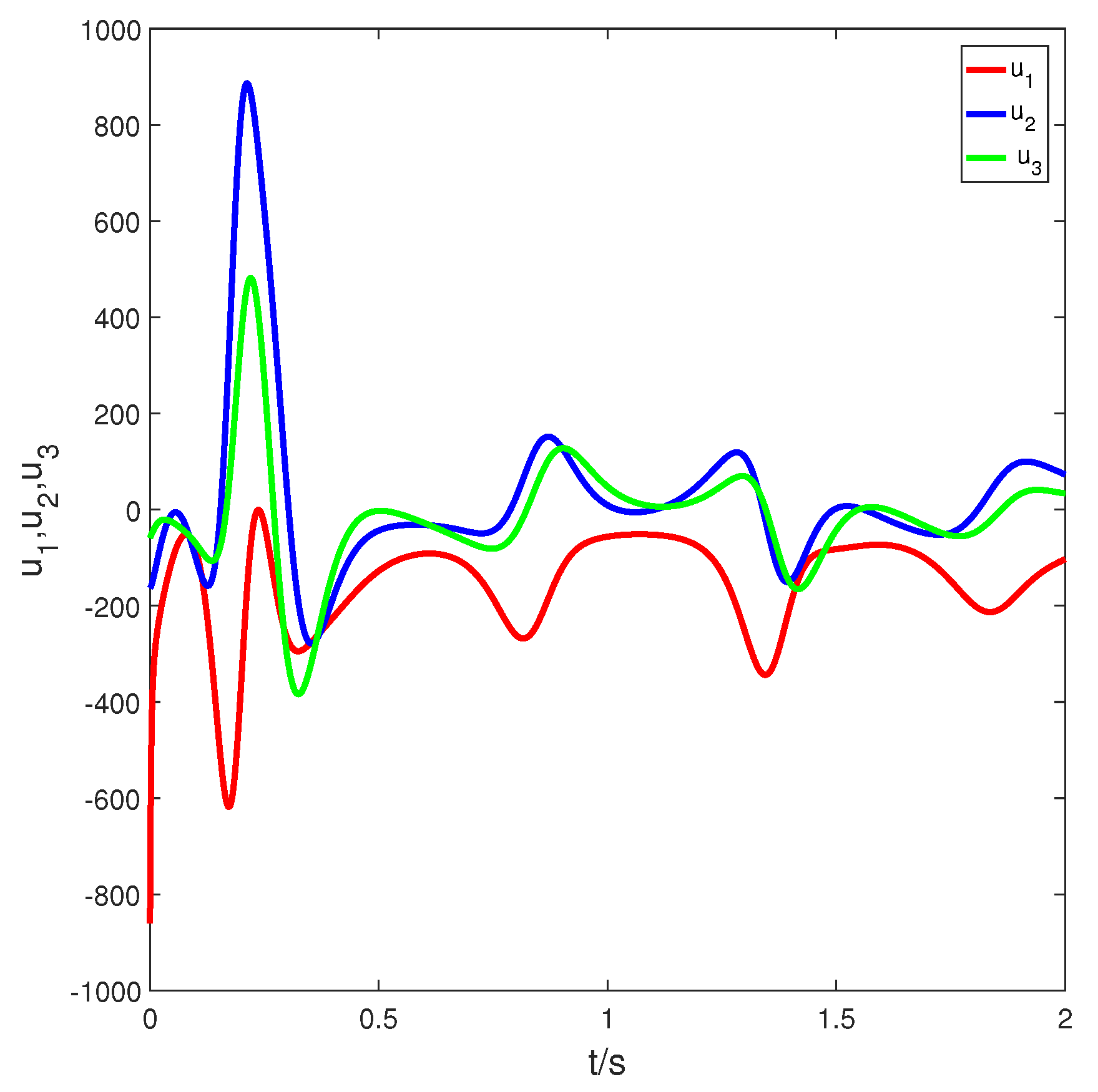
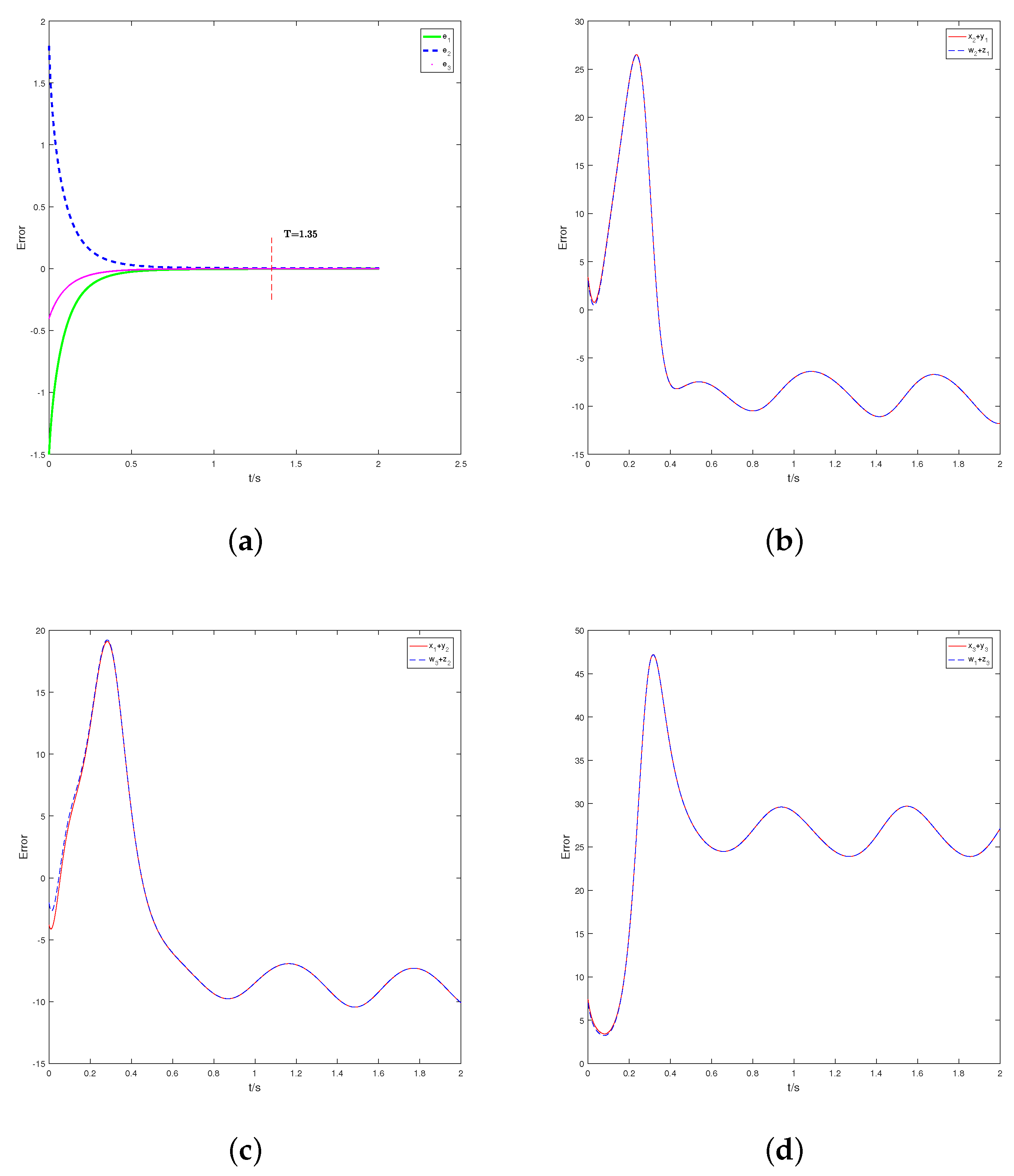
Finally, we further prove our conclusion using a numerical simulation. Let N = d i a g ( 1 , 1 , 1 ) , P = d i a g ( 1 , 1 , 1 ) , R = d i a g ( 1 , 1 , 1 ) and Q = d i a g ( 1 , 1 , 1 ) and the fractional-order β = 0.9 . The initial states of the drive and response systems are arbitrarily chosen as ( x 1 ( 0 ) , x 2 ( 0 ) , x 3 ( 0 ) ) = ( 3 , 1 , 2 ) , ( y 1 ( 0 ) , y 2 ( 0 ) , y 3 ( 0 ) ) = ( 2 , 5 , 5 ) , ( w 1 ( 0 ) , w 2 ( 0 ) , w 3 ( 0 ) ) = ( 3 , 2 , 2 ) , ( z 1 ( 0 ) , z 2 ( 0 ) , z 3 ( 0 ) ) = ( 1 , 3 , 6.5 ) . We choose the switch surface and controller parameters as μ 1 = μ 3 = 11 / 9 , μ 2 = μ 4 = 5 / 9 and σ 1 = σ 2 = η 1 = η 2 = 10 . Additionally, k i = [ 3 , 3 , 3 ] T , where k i k i Δ f + k i Δ g + k i Δ r + k i Δ h + k i d f + k i d g + k i d r + k i d h . According to (35), we find the maximum synchronization time T < 1.35 . When there are uncertainties and external disturbances on Switch 1, the synchronization time and error vectors of the two systems are as shown in Figure 1. The control input of Switch 1 is shown in Figure 2. When there are uncertainties and external disturbances on Switch 2, the synchronization time and error vectors of the two systems are as shown in Figure 3. The control input of Switch 2 is shown in Figure 4.

5. Conclusions

This paper extends fixed time to multi-switch combination–combination synchronization. This method not only ensures that the transmitted signal has stronger anti-attack and anti-translation abilities than a signal transmitted by a single transmitter, but also ensures that the signal transmission is completed in a limited time. It can be concluded that this method is very pragmatic in practical application. Aiming at four fractional-order chaotic systems with uncertainty and external disturbance, an appropriate controller and sliding mode surface are designed to realize the fixed-time multi-switch combination–combinatorial synchronization of fractional-order chaotic systems. It is worth mentioning that the defined sliding surface not only guarantees the stability of the fixed time, but also the upper bound of the synchronization time is independent of differences in the initial conditions of the master–slave system, and depends only on the design parameters. Two switches are selected for numerical simulation, and the effectiveness and robustness of the proposed method are verified. This method can further be applied to studies considering the case of parameter uncertainty, and can also be extended to more synchronization mechanisms or complex network synchronization.

Author Contributions

D.L. proposed the main idea and initially prepared the manuscript. T.L. supplied the numerical simulation of this paper. X.H. revised the English grammar of this paper. All authors have read and agreed to the published version of the manuscript.

Funding

This work is partly supported by Project of the Science and Technology Department in Sichuan Province (Grant No. 2021ZYD0004), Fund of Sichuan University of Science and Engineering (Grant No. 2022RC12), Sichuan Key Provincial Research Base of Intelligent Tourism (Grant No. ZHYR20-02), The Postgraduate Innovation Fund Project of Sichuan University of Science and Engineering (Grant No. y2021102).

Institutional Review Board Statement

Not applicable.

Informed Consent Statement

Not applicable.

Data Availability Statement

The data used to support the findings of this study are available from the corresponding author upon request.

Acknowledgments

Here, I would like to thank my instructor, Li Tianzeng. It was Teacher Li’s careful guidance that allowed me to successfully complete the research work.

Conflicts of Interest

The authors declare that they have no competing interest.

Abbreviations

The following abbreviations are used in this manuscript:
FTMSCCSFixed time multi-switch combination–combination synchronization
MSCCSMulti-switching combination–combination synchronization

References

  1. Lorentz, E.N. Deterministic non-periodic flows. J. Atmos. Sci. 1963, 20, 130–141. [Google Scholar] [CrossRef]
  2. Ueta, T.; Chen, G. Bifurcation analysis of Chen’s equation. Int. J. Bifurc. Chaos Appl. Sci. Eng. 2000, 10, 1917. [Google Scholar] [CrossRef]
  3. Jing, Z.J.; Yu, C.; Chen, G.R. Complex dynamics in a permanent-magnet synchronous motor model. Chaos Solitons Fractals 2004, 22, 831–848. [Google Scholar] [CrossRef]
  4. Pecora, L.M.; Carroll, T.L. Synchronization in chaotic systems. Phys. Rev. Lett. 1990, 64, 821–824. [Google Scholar] [CrossRef] [PubMed]
  5. Li, K.Z.; Zhao, M.C.; Fu, X.C. Projective synchronization of driving–response systems and its application to secure communication. IEEE Trans. Circuits Syst. Regul. Pap. 2009, 56, 2280–2291. [Google Scholar]
  6. Wu, X.J.; Lu, Y. Generalized projective synchronization of the fractional-order Chen hyperchaotic system. Nonlinear Dyn. 2009, 57, 25–35. [Google Scholar] [CrossRef]
  7. Zhu, Z.Y.; Zhao, Z.S.; Zhang, J.; Wang, R.K.; Li, Z.Q. Adaptive fuzzy control design for synchronization of chaotic time-delay system. Inf. Sci. 2020, 535, 225–241. [Google Scholar] [CrossRef]
  8. Liu, H.; Li, S.G.; Wang, H.X.; Li, G.J. Adaptive fuzzy synchronization for a class of fractional-order neural networks. Chin. Phys. B 2017, 26, 262–271. [Google Scholar] [CrossRef]
  9. Hu, M.F.; Xu, Z.Y. Adaptive feedback controller for projective synchronization. Nonlinear Anal. Real World Appl. 2008, 9, 1253–1260. [Google Scholar] [CrossRef]
  10. Pemen, A.J.M.; Heesch, E.J.M.V.; Zhen, L. Synchronous pulse systems. IEEE Trans. Plasma Sci. 2012, 40, 1198–1204. [Google Scholar] [CrossRef]
  11. Qiao, Z.W.; Shi, T.N.; Wang, Y.D.; Yan, Y.; Xia, C.L.; He, X.N. New sliding-mode observer for position sensorless control of permanent-magnet synchronous motor. IEEE Trans. Ind. Electron. 2013, 60, 710–719. [Google Scholar] [CrossRef]
  12. Cao, Y.; Nikan, O.; Avazzadeh, Z. A localized meshless technique for solving 2D nonlinear integro-differential equation with multi-term kernels. Appl. Numer. Math. 2023, 183, 140–156. [Google Scholar] [CrossRef]
  13. Wang, Q.; Qi, D.L. Synchronization for fractional order chaotic systems with uncertain parameters. Int. J. Control. Autom. Syst. 2016, 14, 211–216. [Google Scholar] [CrossRef]
  14. Huang, C.D.; Cao, J.D. Active control strategy for synchronization and anti-synchronization of a fractional chaotic financial system. Phys. Stat. Mech. Its Appl. 2017, 473, 262–275. [Google Scholar] [CrossRef]
  15. Mohammadzadeh, A.; Ghaemi, S. Robust synchronization of uncertain fractional-order chaotic systems with time-varying delay. Nonlinear Dyn. 2018, 93, 1809–1821. [Google Scholar] [CrossRef]
  16. Zhang, X.; Wu, R.C. Modified projective synchronization of fractional-order chaotic systems with different dimensions. Acta Math. Appl. Sin. Engl. Ser. 2020, 36, 527–538. [Google Scholar] [CrossRef]
  17. Haris, M.; Shafiq, M.; Ibrahim, A.; Misiran, M. Nonlinear feedback controller for the synchronization of hyper (Chaotic) systems with known parameters. J. Math. Comput. Sci. 2020, 23, 124–135. [Google Scholar] [CrossRef]
  18. Ababneh, O.Y. Adaptive synchronization and anti-synchronization of fractional order chaotic optical systems with uncertain parameters. J. Math. Comput. Sci. 2021, 23, 302–314. [Google Scholar] [CrossRef]
  19. Li, X.G.; Rao, R.F.; Zhong, S.M.; Yang, X.S.; Li, H.; Zhang, Y.L. Impulsive control and synchronization for fractional-order hyper-chaotic financial system. Mathematics 2022, 10, 2737. [Google Scholar] [CrossRef]
  20. Polyakov, A. Nonlinear feedback design for fixed-time stabilization of linear control systems. IEEE Trans. Autom. Control 2012, 57, 2106–2110. [Google Scholar] [CrossRef] [Green Version]
  21. Ni, J.K.; Liu, L.; Liu, C.X.; Hu, X.Y. Fractional order fixed-time nonsingular terminal sliding mode synchronization and control of fractional order chaotic systems. Nonlinear Dyn. 2017, 89, 2065–2083. [Google Scholar] [CrossRef]
  22. Shirkavand, M.; Pourgholi, M. Robust fixed-time synchronization of fractional order chaotic using free chattering nonsingular adaptive fractional sliding mode controller design. Chaos Solitons Fractals 2018, 113, 135–147. [Google Scholar] [CrossRef]
  23. Yao, Q.J. Synchronization of second-order chaotic systems with uncertainties and disturbances using fixed-time adaptive sliding mode control. Chaos Solitons Fractals 2021, 142, 110372. [Google Scholar] [CrossRef]
  24. Shirkavand, M.; Pourgholi, M.; Yazdizadeh, A. Robust global fixed-time synchronization of different dimensions fractional-order chaotic systems. Chaos Solitons Fractals 2022, 154, 11616. [Google Scholar] [CrossRef]
  25. Almatroud, A.O.; Ababneh, O.; Al-Sawalha, M.M. Modify adaptive combined synchronization of fractional order chaotic systems with fully unknown parameters. J. Math. Comput. Sci. 2020, 21, 99–112. [Google Scholar] [CrossRef]
  26. Zhou, L.L.; Wang, C.H.; Lin, Y.; He, H.Z. Combinatorial synchronization of complex multiple networks with unknown parameters. Nonlinear Dyn. 2015, 79, 307–324. [Google Scholar] [CrossRef]
  27. Kaviarasan, B.; Kwon, O.M.; Park, M.J.; Sakthivel, R. Composite synchronization control for delayed coupling complex dynamical networks via a disturbance observer-based method. Nonlinear Dyn. 2020, 99, 1601–1619. [Google Scholar] [CrossRef]
  28. Zhang, B.; Deng, F.Q. Double-compound synchronization of six memristor-based Lorenz systems. Nonlinear Dyn. 2014, 77, 1519–1530. [Google Scholar] [CrossRef]
  29. Ucar, A.; Lonngren, K.E.; Bai, E.W. Multi-switching synchronization of chaotic systems with active controllers. Chaos Solitons Fractals 2008, 38, 254–262. [Google Scholar] [CrossRef]
  30. Wang, X.Y.; Sun, P. Multi-switching synchronization of chaotic system with adaptive controllers and unknown parameters. Nonlinear Dyn. 2011, 63, 599–609. [Google Scholar] [CrossRef]
  31. Vincent, U.E.; Saseyi, A.O.; McClintock, P.V.E. Multi-switching combination synchronization of chaotic systems. Nonlinear Dyn. 2015, 80, 845–854. [Google Scholar] [CrossRef] [Green Version]
  32. Zheng, S. Multi-switching combination synchronization of three different chaotic systems via nonlinear control. Opt. Z. Fur-Licht-Und Elektron. J. Light-Electronoptic 2016, 127, 10247–10258. [Google Scholar] [CrossRef]
  33. Song, S.; Song, X.N.; Pathak, N.; Balsera, I.T. Multi-switching adaptive synchronization of two fractional-order chaotic systems with different structure and different order. Int. J. Control. Autom. Syst. 2017, 15, 1524–1535. [Google Scholar] [CrossRef]
  34. Khan, A.; Bhat, A.A. Multi-switching combination–combination synchronization of non-identical fractional-order chaotic systems. Math. Methods Appl. Sci. 2017, 40, 5654–5667. [Google Scholar] [CrossRef]
  35. Zhang, H.; Wang, X.Y.; Zhang, J.; Yan, P.F. Multi-switching combination synchronization of spatiotemporal coupled chaotic systems with complexities. Int. J. Mod. Phys. Comput. Phys. Phys. Comput. 2019, 30, 1950067. [Google Scholar] [CrossRef]
  36. Shafiq, M.; Ahmad, I. Multi-Switching combination anti-synchronization of unknown hyperchaotic systems. Arab. J. Sci. Eng. 2019, 44, 7335–7350. [Google Scholar] [CrossRef]
  37. Muhammad, S.; Israr, A.; Ambusaidi, M.A.; Bashir, N. Robust adaptive multi-switching synchronization of multiple different orders unknown chaotic systems. J. Syst. Sci. Complex. 2020, 33, 1330–1359. [Google Scholar] [CrossRef]
  38. Pan, W.Q.; Li, T.Z.; Sajid, M.; Ali, S.; Pu, L.P. Parameter identification and the finite-time combination–combination synchronization of fractional-order chaotic systems with different structures under multiple stochastic disturbances. Mathematics 2022, 10, 712. [Google Scholar] [CrossRef]
  39. Podlubny, I. Fractional Differential Equations; Elsevier Science and Technology: Amsterdam, The Netherlands, 1998. [Google Scholar]
  40. Aguila-Camacho, N.; Duarte-Mermoud, M.A.; Gallegos, J.A. Lyapunov functions for fractional order systems. Commun. Nonlinear Sci. Numer. Simul. 2014, 19, 2951–2957. [Google Scholar] [CrossRef]
  41. Li, Y.; Chen, Y.Q.; Podlubny, I. Stability of fractional-order nonlinear dynamic systems: Lyapunov direct method and generalized Mittag-Leffler stability. Comput. Math. Appl. 2009, 59, 1810–1821. [Google Scholar] [CrossRef] [Green Version]
  42. Zuo, Z.; Tie, L. Distributed robust finite-time nonlinear consensus protocols for multi-agent systems. Int. J. Syst. Sci. 2016, 47, 1366–1375. [Google Scholar] [CrossRef]
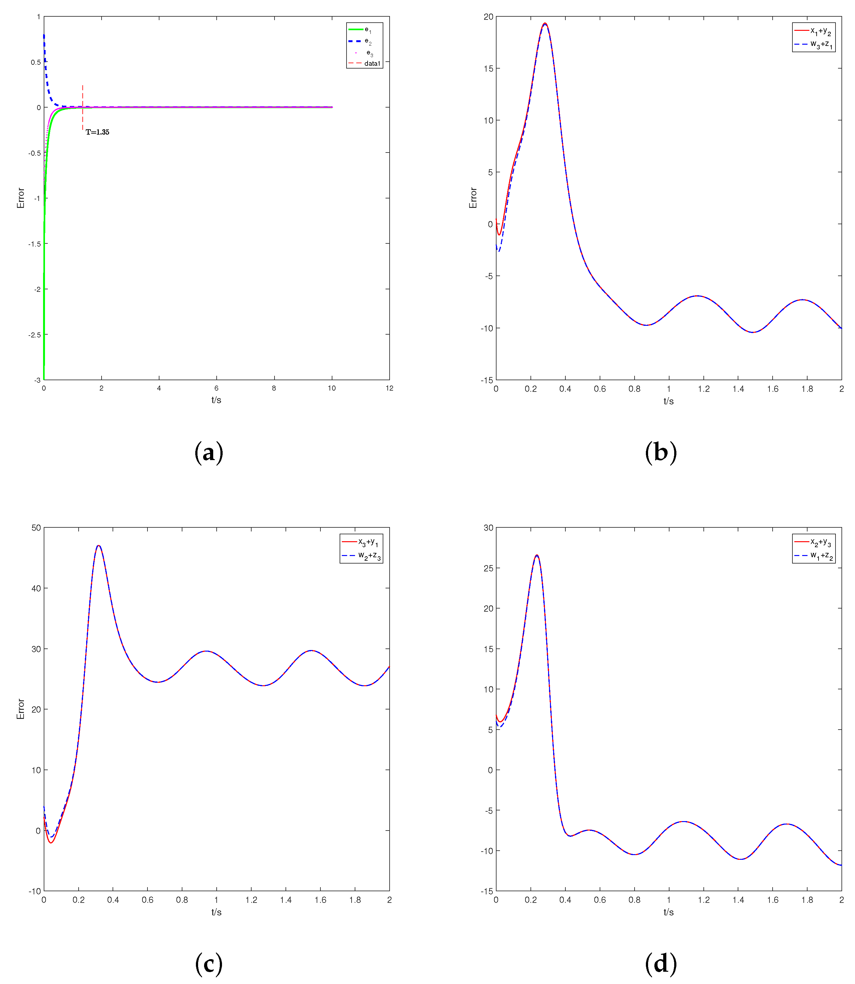
Figure 1. (a): The time response of synchronization error of Switch 1, (bd): The state trajectories of Switch 1.
Fractalfract 07 00281 g001
Figure 2. Switch 1 control input of error system.
Fractalfract 07 00281 g002
Figure 3. (a): The time response of synchronization error of Switch 2, (bd): The state trajectories of Switch 2.
Fractalfract 07 00281 g003
Figure 4. Switch 2 control input of error system.
Fractalfract 07 00281 g004
Disclaimer/Publisher’s Note: The statements, opinions and data contained in all publications are solely those of the individual author(s) and contributor(s) and not of MDPI and/or the editor(s). MDPI and/or the editor(s) disclaim responsibility for any injury to people or property resulting from any ideas, methods, instructions or products referred to in the content.