Abstract
This paper proposes an active disturbance rejection control (ADRC) architecture for a permanent magnet synchronous motor (PMSM) position servo system. The presented method achieved enhanced tracking and disturbance rejection performance with a limited observer bandwidth. The model-aided extended state observer (MESO)-based ADRC was designed for the current, speed, and position loops of the PMSM position servo system. By integrating known plant information, the MESO improved disturbance estimation with a limited observer bandwidth without amplifying the noise. Additionally, a fractional-order proportional-derivative (FOPD) controller was designed as the feedback controller for the speed loop to further enhance the disturbance rejection. A simulation and experimental tests were conducted on a PMSM servo platform. The results demonstrate not only that the proposed method achieved superior tracking performance but also that the position error of the proposed strategy decreases to 2.25% when the constant disturbance was input, significantly improving the disturbance rejection performance.
1. Introduction
Permanent magnet synchronous motors (PMSMs) have gained widespread use in industrial applications [1]. However, the existence of nonlinearities, uncertainties, and disturbances [2] makes it challenging for a conventional proportional–integral (PI) control strategy to achieve high-precision control for the PMSM servo system [3,4]. In recent years, diverse control strategies have been developed for PMSM, aiming to enhance control effectiveness. Active disturbance rejection control (ADRC) is one of the most popular control strategies.
Proposed in the 1980s by Jingqing Han [5], ADRC was designed to address extensive uncertainties and disturbances. The fundamental concept of ADRC involves treating external disturbances and internal uncertainties collectively as the “total disturbance”, which is then estimated using the extended state observer (ESO) and actively compensated for via the ESO-based feedback controller. Despite its theoretical soundness, the intricate nonlinear structure and intricate tuning process have rendered its practical application challenging. A linear version (LADRC) and bandwidth parameterization proposed by Zhiqiang Gao have greatly simplified the structures and tuning of ADRC [6]. As a result, ADRC can be quickly applied in various industrial areas, such as wind turbines [7], robot control [8], aerial vehicles [9,10], motor control [11], and so on. In recent years, the field of ADRC has undergone substantial growth.
LADRC possesses various superior properties, including a compact structure, model independence, superior disturbance rejection, and robustness [12,13]. However, there are still some challenges that necessitate additional research:
- A high observer bandwidth is required to achieve the desired disturbance estimation and rejection [6], but the high observer bandwidth will amplify the measurement noise [14].
- The LESO and the feedback controller are mutually coupled, while the tracking performance cannot be completely separated from the LESO [15,16].
- The design of LADRC based on the bandwidth parameterization method is relatively conservative, potentially leading to suboptimal control performance [17].
Various versions of ADRC have been proposed to tackle these challenges. Some studies designed ADRC to incorporate the known plant information to improve the disturbance rejection performance. For instance, the ADRC strategy with a generalized extended sta observer (GESO) was presented in [17,18,19], where the known plant information was incorporated into the ESO. With a GESO, ADRC shows improved control capability on non-minimum-phase, unstable, and time-delay systems. Another benefit of GESO-based ADRC demonstrated in [16] is that it satisfies the separation principle, meaning that the feedback controller design is separated from a GESO. Ref. [20] applied the ADRC with a model-aided ESO (MESO) in the current control of a PMSM, obtaining enhanced parameter robustness performance. Some studies have modified the structure of ADRC to improve the control performance. Ref. [14] presented an improved ESO to suppress the measurement noise. Recently, some intelligent algorithms have been applied in ADRC. Ref. [21] applied a diagonal recurrent neural network in ADRC for the radar position servo system facing a dead zone and friction nonlinearities. Ref. [22] introduced an ADRC method based on the deep reinforcement learning algorithm for more electric aircraft. Ref. [23] presented an optimal ADRC based on a proportional-derivative (PD) control law with particle swarm optimization to improve the dynamic and steady-state control performance.
In recent developments, integrating ADRC with fractional-order control (FOC) has garnered attention to enhance control performance. FOC is the extension of traditional integer-order control, providing more flexibility in controller design and improved control performance [24]. An application of fractional-order ADRC (FOADRC) was presented for a linear motor to achieve precise tracking performance [25]. Ref. [16] proposed an FOADRC controller with GESO to improve tracking and disturbance rejection performance for a PMSM servo system. The design of FOADRC with fractional-order ESO was investigated in [26] to suppress noise sensitivity. Ref. [27] proposed a fractional-order ESO-based ADRC method to address the trade-off between control performance and noise suppression. Ref. [28] presented a fractional-order ADRC method incorporating the fuzzy self-tuning method, which achieved an improved dynamic response and disturbance suppression capability. Ref. [29] proposed an optimal fractional-order ADRC method for the PMSM speed servo system, which met the requirement for frequency-domain indicators and achieved optimal performance in the time domain. A comparison of these versions of ADRC is presented in Table 1.

Table 1.
Comparison of different versions of ADRC.
The primary objective of this paper is to improve the disturbance rejection performance with an observer bandwidth limitation for the PMSM position servo system, integrating the benefits of the model-aided ADRC and fractional-order control. The primary contributions of this paper are summarized as follows:
- (1)
- An MESO-based ADRC architecture is introduced for the PMSM position servo system, demonstrating improved tracking and disturbance rejection under limited observer bandwidth.
- (2)
- The MESO-based ADRC was designed for the current, speed, and position loops. Additionally, a fractional-order feedback controller was designed for the speed loop, further enhancing the disturbance rejection performance on the basis of the MESO.
- (3)
- Simulation and experimental comparison tests on a PMSM position servo system were conducted to verify the effectiveness of the proposed method.
The subsequent sections of this paper are organized as follows: In Section 2, the MESO-based ADRC is presented. Section 3 covers the design and tuning of the cascade ADRC strategy for the PMSM position servo system. Simulation comparisons and a discussion are presented in Section 4. Section 5 presents experimental verification. Finally, Section 6 presents the conclusion of this paper.
2. The Principle of MESO-Based ADRC
Figure 1 illustrates the structure of the MESO-based ADRC. It comprises an MESO and a feedback controller. The controlled plant is an n-th order system. The MESO estimates the lumped disturbance and plant states in real time. The feedback controller and MESO collaborate to generate the control effort. The specific details of the MESO-based ADRC are described below.
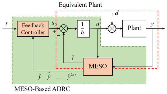
Figure 1.
Block diagram of MESO-based ADRC.
2.1. MESO-Based ADRC
Consider an n-th order plant:
where y, u, and d are the plant’s output, input, and external disturbance, respectively; n is the order of the plant, and and b are the plant coefficients. Its transfer function model is
Let f represent the lumped disturbance as
the plant (1) is converted to
The lumped disturbance f encompasses the known dynamics of the controlled plant and the unknown external disturbance.
When f is taken as an augmented state and , is defined (assuming d is differentiable), the plant (4) is represented as augmented state-space form:
where
The MESO can be designed based on Equation (5) as
where is the estimation of x, is the estimation of y, and L is the observer gain vector,
Remark 1.
The distinction between an MESO and an LESO lies in an MESO’s utilization of all known plant information, while an LESO does not incorporate this information. The GESO proposed in [17] also utilizes known plant information, but it does not consider the known plant dynamics as part of the lumped disturbance f defined in the GESO. The GESO’s disturbance compensation cannot transform the controlled plant into the ideal cascade integral plant. In contrast, an MESO can achieve cascade-integral plant equivalence because the known plant dynamics are considered as part of the lumped disturbance f in the MESO.
The control effort is generated for the combination of the estimated disturbance and the output of the feedback controller in real time, which is represented as
Substitute it in (4), and the plant (1) is equivalent to
If the MESO is designed appropriately, completely compensates for the effects of the lumped disturbance f. Thus, the controlled plant is equivalent to an nth-order integrator plant. The state-feedback control law is designed as
In summary, the MESO-based ADRC can be expressed as
where , , and .
2.2. Parameter Tuning
From (11), the MESO-based ADRC has two sets of gains to tune: the observer gain L and the state-feedback gain K. Many different methods can be utilized to tune L and K. The idea of the bandwidth parameterization method places all the poles of the ESO and the closed-loop system at and [6]. and are considered the bandwidths of the MESO and the closed-loop system.
Therefore, the characteristic equation of the MESO can be obtained using
The value of for L can be solved by comparing the coefficients of the two sides of (12).
Substitute (10) in (9), and the closed-loop system can be represented as
The characteristic equation of (13) can be expressed as
The value of for can be solved from (14) as
Generally, the observer’s response is faster than the closed-loop system’s. Therefore, should be larger than , and an appropriate choice is .
Remark 2.
The bandwidth parameterization method, while relatively conservative, facilitates the achievement of a non-overshoot response in the closed-loop system for setpoint tracking. In certain scenarios, there might be a need for a faster response. To address this, alternative tuning methods, including frequency specifications, loop shaping, and optimization, can be employed to attain the desired response. Moreover, various control laws, including PID, sliding mode control, and fractional-order control, can be implemented.
2.3. Transfer Function Derivation
The MESO-based ADRC can be equivalent to a two-degrees-of-freedom closed-loop system, as shown in Figure 2, where is the setpoint filter, and is the feedback controller [30]. They can be obtained from the Laplace transform of (11) as follows:
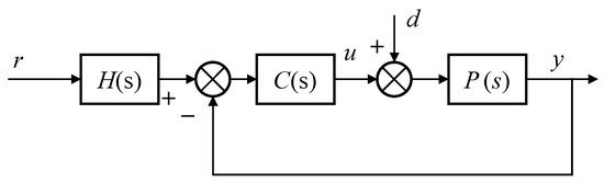
Figure 2.
The transfer function form of the MESO-based ADRC.
From Figure 2, the transfer function from r to y is derived as follows:
It is used to derive the transfer function of the closed-loop system . If is allowed, is converted to the equivalent plant .
The external disturbance transfer function from d to y can be expressed as
It is used to analyze the disturbance rejection performance of the closed-loop system.
3. Cascade ADRC Strategy for a PMSM Position Servo System
The block diagram of the cascade ADRC for the PMSM position servo system is shown in Figure 3. There are three loops for the PMSM position servo system, i.e., current, speed, and position loops. The modeling of the PMSM and the MESO-based ADRC design for each loop is subsequently introduced.
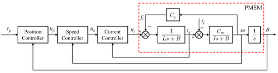
Figure 3.
The structure of the cascade ADRC for a PMSM position servo system.
3.1. Modeling of PMSM
The voltage equations for a surface-mounted PMSM in d–q coordinates are expressed as follows:
where , , , and represent the stator voltages and currents of the d- and q-axes, respectively; denotes the stator inductance, is the stator resistance, signifies the angular velocity, is the number of pole pairs, and stands for the rotor flux linkage.
The current reference of the d-axis is used to decouple the stator voltages and currents. Thus, the voltage equation represented by (20) is simplified to
where is the induced voltage constant.
The motion equation of the PMSM can be expressed as follows:
where J is the moment of inertia, is the torque coefficient, is the load torque, is the viscous friction coefficient, and is the mechanical angle of the rotor.
3.2. Current Loop Design
Taking the EMF as part of the lumped disturbance, the controlled plant for the current loop is , as in (23). According to (11), a first-order MESO-based ADRC can be designed for the current loop with and .
The bandwidth parameterization method is adopted for the current loop. Given the observer bandwidth , the observer gain is calculated using (12) as follows:
Given the controller bandwidth , the state feedback gain can be obtained using (14) as follows:
The current closed loop can be obtained via (18) as follows:
3.3. Speed Loop Design
The plant for the speed loop consists of the current closed loop (28) and the speed motion part (24), which can be represented as
where , , and .
The MESO for the speed loop can be designed based on (29). Given the observer bandwidth , the observer gain can be obtained via (12) as follows:
The equivalent plant for the speed loop can be obtained via (18) as follows:
Remark 3.
The equivalent plant is an ideal double-integrator plant equivalence, which means is independent of the MESO. The design of the feedback controller is entirely decoupled from the MESO. This characteristic is also preserved in the designed ADRC for current and position loops based on the MESO. This separation enables the independent adjustment of disturbance rejection performance via the MESO without impacting the setpoint tracking determined according to the feedback controller. In contrast, the traditional LESO does not possess this property, as the equivalent plant using the LESO is always coupled with the LESO.
A fractional-order PD (FOPD) controller was designed as the feedback controller, which can be expressed as follows:
where represents the fractional-order differential, and the order of the derivative is . The Caputo definition of the fractional-order derivative was adopted in this paper. The nominal control system of the speed loop is shown in Figure 4. The parameters of FOPD were designed based on this nominal control system.
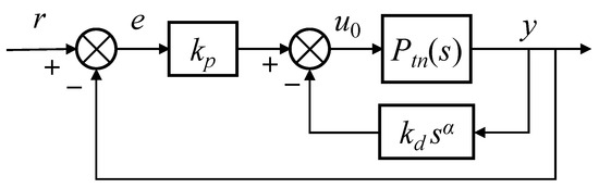
Figure 4.
The nominal control system of the speed loop.
Per Figure 4, the open-loop transfer function is
There is a fractional-order integrator in (33), and should satisfy to ensure the steady-state error. Given the gain crossover frequency and phase margin , the equations can be obtained as follows:
Given a specific , the parameters of and for (32) can be obtained as follows:
The choice of is bounded as for a specific phase margin, . The choice of is a trade-off between disturbance rejection and noise suppression.
The complementary sensitivity function of the nominal control system is
It is also the closed-loop transfer function of the nominal control system. The noise suppression specification defined by determines the value of , which is represented as
where
Given the frequency , is calculated using (37) and (35) by sweeping in . Then, is obtained from the curve of with reference to satisfying the gain limit of dB. A flow chart of the design procedure for the speed loop is presented in Figure 5.
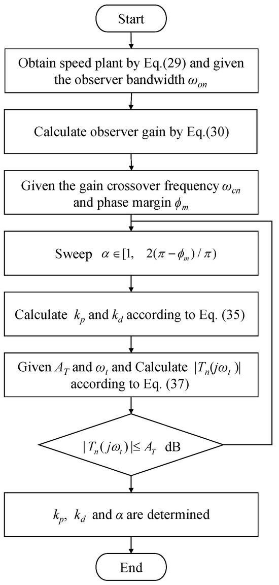
Figure 5.
Flow chart of the design procedure for the speed loop.
3.4. Position Loop Design
Neglecting the fractional order, the designed speed closed-loop was approximated as an integer-order system. The difference in order was treated as part of the lumped disturbance. Therefore, according to (38) and (25), the controlled plant of the position loop can be represented as
where , , , and .
The MESO for the position loop can be designed based on (39), according to (5) and (6). Given the observer bandwidth , the observer gain can be obtained using (12) as follows:
The bandwidth parameterization method was used to tune the feedback controller for the position loop. Placing all the poles of the closed loop at allowed the parameter’s value to be solved from (14) as follows:
4. Simulation and Discussion
The mathematical models of the experimental PMSM were identified as
Such a PMSM device was used for the subsequent simulation and analysis.
Three control strategies are presented for comparison: the traditional LESO-based ADRC [6], the proposed MESO-based ADRC with a PD feedback controller, and the proposed MESO-based ADRC with an FOPD feedback controller. The control strategies designed for comparison are listed in Table 2.
Table 2.
Control strategies designed for comparison.
4.1. Current Loop
The plant parameters can be determined as and via (42). Given rad/s and rad/s, the parameters of the MESO-based ADRC for the current loop can be designed as , , and . The parameters designed for the LESO-based ADRC are , , and .
4.2. Speed Loop
The controlled plant of the speed loop is represented by (29), with , , and . The design specifications for the speed loop included rad/s, rad/s, , rad/s, and dB. Subsequently, the MESO for the speed loop could be designed.
Considering , the fractional order bound for FOPD can be calculated as . By sweeping within this range, the parameters and can be determined using (35). The parameter curve for FOPD is illustrated in Figure 6a. As approaches its upper bound, increases rapidly. The gain of at can be calculated using (37). The curve of with respect to is depicted in Figure 6b. It indicates that the gain in increases with a rising , leading to a gradual decrease in the noise suppression ability. For , the constraint in (37) is satisfied. Hence, was selected to achieve better disturbance rejection performance.
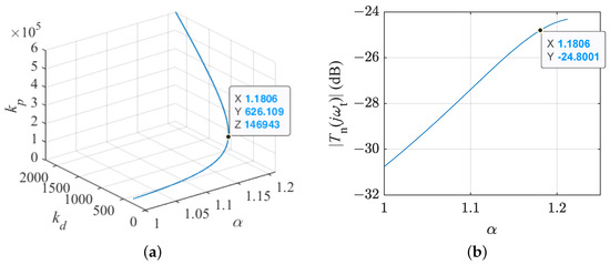
Figure 6.
Curves for FOPD design: (a) parameters curve; (b) w.r.t. .
The PD-LESO and PD-MESO controllers were also designed for comparison using the same design specifications. The parameters of the design controllers for the speed loop are shown in Table 3.
Table 3.
Parameters of the designed controllers for the speed loop.
(1) Disturbance rejection and noise suppression for the ESO: When the estimation error is defined as , the dynamics of the estimation error can be obtained using (5) and (6) as follows:
where n is the sensor noise. By applying the Laplace transform to (44), the transfer function from d to () can be obtained as follows:
The transfer function from n to can be derived as follows:
where . and are used to evaluate the MESO’s disturbance rejection and noise sensitivity, respectively. Therefore, and for the speed loop can be obtained as follows:
The Bode plots of and are depicted in Figure 7a,b. With the same observer bandwidth , Figure 7 illustrates that the MESO exhibits superior disturbance estimation performance compared to the LESO, while both maintain the same noise suppression performance. The disturbance estimation performance of the LESO improves as increases, but the noise suppression performance decreases simultaneously.
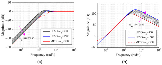
Figure 7.
Frequency responses comparison of a different ESO for the speed loop: (a) disturbance estimation; (b) noise suppression.
Remark 4.
Since the MESO incorporates the plant information as the known part of the total disturbance, the burden of MESO tracking f is lower compared to the traditional LESO. It is well known that the selection of observer bandwidth involves a trade-off between disturbance estimation and noise sensitivity. Therefore, the MESO alleviates this conflict and achieves better disturbance estimation and noise suppression performance simultaneously compared to the LESO under a limited observer bandwidth.
(2) The equivalent plant: The Bode plots of the equivalent plant are presented in Figure 8. It shows that the MESO-based equivalent plant is identical to the nominal plant, represented as . However, the LESO-based equivalent plant differs significantly from the nominal plant. Although the differences between the equivalent plant and the nominal plant decrease as increases, the LESO becomes more sensitive to noise at a high .
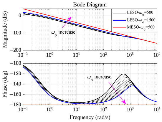
Figure 8.
Bode plots of the equivalent plant for the speed loop.
(3) Open-loop Bode plots: Open-loop Bode plots are illustrated in Figure 9a. It is evident from the plots that the designed PD-MESO and FOPD-MESO met the design specifications, whereas the PD-LESO did not. Due to the significant difference between the LESO-based equivalent plant and the nominal plant, the designed PD feedback controller based on the nominal plant could not meet the design specifications in the real system. In the case of the FOPD-MESO, the gain at the low-frequency range increased with a rising , leading to an improvement in the steady-state error. However, simultaneously, the gain in the high-frequency range also increased with a rising , indicating a decrease in noise suppression performance.
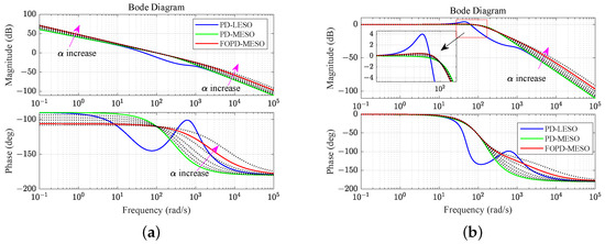
Figure 9.
Bode plots of the transfer functions for the speed loop: (a) the open loop; (b) the closed loop.
(4) Closed-loop Bode plots: The closed-loop transfer function is identical to the complementary sensitivity function, as per (38) and (36). The Bode plots are depicted in Figure 9b. It is observed that the PD-MESO exhibited the lowest resonance peak. The resonance peak of the PD-LESO was notably higher than that of the other controllers. The resonance peak of the FOPD-MESO increased with a rising , accompanied by an increase in the gain in the high-frequency range. The relative stability and noise suppression of the FOPD-MESO decreased as increased.
(5) The disturbance rejection of the closed loop: According to (19), the disturbance transfer function of the speed loop is
Bode plots of the disturbance transfer function are presented in Figure 10. It is evident that the MESO-based ADRC exhibited superior disturbance rejection performance compared to the other controllers. Moreover, the disturbance rejection performance of the FOPD-MESO improved with an increasing . Therefore, in addition to the MESO, the FOPD-MESO can enhance the disturbance rejection performance by adjusting . The choice of involves a trade-off between disturbance rejection and noise suppression.
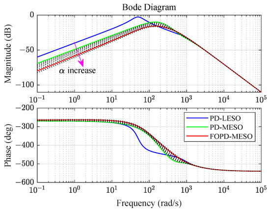
Figure 10.
Bode plots of the disturbance transfer function for the speed loop.
(6) The disturbance rejection tuning with and : Based on the analysis above, it can be concluded that the disturbance rejection performance of the FOPD-MESO can be simultaneously tuned by adjusting and . To explore this property, the step responses with disturbance for various and values are depicted in Figure 11a,b. Figure 11a demonstrates that the disturbance rejection performance improved as the value of increased, while the tracking performance remained unchanged. This verifies that the MESO-based ADRC satisfied the separation principle. The tracking performance was independent of the observer gain. Figure 11b illustrates that the disturbance rejection performance improved as increased. However, the overshoot of the setpoint tracking also increased simultaneously. Therefore, the FOPD provides another tunable parameter to enhance the disturbance rejection performance based on the MESO.
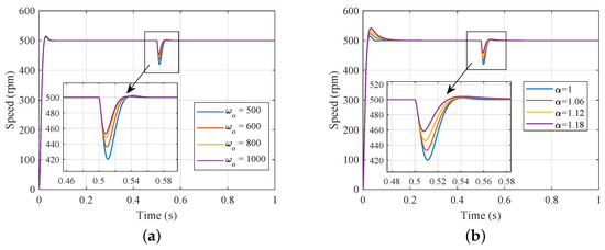
Figure 11.
The step response of the MESO-based ADRC for the speed loop (simulation): (a) different values (); (b) different values ( rad/s).
(7) Step response comparison for different control strategies: The step response of the speed loop is depicted in Figure 12. It is evident that the MESO-based ADRC exhibited superior tracking and disturbance rejection. The PD-LESO exhibited a worse transient response compared to the other controllers. When a disturbance was applied, the speed drop of the FOPD-MESO was 8.3%, significantly less than the PD-MESO’s 15.9%. Compared to the PD-MESO, the overshoot of the FOPD-MESO increased slightly from 3.0% to 8.4%. Therefore, the fractional order can be adjusted to balance tracking and disturbance rejection performance.
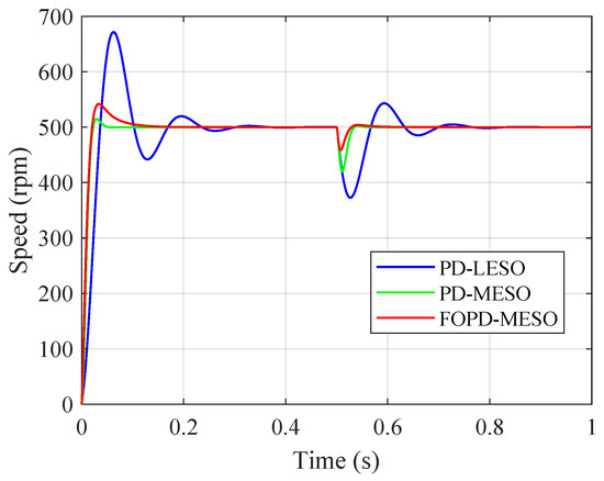
Figure 12.
The step response comparison for the speed loop (simulation).
4.3. Position Loop
The approximate plant of the position loop can be determined using (39), with 29,238.0, , 29,238.0, and . When the design specifications of the position loop are set as rad/s and rad/s, PD-MESO and PD-LESO can be designed based on this plant. The parameters of the design controllers for the position loop are presented in Table 4.
Table 4.
Parameters of the designed controllers for the position loop.
Figure 13 presents the step response of the position loop. It is evident that the LESO-based ADRC strategy exhibited a greater overshoot and position error when the disturbance was applied. This did not meet the design expectations, as the equivalent plant based on the LESO was significantly different from the nominal plant. However, the step response of the proposed MESO-based ADRC and FOC- and MESO-based ADRC could closely match the step response of the nominal system when using the same observer bandwidth. Additionally, the FOC- and MESO-based ADRC exhibited the smallest position error after disturbance input at 2.0%, compared to the MESO-based ADRC’s 4.5%. Therefore, the simulation indicated the best disturbance rejection performance of the FOC- and MESO-based ADRC compared with the other controllers.

Figure 13.
The step response comparison for the position loop (simulation).
5. Experimental Verification
5.1. Experimental Setup
Experimental validation was performed on a PMSM servo system, illustrated in Figure 14. The experimental setup consisted of essential components, including a PMSM, a servo drive, a DC generator, and a PC. The servo driver was powered via DSP-TMS320F28335. The structure of the PMSM position servo system based on field-oriented control is depicted in Figure 15. The control sampling frequencies for the current, speed, and position loops were 10 kHz, 5 kHz, and 2 kHz, respectively. The specifications of the PMSM are provided in detail in Table 5.
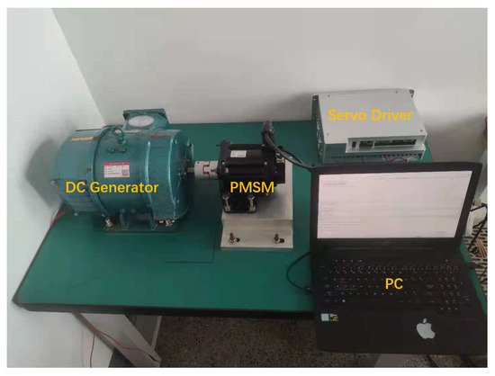
Figure 14.
The experimental PMSM position servo system.
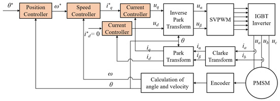
Figure 15.
The structure of the PMSM position servo system based on field-oriented control.
Table 5.
Specifications of the PMSM.
5.2. Experimental Tests for the Speed Loop
The fractional-order differential was approximated using a five-order discrete transfer function obtained through the impulse response invariant discretization method of [16]:
where
The Bode plot of the approximated is shown in Figure 16. It can be seen that the approximated fractional-order operator matched the true Bode plot of around rad/s, the gain crossover frequency of the speed loop, which means the approximated fractional-order ADRC could perform as the real fractional-order ADRC approximately.
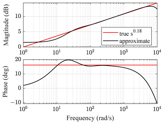
Figure 16.
The Bode plot comparison of approximated and true .
Figure 17a,b illustrates the step response of the PMSM’s speed loop with varying values of and . The experimental results validated the effectiveness of tuning disturbance rejection performance using and , as observed in the simulation. It was observed that the tracking performance remained unaffected by the MESO bandwidth, while the disturbance rejection performance improved with an increasing . Furthermore, the disturbance performance improved with an increasing , but it accompanied an increase in the overshoot.
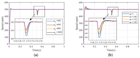
Figure 17.
The step response of the MESO-based ADRC for the speed loop (experiment): (a) different values (); (b) different values ( rad/s).
Figure 18 presents the step response of the PMSM’s speed loop employing different control methods. The performance indices are listed in Table 6. Consistent with the simulation results, the experimental results validated the findings. In comparison to the PD-LESO, the PD-MESO exhibited a significant improvement in both tracking and disturbance rejection performance using the same observer bandwidth. Additionally, the FOPD-MESO can enhance disturbance rejection performance by tuning the order of the feedback controller based on the MESO. The speed drop of the FOPD-MESO was 8.19%, versus the PD-MESO’s 16.29%.
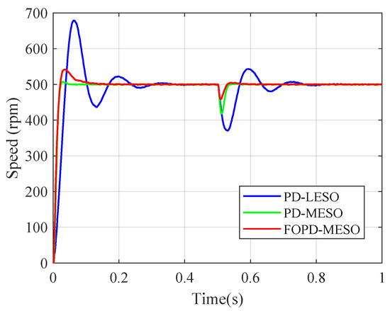
Figure 18.
Step response comparison for the speed loop (experiment).
Table 6.
Indices of the step responses for the speed loop.
5.3. Experimental Tests for the Position Loop
Figure 19 illustrates the step response of the PMSM’s position loop. The legend names represent the different control strategies for comparison, which can be found in Table 2. Consistent with the simulation, the experimental results aligned with the expected outcomes. The setpoint tracking of the LESO-based ADRC exhibited a large overshoot, deviating significantly from the behavior of the nominal control system. In contrast, the setpoint tracking of the MESO-based and the FOC- and MESO-based ADRC aligned with the nominal control system. The disturbance rejection performance of the MESO-based ADRC was significantly improved compared to the LESO-based ADRC. Moreover, the FOC- and MESO-based ADRC further enhanced the disturbance rejection performance based on the MESO-based ADRC, When the disturbance was applied, the position error of the FOC- and MESO-based ADRC improved to 2.2 % from the MESO-based ADRC’s 4.3%.
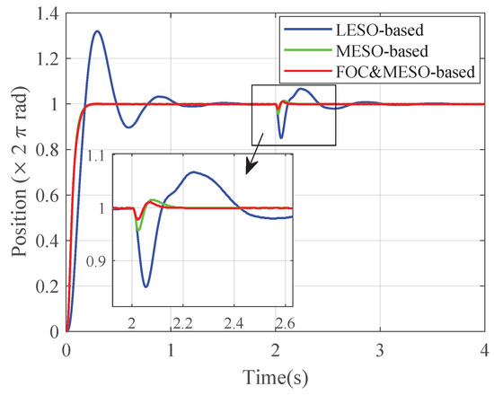
Figure 19.
The step response comparison for the position loop (experiment).
6. Conclusions
This paper has proposed a cascade FOADRC architecture with an MESO for a PMSM position servo system. The MESO-based ADRC was designed for the current, speed, and position loops of the PMSM position servo system. Moreover, a fractional-order PD feedback controller was designed for the speed loop to further improve disturbance rejection performance on the basis of the MESO. The simulation and experimental verification were conducted on a PMSM servo platform. The results demonstrate that the proposed method achieved the desired tracking performance. Additionally, using the same observer bandwidth, the position error of the proposed strategy decreased to 2.25% when the disturbance was input, in contrast to the traditional LADRC’s 14.9% and the MESO-based integer-order ADRC’s 4.3%. The proposed method achieved superior tracking and disturbance rejection performance with a limited observer bandwidth.
Author Contributions
Conceptualization, Y.L., X.L. and Y.C.; methodology, S.W.; software, S.W. and H.G.; validation, S.W. and H.G.; formal analysis, S.W.; investigation, S.W.; writing—original draft preparation, S.W.; writing—review and editing, Y.L., X.L. and Y.C.; visualization, S.W.; supervision, Y.C.; project administration, Y.L. and X.L.; funding acquisition, Y.L. All authors have read and agreed to the published version of the manuscript.
Funding
This research was funded by the National Natural Science Foundation of China (grant number: 51975234).
Data Availability Statement
No new data were created or analyzed in this study.
Conflicts of Interest
The authors declare no conflicts of interest.
Abbreviations
| PMSM | Permanent magnet synchronous motor |
| ADRC | Active disturbance rejection control |
| LADRC | Linear ADRC |
| PID | Proportional-integral-derivative |
| FOC | Fractional-order control |
| FOPD | Fractional-order proportional-derivative |
| FOADRC | Fractional-order ADRC |
| ESO | Extended state observer |
| GESO | Generalized ESO |
| MESO | Model-aided ESO |
References
- Wang, G.; Liu, R.; Zhao, N.; Ding, D.; Xu, D. Enhanced linear ADRC strategy for HF pulse voltage signal injection-based sensorless IPMSM drives. IEEE Trans. Power Electron. 2019, 34, 514–525. [Google Scholar] [CrossRef]
- Chen, W.; Yang, J.; Guo, L.; Li, S. Disturbance-observer-based control and related methods —An overview. IEEE Trans. Ind. Electron. 2016, 63, 1083–1095. [Google Scholar] [CrossRef]
- Liu, H.; Li, S. Speed control for PMSM servo system using predictive functional control and extended state observer. IEEE Trans. Ind. Electron. 2011, 59, 1171–1183. [Google Scholar] [CrossRef]
- Alcántara, S.; Vilanova, R.; Pedret, C. PID control in terms of robustness/performance and servo/regulator trade-offs: A unifying approach to balanced autotuning. J. Process. Control 2013, 23, 527–542. [Google Scholar] [CrossRef]
- Han, J. From PID to Active Disturbance Rejection Control. IEEE Trans. Ind. Electron. 2009, 56, 900–906. [Google Scholar] [CrossRef]
- Gao, Z. Scaling and Bandwidth-Parameterization Based Controller Tuning. In Proceedings of the The 2003 American Control Conference, Denver, CO, USA, 4–6 June 2003; Volume 6, pp. 4989–4996. [Google Scholar]
- Ren, L.; Mao, C.; Song, Z.; Liu, F. Study on Active Disturbance Rejection Control with Actuator Saturation to Reduce the Load of a Driving Chain in Wind Turbines. Renew. Energy 2019, 133, 268–274. [Google Scholar] [CrossRef]
- Fareh, R.; Khadraoui, S.; Abdallah, M.Y.; Baziyad, M.; Bettayeb, M. Active Disturbance Rejection Control for Robotic Systems: A Review. Mechatronics 2021, 80, 102671. [Google Scholar] [CrossRef]
- Sun, H.; Sun, Q.; Wu, W.; Chen, Z.; Tao, J. Altitude Control for Flexible Wing Unmanned Aerial Vehicle Based on Active Disturbance Rejection Control and Feedforward Compensation. Int. J. Robust Nonlinear Control 2020, 30, 222–245. [Google Scholar] [CrossRef]
- Liu, J.; Sun, M.; Chen, Z.; Sun, Q. Output Feedback Control for Aircraft at High Angle of Attack Based upon Fixed-Time Extended State Observer. Aerosp. Sci. Technol. 2019, 95, 105468. [Google Scholar] [CrossRef]
- Meng, Y.; Liu, B.; Wang, L. Speed Control of PMSM Based on an Optimized ADRC Controller. Math. Probl. Eng. 2019, 2019, 1074702. [Google Scholar] [CrossRef]
- Wu, Z.; Zhou, H.; Guo, B.; Deng, F. Review and New Theoretical Perspectives on Active Disturbance Rejection Control for Uncertain Finite-Dimensional and Infinite-Dimensional Systems. Nonlinear Dyn. 2020, 101, 935–959. [Google Scholar] [CrossRef]
- Li, D.; Ding, P.; Gao, Z. Fractional Active Disturbance Rejection Control. ISA Trans. 2016, 62, 109–119. [Google Scholar] [CrossRef] [PubMed]
- Du, Y.; Cao, W.; She, J. Analysis and Design of Active Disturbance Rejection Control With an Improved Extended State Observer for Systems With Measurement Noise. IEEE Trans. Ind. Electron. 2023, 70, 855–865. [Google Scholar] [CrossRef]
- Guo, B.; Bacha, S.; Alamir, M.; Hably, A.; Boudinet, C. Generalized integrator-extended state observer with applications to grid-connected converters in the presence of disturbances. IEEE Trans. Control Syst. Technol. 2020, 29, 744–755. [Google Scholar] [CrossRef]
- Chen, P.; Luo, Y. A two-degree-of-freedom controller design satisfying separation principle with fractional-order PD and generalized ESO. IEEE/ASME Trans. Mechatron. 2021, 27, 137–148. [Google Scholar] [CrossRef]
- Fu, C.; Tan, W. Tuning of linear ADRC with known plant information. ISA Trans. 2016, 65, 384–393. [Google Scholar] [CrossRef] [PubMed]
- Fu, C.; Tan, W. Control of Unstable Processes with Time Delays via ADRC. ISA Trans. 2017, 71, 530–541. [Google Scholar] [CrossRef]
- Zhou, R.; Tan, W. Analysis and Tuning of General Linear Active Disturbance Rejection Controllers. IEEE Trans. Ind. Electron. 2019, 66, 5497–5507. [Google Scholar] [CrossRef]
- Liu, H.; Lin, W.; Liu, Z.; Buccella, C.; Cecati, C. Model Predictive Current Control With Model-Aid Extended State Observer Compensation for PMSM Drive. IEEE Trans. Power Electron. 2023, 38, 3152–3162. [Google Scholar] [CrossRef]
- Cui, S.; Zhu, G.; Zhao, T. Linear Active Disturbance Rejection Control-Based Diagonal Recurrent Neural Network for Radar Position Servo Systems with Dead Zone and Friction. Appl. Sci. 2022, 12, 12839. [Google Scholar] [CrossRef]
- Wang, Y.; Fang, S.; Hu, J. Active Disturbance Rejection Control Based on Deep Reinforcement Learning of PMSM for More Electric Aircraft. IEEE Trans. Power Electron. 2023, 38, 406–416. [Google Scholar] [CrossRef]
- Zhang, Z.; Cheng, J.; Guo, Y. PD-Based Optimal ADRC with Improved Linear Extended State Observer. Entropy 2021, 23, 888. [Google Scholar] [CrossRef] [PubMed]
- Dastjerdi, A.A.; Vinagre, B.M.; Chen, Y.; HosseinNia, S.H. Linear fractional order controllers; A survey in the frequency domain. Annu. Rev. Control 2019, 47, 51–70. [Google Scholar] [CrossRef]
- Shi, X.; Chen, Y.; Huang, J. Application of Fractional-Order Active Disturbance Rejection Controller on Linear Motion System. Control Eng. Pract. 2018, 81, 207–214. [Google Scholar] [CrossRef]
- Wang, S.; Gan, H.; Luo, Y.; Wang, X.; Gao, Z. Active Disturbance Rejection Control with Fractional-Order Model-Aided Extended State Observer. ISA Trans. 2023, 142, 527–537. [Google Scholar] [CrossRef]
- Zhao, M.; Hu, Y.; Song, J. Improved Fractional-Order Extended State Observer-Based Hypersonic Vehicle Active Disturbance Rejection Control. Mathematics 2022, 10, 4414. [Google Scholar] [CrossRef]
- Zhao, J.; Zhao, T.; Liu, N. Fractional-Order Active Disturbance Rejection Control with Fuzzy Self-Tuning for Precision Stabilized Platform. Entropy 2022, 24, 1681. [Google Scholar] [CrossRef]
- Chen, P.; Luo, Y.; Peng, Y.; Chen, Y. Optimal Fractional-Order Active Disturbance Rejection Controller Design for PMSM Speed Servo System. Entropy 2021, 23, 262. [Google Scholar] [CrossRef]
- Tian, G.; Gao, Z. Frequency Response Analysis of Active Disturbance Rejection Based Control System. In Proceedings of the 2007 IEEE International Conference on Control Applications, Singapore, 1–3 October 2007; pp. 1595–1599. [Google Scholar]
Disclaimer/Publisher’s Note: The statements, opinions and data contained in all publications are solely those of the individual author(s) and contributor(s) and not of MDPI and/or the editor(s). MDPI and/or the editor(s) disclaim responsibility for any injury to people or property resulting from any ideas, methods, instructions or products referred to in the content. |
© 2024 by the authors. Licensee MDPI, Basel, Switzerland. This article is an open access article distributed under the terms and conditions of the Creative Commons Attribution (CC BY) license (https://creativecommons.org/licenses/by/4.0/).