Abstract
Although field medical microgrids have been widely studied as an important component of future medical power systems, current sharing control in field medical microgrids under false information injection (FDI) attacks has rarely been researched. Based on this, this paper proposes a distributed fuzzy control method for power sharing in field medical microgrids considering communication networks under FDI attacks. First, the field medical microgrid is modeled as a multi-bus DC microgrid system with power coupling. To provide voltage control and initial current equalization, fractional order PI control is applied. In order to reduce the model complexity, the concept of block modeling is employed to transform the model into a linear heterogeneous multi-agent system. Secondly, a fully distributed current sharing fuzzy control strategy is proposed. It can precisely realize current sharing control and reduce the communication bandwidth. Finally, the proposed control strategy is verified by simulation results.
1. Introduction
The field medical system is one of the most important types of health equipment for national health protection and health emergency rescue [1]. The reliable and stable operation of the electric power system plays a key role in the smooth implementation of the field medical treatment mission and the effectiveness of guard duty protection. However, current sharing control in field medical microgrids under FDI attacks has rarely been researched. The field medical microgrid has been widely noted and studied for its high reliability, flexibility, scalability and energy diversity [2]. Both DC microgrids and AC microgrids can be used for field medical power systems. Since field renewable energy sources (such as solar photovoltaic panels and wind turbines) are a kind of DC source, the use of DC microgrids reduces the DC/AC conversion frequency and reduces energy conversion losses. It improves the energy storage efficiency, reduces power factor problems [3], and avoids skin effect [4]. Meanwhile network attacks can cause interference to the power sharing of field medical microgrids. Therefore, this paper proposes a distributed consensus fuzzy control method for power sharing of the field medical DC microgrid under FDI attacks.
With the development and application of the theory of fractional order calculus, fractional order controllers have received widespread attention [5]. Numerous studies have shown that fractional order PI controllers are superior to integer order PI controllers [6,7]. This has solved numerous problems in the medical, electrical, and mathematical fields.
This paper proposes a distributed dynamic fuzzy control strategy for multi-bus DC microgrids with power coupling, which is dedicated to the study of the
consistency of MASs under FDI attacks. The main contributions of this paper are as follows:
- A system model of a multi-bus DC microgrid displaying a power coupling relationship between distributed power sources and loads in a region is developed. The microgrid system model is further switched into a linear heterogeneous MAS with unknown attacks. A distributed consensus secondary control method based on local communication network structure information is proposed to achieve accurate power distribution in the microgrid.
- In order to mitigate the impact of FDI attacks on the consistency of MASs, a security control protocol is proposed. The security controller is designed to reduce the impact of FDI attacks on sensors and actuators on the control commands of agents, and ensure the consistency of the MASs’ output.
- In order to reduce the communication burden, a fully distributed fuzzy control method is proposed, which emphasizes the discontinuous communication mode between distributed generators. This method effectively reduces the update frequency of the controller and the communication bandwidth under the condition of ensuring the control effect.
2. Research Background
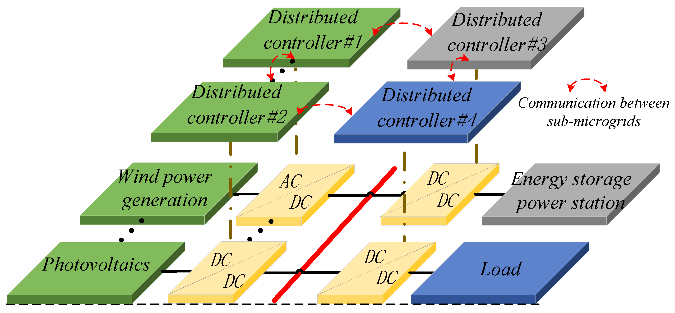
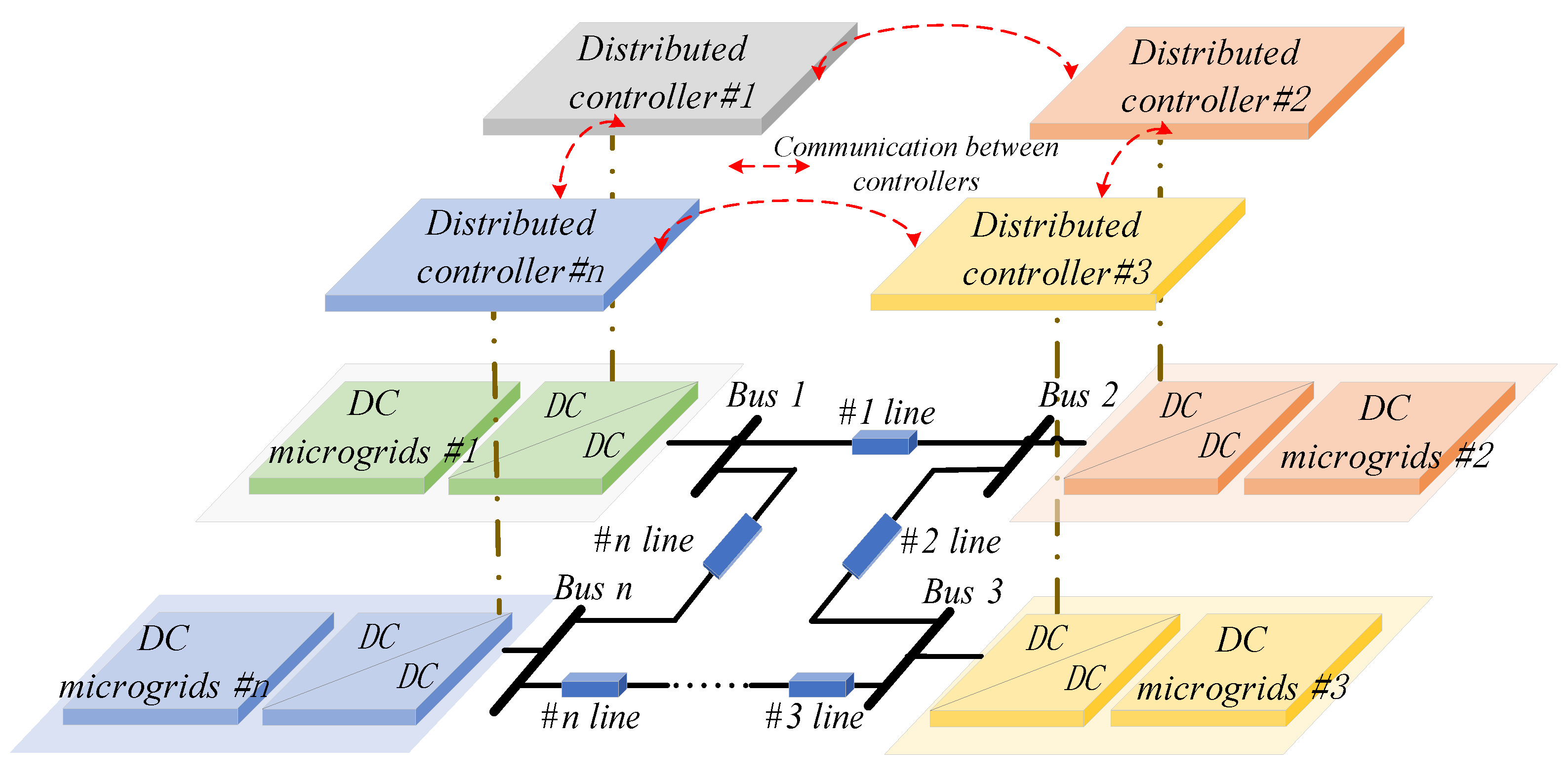
In reviewing previous research results, the application of distributed control primarily focuses on single-bus microgrid systems [8,9,10,11], which are shown in Figure 1. When a fault occurs in the bus, the entire system fails to operate properly. As the capacity and size of microgrids continue to grow, DC microgrids have started to use the multi-bus structure [12,13]. The multi-bus structure improves the reliability of the power supply and meets the demand for flexible access to various types of distributed power supply. The multi-bus structure is shown in Figure 2. The existence of multiple DC buses in the system not only greatly improves the efficiency and reliability of the power supply, but also makes it possible for various types of power sources to access the grid more conveniently and efficiently. This structure further enhanced the reliability and stability of the entire field medical microgrid. Therefore, this paper focused on multi-bus DC microgrids.

Figure 1.
Schematic diagram of the single-bus DC microgrid.

Figure 2.
Schematic diagram of the multi-bus DC microgrid.
Although droop control could achieve voltage regulation, accurate current sharing is not achieved due to the imbalanced impedance in DC microgrids [14,15,16]. Therefore, it is no longer applicable for distributed power sharing with different impedance characteristics. To achieve a precise power distribution among different distributed energy sources and improve the communication efficiency of parallel converters, a voltage-based voltage drop method was proposed in the literature [17]. It controlled a DC power supply by superimposing a small AC voltage on the output DC voltage of the converter. In the literature [18], a new control algorithm was proposed to enable accurate power sharing in DC microgrids. The proposed strategy did not required prior information about the grid topology and parameters. However, both of these methods required new communication circuits to be added to the original circuit topology model. To further achieve voltage control and proportional power sharing, a communication-based secondary control strategy for microgrids was proposed in literature [19]. This strategy could automatically adjust under different operating modes without relying on underlying communication. However, this method had the drawback of requiring many communication and computation tasks, making it prone to single points of failure. Traditional centralized secondary control methods had high demands on communication networks and computational processing capabilities. Thus, the communication links were relatively complex and prone to faults. Note that power sharing is essentially current sharing for DC microgrids.
To address the limitations of droop control, secondary control was widely applied in microgrids. The centralized control method relied on a central controller and required extensive data transmission. This significantly increased the computational complexity and burden. Therefore, this paper employed a distributed control method based on a multi-agent system (MAS). In the distributed control structure of the microgrid, each distributed generation (DG) unit was considered as an agent, and the microgrid was viewed as a MAS. In the distributed control method, each DG only needed to exchange information with its neighboring DGs to achieve control objectives. This method simplified the communication network, effectively avoided single-point failures, and ensured high reliability. In the literature [20], a two-module secondary controller method based on a coherent algorithm was proposed, which was able to regulate the global voltage and achieve proportional current distribution. In the literature [21], in order to achieve DC microgrid voltage stabilization control, a control scheme with a discrete consistency algorithm in a stand-alone photovoltaic-storage DC microgrid model was proposed. In the literature [22], a hybrid distributed secondary controller was proposed, which consists of a continuous part and a discrete part. This strategy reduced the use of communication resources and achieved current sharing and DC voltage regulation. In the literature [23], a consistency control strategy based on the leader–follower method was proposed, which required information exchange only between the leader node of the distributed units and the bus. It reduced the communication links between other follower nodes and the bus. This method alleviated the communication pressure to some extent and effectively guaranteed the performance of the microgrid control system. However, the above studies focused on distributed control strategies under free communication conditions and overlooked network attacks on communication links among MASs. Modern microgrids rely on communication networks and information technology, making them more susceptible to network attacks. Therefore, this paper proposed an accurate power-sharing control strategy under network attacks.
As network communication technology has advanced, network security has become a fundamental requirement for the informatization construction in our country. Attackers conduct network attacks through software application vulnerabilities, insecure network protocols, etc. Attackers hack into target hosts and gain advanced privileges or plant viruses for profit, which causes incalculable damage to power grid operations. In multi-agent systems (MASs), the information is exchanged between agents by networks. However, due to the openness of networks, communication networks are highly susceptible to network attacks. Thus, the system consistency is affected. Generally, network attacks are categorized into two types based on the methods used: denial-of-service (DoS) attacks and deception attacks. DoS attacks typically aim to disrupt the transmission of signals in communication channels between or within agents. Unlike DoS attacks, deception attacks eavesdrop on and tamper with real data in the network. Ultimately, the receiving intelligence is made to process the tampered error data as real signals. Comparatively, deception attacks cause more severe damage to the entire MAS. As a type of deception attack, false data injection (FDI) attack disrupted system consistency by injecting interfering data into real data. Due to the disguising nature of this attack method, it is difficult for the system to detect it. In the literature [24], an adaptive Markov process-based defense strategy was proposed to avoid smart grid systems from being attacked by unfamiliar attackers. In the literature [25], to counter known network attack models, the authors proposed a novel network attack resistance mechanism based on the design concept of interval state estimation. However, the above study primarily focused on the detection and defense issues of false data injection attacks in network physical power systems. When the microgrid system was subjected to disturbances such as small load perturbations and power fluctuations of distributed power sources at the same time, the problem of the safe operation of the system became more complicated. But very little research has been performed on such issues. Most current studies on output synchronization under FDI attacks concentrate on homogeneous qualities [26,27,28,29,30,31,32,33,34]. The challenge in the study of heterogeneous systems is the inability to directly design adaptive attack compensators. The use of adaptive compensators in uniform mass alone is not sufficient to synchronize the system with the output. In distributed power systems, the processing capacity and load of each node might also differ. In power systems, different generation equipment and loads have different dynamic characteristics and quality parameters. Therefore, studying the synchronization of heterogeneous qualities under FDI attacks is particularly important.
3. Modeling of Multi-Bus DC Microgrid System
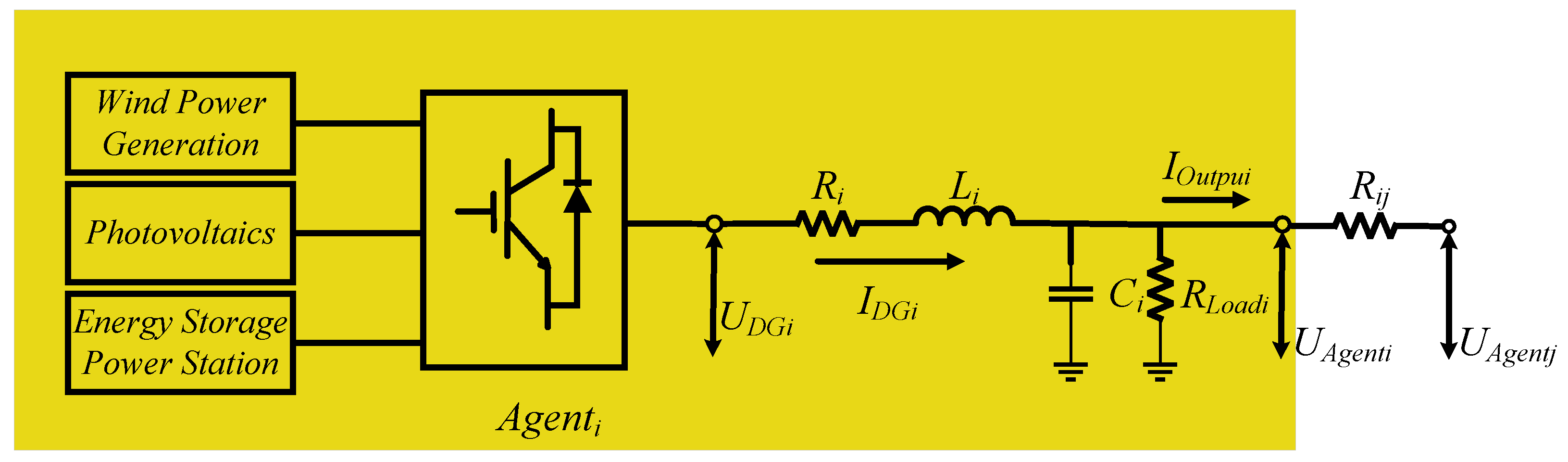
The multi-bus DC microgrid in Figure 2 can be switched into multiple agents including distributed generation, loads and buses. The ith agent model is analyzed separately, and its Thevenin equivalent circuit diagram is shown in Figure 3. Here,
and
are the output voltage and current of distributed generation, respectively.
is the output current of the ith agent.
and
are the point voltages of the ith and jth agent, respectively.
is the line resistance between the ith agent and the jth agent.
,
and
are the RLC filter parameter values of the ith agent, respectively. In the DC microgrid, the power loss within the agents depends on
, and the power loss between the agents depends on
.
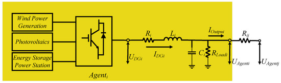
Figure 3.
Equivalent Thevenin model of single agent.
According to the Thevenin equivalent circuit in Figure 3, the mathematical model of the ith agent can be obtained as
Let
,
. The model of Equations (1) and (2) becomes
where
are the state variable, output variable and input variable of the ith agent, respectively, and
is the sag coefficient of the system,
,
,
,
. In addition, the power coupling between the
agent and the
agent will be generated through
.
is expressed as
in the system state space function.
To provide stable voltage and current outputs, zero level controllers are used [35]. The zero level controllers used in this paper are Plug and Play (PnP) controllers, which are designed to be adjusted using the positive, negative and amplitude of the error signal. Its mathematical model is shown below:
where
where
are PnP controller parameters of
respectively, and
is the rated voltage of
.
To provide voltage regulation and current sharing, a fractional order PI controller is used. Its mathematical model is shown below:
where
represents the slave controller,
are the gain link coefficients and integral link coefficients of the fractional order PI controller, respectively,
is the adjustable parameter of the fractional order PI controller,
is the ideal voltage at no load for the ith agent, and
is the droop coefficient, which the smaller it is, the more stable to system [36].
A multilevel bandwidth division control strategy was studied in this paper. It divided the control bandwidth into three different levels, each of which is responsible for the control tasks of different frequency bands. This control strategy ensured the overall stability of the system and enabled coordinated operation at all levels. If the control bandwidth of one controller is more than 5 times higher than that of the other controller, the interaction between the two controllers will be ignored.
Let
,
,
,
,
, and Equation (5) becomes
updated to
becomes
According to Equations (3), (4) and (6)–(8), the state space function model of a linear heterogeneous MAS for multi-bus DC microgrids is as follows:
where
,
,
,
,
,
.
Due to the difference between the actual system and the ideal conditions, the following functions are satisfied in the actual power system:
Based on this, the power coupling term
can be redefined as follows: for
,
, where
. Because the limitation of the actual device is bounded, this means that
is bounded. The ith linear heterogeneous multi-agent model can be expressed as
where
.
,
,
. Since there is no ideal leader in the actual power system, we believe that the leader is virtual, and the dynamics of the leader can be expressed as
A directed graph
is used to represent the information transfer relationship between a leader and N agents, where
represents the leader and
is used to describe the information transfer between agents. Specifically,
represents the weight adjacency matrix, and
represents the set of agents.
represents the set of directed edges formed by connecting two agents. N is the number of followers. If the ith agent can obtain information from the jth agent, there are
and the jth agent is said to be the inner neighbor or neighbor agent of the ith agent, otherwise,
. Let
denote the index set of neighbors in the ith agent. The Laplace matrix of the agent system is defined as
. When i = j,
, otherwise,
. Let
denote the adjacency matrix between the leader and the intelligence. Specifically, if the agent can obtain the information of the leader, there is an edge from the leader to the ith agent and
, otherwise,
.
is called a directed path from agent i to agent m, and
represents different agents.
To achieve accurate power sharing that guarantees
consistency for linearly heterogeneous multi-intelligentsia, it is necessary to satisfy
,
and
. The following three assumptions are met:
Assumption 1. There is a directed spanning tree with the leader as the root node in the topology of the systems (18) and (19), which means that there is at least one directed path from the leader to each follower.
Assumption 2. The existence matrices
and
satisfy the following conditions:
Assumption 3. For
and
,
is column full rank and
is row full rank.
In this section, a multi-bus DC microgrid system with power coupling is modeled and equated to a linear heterogeneous multi-agent system. This is an essential part of the controller design.
4. Fuzzy Control Strategy for Current Sharing with FDI Attacks
4.1. Types of FDI Attack and Design of Adaptive Compensator
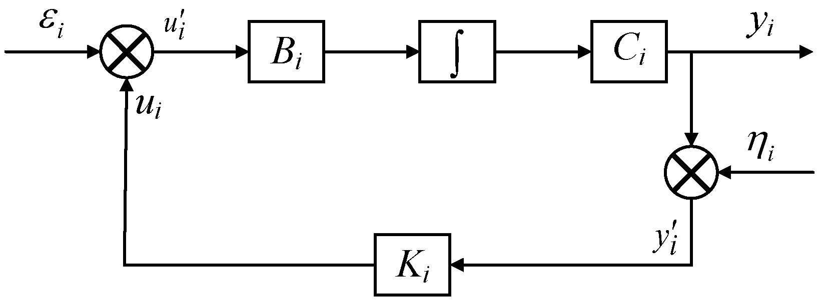
Unlike the consideration of random attacks in references [30,31,32], this section studies continuous FDI attacks. In actual attack environments, it is almost impossible to obtain real-time status information of the system. Only the measured output signals can be used. Therefore, this paper uses the output signal of the system and injects the attack signal into the sensors and actuators of the ith agent. Combining Equations (21) and (22), the structure of the FDI attack is shown in Figure 4. To alleviate the impact of continuous FDI attacks on output synchronization performance, this paper designs an output -based adaptive compensator and proposes an elastic static output feedback collaborative controller.

Figure 4.
Attack model under static output feedback control strategy.
In the figure,
is the controller gain matrix with corresponding dimensions,
is the output gain matrix with the corresponding dimension,
is the gain matrix of the compensator.
The mathematical model of the attacker’s attacks on the actuator can be expressed as
where
is the elastic control protocol to be designed,
is the attack signal injected into the actuator,
is the false control input used by the actuator.
Under attacks, the output signal obtained by the ith agent can be described as
where
is the actual output of the agent,
is the attack signal,
is the false output information used by the controller.
Remark 1.
The external attacks are bounded. For attackers, it is unrealistic to inject a signal approaching infinity, which will be physically or logically limited (such as traffic limit, resource limit, etc.). These signals are differentiable because their changes are continuous. For example, the total amount of traffic sent by bandwidth limiting attacks is limited by the physical limit of the network bandwidth. The growth of traffic is continuous; the amount of data sent per second gradually increases instead of reaching the maximum instantly. The power consumption of the device is limited by the physical power consumption and will not increase indefinitely. The following conditions are met:
where
Remark 2.
Paranoid attacks and sinusoidal attacks are not rare in our daily life. They cause great harm. Paranoid attacks of smart grids can lead to power load forecasting errors through subtle data tampering, and then lead to power supply imbalance. Sinusoidal attacks may disturb the stability of industrial control systems and affect the production process through periodic data fluctuations. Therefore, the types of FDI attacks considered in this paper are paranoid attacks and sinusoidal attacks.
According to the literature [37], the adaptive compensator elastic control protocol introduced in this paper can be expressed as
where
is a standard of controller using the injection of the FDI attack output,
is a compensator to be designed, and
can be expressed as
where
is the compensator gain matrix,
is the state of the auxiliary system to be designed,
is the matrix satisfying the corresponding dimension of Equation (20), and
is updated as
is updated as
where
is the given symmetric positive definite matrix,
is the scalar design parameter for adjusting the synchronization error, † is the pseudo inverse, and
is the matrix satisfying the following formula:
Based on the above, the state equation of linear heterogeneous MASs under an FDI attack is
4.2. Design of Fuzzy Logic Controller
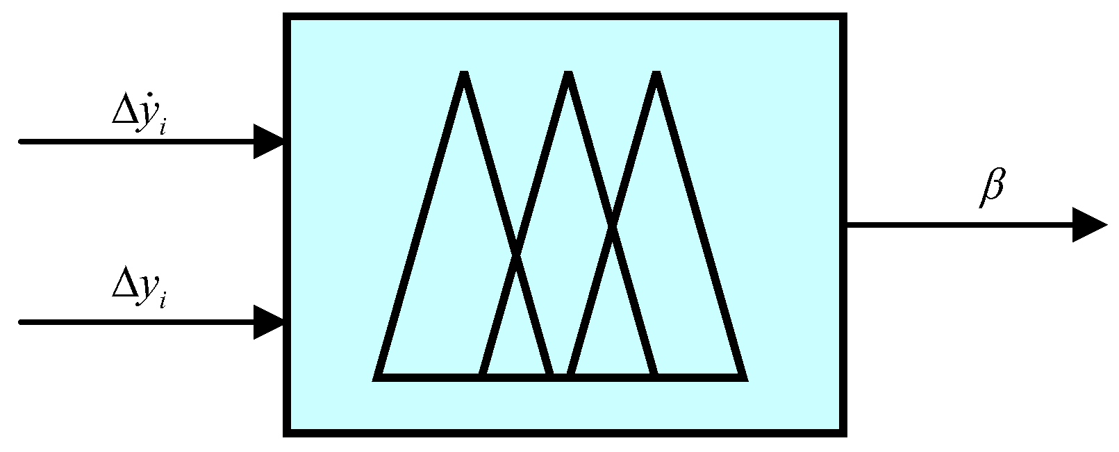
In this section, the design of a fuzzy logic controller (FLC) under an FDI attack is proposed. The input of an FLC is the variation
of the output
of the MASs and the derivative
of the variation. The subset of
can be abbreviated as
. The
subset can be abbreviated as
. The fuzzy subset of the output value
of the FLC is
. The FLC structure is shown in Figure 5. The fuzzy control rules are shown in Table 1. The output update threshold is shown in Table 2.
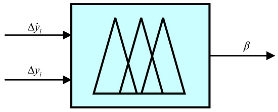
Figure 5.
Schematic diagram of fuzzy logic controller structure.

Table 1.
Fuzzy control rules.
Table 2.
Output update threshold.
The membership function is stored in the membership function library, which is used to convert digital clarity into fuzzy quantity. The distribution of fuzzy subsets in the universe of variables is uneven. In this paper, the triangular membership function with a large slope is used, which not only improves the speed control accuracy near the balance zero, but also makes the system quickly move from far away from the balance point to near the balance point when the deviation is large. The membership function is shown in Figure 6.
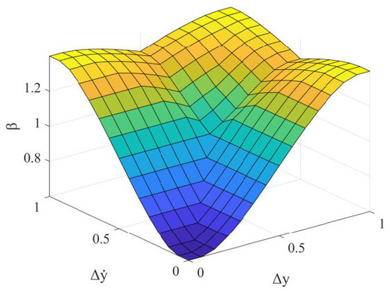
Figure 6.
Membership function diagram.
4.3. Criteria for Consistency of Continuous Linear Heterogeneous Multi-Agent Systems
This section first introduces some theorems that need to be used.
Theorem 1.
The conditions for continuous systems to achieve output consistency are
Theorem 2.
The necessary and sufficient condition for the systems (18) and (19) to achieve
consistency is that there is a symmetric positive definite matrix
,
and scalar
satisfying the following inequality:
where
.
Theorem 3.
Assuming that the system (29) satisfies the assumptions (1)–(3), the necessary and sufficient condition for it to achieve
consistency under the action of the controller (24) and the dynamic compensator (25) is that there are symmetric positive definite matrices
and
,
, which meet the following requirements [38]:
where
where
are the orthogonal complement matrices of
, respectively.
Unlike the controller based on state feedback, due to the existence of Equation (36), the unknown gain matrix
and
of the controller based on output feedback cannot be directly obtained through the LMI toolbox of MATLAB. Therefore, this paper uses a new iterative algorithm for calculating the gain of static of the controller [39]. The specific steps are as follows:
Step 1: Find out the feasible solution of a set of matrices
that meet the following conditions.
where
Step 2: Let
,
. Find out the feasible solution of a set of matrices
that meet the following conditions:
where
.
Step 3: Let
,
.
Then, output
. Else return to step 2. Here,
is the given maximum error value,
.
Step 4: By taking the output
into Equation (33), the gain of the unknown matrix of the system can be solved by the LMI toolbox.
5. Simulation Results
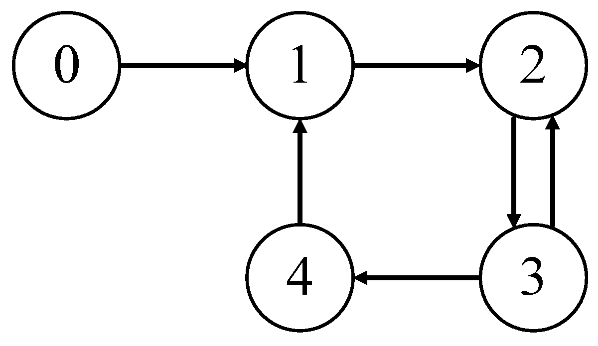
In order to verify that the method proposed in this paper can ensure the stability of the microgrid system when it undergoes FDI attacks, a simulation experiment is carried out in the Matlab environment. Considering the universality and the inherent complexity of the system, a linear heterogeneous MAS containing one leader and four followers was used. Its structure is shown in Figure 7.

Figure 7.
Communication topology between leader and followers.
The line resistance between the agents is
=
= 0.5
;
=
= 0.2
;
=
= 0.8
;
=
= 1
;
=
= 0.4
. The whole load of each agent is
= 1
;
= 1.5
;
= 3
;
= 1.5
;
= 3
. The RLC filter parameter values of the multi-bus DC microgrid are shown in Table 3, and the PnP parameters are shown in Table 4. The fractional order PI controller has gain link coefficients
, integral link coefficients
and
[36]. The required gain
= 1.8259, 1.7286, 1.7340, 1.7345 and
can be obtained through Equations (43)–(47).
Table 3.
RLC filter parameter values.
Table 4.
PnP parameter values.
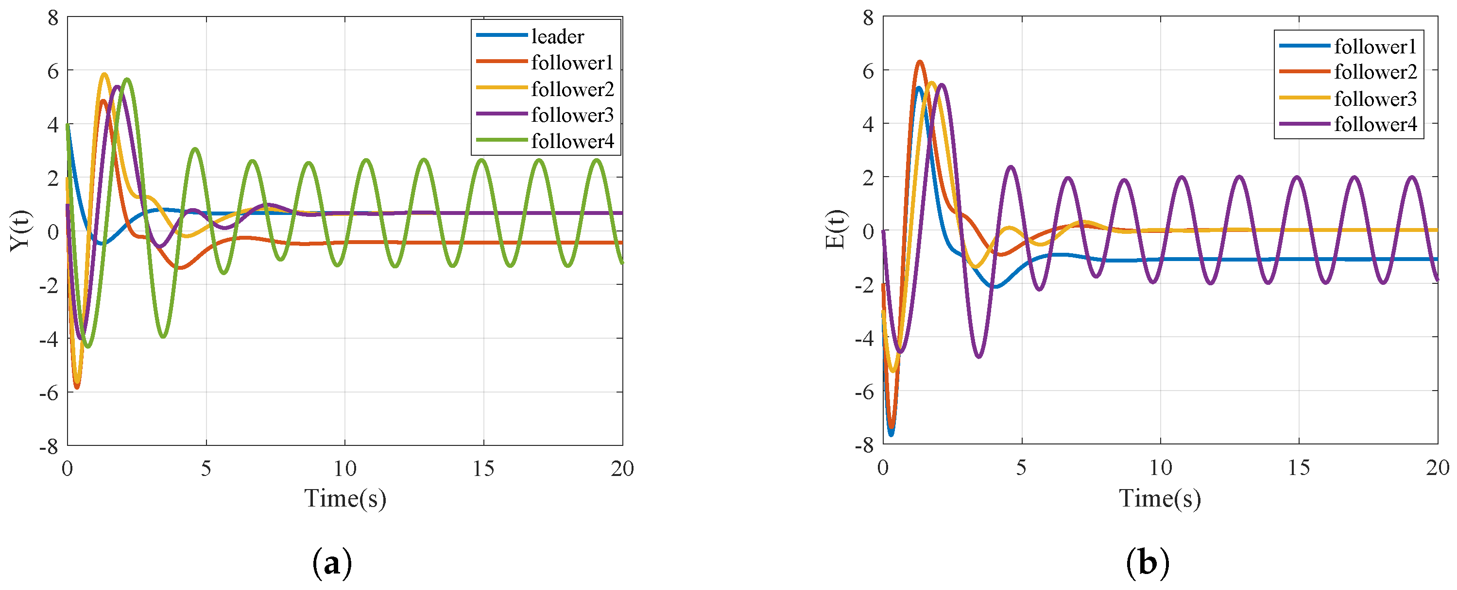
The FDI paranoid attack signal injected into the sensor and actuator is
, and the sine attack signal is
. The FDI attack degree is within an acceptable degree. Figure 8 and Figure 9 show the output and output errors of MASs under no attack and FDI injection attacks, respectively. The unattached MASs can quickly achieve output consistency, while the MASs injected with paranoia and sine attacks cannot achieve
consistency. The system will continue to oscillate and maintain a relatively large synchronization error boundary.
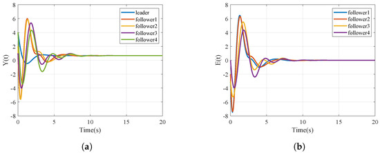
Figure 8.
Output and output error of multi-agent without attacks. (a) Output of MASs without attacks; (b) output error of MASs without attacks.
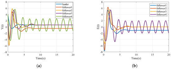
Figure 9.
Output and output error of multi-agent under FDI attacks. (a) output of MASs with attacks; (b) Output error of MASs with attacks.
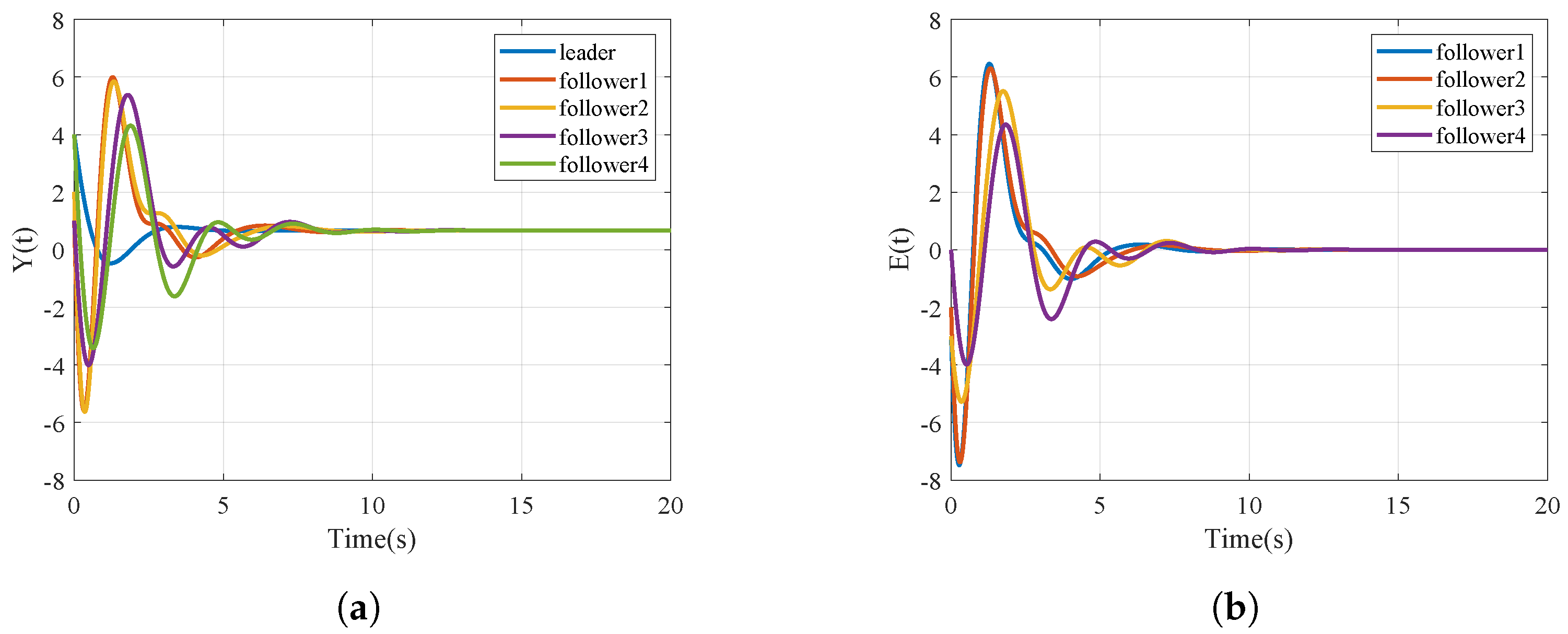
Figure 10 shows the output and error of the MASs using compensators. It is evident from the figure that the control with the compensator can greatly mitigate the impact of FDI attacks on DC microgrids. The compensated controller achieves a better synchronization performance.
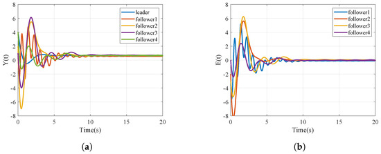
Figure 10.
Output and output error of multi-agent systems with compensators under FDI attacks. (a) Output of MASs with compensator; (b) output error of MASs with compensator.
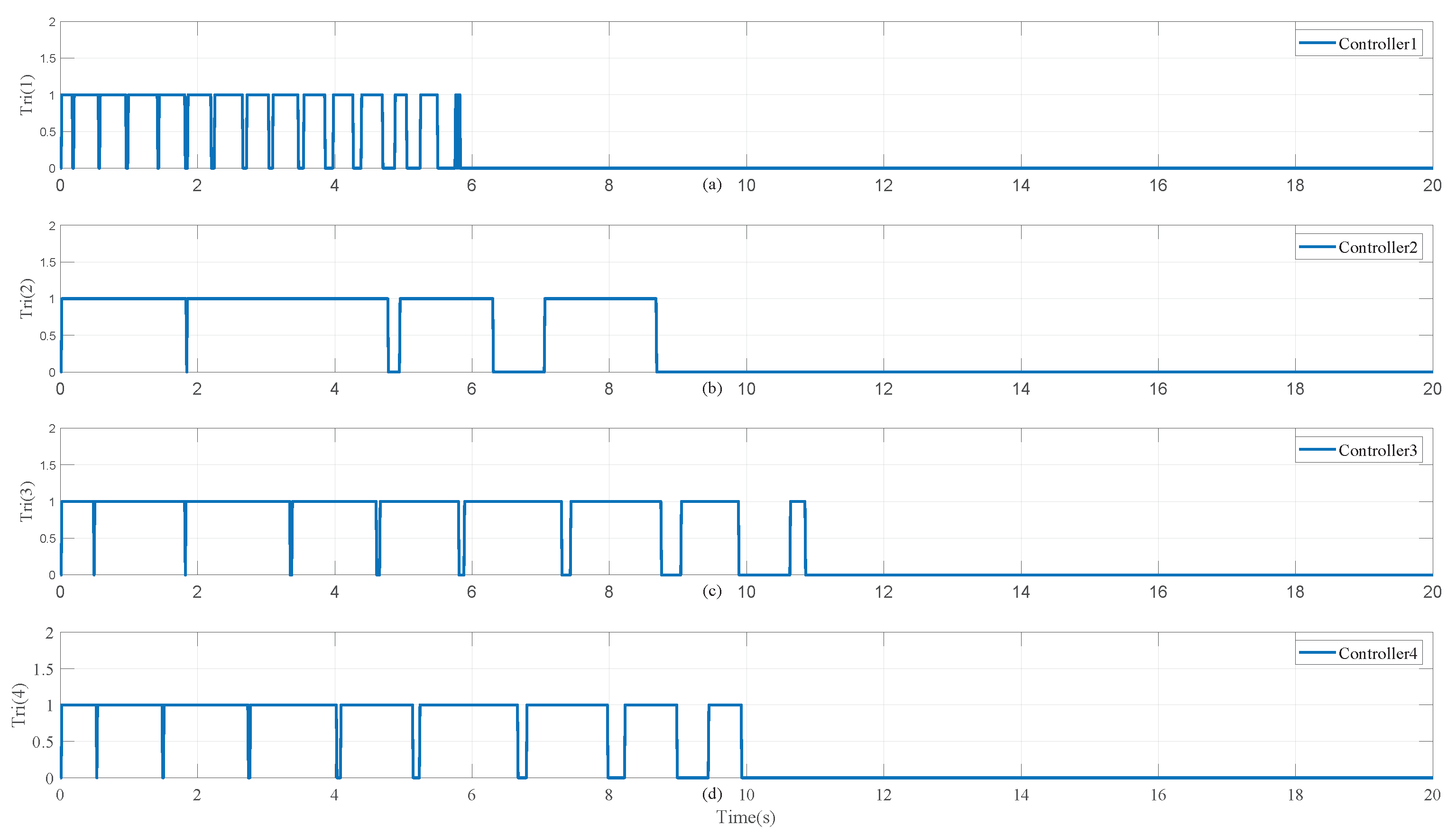
When the FLC is triggered,
, otherwise,
. The simulation results are shown in Figure 11 and Figure 12. From the simulation results, it is evident that the fuzzy logic controller system processes this information more efficiently and reduces the communication bandwidth. Compared with the literature [37], the method in this paper can effectively reduce the number of communications and ensures the output consistency without affecting the system’s performance and response speed.

Figure 11.
Fuzzy control multi-agent output and output error with compensator under FDI attacks. (a) output of MASs with FLC; (b) Output error of MASs with FLC.
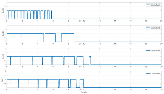
Figure 12.
FLC trigger update time: (a) follower 1 update time; (b) follower 2 update time; (c) follower 3 update time; (d) follower 4 update time.
6. Conclusions
In the context of field medical microgrids with an increasing proportion of distributed power sources, it is difficult for single-bus systems to adapt to complex power demand changes and distributed energy access needs. A distributed consensus fuzzy control method and fractional order control for power sharing have been proposed to solve the problems of unbalanced power sharing for field medical microgrids in this paper. This method has improved the reliability and adaptability of field medical microgrids, enabling them to better cope with various uncertainties and dynamic changes in the actual field. Under this distributed control framework, the proposed method has enabled coordination among nodes through limited communication without the need for global information from a centralized controller, which has effectively reduced the communication burden and improved the robustness and scalability of the system. Finally, the effectiveness of the proposed method has been verified by a simulation.
Future research will consider nonlinear heterogeneous multi-agent systems, with the aim of improving the security and robustness of the control system against more types of network attacks. Emerging technologies such as artificial intelligence, big data analytics and Internet of Things will be combined to improve the intelligence of current shared control strategies.
Author Contributions
Conceptualization, W.Z. and L.L.; methodology, C.W., W.Z. and L.L.; software, C.W.; validation, C.W.; formal analysis, C.W.; investigation, W.Z. and L.L.; resources, W.Z.; data curation, C.W.; writing—original draft preparation, C.W.; writing—review and editing, W.Z. and L.L.; visualization, W.Z. and L.L.; supervision, L.L. and R.W.; project administration, R.W.; funding acquisition, R.W. All authors have read and agreed to the published version of the manuscript.
Funding
This research received no external funding.
Data Availability Statement
Data are contained within the article.
Conflicts of Interest
The authors declare no conflicts of interest.
References
- Zhirong, X.; Xingyun, R.; Rongjun, W. Introduction to medical care system for field battle. Southwest Def. Med. 2005, 15, 540–542. [Google Scholar] [CrossRef]
- Ningning, Y.; Yuchao, H.; Lulin, T.; Rong, J.; Chaojun, W. Research on variable order fractional PIλ controller based on fuzzy rules. J. Xi’an Univ. Technol. 2017, 33, 304–309. [Google Scholar] [CrossRef]
- Wang, R.; Yu, X.; Sun, Q.; Li, D.; Gui, Y.; Wang, P. The Integrated Reference Region Analysis for Parallel DFIGs’ Interfacing Inductors. IEEE Trans. Power Electron. 2024, 39, 7632–7642. [Google Scholar] [CrossRef]
- Liu, G.; Liu, J.; Xiao, X.; Sun, C.; Wang, R.; Sun, Q. Voltage Current Cooperative Control for DC Microgrid Under Input Unknown. In Proceedings of the IECON 2023—49th Annual Conference of the IEEE Industrial Electronics Society, Singapore, 16–19 October 2023; pp. 1–5. [Google Scholar] [CrossRef]
- Dingyu, X.; Chunna, Z. Fractional order PID controller design for fractional order system. Control. Theory Appl. 2007, 24, 771–776. [Google Scholar] [CrossRef]
- Xiao, M.; Tao, B.; Zheng, W.X.; Jiang, G. Fractional-Order PID Controller Synthesis for Bifurcation of Fractional-Order Small-World Networks. IEEE Trans. Syst. Man Cybern. Syst. 2021, 51, 4334–4346. [Google Scholar] [CrossRef]
- Stanisławski, R.; Rydel, M.; Li, Z. A New Reduced-Order Implementation of Discrete-Time Fractional-Order PID Controller. IEEE Access 2022, 10, 17417–17429. [Google Scholar] [CrossRef]
- Zhang, N.; Yang, D.; Zhang, H.; Luo, Y. Distributed control strategy of DC microgrid based on consistency theory. Energy Rep. 2022, 8, 739–750. [Google Scholar] [CrossRef]
- Che, L.; Shahidehpour, M.; Alabdulwahab, A.; Al-Turki, Y. Hierarchical Coordination of a Community Microgrid with AC and DC Microgrids. IEEE Trans. Smart Grid 2015, 6, 3042–3051. [Google Scholar] [CrossRef]
- Peng, H.; Luan, L.; Xu, Z.; Mo, W.; Wang, Y. Event-Triggered Mechanism Based Control Method of SMES to Improve Microgrids Stability Under Extreme Conditions. IEEE Trans. Appl. Supercond. 2021, 31, 5403604. [Google Scholar] [CrossRef]
- Liu, S.; Siano, P.; Wang, X. Intrusion-Detector-Dependent Frequency Regulation for Microgrids Under Denial-of-Service Attacks. IEEE Syst. J. 2020, 14, 2593–2596. [Google Scholar] [CrossRef]
- Tan, S.; Xie, P.; Guerrero, J.M.; Vasquez, J.C.; Alcala, J.M.; Carreño, J.E.M.; Guerrero-Zapata, M. Lyapunov-Based Resilient Cooperative Control for DC Microgrid Clusters Against False Data Injection Cyber-Attacks. IEEE Trans. Smart Grid 2024, 15, 3208–3222. [Google Scholar] [CrossRef]
- Zhai, M.; Sun, Q.; Wang, R.; Wang, B.; Liu, S.; Zhang, H. Fully Distributed Fault-Tolerant Event-Triggered Control of Microgrids Under Directed Graphs. IEEE Trans. Netw. Sci. Eng. 2022, 9, 3570–3579. [Google Scholar] [CrossRef]
- Tahim, A.P.N.; Pagano, D.J.; Lenz, E.; Stramosk, V. Modeling and Stability Analysis of Islanded DC Microgrids Under Droop Control. IEEE Trans. Power Electron. 2015, 30, 4597–4607. [Google Scholar] [CrossRef]
- Wang, R.; Sun, Q.; Hu, W.; Li, Y.; Ma, D.; Wang, P. SoC-Based Droop Coefficients Stability Region Analysis of the Battery for Stand-Alone Supply Systems With Constant Power Loads. IEEE Trans. Power Electron. 2021, 36, 7866–7879. [Google Scholar] [CrossRef]
- Rui, W.; Qiuye, S.; Dazhong, M.; Xuguang, H. Line Impedance Cooperative Stability Region Identification Method for Grid-Tied Inverters Under Weak Grids. IEEE Trans. Smart Grid 2020, 11, 2856–2866. [Google Scholar] [CrossRef]
- Peyghami, S.; Davari, P.; Mokhtari, H.; Loh, P.C.; Blaabjerg, F. Synchronverter-Enabled DC Power Sharing Approach for LVDC Microgrids. IEEE Trans. Power Electron. 2017, 32, 8089–8099. [Google Scholar] [CrossRef]
- Kirakosyan, A.; El-Saadany, E.F.; Moursi, M.S.E.; Yazdavar, A.H.; Al-Durra, A. Communication-Free Current Sharing Control Strategy for DC Microgrids and Its Application for AC/DC Hybrid Microgrids. IEEE Trans. Power Syst. 2020, 35, 140–151. [Google Scholar] [CrossRef]
- Yang, Q.; Jiang, L.; Zhao, H.; Zeng, H. Autonomous Voltage Regulation and Current Sharing in Islanded Multi-Inverter DC Microgrid. IEEE Trans. Smart Grid 2018, 9, 6429–6437. [Google Scholar] [CrossRef]
- Nasirian, V.; Moayedi, S.; Davoudi, A.; Lewis, F.L. Distributed Cooperative Control of DC Microgrids. IEEE Trans. Power Electron. 2015, 30, 2288–2303. [Google Scholar] [CrossRef]
- Jinfeng, C.; Ke, J.; Zhenwen, X.; Rui, Z. Voltage Control Strategy of DC Microgrid Based on Discrete Consensus Algorithm. Zhejiang Electric Power 2019, 38, 65–71. [Google Scholar] [CrossRef]
- Liu, X.K.; He, H.; Wang, Y.W.; Xu, Q.; Guo, F. Distributed Hybrid Secondary Control for a DC Microgrid via Discrete-Time Interaction. IEEE Trans. Energy Convers. 2018, 33, 1865–1875. [Google Scholar] [CrossRef]
- Guo, F.; Xu, Q.; Wen, C.; Wang, L.; Wang, P. Distributed Secondary Control for Power Allocation and Voltage Restoration in Islanded DC Microgrids. IEEE Trans. Sustain. Energy 2018, 9, 1857–1869. [Google Scholar] [CrossRef]
- Yang, X.; Zhao, P.; Zhang, X.; Lin, J.; Yu, W. Toward a Gaussian-Mixture Model-Based Detection Scheme Against Data Integrity Attacks in the Smart Grid. IEEE Internet Things J. 2017, 4, 147–161. [Google Scholar] [CrossRef]
- Wang, H.; Ruan, J.; Wang, G.; Zhou, B.; Liu, Y.; Fu, X.; Peng, J. Deep Learning-Based Interval State Estimation of AC Smart Grids Against Sparse Cyber Attacks. IEEE Trans. Ind. Inform. 2018, 14, 4766–4778. [Google Scholar] [CrossRef]
- Zeng, W.; Chow, M.Y. Resilient Distributed Control in the Presence of Misbehaving Agents in Networked Control Systems. IEEE Trans. Cybern. 2014, 44, 2038–2049. [Google Scholar] [CrossRef] [PubMed]
- Teixeira, A.; Shames, I.; Sandberg, H.; Johansson, K.H. Distributed Fault Detection and Isolation Resilient to Network Model Uncertainties. IEEE Trans. Cybern. 2014, 44, 2024–2037. [Google Scholar] [CrossRef] [PubMed]
- Pasqualetti, F.; Bicchi, A.; Bullo, F. Consensus Computation in Unreliable Networks: A System Theoretic Approach. IEEE Trans. Autom. Control. 2012, 57, 90–104. [Google Scholar] [CrossRef]
- Sundaram, S.; Hadjicostis, C.N. Distributed Function Calculation via Linear Iterative Strategies in the Presence of Malicious Agents. IEEE Trans. Autom. Control. 2011, 56, 1495–1508. [Google Scholar] [CrossRef]
- Ding, D.; Wang, Z.; Ho, D.W.C.; Wei, G. Observer-Based Event-Triggering Consensus Control for Multiagent Systems with Lossy Sensors and Cyber-Attacks. IEEE Trans. Cybern. 2017, 47, 1936–1947. [Google Scholar] [CrossRef]
- Cui, Y.; Liu, Y.; Zhang, W.; Alsaadi, F.E. Sampled-Based Consensus for Nonlinear Multiagent Systems with Deception Attacks: The Decoupled Method. IEEE Trans. Syst. Man Cybern. Syst. 2021, 51, 561–573. [Google Scholar] [CrossRef]
- Li, X.M.; Zhou, Q.; Li, P.; Li, H.; Lu, R. Event-Triggered Consensus Control for Multi-Agent Systems against False Data-Injection Attacks. IEEE Trans. Cybern. 2020, 50, 1856–1866. [Google Scholar] [CrossRef]
- Modares, H.; Kiumarsi, B.; Lewis, F.L.; Ferrese, F.; Davoudi, A. Resilient and Robust Synchronization of Multiagent Systems Under Attacks on Sensors and Actuators. IEEE Trans. Cybern. 2020, 50, 1240–1250. [Google Scholar] [CrossRef] [PubMed]
- Mustafa, A.; Modares, H. Attack Analysis and Resilient Control Design for Discrete-Time Distributed Multi-Agent Systems. IEEE Robot. Autom. Lett. 2020, 5, 369–376. [Google Scholar] [CrossRef]
- Rui, W.; Qiuye, S.; Pinjia, Z.; Yonghao, G.; Dehao, Q.; Peng, W. Reduced-Order Transfer Function Model of the Droop-Controlled Inverter via Jordan Continued-Fraction Expansion. IEEE Trans. Energy Convers. 2020, 35, 1585–1595. [Google Scholar] [CrossRef]
- Zhou, J.; Xu, Y.; Sun, H.; Wang, L.; Chow, M.Y. Distributed Event-Triggered H∞ Consensus Based Current Sharing Control of DC Microgrids Considering Uncertainties. IEEE Trans. Ind. Inform. 2020, 16, 7413–7425. [Google Scholar] [CrossRef]
- Huo, S.; Huang, D.; Zhang, Y. Secure output synchronization of heterogeneous multi-agent systems against false data injection attacks. Sci. China-Inf. Sci. 2022, 65, 162204. [Google Scholar] [CrossRef]
- Han, J.; Zhang, H.; Wang, Y.; Ren, H. Output Consensus Problem for Linear Heterogeneous Multiagent Systems with Dynamic Event-Based Impulsive Control. IEEE Trans. Syst. Man, Cybern. Syst. 2023, 53, 334–345. [Google Scholar] [CrossRef]
- El Ghaoui, L.; Oustry, F.; AitRami, M. A cone complementarity linearization algorithm for static output-feedback and related problems. IEEE Trans. Autom. Control 1997, 42, 1171–1176. [Google Scholar] [CrossRef]


Disclaimer/Publisher’s Note: The statements, opinions and data contained in all publications are solely those of the individual author(s) and contributor(s) and not of MDPI and/or the editor(s). MDPI and/or the editor(s) disclaim responsibility for any injury to people or property resulting from any ideas, methods, instructions or products referred to in the content. |
© 2024 by the authors. Licensee MDPI, Basel, Switzerland. This article is an open access article distributed under the terms and conditions of the Creative Commons Attribution (CC BY) license (https://creativecommons.org/licenses/by/4.0/).