Article

Hover Flight Improvement of a Quadrotor Unmanned Aerial Vehicle Using PID Controllers with an Integral Effect Based on the Riemann–Liouville Fractional-Order Operator: A Deterministic Approach

by
Gustavo Delgado-Reyes
1,
Jorge Salvador Valdez-Martínez
2,*,
Pedro Guevara-López
3,* and
Miguel Angel Hernández-Pérez
1
1
Institute of Engineering, Universidad Veracruzana, Juan Pablo II, Boca del Río 94294, Veracruz, Mexico
2
Academic Division of Industrial Mechanics, Universidad Tecnológica Emiliano Zapata del Estado de Morelos, Av. Universidad Tecnológica No. 1, Emiliano Zapata 62765, Morelos, Mexico
3
Superior School of Mechanical and Electrical Engineering “Culhuacán”, Instituto Politécnico Nacional, Av. Santa Ana No. 1000, San Francisco Culhuacan 04440, Mexico City, Mexico
*
Authors to whom correspondence should be addressed.
Fractal Fract. 2024, 8(11), 634; https://doi.org/10.3390/fractalfract8110634
Submission received: 16 August 2024 / Revised: 10 October 2024 / Accepted: 24 October 2024 / Published: 28 October 2024
(This article belongs to the Special Issue Applications of Fractional-Order Systems to Automatic Control)

Abstract

:
The hovering flight of a quadrotor Unmanned Aerial Vehicle (UAV) refers to maintaining the aircraft in a fixed position in the air, without lateral, vertical, or rotational movements, using only the vehicle’s control systems to maintain proper balance in all spatial dimensions. Algorithms and control systems have been developed to continuously adjust motor speeds to counteract deviations from the desired position and achieve effective hovering flight. This paper proposes a set of PID controllers with an integral effect based on the Riemann–Liouville fractional-order approach to improve the hovering flight of a quadrotor UAV. This research innovates by introducing a set of fractional-order PID controllers for UAV hover stability, which offer better adaptability to non-linear dynamics and robustness than traditional PID controllers. Also presented is the development of new performance metrics (MSE, BQC-LR), which allow for more comprehensive control system evaluations. A thorough comparative analysis with conventional control methods demonstrates the superior performance of fractional-order control in real-world simulations. The numerical simulation results show the effectiveness of the proposed Fractional Integral Action PID Controller in the control of UAV hovering flight, while comparative analyses against a classical controller emphasize the benefits of the fractional-order approach in terms of control accuracy.

1. Introduction

The hovering flight of a quadrotor (also known as a quadcopter) UAV refers to maintaining the aircraft in a stationary position in the air, without lateral, vertical, or rotational movement, solely using the vehicle’s control systems to maintain proper balance in all spatial dimensions [1]. This challenge is fundamental in robotics and drone engineering. It has become a significant technical issue due to their practical application in various industries such as aerial photography, surveillance, package delivery, and infrastructure inspection, among others [2]. Achieving hovering flight involves using accelerometers, gyroscopes, and positioning systems like GPS or computer vision [3]. Hovering can be more challenging under certain environmental conditions, such as strong winds, turbulence, or abrupt changes in the drone’s payload. Factors like sensor accuracy, feedback latency, and system processing capability also influence a quadcopter’s ability to maintain a stable position in the air [4].
The design of controllers that allow for improving the hovering flight of a quadrotor UAV has multiple benefits in areas such as technological development and practical applications; for example, precision agriculture, infrastructure inspection, surveillance, security, operational efficiency, and safety [2,5,6,7].
At present, efforts to develop algorithms and control systems that continuously adjust motor speeds to counteract any deviation from the desired position and achieve hovering flight effectively have intensified [8]. Some of the most common algorithms used to address this problem include control strategies such as proportional–integral–derivative (PID) control [9,10], linear quadratic regulator (LQR) control [11,12,13], Model Predictive Control (MPC) [14,15], sliding mode control (SMC) [16,17], Backstepping Control [17,18], Mixed-Integer Linear Programming [19], deep reinforcement learning [20], and more advanced approaches such as optimal control and neural network-based control, among others. Recently, some studies have been carried out that allow us to visualize the importance and relevance of addressing the stability of the hovering flight of a quadrotor UAV. Such are the cases presented in [11,12], where LQR is utilized for different types of UAVs (flying wing and quadcopter), focusing on stability and precision under various flight conditions. These studies are geared towards UAVs with applications in monitoring, search and rescue, and aerial photography. In [13], a comparison is presented between Linear Quadratic Integral (LQI) and LQR control; the study is applied to ground vehicles (SUVs), highlighting the advantages of LQI in critical situations. It addresses the safety of ground vehicles, which is crucial for critical manoeuvres and stability systems. Ref. [14] introduces multitrajectory MPC (mt-MPC), excelling in the safe navigation of drones in unknown environments. It concentrates on autonomous navigation in unfamiliar settings, relevant for complex and exploratory missions. This paper stands out for its focus on uncertainty and robust optimization formulation, whereas others concentrate more on the practical implementation of controllers.
Some aspects can be investigated to improve the hovering flight of a quadcopter UAV. A possible solution that could be used is a fractional-order PID controller (FOPID) [21]. This area of research includes controller design and optimization, tuning techniques, and control structures tailored to this specific application [22,23]. Nevertheless, studying system stability under different flight conditions and workloads and evaluating the controller’s robustness and resistance to external disturbances are essential, as is mentioned in [24]. Another critical aspect is investigating how the controller contributes to the greater energy efficiency of the system, resulting in increased flight autonomy [25]. Finally, experimental validation in controlled and real environments is crucial to verify the effectiveness and performance of the fractional-order PID controller in improving the hovering flight of quadcopter UAVs by gathering and comparing empirical data with those of theoretical models [26].
In terms of a control method using fractional calculus, it is possible to find numerous examples, research studies, and academic papers that explore its application across various engineering fields. PID, FOPID, and PID Plus Second-Order Derivative ( PIDD 2 ) were shown in [10], Fractional-order sliding mode control (FOSMC) was presented in [27]. Both approaches show advancements in fractional controllers, but FOSMC offers greater robustness against external disturbances. The fractional-order controllers discussed in [23,26,28], versus Fractional Order Internal Model Control (FO-IMC) [29], apply similar concepts but in different contexts (UAVs versus DC-DC converters). On the other hand, the experimental developments presented in [26,29], in comparison to the simulations demonstrated in [23,27,28], indicate that experimental validation provides a more practical evaluation of these controllers, although simulation studies allow for more exhaustive testing in controlled environments. Regarding application and robustness, distributed and cyber–physical systems [28] versus GPS-free visual control [23] both address robustness issues in specific contexts, showing the adaptability of fractional controllers to different scenarios. In terms of methodological innovation, and the bio-inspired optimization in [10,28] versus the adaptive and robust control in [26,27], it was shown that the combination of optimization techniques and adaptive/robust control stands out as a move towards more efficient and precise solutions.
A fractional-order sliding mode control (FO-SMC) approach was presented for a quadcopter with six degrees of freedom (6-DOF) to manage its attitude and altitude control in [30]. It was demonstrated that the FO-SMC eliminates tracking errors in both aspects, even in the presence of external disturbances. To validate the robustness of the proposed controller, simulations were conducted, comparing rise time, settling time, and overshoot between a Proportional Derivative (PD) controller and FO-SMC. Although FO-SMC showed a slight increase in rise time, it significantly improved the overshoot and settling time, facilitating trajectory planning and formation. Furthermore, a simulation under wind disturbances revealed that FO-SMC completely rejected them, whereas the PD controller failed. The FO-SMC was implemented in hardware under wind disturbances, showing positive results. Ref. [31] shows the results of a Particle Swarm Optimization (PSO) algorithm based on fractional-order (FO) operators, which was proposed to enhance and optimize the PID control system in a quadcopter, aiming to reduce computation time and improve its efficiency in finding solutions. Additionally, the system’s settling time and peak response were improved by using a fractional-order PID (FOPID) controller. The simulation results indicated that FOPID offers more advantages than traditional PID. In the proposed algorithm, the UAV model was simulated multiple times, evaluating its response parameters based on a cost metric, and after several iterations, the FOPID coefficients were adjusted to achieve the system’s best response. PSO was used to tune the FOPID parameters, resulting in improved accuracy compared to the traditional PID.
In the research in [32], a fractional-order PID (FOPID) control strategy was proposed to achieve high-precision control in a UAV system, leveraging the multi-degree-of-freedom characteristic of FOPID. The PSO algorithm was used in combination with the simulated annealing (SA) algorithm to optimize FOPID parameters, enhancing the quadcopter’s performance. It is important to mention that PSO is a bio-inspired optimization algorithm that allows faster and more accurate searches compared to other methods such as genetic algorithms (GAs). The simulation results show that the PSO-SA combination significantly reduces convergence time and improves accuracy, enhancing response speed and reducing overshoot, making it suitable for UAV control. In [33], a robust controller based on the combination of linear active disturbance rejection control (LADRC) and fractional-order PID (FOPID), named FOLADRC, was developed. This controller, designed for quadcopter UAVs, demonstrates greater accuracy and stability against uncertainties and external disturbances compared to traditional PID and LADRC controllers. The Sparrow Search Algorithm (SSA) was used to optimize the controller’s parameters, enhancing its ability to avoid suboptimal solutions. The system was tested on realistic UAV models, improving their accuracy, speed, and robustness in experimental tests, with shorter settling times and a greater resistance to disturbances.
A surrogate-based analysis and optimization (SBAO) approach for relatively high-order FOPID controllers was developed in [34]. This approach was validated in two case studies: a simulated quadcopter model for waypoint navigation and a real-time two-rotor helicopter system. This work expands the research on UAV PID control, focusing on multivariable, coupled, dynamic FOPID controllers and improving the design efficiency of these controllers through surrogate models. This enhances their control performance in complex and dynamic systems, allowing for precise tuning for specialized applications, particularly in fractional-order systems. A fractional-order PID (FOPID) was developed by [35] for controlling the lateral channel of a small fixed-wing UAV using time-domain optimization criteria. The FOPID exceeded other reference methods, such as the Skogestad method and an optimized integer PID, providing smoother and faster responses. The results indicated that system identification via ARX plays a crucial role in performance and that approximating fractional control to an integer-based control can degrade controller performance. The system’s behavior also showed some non-linearity, affecting controller performance, which was validated using the FlightGear simulator and the SenecaII aircraft model. The paper [36] presented an adaptive fault-tolerant cooperative control (FTCC) scheme for networked UAVs. This approach employs fractional-order calculus and recurrent neural networks (RNNs) to learn the non-linear and strongly coupled terms generated by actuator faults and wind disturbances. It was the first work to address fault-induced terms during networked UAV formation flight using neural networks with self-feedback loops. The scheme is based on a PID controller with error transformation and fractional-order sliding surfaces to enhance control accuracy. Furthermore, a stability analysis was included, demonstrating the system’s robustness and suitability for real-time practical applications. To validate its functionality, a hardware-in-the-loop experimental platform was implemented using the open-source Pixhawk autopilot, which is widely used in aviation, terrestrial, and marine communities.
The issue of a variable load in quadcopter trajectory tracking under wind disturbances was addressed in [37]. The variable load generated too much weight and altered the quadcopter’s moment of inertia. To mitigate these effects, a sliding mode controller with a back-stepping approach was proposed, allowing the ideal trajectory to be followed and reducing wind disturbances when no load was present. To compensate for the overweight caused by the load, a method employing a correction coefficient was introduced. Additionally, the controller’s sliding surfaces were upgraded to fractional-order surfaces, which reduced undesirable fluctuations in rotor position, orientation, stability, and speed. This adaptive approach enabled variable load estimation, achieving a controller that was robust against mass uncertainties in altitude control. In [38], a control strategy was proposed to improve tracking accuracy and resistance to interference in quadcopters. This strategy employed a controller based on quaternion error, combining fractional-order PID control with S-plane control. Trajectory tracking experiments shown that compared to fractional-order PID, this method has greater resistance to wind disturbances and better tracking accuracy. Simulations conducted in Matlab SIMULINK confirm that the use of quaternions avoided singularity problems and simplified the calculation of orientation and stability angles. Furthermore, the fractional-order S-plane controller obtained the advantages of conventional PID controllers, allowing for finer adjustments to the system’s order, resulting in smoother control. The results demonstrated that, compared to fractional-order PID, the S-plane controller provided greater precision and robustness to the control system.
These papers demonstrate that fractional-order controllers, whether adaptive, sliding mode, or visual, offer significant improvements in the performance, robustness, and disturbance rejection of UAVs and distributed systems. Additionally, the use of bio-inspired optimization algorithms, such as Particle Swarm Optimization (PSO) and the Salp Swarm Algorithm (SSA), are crucial for the precise tuning of parameters in fractional-order controllers, enhancing their performance in practical applications. Concerning the experimental validation of controllers in physical prototypes and energy converters, it was observed that this is essential to demonstrate the effectiveness of the proposed techniques, providing tangible results that support theoretical conclusions and simulations. Thus, it can be deduced that each work presents a specific and advanced approach to the control and stability of different types of vehicles, adapting to their respective environments and mission needs. Their comparison shows how different control methodologies can be applied and optimized to achieve various technological applications, as well as precision, stability, and safety goals.
Finally, one of the most relevant contributions of this research is studying how including a fractional-order PID into a drone’s hovering flight allows for the possibility of improving the stability and precision of its flight compared to a traditional controller. This implies the extent to which the fractional-order controller parameters influence flight performance and the drone’s ability to adapt to environmental changes and external disturbances. This could lead to more robust and safe flight under various conditions. Therefore, the goal of this paper is to improve the hovering flight of a quadcopter UAV using a fractional-order PID controller. This could help obtain greater precision and stability in various critical applications, such as aerial photography, surveillance, and infrastructure inspection, which would enhance the quality and usefulness of the collected data. Additionally, achieving more stable and precise flight could lead to greater operational efficiency, reducing costs and increasing productivity in sectors such as precision agriculture. An improvement in UAV operational safety is also expected, especially in critical applications such as border surveillance or disaster monitoring, where flight reliability and stability are crucial. Technologically, this research could contribute to the advancement and evolution of UAV technology, opening up new opportunities for more advanced and sophisticated applications across various industries and sectors. Finally, improving hovering flight could reduce UAV operational and maintenance costs, making this technology more accessible and cost-effective for many users and applications.
To achieve the objective of this paper, we first aim to describe the mathematical modeling of UAV kinematics, defined by the combination of the translational and rotational dynamics of the quadrotor. This results in a non-linear mathematical model expressed in state-space format. To simplify our design analysis, this model is converted into a linear format, as linear models are mathematically more manageable than their non-linear counterparts. This conversion facilitates the examination of the system’s stability, controllability, and observability. Moreover, it enables the use of classical control methods, such as PID control, linear quadratic regulator (LQR), and Model Predictive Control (MPC). It is also possible to develop robust controllers that can be optimized to enhance quadrotor performance across various operating conditions. In terms of computational complexity, linear models demand fewer resources for their simulation and control, which is advantageous for real-time hardware and software applications, thus making the system more practical and accessible. Once the linear model is obtained, a classical control system for the “hovering” of a quadrotor is designed, as well as a set of PID controllers with an integral effect based on a fractional-order operator. This is carried out to compare the hovering flight of both control systems and analyze the results using the mean squared error (MSE) and the best performance in the closed-loop response (BQC-LR) between them.
This paper is structured as follows: The first section presents the introduction. The second section addresses the problem statement. The third section covers the topics necessary to understand the general context of this research. The fourth section presents the obtained results. The fifth section provides an analysis and discussion of the results. Finally, the sixth section presents the conclusions.

2. Problem Statement

The current state of the art for improving the hovering flight of a quadcopter UAV using fractional-order PI or PID controllers involves a combination of theoretical and practical advancements in UAV control and dynamic system control theory. Some relevant aspects include the following:
1. The development of fractional-order controllers: Considerable research has been conducted on designing and implementing fractional-order controllers in various areas, including UAV systems. These controllers offer advantages over conventional controllers in terms of their adaptability, robustness, and performance in the presence of non-linearities and disturbances [28,39].
2. Stability and performance studies: Studies have been conducted to analyze the stability and performance of fractional-order control systems applied to UAVs, including quadcopters. These studies provide crucial information about stability limits and optimal operating conditions to improve hovering flight [40,41].
3. Experimentation and validation: Experiments and tests have been conducted under real conditions to validate the effectiveness of fractional-order controllers in improving the hovering flight of quadcopter UAVs [26]. These studies provide empirical data supporting the effectiveness and feasibility of this technology in practical applications.
4. Ongoing research: Research in this field focuses on optimizing control algorithms, reducing costs, and improving the energy efficiency of UAV systems. Additionally, innovative alternative approaches have been explored to address specific challenges related to stability and hovering flight performance [27].
Based on the above, there is a problem in that some dynamic system simulation software does not have functions required for implementing fractional-order controllers, thus complicating their implementation and the evaluation of their performance. In this sense, in this work a classical order control system (COCSH) based on PID controllers is implemented for the hover flight control of a UAV. Subsequently, said control system is adapted to the fractional approach, obtaining a FOCSH and, thus, a set of PID controllers whose integral action is implemented according to the Riemann–Liouville operator through self-developed programming functions. To evaluate the improvement in the performance of the FOCSH system compared to the COCSH, an objective and quantitative description based on the analysis of mean squared errors (MSEs) is used and derived from this analysis, and then a closed-loop response improvement index (BQC-LR) is proposed which identifies the system with the best quality in its closed-loop response. Finally, as one of the contributions of this work, two criteria are proposed for the selection of the order of the fractional controllers that constitute the FOCSH, which show the robustness of the system even when the mathematical model of the UAV tends to behave in a non-linear manner.

3. Mathematical Modeling of an Unmanned Aerial Vehicle (UAV)

3.1. UAV Kinematics

The mathematical representation of a quadrotor-type Unmanned Aerial Vehicle (UAV) model is presented in this section. This UAV is equipped with four actuators, and by controlling these, its possible movements are determined: movement along the x axis, y axis, and z axis. To achieve movements along the x , y , and z axes, the quadrotor’s orientation must be adjusted by altering its pitch angle θ (also known as pitch movement), roll angle ϕ (also known as roll movement), and yaw angle ψ (also known as yaw movement), which are defined with respect to the UAV’s orientation framework. As shown in Figure 1, the quadrotor operates under two frames of reference, C and I. The C frame represents the non-inertial frame of reference, that is, it is a coordinate axis whose center is the quadrotor’s center of mass; meanwhile, the I frame represents the inertial frame of reference, which is fixed to the land’s surface (the ground or platform on which the drone initiates its flight).
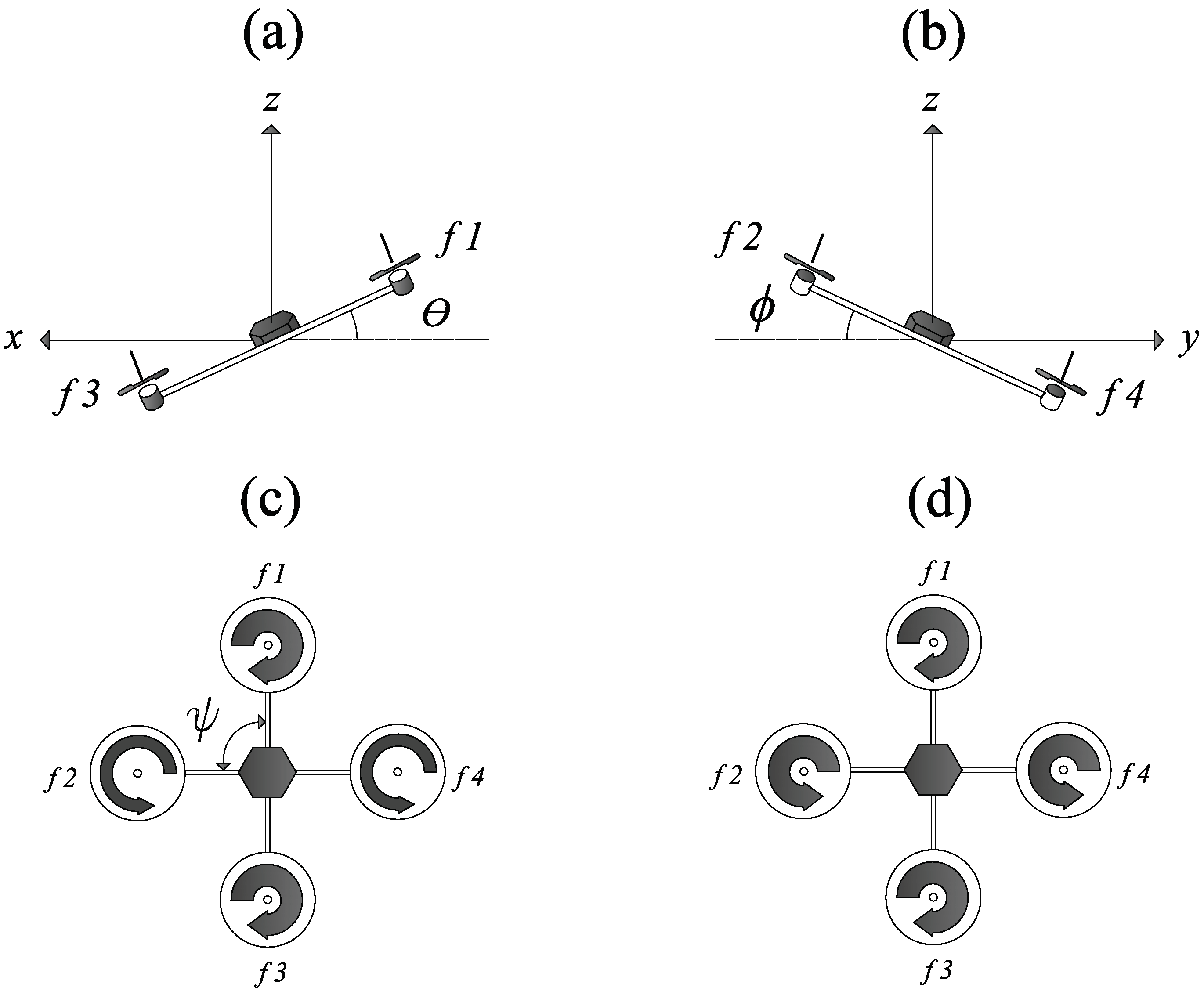
The movements that a quadrotor can perform, as shown in Figure 2, are as follows:
(a) Pitch movement allows the UAV to move along the x axis. To achieve this, the quadrotor needs to increase the angular velocity of rotor 1 (referred to as r 1 in Figure 1), reduce the angular velocity of rotor 3 ( r 3 ), and maintain a medium velocity in rotors 2 ( r 2 ) and 4 ( r 4 ), generating the torque τ θ . When these actions are performed, the UAV tilts, resulting in the generation of the angle θ (see Figure 2).
(b) Roll movement allows the drone to move along the y axis. For this movement, the quadrotor needs to increase the angular velocity of rotor 2 ( r 2 ), reduce the angular velocity of rotor 4 ( r 4 ), and maintain an intermediate velocity in rotors 1 ( r 1 ) and 3 ( r 3 ), generating the torque τ ϕ . When these actions are performed, the UAV tilts, resulting in the generation of the angle ϕ .
(c) Yaw movement occurs in the drone’s vertical plane. To produce this movement, the angular velocity of rotors 1 ( r 1 ) and 3 ( r 3 ) must be increased or decreased by the same amount, while the angular velocity of rotors 2 ( r 2 ) and 4 ( r 4 ) must be adjusted in the opposite direction, creating the torque τ ψ . Consequently, the quadrotor tends to rotate around its center of mass, generating the angle ψ (see Figure 2).
(d) By generating thrust, the drone can move along the z axis. This movement is achieved by maintaining the same angular speed (but not the same direction of rotation) in the four rotors of the quadrotor so that the thrust is greater than the gravitational force exerted on the aircraft.
By generating roll ϕ , yaw ψ and pitch θ angles, it is possible to modify the quadrotor’s spatial position. The previously described movements must be controlled simultaneously for the UAV to hover or follow specific trajectories assigned through a flight plan. It is important to note that even slight inclinations due to small changes in the UAV’s angles can complicate altitude control, thereby compromising the system’s stability.
Considering the above, it is helpful to define the mathematical representation of the drone’s orientation. The UAV’s non-linear dynamic model is extracted from [24,42], where it is completely detailed. This specifies that the UAV’s dynamics are defined by a combination of translational and simplified rotational dynamics, leading to the mathematical expressions presented below.
ψ ¨ = τ ψ I z z + ( I x x I y y ) ϕ ˙ θ ˙ I z z + ϕ ˙ θ ˙ , θ ¨ = τ θ I y y + ( I z z I x x ) ψ ˙ ϕ ˙ I y y ψ ˙ ϕ ˙ , ϕ ¨ = τ ϕ I x x + ( I y y I z z ) ψ ˙ θ ˙ I x x + ψ ˙ θ ˙ , x ¨ = S ψ S ϕ + C ψ S θ C ϕ u m , y ¨ = C ψ S ϕ + S ψ S θ C ϕ u m , z ¨ = C θ C ϕ u m g ,
The inertial parameters are represented by I x x , I y y , and I z z , and m signifies the mass of the quadrotor. The model’s inputs are defined according to (2).
u = f 1 + f 2 + f 3 + f 4 , τ ψ = f 1 + f 3 l f 2 + f 4 l , τ θ = ( f 1 f 3 ) l , τ ϕ = ( f 2 f 4 ) l ,
with l denoting the length of the UAV’s arms, g representing gravitational acceleration, and u representing the thrust that constitutes the input to translational dynamics, while the torques τ θ , τ ϕ , and τ ψ denote the inputs to rotational dynamics [24]. Lastly, the forces f i generated by each rotor that are incorporated into the quadrotor are defined as follows:
f i = k i ω i 2 , i = 1 , 2 , 3 , 4 .
From (3), it can be inferred that ω i signifies the angular velocity of each rotor and k i is a constant of proportionality.

3.2. UAV State-Space Model

The UAV quadrotor model mentioned earlier in (1) and (2) can be expressed in a state-space format as follows:
X ˙ = f ( X , U ) .
Subsequently, the state vector X = x 1 , x 2 , x 3 , , x 12 is defined as illustrated in Table 1.
Based on the previously defined state vector, the quadrotor’s non-linear state-space model can be represented as follows:
X ˙ = f X , U = x 2 x 4 x 6 a 1 + x 4 x 6 + b 1 u 2 x 4 x 2 x 6 a 2 x 2 x 6 + b 2 u 3 x 6 x 2 x 4 a 3 + x 2 x 4 + b 3 u 4 x 8 u x u 1 / m x 10 u y u 1 / m x 12 u z u 1 / m g ,
where
u 1 = u , u 2 = τ ϕ , u 3 = τ θ , u 4 = τ ψ , a 1 = ( I y y I z z ) I x x , a 2 = ( I z z I x x ) I y y , a 3 = ( I x x I y y ) I z z , b 1 = 1 / I x x , b 2 = 1 / I y y , b 3 = 1 / I z z , u x = S ψ S ϕ + C ψ S θ C ϕ = ( S x 5 S x 1 + C x 5 S x 3 C x 1 ) , u Y = C ψ S ϕ + S ψ S θ C ϕ = ( C x 5 S x 1 + S x 5 S x 3 C x 1 ) , u Z = C θ C ϕ = ( C x 3 C x 1 ) .
The values presented in Table 2 are utilized for the numerical simulation of the UAV.

3.3. Linearization of the UAV Mathematical Model

The non-linear quadrotor model defined by Equations (5) and (6) has been linearized around the equilibrium point P e = ϕ , θ , ψ , z ¨ = ( 0 , 0 , 0 , 0 ) . Consequently, the linear version of the non-linear model is derived and presented in the general state-space format defined in Equation (7).
X ˙ t = AX t + BU t , Y t = CX t + DU t ,
where U ( t ) R m is the input vector, Y ( t ) R p is the output vector, and X ( t ) R n is the state vector. A R n × n is the system matrix, B R n × m is the input matrix, C R p × n is the output matrix, and D R n × q is the input distribution matrix. The coefficients of the matrices A , B , C , and D are obtained from the linearized state-space model expressed in the continuous-time domain, as shown in (9).
An alternative way of expressing the linear dynamic model of the UAV is through the transfer function matrix G UAV ( s ) obtained by performing the matrix operations defined by (8). This version of the linear model could be useful for the design of control systems for the hovering flight of a drone.
G UAV ( s ) = C s I A 1 B .
A = f X P e = 0 1 0 0 0 0 0 0 0 0 0 0 0 0 0 0 0 0 0 0 0 0 0 0 0 0 0 1 0 0 0 0 0 0 0 0 0 0 0 0 0 0 0 0 0 0 0 0 0 0 0 0 0 1 0 0 0 0 0 0 0 0 0 0 0 0 0 0 0 0 0 0 0 0 0 0 0 0 0 1 0 0 0 0 0 0 g 0 0 0 0 0 0 0 0 0 0 0 0 0 0 0 0 0 0 1 0 0 g 0 0 0 0 0 0 0 0 0 0 0 0 0 0 0 0 0 0 0 0 0 0 1 0 0 0 0 0 0 0 0 0 0 0 0 , B = f U P e = 0 0 0 0 0 l / I x x 0 0 0 0 0 0 0 0 l / I y y 0 0 0 0 0 0 0 0 l / I z z 0 0 0 0 0 0 0 0 0 0 0 0 0 0 0 0 0 0 0 0 1 / m 0 0 0 , C = I 12 × 12 , D = 0 12 × 4 .

4. Main Results

This section presents the classical order control system for quadrotor hovering (COCSH), which has been developed using parameters obtained from the dynamic matrices of the quadrotor’s linear model, as defined in the previous section. Next, we adapt and modify the COCSH to include a fractional approach, leading to the creation of a Fractional Order Control System (FOCSH). This development serves as the main contribution of this research.

4.1. Classical Order Control System Design

The classical order control system for hovering drone flight (COCSH) has been designed as detailed in Figure 3, taking into consideration the reduced dynamics model expressed by (1) and (2), or alternatively, by (5) and (6). The main purpose of this system is to generate the appropriate control actions for the quadrotor to reach and maintain hovering at a desired position in three-dimensional space with the coordinates ( x r e f , y r e f , z r e f ), and with a desired orientation ψ r e f , thus ensuring the asymptotic convergence to zero of the errors e y , e x , e ϕ , e θ , e ψ , and e z . As shown in this figure, the COCSH consists of six proportional–integral–derivative (PID) controllers, whose control actions are described by the expressions denoted in (10). These controllers are coupled and organized in such a way that they form two feedback loops: there are inner-loop controllers and outer-loop controllers. Based on the latter expression, it is important to highlight that k p y , k p x , k p ϕ , k p θ , k p ψ , k p z , k i y , k i x , k i ϕ , k i θ , k i ψ , k i z , k d y , k d x , k d ϕ , k d θ , k d ψ , and k d z R are constant gains that have been calculated by tuning the PID controllers that constitute the COCSH.
ϕ r e f ( t ) = k p y e y ( t ) + k i y 0 t e y ( t ) d t + k d y d e y ( t ) d t , θ r e f ( t ) = k p x e x ( t ) + k i x 0 t e x ( t ) d t + k d x d e x ( t ) d t , r o l l ( t ) = k p ϕ e ϕ ( t ) + k i ϕ 0 t e ϕ ( t ) d t + k d ϕ d e ϕ ( t ) d t , p i t c h ( t ) = k p θ e θ ( t ) + k i θ 0 t e θ ( t ) d t + k d θ d e θ ( t ) d t , y a w ( t ) = k p ψ e ψ ( t ) + k i ψ 0 t e ψ ( t ) d t + k d ψ d e ψ ( t ) d t , t h r u s t ( t ) = k p z e z ( t ) + k i z 0 t e z ( t ) d t + k d z d e z ( t ) d t .
It is worth noting that, alongside the translation and rotation dynamics of the aircraft, the dynamics of its actuators have also been taken into account for the COCSH design. In this context, these rotor-type motors ( r 1 , r 2 , r 3 , r 4 ), which are integrated into the drone, have been modeled as direct current (DC) motors. To simplify the control system’s design, the dynamics of each rotor of the drone have been modeled as those of a DC motor and approximated to a first-order dynamic system following the methodology outlined in [43]. This results in the transfer function R i ( s ) , defined by (11), where the angular velocity ω i is considered the output and the excitation voltage V a the input.
R i ( s ) = ω i ( s ) V a ( s ) = 0.975 0.25 s + 1 .
Considering the UAV model parameters described in Table 2 and the equilibrium point P e = ϕ , θ , ψ , z ¨ = ( 0 , 0 , 0 , 0 ) , and taking the Laplace transform, with initial conditions set to zero, of the expressions that define the UAV’s reduced rotational dynamics implicit in (1), the following second-order transfer functions implicit in (12)–(15) are obtained. These are used to tune all PID controllers that are not part to the outer loop (see Figure 3). These transfer functions are not suitable for describing abrupt dynamics in the UAV, as they have been derived using the small-angle approximation denoted by the equilibrium point P e . It is worth noting that in this transfer function, the variables ϕ , θ , ψ , and z are considered as outputs, while the variables u 2 , u 3 , u 4 , and u 1 (as denoted by expression (6)), are considered as inputs, respectively. In this context, for the design of the PID controllers that are not part of the outer loop of the UAV hover control system (COCSH), it is presumed that the approximate orientation and elevation dynamics are interconnected with the actuator dynamics in a cascaded manner; in other words, it is assumed that the overall dynamics, which take into account the effects of the actuators, can be roughly represented as the product of the transfer functions displayed below:
G U A V ϕ ( s ) = R i ( s ) G ϕ a p p r o x ( s ) = 0.975 0.25 s + 1 0.28 0.0116 s 2 ,
G U A V θ ( s ) = R i ( s ) G θ a p p r o x ( s ) = 0.975 0.25 s + 1 0.28 0.0116 s 2 ,
G U A V ψ ( s ) = R i ( s ) G ψ a p p r o x ( s ) = 0.975 0.25 s + 1 0.28 T q 0.0232 s 2 ,
G U A V z ( s ) = R i ( s ) G z a p p r o x ( s ) = 0.975 0.25 s + 1 1 1.4 s 2 .
To carry out the design of the PID controllers that do not belong to the outer loop, the transfer functions defined by (12)–(15) are used. These are considered individually as a part that requires control and as single-input single-output (SISO) systems. Thus, a PID controller is tuned for each of these expressions, resulting in four closed-loop systems with negative feedback, where the controllers represented by the transfer functions indicated in (18)–(21) are employed. It is important to mention that expressions (16)–(21) correspond to the Laplace transforms of the expressions denoted by (10), considering initial conditions equal to zero.
P I D y ( s ) = Φ r e f ( s ) E y ( s ) = k d y s 2 + k p y k d y s + k i y k d y s = k y s 2 + ( a y + b y ) s + a y b y s ,
P I D x ( s ) = Θ r e f ( s ) E x ( s ) = k d x s 2 + k p x k d x s + k i x k d x s = k x s 2 + ( a x + b x ) s + a x b x s ,
P I D ϕ ( s ) = R o l l ( s ) E ϕ ( s ) = k d ϕ s 2 + k p ϕ k d ϕ s + k i ϕ k d ϕ s = k ϕ s 2 + ( a ϕ + b ϕ ) s + a ϕ b ϕ s ,
P I D θ ( s ) = P i t c h ( s ) E θ ( s ) = k d θ s 2 + k p θ k d θ s + k i θ k d θ s = k θ s 2 + ( a θ + b θ ) s + a θ b θ s ,
P I D ψ ( s ) = Y a w ( s ) E ψ ( s ) = k d ψ s 2 + k p ψ k d ψ s + k i ψ k d ψ s = k ψ s 2 + ( a ψ + b ψ ) s + a ψ b ψ s ,
P I D z ( s ) = T h r u s t ( s ) E z ( s ) = k d z s 2 + k p z k d z s + k i z k d z s = k z s 2 + ( a z + b z ) s + a z b z s .
To carry out the design of the PID controllers in the outer loop, the transfer functions defined by (22) and (23) are used. These expressions represent to the closed-loop transfer functions that describe two of the four feedback control systems previously discussed. When designing these outer-loop controllers, each of these closed-loop transfer functions are considered individually as the part requiring control and treated as single-input single-output (SISO) systems. Thus, a PID controller is adjusted for each of these expressions, creating two closed-loop systems with negative feedback, utilizing the controllers defined by the transfer functions represented in (16) and (17).
G P I D ϕ G U A V ϕ ( s ) = Φ ( s ) Φ r e f ( s ) = k ϕ ( s + a ϕ ) ( s + b ϕ ) s 0.273 0.0029 s 3 + 0.0116 s 2 1 + k ϕ ( s + a ϕ ) ( s + b ϕ ) s 0.273 0.0029 s 3 + 0.0116 s 2 ,
G P I D θ G U A V θ ( s ) = Θ ( s ) Θ r e f ( s ) = k θ ( s + a θ ) ( s + b θ ) s 0.273 0.0029 s 3 + 0.0116 s 2 1 + k θ ( s + a θ ) ( s + b θ ) s 0.273 0.0029 s 3 + 0.0116 s 2 .
It is important to mention that to tune all the PID controllers that make up the control system for the drone’s hovering flight (COCSH), the root locus technique in the continuous-time domain has been used. To accomplish this, unit step-type reference signals have been utilized for the sake of simplicity.

4.2. Fractional-Order Control System Design

In this section, the classical order control system for hovering drone flight (COCSH) is modified by adapting it to the Riemann–Liouville fractional calculus approach. This modification allows for the development of a new control system called the Fractional-Order Control System for hovering drone flight (FOCSH). This reinforces the advantages that can be observed and identifies potential enhancements in the transient response of the FOCSH in comparison to the COCSH. To validate this modification, the next section provides numerical simulations applied to a quadrotor UAV model, with the results assessed using performance indices. In order to adapt the COCSH to the proposed FOCSH, the first step involves considering the following definitions of fractional calculus:
Definition 1.
The iterated Cauchy integral of order n c N is defined by the following expression [42]:
I x n c a C f ( x ) = 1 n c 1 ! a x x t n c 1 f ( t ) d t , I x 0 a c f ( x ) = f ( x ) .
Definition 2.
Euler’s Gamma function is one that generalizes the factorial concept and extends it to the real-number set. This function is described by the following expression:
Γ n = a t n 1 e t d t , n R .
The following expressions define some of the fundamental properties of Euler’s Gamma function [42]:
Γ n + 1 = n Γ n , Γ n = n 1 ! , Γ 1 = Γ 2 = 1 , Γ 1 2 = π .
When taking into account the definition and properties of Euler’s Gamma function within the context of the Cauchy iterated integral, the fractional-order integral operator outlined in Definition 3 is established.
Definition 3.
The Riemann–Liouville integral operator of order α 0 , when a 0 , is defined as
I x α a R L f ( x ) = 1 Γ ( α ) a x x t α 1 f ( t ) d t , I x 0 a R L f ( x ) = f ( x ) ,
where Γ ( α ) is Euler’s Gamma function and α R [42].
In the next step, taking into account the earlier definitions and the characteristics of the Gamma function, all PID controllers forming the Classical Order Control System (COCSH) for hovering drone flight are adjusted to modify their integral effect, as outlined in (27), within the FOCSH, as illustrated in (28).
ϕ r e f ( t ) = k p y e y ( t ) + k i y I t α 0 R L e y ( t ) + k d y d e y ( t ) d t , θ r e f ( t ) = k p x e x ( t ) + k i x I t α 0 R L e x ( t ) + k d x d e x ( t ) d t , r o l l ( t ) = k p ϕ e ϕ ( t ) + k i ϕ I t α 0 R L e ϕ ( t ) + k d ϕ d e ϕ ( t ) d t , p i t c h ( t ) = k p θ e θ ( t ) + k i θ I t α 0 R L e θ ( t ) + k d θ d e θ ( t ) d t , y a w ( t ) = k p ψ e ψ ( t ) + k i ψ I t α 0 R L e ψ ( t ) + k d ψ d e ψ ( t ) d t , t h r u s t ( t ) = k p z e z ( t ) + k i z I t α 0 R L e z ( t ) + k d z d e z ( t ) d t .
Finally, for the implementation of the FOCSH, the classical order controllers of the control scheme shown in Figure 3 are replaced by fractional-order PID controllers, whose control actions are described by (28). It is important to highlight that the gains of the controllers that make up the FOCSH are the same as those obtained by tuning the COCSH controllers.

5. Validation and Discussion of the Results

The results of the numerical simulation carried out in MATLAB R2022b® software are presented in this section, comparing the COCSH and the FOCSH applied to the non-linear dynamic model of a UAV given by (5) and (6), as described in Section 3. For this purpose, the UAV model parameters listed in Table 2 are considered. These simulations are designed to demonstrate the performance and possible enhancements in the transient behavior of the closed-loop response when the proposed COCSH approach is utilized, and then compare it with the FOCSH performance, with both approaches involving the UAV performing hovering maneuvers. Therefore, to validate the results, a performance index such as the mean squared error (MSE) is proposed.

5.1. Closed-Loop Response Comparison for UAV Hover Flight Using COCSH vs. FOCSH

To evaluate the advantages of the closed-loop response of the FOCSH compared to the COCSH when the quadrotor performs hover movements, we set out to conduct a set of numerical simulations in which a simulation time of 90 s is established, considering an iteration step of Δ t = 25 miliseconds, with the aim of having convergence with the continuous-time controllers’ design technique. It is important to highlight that in these numerical simulations, both control systems are coupled with the non-linear dynamic model of the UAV, with the aim of enabling the quadrotor to reach its desired orientation, ψ r e f , and maintain hovering in two desired positions in three-dimensional space ( P r e f 1 and P r e f 2 ), whose coordinates, expressed in meters, are described by the following expression:
P r e f 1 = x r e f 1 , y r e f 1 , z r e f 1 = 11 , 11 , 1.3 , P r e f 2 = x r e f 2 , y r e f 2 , z r e f 2 = 1 , 1 , 13.3 .
The COCSH and FOCSH control systems have been designed to enable the drone to reach points P r e f 1 and P r e f 2 in three-dimensional space, despite disturbances arising from various sources, such as atmospheric turbulence, sudden changes in payload, and gusts of wind.
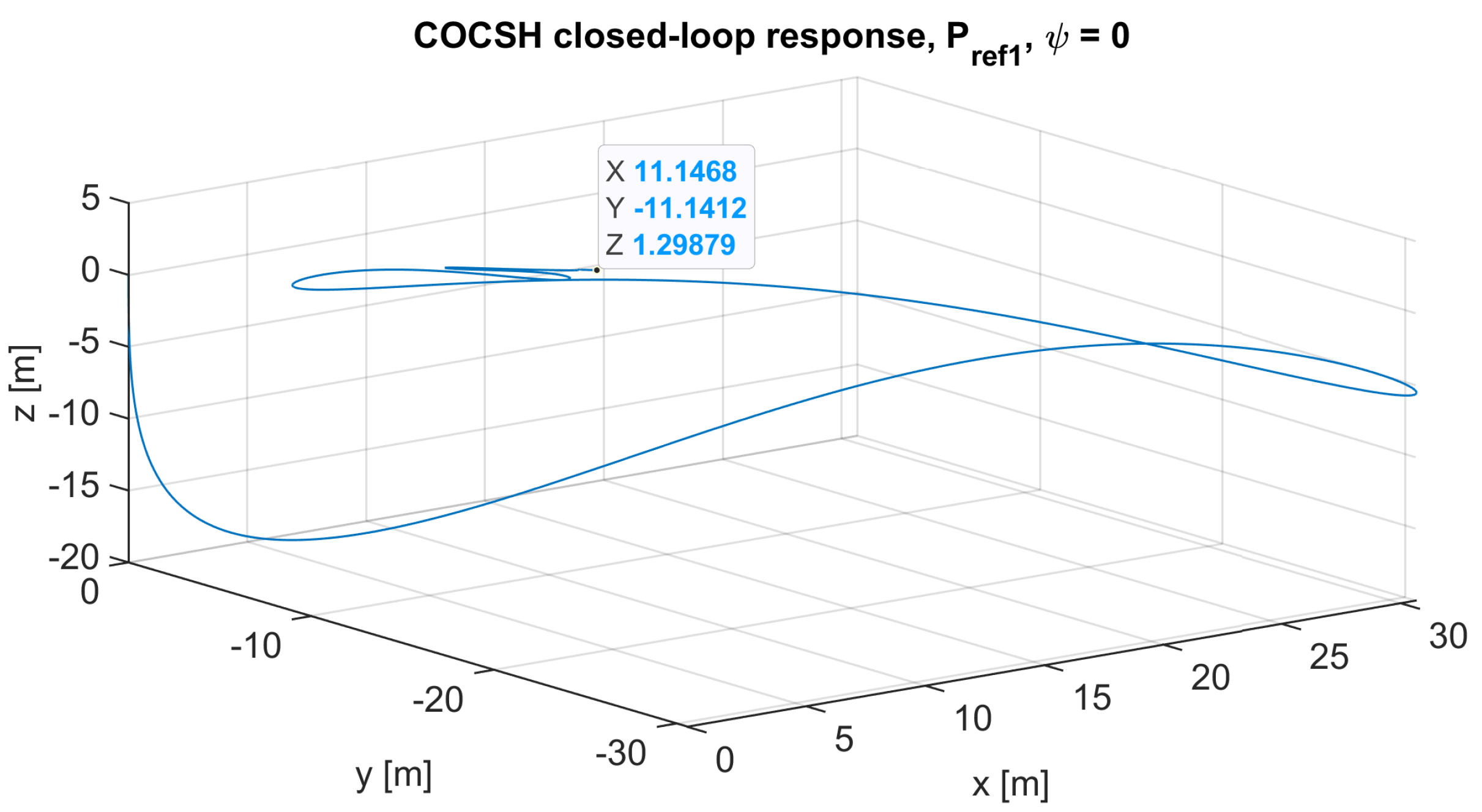
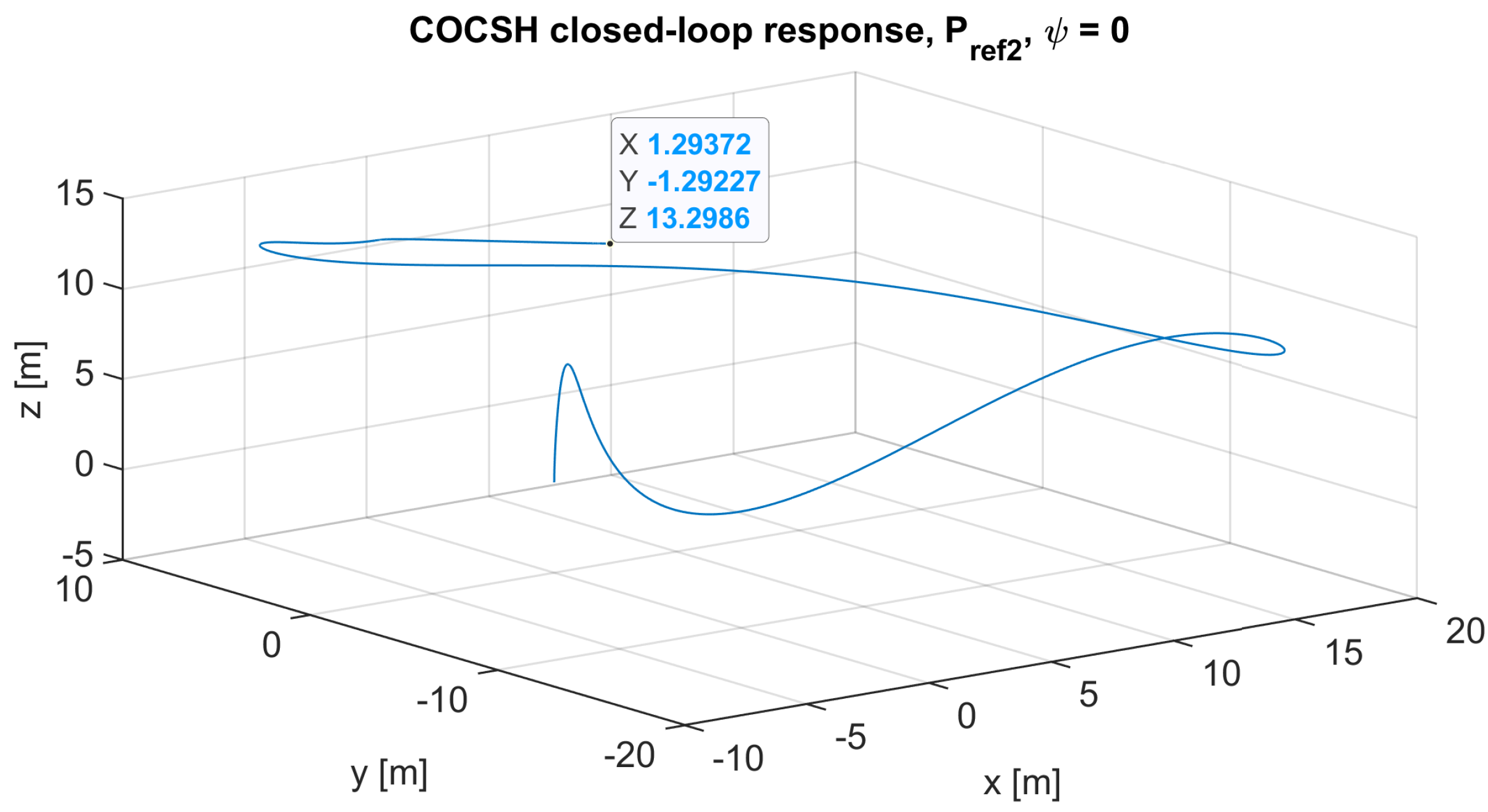
The closed-loop response of the COCSH, when the drone hovers with an orientation of ψ = 0 radians at points P r e f 1 and P r e f 2 in three-dimensional space, is shown in Figure 4 and Figure 5, respectively.
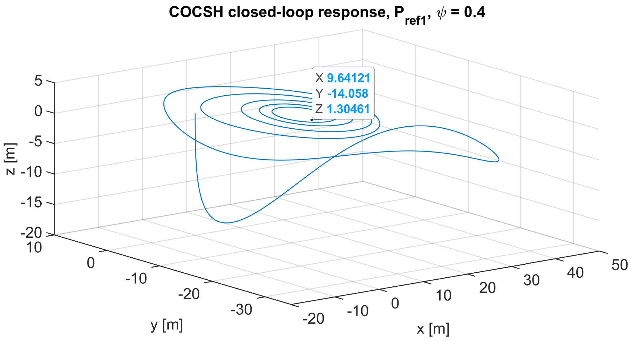
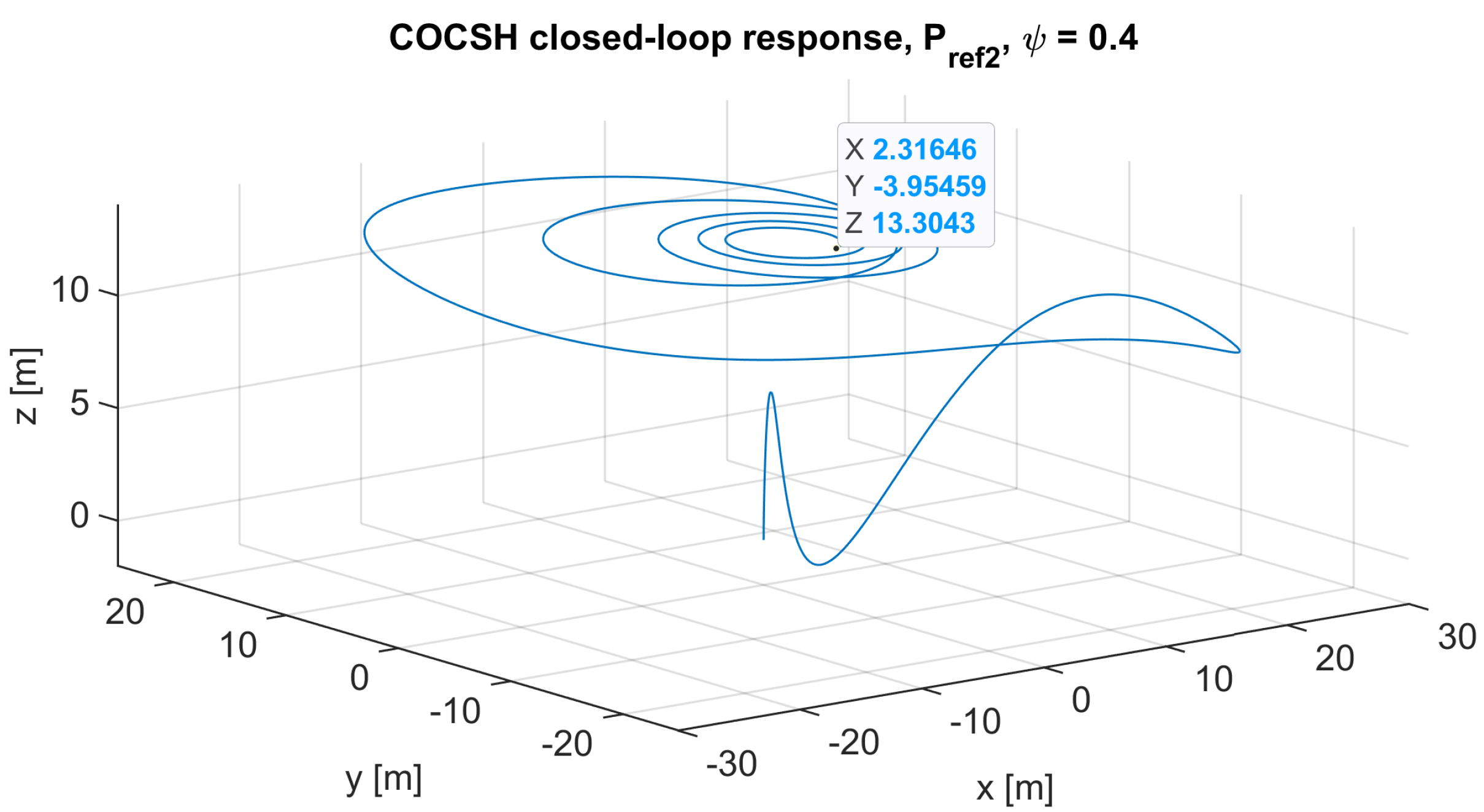
The closed-loop response of the COCSH when the drone hovers with an orientation of ψ = 0.4 radians at points P r e f 1 and P r e f 2 in three-dimensional space can be seen in Figure 6 and Figure 7, respectively.
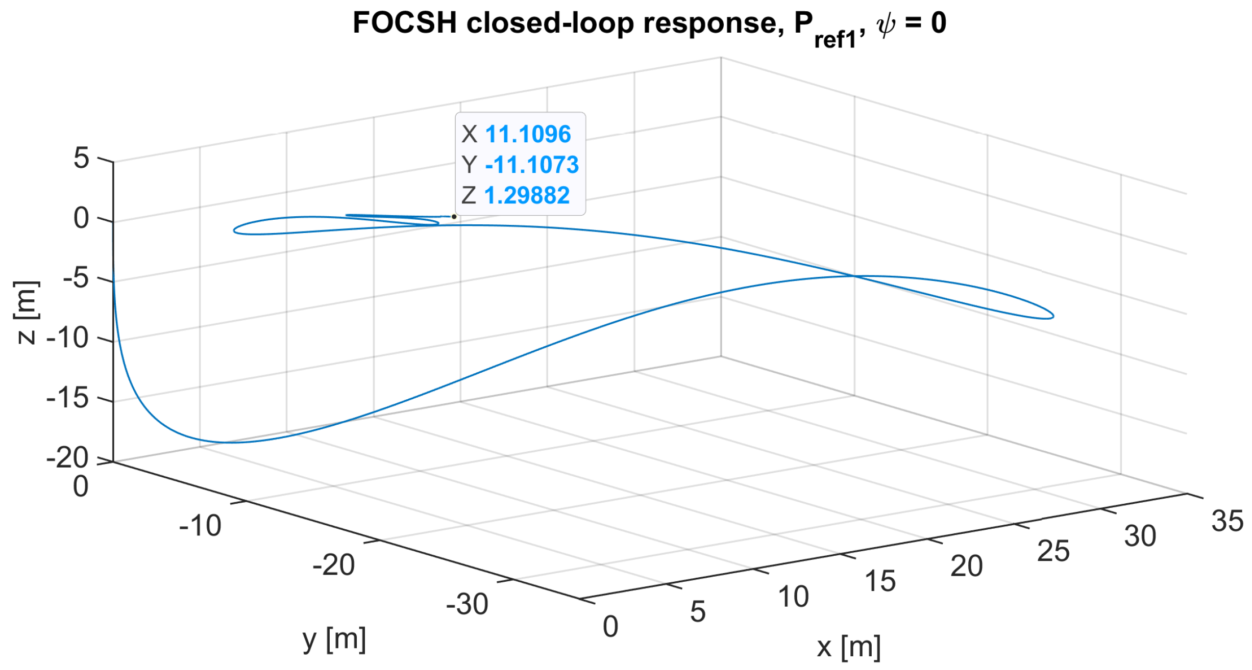
The closed-loop response of the FOCSH when the drone hovers with an orientation of ψ = 0 radians at points P r e f 1 and P r e f 2 in three-dimensional space can be seen in Figure 8 and Figure 9, respectively. For both points in three-dimensional space, α = 0.99 has been used.
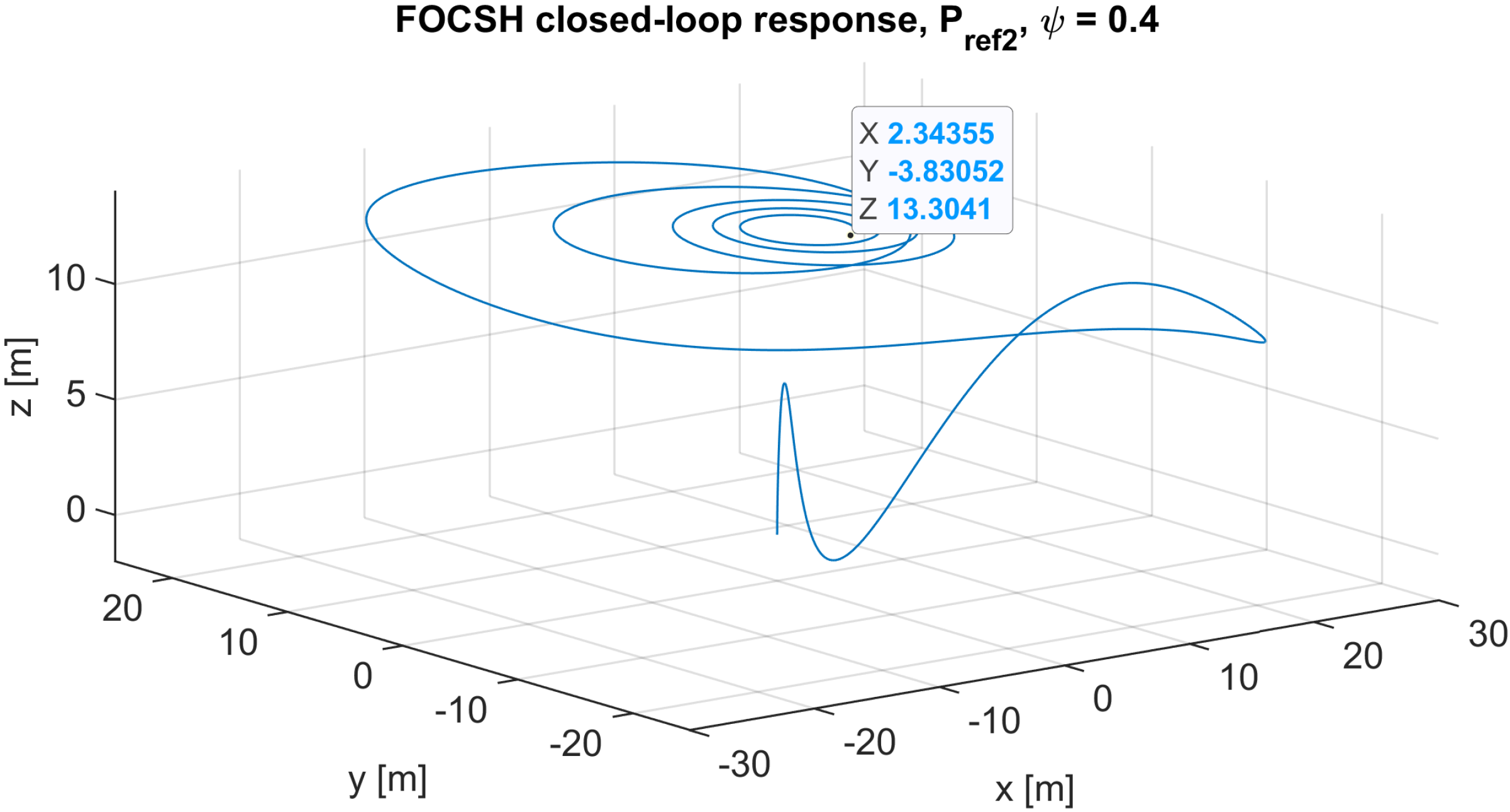
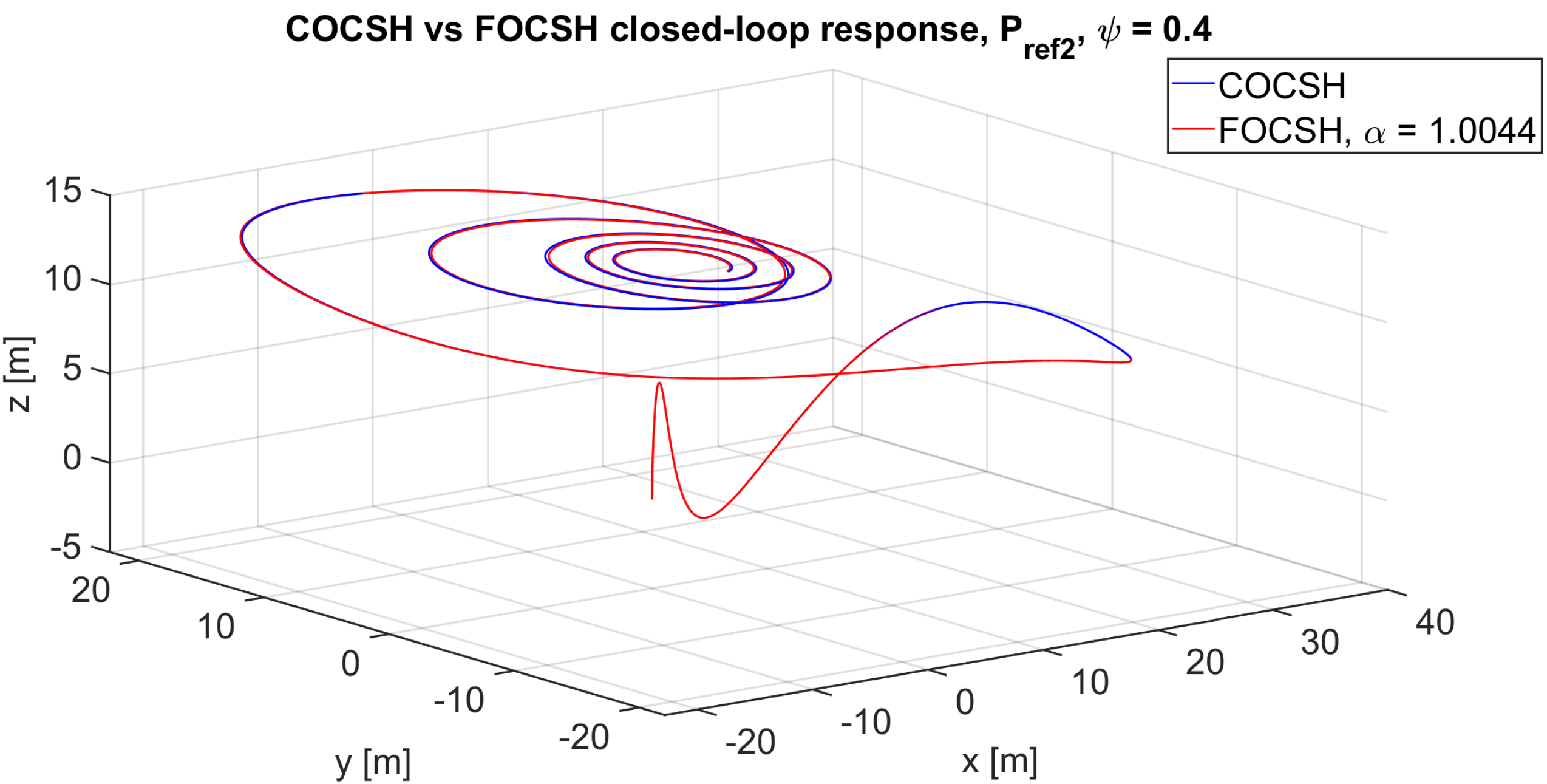
The closed-loop response of the FOCSH when the drone hovers with an orientation of ψ = 0.4 radians at points P r e f 1 and P r e f 2 in three-dimensional space can be seen in Figure 10 and Figure 11, respectively. It is important to mention that for point P r e f 1 , α = 1.098 was used, while for point P r e f 2 α = 1.0044 was used.

5.2. Discussion

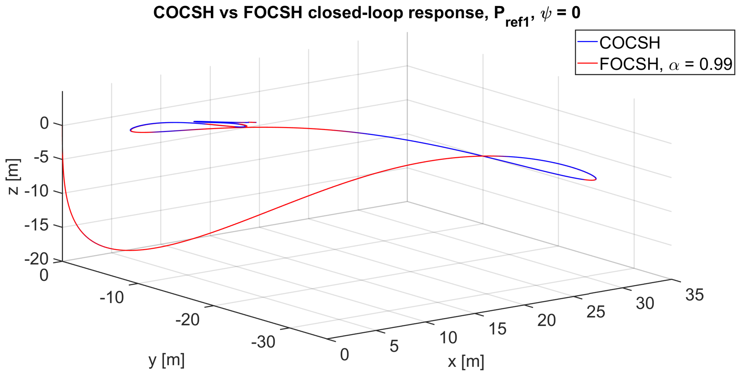
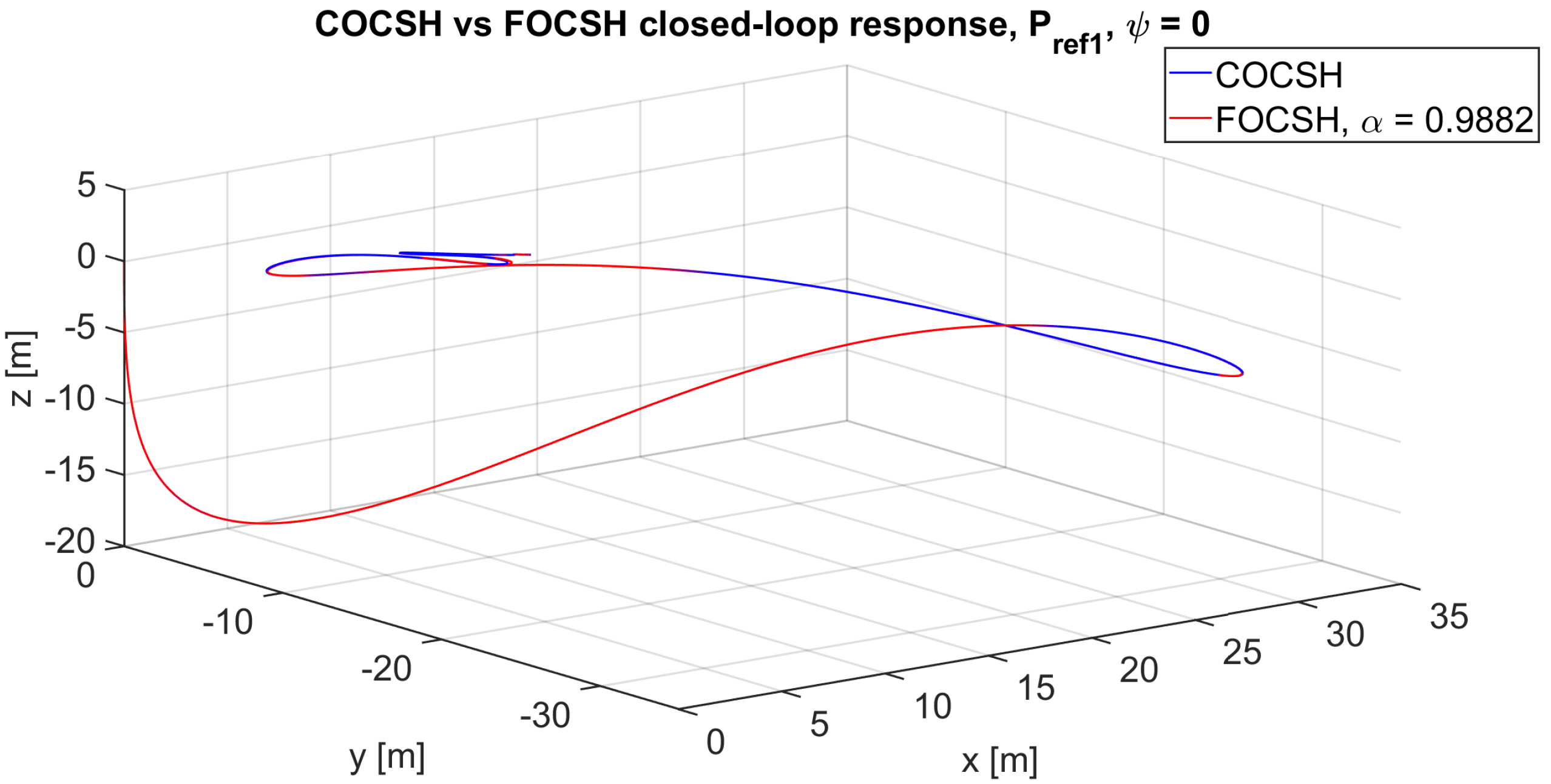
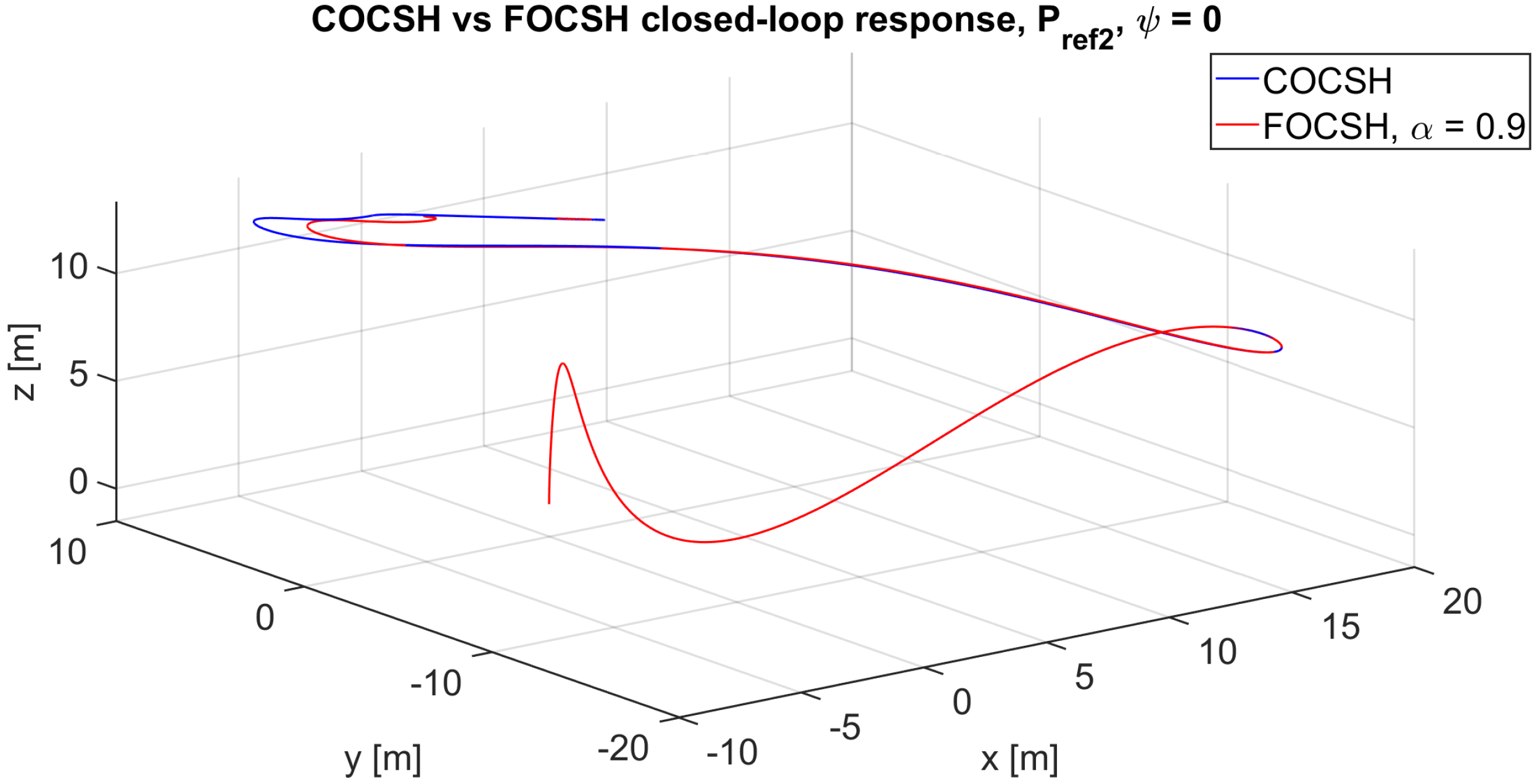
In order to highlight one of the contributions of this paper, Figure 12, Figure 13, Figure 14, Figure 15, Figure 16, Figure 17, Figure 18 and Figure 19 present the superimposed results of the closed-loop response for the hovering flight of the drone at points P r e f 2 and P r e f 2 in three-dimensional space, conducted using the COCSH and the FOCSH. These figures demonstrate that both closed-loop responses, depending on the α parameter (used only for the FOCSH implementation), exhibit similar dynamics and convergence times. However, in most cases, the FOCSH enables the drone to reach points P r e f 1 and P r e f 2 more quickly (see Figure 4, Figure 5, Figure 6, Figure 7, Figure 8, Figure 9, Figure 10 and Figure 11). Therefore, it is necessary to use performance indices that describe the efficiency of the classical and fractional approaches. In this context, we propose quantitatively and qualitatively assessing the drone hovering performance of the control systems through the mean squared error (MSE). In this sense, a comprehensive analysis of the evolution of the mean squared error of the drone’s ability to reach the final position in a three-dimensional space during stationary flight (hovering) was carried out. The MSE was calculated with the aim of evaluating the accuracy and stability of both control systems, thus allowing us to denote the improvements in the closed-loop responses. This analysis allows for quantifying the drone’s deviations from its target position, providing a comprehensive measure of the controller’s performance in terms of positional stability under stationary conditions.
To carry out this analysis, a recursive MSE calculation scheme was designed in order to obtain a temporary mean squared error throughout the drone’s stabilization process, as well as a global measure of the system’s behavior. The accuracy of the final hovering position (rather than the trajectory) allows the evaluation of the controller’s performance in its ability to precisely reach and maintain the desired position under various operational conditions and external disturbances. In this way, the calculation of the MSE becomes a fundamental tool in validating the control system’s effectiveness in real-world environments and to optimize its performance for future applications.
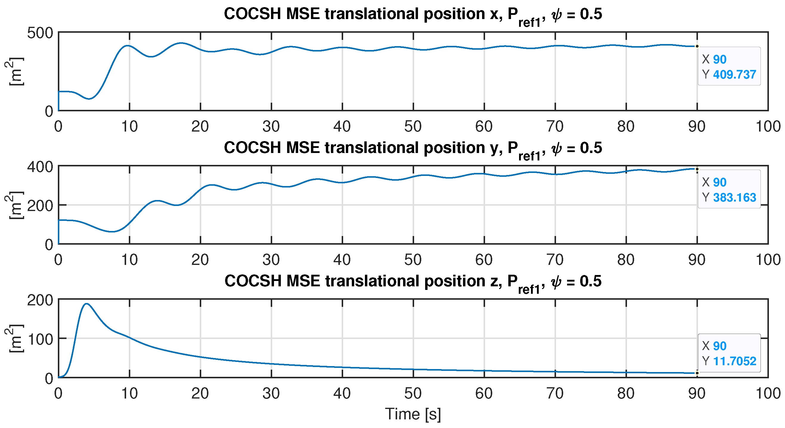
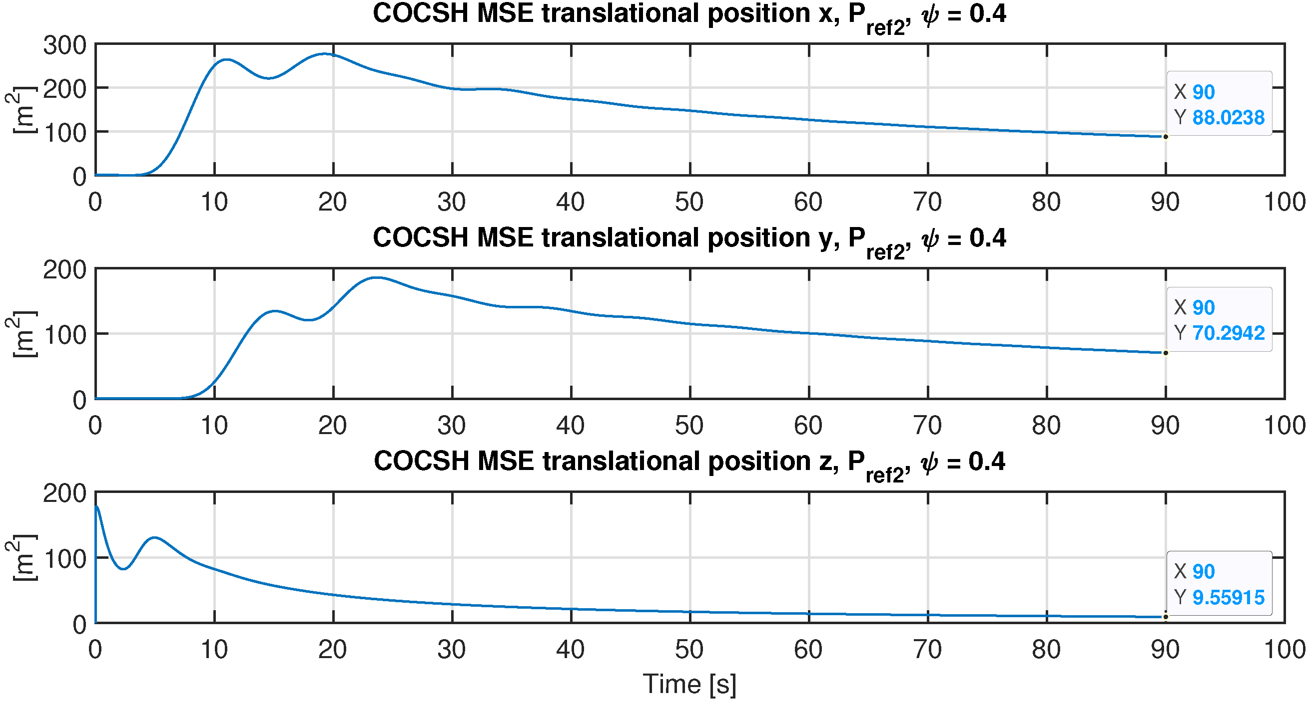
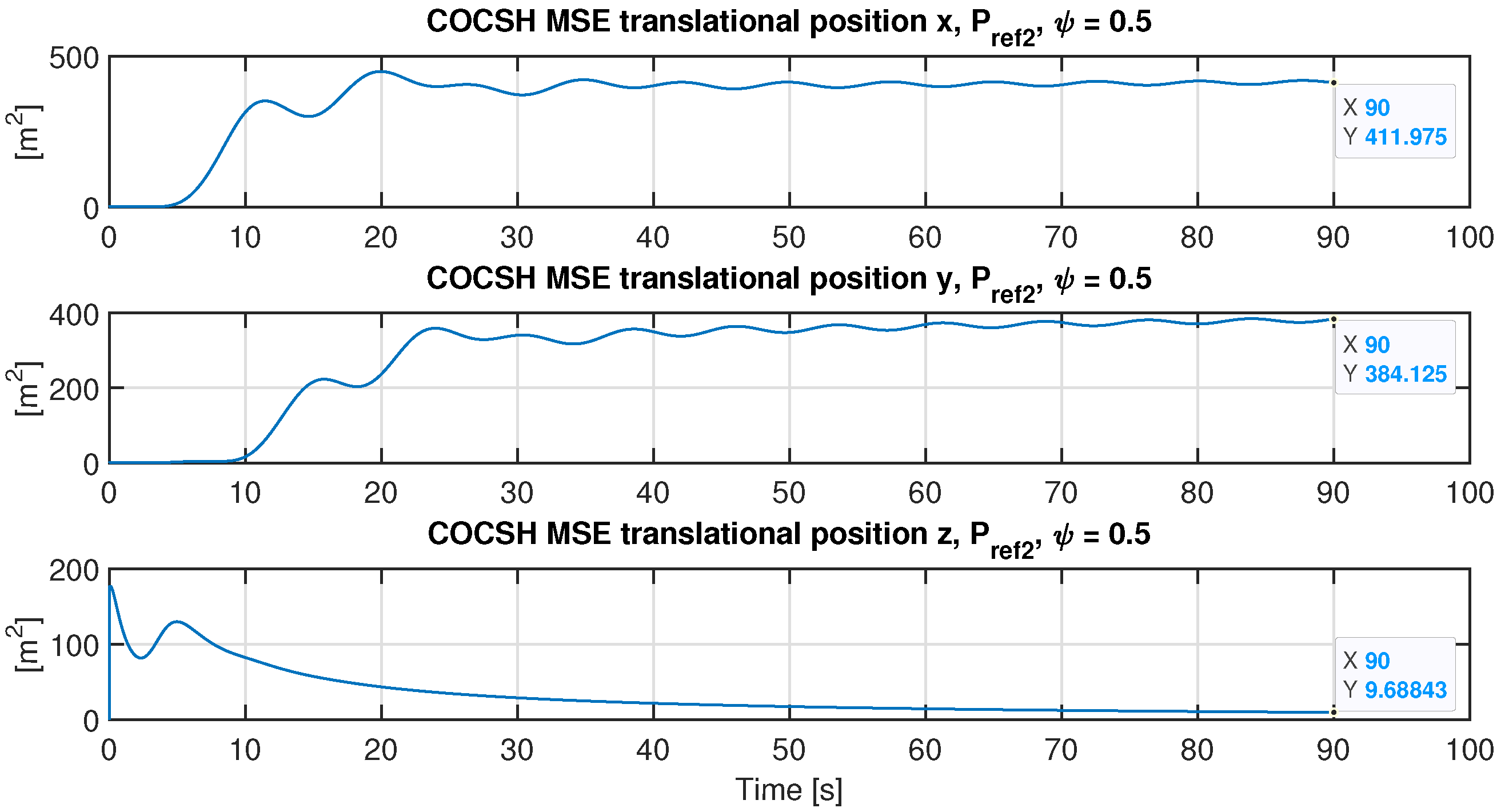
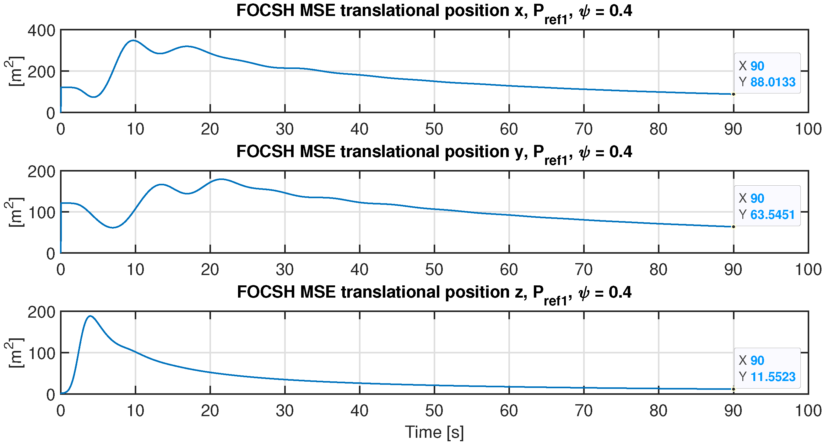
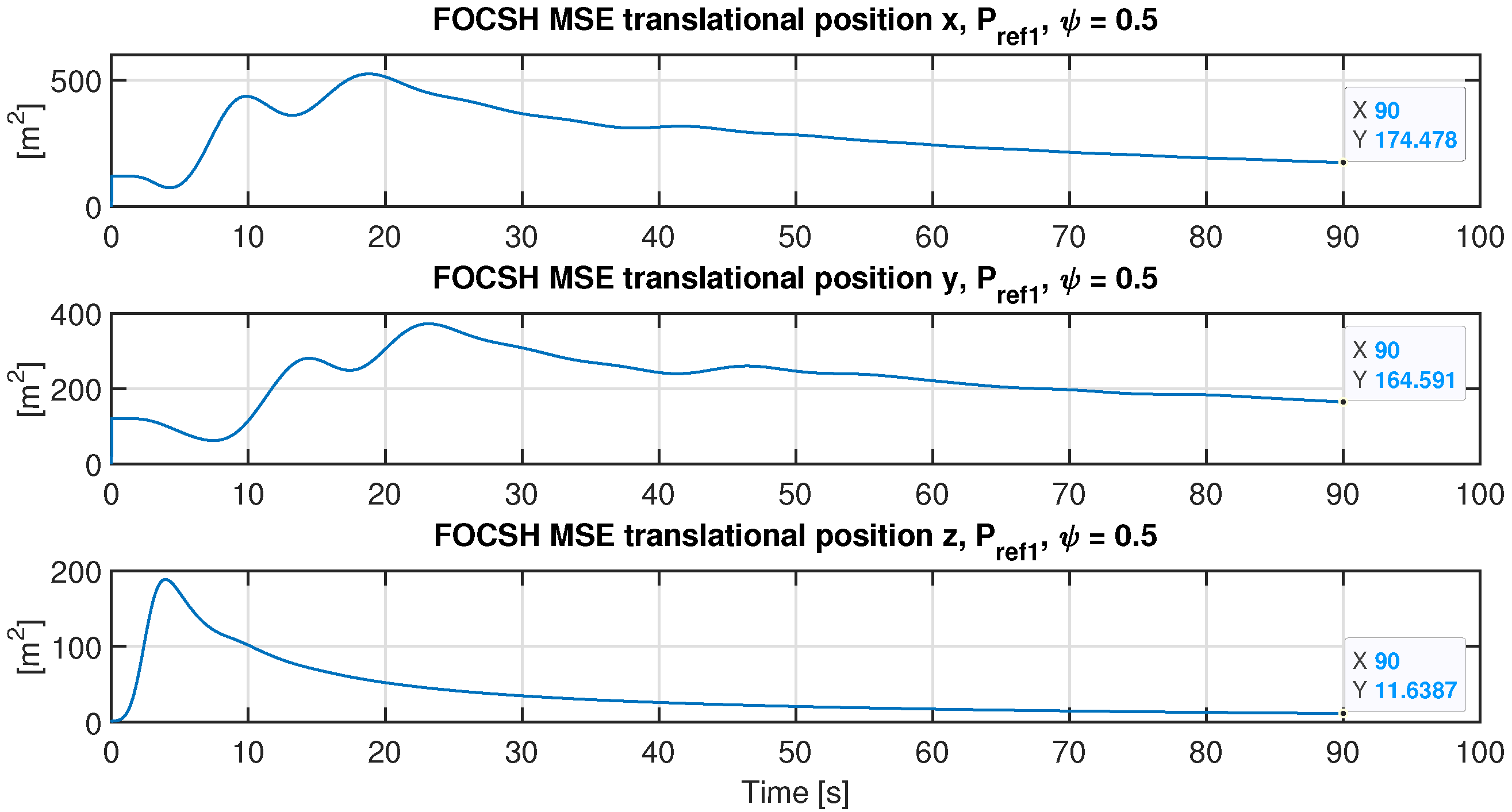
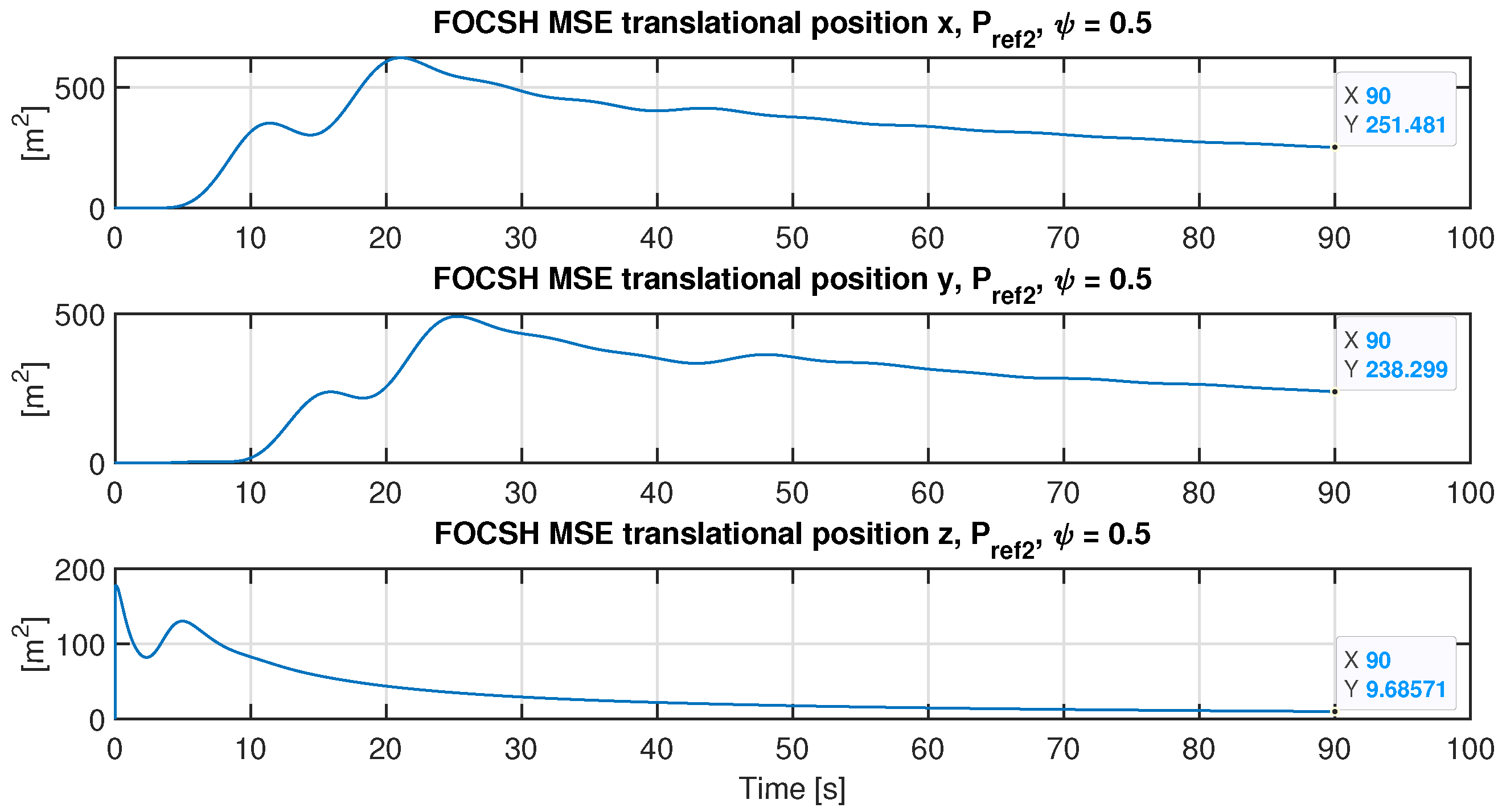
Figure 20, Figure 21, Figure 22, Figure 23, Figure 24, Figure 25, Figure 26, Figure 27, Figure 28, Figure 29, Figure 30, Figure 31, Figure 32 and Figure 33 show the dynamics of the MSE performance indices of the closed-loop responses when the drone hovers at the three-dimensional-space points P r e f 1 and P r e f 2 using the COCSH and FOCSH control systems. These indices serve as a quantitative test of the drone’s convergence quality, where a small MSE magnitude indicates a minor error in the translational positions when the drone hovers at points P r e f 1 and P r e f 2 . Additionally, to indicate the best performance in the closed-loop response between the COCSH and the FOCSH, an indicator of the Best Quality of the Closed-Loop Response (BQC-LR) as described in Table 3 is proposed. This table specifies that the MSE is lower in all cases for the proposed FOCSH approach.
Based on Table 3, it can be inferred that in every case, the mean squared error (MSE) is higher for the COCSH approach than for the proposed FOCSH approach. Furthermore, considering the BQC-LR indicator, which denotes the best control system with a special character (*), it is possible to conclude that the FOCSH performs better in hover flight across all cases, since its MSE performance index is lower than that of the COCSH.
Finally, it is important to mention that through an analysis based on the simulation results shown in Figure 4, Figure 5, Figure 6, Figure 7, Figure 8, Figure 9, Figure 10, Figure 11, Figure 12, Figure 13, Figure 14, Figure 15, Figure 16, Figure 17, Figure 18 and Figure 19 and the MSE performance indices shown in Figure 20, Figure 21, Figure 22, Figure 23, Figure 24, Figure 25, Figure 26, Figure 27, Figure 28, Figure 29, Figure 30, Figure 31, Figure 32 and Figure 33, which have been obtained by coupling the COCSH and FOCSH control systems to the non-linear model of the UAV described by (1), (2), (5) and (6), it can be established that from the improvement in the closed-loop response of the FOCSH compared to the COCSH, the selection of the alpha parameter could be made considering the following two proposed criteria:
The selection of the α parameter for FOCSH implementation should be made according to expression (30), when the model is described by (1), (2), (5) and (6), due to small values of ψ tending to behave in a linear manner, like the model described by (7)–(9), thus enhancing the controller’s robustness.
α = lim Δ α 0 1 Δ α .
The selection of the α parameter for FOCSH implementation should be made according to expression (31), when the model is described by (1), (2), (5) and (6), due to large values of ψ tending to behave in a non-linear manner, thus enhancing the controller’s robustness.
α = lim Δ α 0 1 + Δ α .
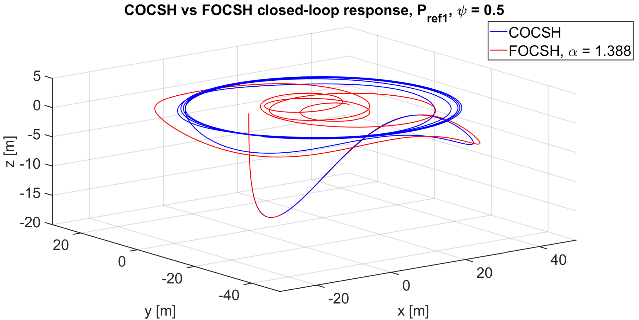
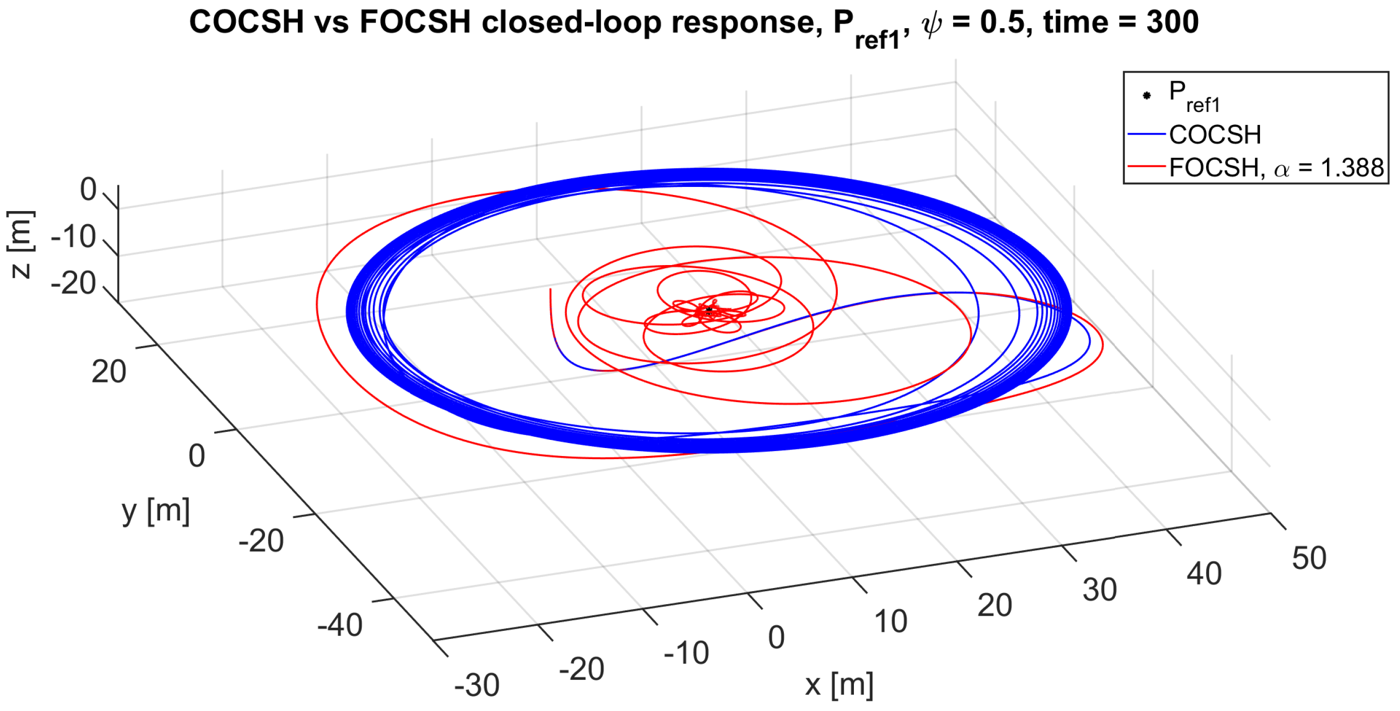
To denote the ability of the FOCSH to handle non-linearities and the improvement in its closed-loop response, Figure 34 and Figure 35 are presented, in which a simulation time of 300 s is considered. Figure 34 shows a comparison of the closed-loop response between COCSH and FOCSH when the drone reaches a hover at point P r e f 1 , with a desired orientation ψ = 0.5 radians (rotation around its vertical axis). When analyzing the drone’s trend over a simulation time of 300 s, it can be observed that the elevation control along the z axis works for both COCSH and FOCSH. However, in the case of the COCSH, the drone follows an orbital flight around the reference point P r e f 1 , which it is unable to reach as the simulation progresses. In contrast, for the FOCSH, with a value of α = 1.388, this orbital flight converges around the reference point P r e f 1 .
A similar behavior is shown in Figure 35 when the drone reaches a hover at point P r e f 2 with a desired orientation ψ = 0.5 radians. In the course of a simulation time of 300 s, it can be seen that in the case of the COCSH, the drone once again follows an orbital flight around the reference point P r e f 2 without reaching it as the simulation progresses. In contrast, for the FOCSH, with α = 1.294, this orbital flight converges towards the reference point P r e f 2 .
It is important to emphasize that the expressions defining the controllers that constitute the COCSH are described by Equations (10)–(23). Furthermore, it is emphasized that these have been tuned using the root locus technique in the continuous-time domain for practical and straightforward purposes. Consequently, these have been adapted to the fractional approach using the same gains to conduct a fair comparison with classical controllers. It is also mentioned that self-developed functions have been used for the implementation of the proposed fractional-order controllers. In this sense, we proposed conducting a set of numerical simulations in which a simulation time of 90 s was established, with an iteration step of Δ t = 25 ms, to create convergence with the continuous-time controller’s design technique. Therefore, the contribution of this work lies in something other than the stability analysis of the COCSH (something already explored in depth by other authors). Instead, it lies in highlighting the improvement in the closed-loop response of the FOCSH when the system (UAV) tends to behave in a non-linear manner, demonstrating the robustness of the FOCSH. Finally, in control systems, performance improvements are often significant, even if they are very small, since a small variation in the closed-loop response could have consequences such as system instability or the saturation of some electronic signal conditioning stages. From the point of view of energy savings in UAVs, small variations translate into unnecessary energy costs that deteriorate the helpful life of the battery in use. Therefore, in this research work, performance indices are proposed that quantitatively demonstrate the performance improvements between fractional PID control (which also presents an alternative solution to classic controllers) and classic control.

6. Conclusions

In this paper, we present a thorough comparative analysis of two control systems designed to enhance the hovering flight of a quadrotor UAV: the Classical Order Control System for Hovering (COCSH) and the Fractional Order Control System for Hovering (FOCSH). Through numerical simulations and performance index analyses, the following detailed conclusions were drawn:
Performance of the FOCSH Controller: The FOCSH demonstrated superior performance compared to the COCSH in all studied scenarios. This was evidenced by the lower mean squared error (MSE) indices for the FOCSH, indicating its greater accuracy in maintaining the UAV’s hover position and the better quality of its closed-loop response. The improved accuracy resulted in more precise translational positions, contributing to the overall stability and effectiveness of the UAV’s hovering capabilities.
Robustness and Stability: The FOCSH not only enhanced the precision of the UAV’s hovering but also proved to be more robust against external disturbances, such as atmospheric turbulence and sudden changes in payload. This robustness is crucial for maintaining flight stability under adverse environmental conditions, which are common challenges in UAV operations. The FOCSH’s ability to handle such disturbances effectively ensures a more reliable and secure flight, reducing the risk of deviations and instability.
Application of Fractional Calculus: The implementation of fractional calculus in the FOCSH’s PID controllers allowed for a more precise adaptation of the integral effect, thereby improving the system’s ability to manage non-linearities and disturbances. The fractional approach offers an advantage over traditional controllers by providing greater flexibility and a more accurate tuning of control parameters. This adaptability is key in navigating complex and dynamic environments where traditional control methods may fall short.
Impact and Potential Applications: The findings have significant implications for various industrial applications, including precision agriculture, infrastructure inspection, and surveillance. The improvement in hovering stability and precision not only enhances the quality of the data collected but also improves the operational safety of UAVs. Additionally, this increased efficiency leads to reduced operational costs, as it minimizes the need for additional flights and potential repairs due to unstable flights.
In summary, this study demonstrates that fractional-order controllers, specifically the FOCSH, significantly enhance the ability of UAVs to maintain precise and stable hovering. This provides an effective solution to the increasing demands seen in UAV applications across different sectors. The results underscore the importance of further researching and developing fractional-order controllers to continue advancing UAVs’ system performance and capabilities.

Author Contributions

Conceptualization, G.D.-R., J.S.V.-M., P.G.-L. and M.A.H.-P.; methodology, G.D.-R. and J.S.V.-M.; software, G.D.-R. and M.A.H.-P.; validation, G.D.-R., J.S.V.-M., P.G.-L. and M.A.H.-P.; formal analysis, G.D.-R. and P.G.-L.; investigation, G.D.-R. and J.S.V.-M.; resources, G.D.-R., J.S.V.-M., P.G.-L. and M.A.H.-P.; data curation, G.D.-R. and P.G.-L.; writing—original draft preparation, G.D.-R., J.S.V.-M. and P.G.-L.; writing—review and editing, G.D.-R., J.S.V.-M. and P.G.-L.; visualization, G.D.-R. and J.S.V.-M.; supervision, G.D.-R., J.S.V.-M., P.G.-L. and M.A.H.-P.; project administration, G.D.-R. and J.S.V.-M.; funding acquisition, G.D.-R., J.S.V.-M., P.G.-L. and M.A.H.-P. All authors have read and agreed to the published version of the manuscript.

Funding

This research received no external funding.

Data Availability Statement

Data is contained within the article.

Conflicts of Interest

The authors declare no conflicts of interest.

References

  1. Frigioescu, T.-F.; Condruz, M.R.; Badea, T.A.; Paraschiv, A. A Preliminary Study on the Development of a New UAV Concept and the Associated Flight Method. Drones 2023, 7, 166. [Google Scholar] [CrossRef]
  2. Telli, K.; Kraa, O.; Himeur, Y.; Ouamane, A.; Boumehraz, M.; Atalla, S.; Mansoor, W. A Comprehensive Review of Recent Research Trends on Unmanned Aerial Vehicles (UAVs). Systems 2023, 11, 400. [Google Scholar] [CrossRef]
  3. Arafat, M.Y.; Alam, M.M.; Moh, S. Vision-Based Navigation Techniques for Unmanned Aerial Vehicles: Review and Challenges. Drones 2023, 7, 89. [Google Scholar] [CrossRef]
  4. Saunders, J.; Saeedi, S.; Li, W. Autonomous aerial robotics for package delivery: A technical review. J. Field Robot. 2023, 41, 1. [Google Scholar] [CrossRef]
  5. Delavarpour, N.; Koparan, C.; Nowatzki, J.; Bajwa, S.; Sun, X. A Technical Study on UAV Characteristics for Precision Agriculture Applications and Associated Practical Challenges. Remote Sens. 2021, 13, 1204. [Google Scholar] [CrossRef]
  6. Liang, H.; Lee, S.-C.; Bae, W.; Kim, J.; Seo, S. Towards UAVs in Construction: Advancements, Challenges, and Future Directions for Monitoring and Inspection. Drones 2023, 7, 202. [Google Scholar] [CrossRef]
  7. Balestrieri, E.; Daponte, P.; De Vito, L.; Picariello, F.; Tudosa, I. Sensors and Measurements for UAV Safety: An Overview. Sensors 2021, 21, 8253. [Google Scholar] [CrossRef]
  8. Hoffmann, G.; Huang, H.; Waslander, S.; Tomlin, C. Quadrotor helicopter flight dynamics and control: Theory and experiment. In Proceedings of the AIAA Guidance, Navigation and Control Conference and Exhibit, Hilton Head, SC, USA, 20–23 August 2007. [Google Scholar] [CrossRef]
  9. Pan, F.; Liu, L.; Xue, D. Optimal PID controller design with Kalman filter for Qball-X4 quad-rotor unmanned aerial vehicle. Trans. Inst. Meas. Control. 2017, 39, 1785–1797. [Google Scholar] [CrossRef]
  10. Abdulridha, N.M.; Mary, A.H.; Jasim, H.H. Optimized PID, FOPID and PIDD2 for Controlling UAV Based on SSA. Am. Sci. Res. J. Eng. Technol. Sci. 2023, 92, 77–90. [Google Scholar]
  11. Priyambodo, T.K.; Dhewa, O.A.; Susanto, T. Model of Linear Quadratic Regulator (LQR) Control System in Waypoint Flight Mission of Flying Wing UAV. J. Telecommun. Electron. Comput. Eng. 2020, 12, 43–49. [Google Scholar]
  12. Dhewa, O.; Dharmawan, A.; Priyambodo, T.K. Model of Linear Quadratic Regulator (LQR) Control Method in Hovering State of Quadrotor. J. Telecommun. Electron. Comput. Eng. 2017, 9, 135–143. [Google Scholar]
  13. Omar, M.F.; Ghazali, R.; Saadon, I.M.; Aripin, M.K.; Sam, Y.M.; Soon, C.C. Optimal Control for Sport Utility Vehicle System Using Linear Quadratic Integral Control Approach. J. Telecommun. Electron. Comput. Eng. 2018, 10, 143–149. [Google Scholar]
  14. Saccani, D.; Cecchin, L.; Fagiano, L. Multitrajectory Model Predictive Control for Safe UAV Navigation in an Unknown Environment. IEEE Trans. Control. Syst. Technol. 2023, 31, 1982–1997. [Google Scholar] [CrossRef]
  15. Singh, B.K.; Kumar, A. Model predictive control using LPV approach for trajectory tracking of quadrotor UAV with external disturbances. Aircr. Eng. Aerosp. Technol. 2023, 95, 607–618. [Google Scholar] [CrossRef]
  16. Bouadi, H.; Bouchoucha, M.; Tadjine, M. Sliding mode control based on backstepping approach for an UAV type-quadrotor. Int. J. Mech. Mechatron. Eng. 2007, 1, 39–44. [Google Scholar]
  17. Jiang, X.; Su, C.; Xu, Y.; Liu, K.; Shi, H.; Li, P. An adaptive backstepping sliding mode method for flight attitude of quadrotor UAVs. J. Cent. South Univ. 2018, 25, 616–631. [Google Scholar] [CrossRef]
  18. Madani, T.; Benallegue, A. Backstepping control for a quadrotor helicopter. In Proceedings of the 2006 IEEE/RSJ International Conference on Intelligent Robots and Systems, Beijing, China, 9–13 October 2006. [Google Scholar] [CrossRef]
  19. Richards, A.; How, J. Aircraft trajectory planning with collision avoidance using mixed integer linear programming. In Proceedings of the 2002 American Control Conference (IEEE Cat. No. CH37301), Anchorage, AK, USA, 8–10 May 2002. [Google Scholar] [CrossRef]
  20. Wang, C.; Wang, J.; Wang, J.; Zhang, X. Deep-reinforcement-learning-based autonomous UAV navigation with sparse rewards. IEEE Internet Things J. 2020, 7, 6180–6190. [Google Scholar] [CrossRef]
  21. Monje, C.; Vinagre, B.; Feliu, V.; Chen, Y. Tuning and auto-tuning of fractional order controllers for industry applications. Control. Eng. Pract. 2008, 16, 798–812. [Google Scholar] [CrossRef]
  22. Yoon, J.; Doh, J. Optimal PID control for hovering stabilization of quadcopter using long short term memory. Adv. Eng. Inform. 2022, 53, 101679. [Google Scholar] [CrossRef]
  23. Shang, B.; Liu, J.; Zhao, T.; Chen, Y. Fractional order robust visual servoing control of a quadrotor UAV with larger sampling period. In Proceedings of the International Conference on Unmanned Aircraft Systems (ICUAS), Arlington, VA, USA, 7–10 June 2016. [Google Scholar] [CrossRef]
  24. Delgado, G.; Valdez, J.S.; Hernández, M.Á.; Pérez, K.R.; García, P.J. Quadrotor Real-Time Simulation: A Temporary Computational Complexity-Based Approach. Mathematics 2022, 10, 2032. [Google Scholar] [CrossRef]
  25. Chan, Y.Y.; Kam, K.H.; Lee, C.K.M.; Li-Ta, H.; Keung, K.L. Wind dynamic and energy-efficiency path planning for unmanned aerial vehicles in the lower-level airspace and urban air mobility context. Sustain. Energy Technol. Assess. 2023, 57, 103202. [Google Scholar] [CrossRef]
  26. Timis, D.D.; Muresan, C.I.; Dulf, E.-H. Design and Experimental Results of an Adaptive Fractional-Order Controller for a Quadrotor. Fractal Fract. 2022, 6, 204. [Google Scholar] [CrossRef]
  27. Al-Dhaifallah, M.; Al-Qahtani, F.M.; Elferik, S.; Saif, A.-W.A. Quadrotor Robust Fractional-Order Sliding Mode Control in Unmanned Aerial Vehicles for Eliminating External Disturbances. Aerospace 2023, 10, 665. [Google Scholar] [CrossRef]
  28. Dulf, E.H.; Timis, D.; Muresan, C.I. Robust Fractional Order Controllers for Distributed Systems. Acta Polytech. Hung. 2017, 14, 163–176. [Google Scholar] [CrossRef]
  29. Jain, S.; Hote, Y.; Dehuri, P.; Mittal, D.; Siddhartha, V. Experimental validation of fractional order internal model controller design on buck and boost converter. Meas. Control. 2020, 54, 748–766. [Google Scholar] [CrossRef]
  30. Haseeb, A.; Ali, A.; Hasan, I. Fractional Order Sliding Mode Controller for Heading and Heave Control of Quadcopter. In Proceedings of the 2nd International Conference on on Engineering, Natural and Social Sciences (ICENSOS), Konya, Turkey, 4–6 April 2023. [Google Scholar]
  31. Sadigh, R. Optimizing PID Controller Coefficients Using Fractional Order Based on Intelligent Optimization Algorithms for Quadcopter. In Proceedings of the 6th RSI International Conference on Robotics and Mechatronics (IcRoM), Tehran, Iran, 23–25 October 2018. [Google Scholar] [CrossRef]
  32. Shao, K.; Liu, J.; Li, M. Fractional order PID control of quadrotor UAV based on SA-PSO algorithm. In Proceedings of the Third International Conference on Computer Science and Communication Technology (ICCSCT 2022), Beijing, China, 30–31 July 2022. [Google Scholar] [CrossRef]
  33. Song, J.; Hu, Y.; Su, J.; Zhao, M.; Ai, S. Fractional-Order Linear Active Disturbance Rejection Control Design and Optimization Based Improved Sparrow Search Algorithm for Quadrotor UAV with System Uncertainties and External Disturbance. Drones 2022, 6, 229. [Google Scholar] [CrossRef]
  34. Moness, M.; Abdelghany, M.B.; Mohammed, K.M.; Mohamed, M.; Moustafa, A.M. Surrogate Optimal Fractional Control for Constrained Operational Service of UAV Systems. Drones 2024, 8, 141. [Google Scholar] [CrossRef]
  35. Moreira, E.; Shiroma, P. Design of fractional PID controller in time-domain for a fixed-wing unmanned aerial vehicle. In Proceedings of the 2017 Latin American Robotics Symposium (LARS) and 2017 Brazilian Symposium on Robotics (SBR), Curitiba, Brazil, 8–11 November 2017. [Google Scholar] [CrossRef]
  36. Yu, Z.; Zhang, Y.; Jiang, B.; Su, C.Y.; Fu, J.; Jin, Y.; Chai, T. Fractional order PID-based adaptive fault-tolerant cooperative control of networked unmanned aerial vehicles against actuator faults and wind effects with hardware-in-the-loop experimental validation. Control. Eng. Pract. 2021, 114, 1–12. [Google Scholar] [CrossRef]
  37. Vahdanipour, M.; Khodabandeh, M. Adaptive fractional order sliding mode control for a quadrotor with a varying load. Aerosp. Sci. Technol. 2019, 86, 737–747. [Google Scholar] [CrossRef]
  38. Li, J.; Chen, P.; Chang, Z.; Zhang, G.; Guo, L.; Zhao, C. Trajectory Tracking Control of Quadrotor Based on Fractional-Order S-Plane Model. Machines 2023, 11, 672. [Google Scholar] [CrossRef]
  39. Okoronkwo, J.O.; Mati, A.; Yusuf, J.; Olarinoye, G.; Abubakar, A.S. Development of Fractional Order Controller for Load Frequency Control of Multi Area Interconnected Microgrid Power System. In Proceedings of the 2021 1st International Conference on Multidisciplinary Engineering and Applied Science (ICMEAS), Abuja, Nigeria, 15–16 July 2021. [Google Scholar] [CrossRef]
  40. Huang, Y.; Nitsche, M.; Kanso, E. Stability versus maneuverability in hovering flight. Phys. Fluids 2015, 27, 061706. [Google Scholar] [CrossRef]
  41. Kim, D.; Lee, Y.; Oh, S.; Park, Y.; Choi, J.; Park, D. Aerodynamic analysis and static stability analysis of Manned/unmanned distributed propulsion aircrafts using actuator methods. J. Wind. Eng. Ind. Aerodyn. 2021, 214, 104648. [Google Scholar] [CrossRef]
  42. Hernández-Pérez, M.A.; Delgado-Reyes, G.; Borja-Jaimes, V.; Valdez-Martínez, J.S.; Cervantes-Bobadilla, M. An Adaptation of a Sliding Mode Classical Observer to a Fractional-Order Observer for Disturbance Reconstruction of a UAV Model: A Riemann–Liouville Fractional Calculus Approach. Mathematics 2023, 11, 4876. [Google Scholar] [CrossRef]
  43. Cando, L.; Hernandez, M.A.; Delgado, G.; Galván, R.; Orozco, R. Design and Implementation of a Rotating Hydrodynamic System for Electrochemical Noise Measurement. ECS Trans. 2023, 110, 79–91. [Google Scholar] [CrossRef]
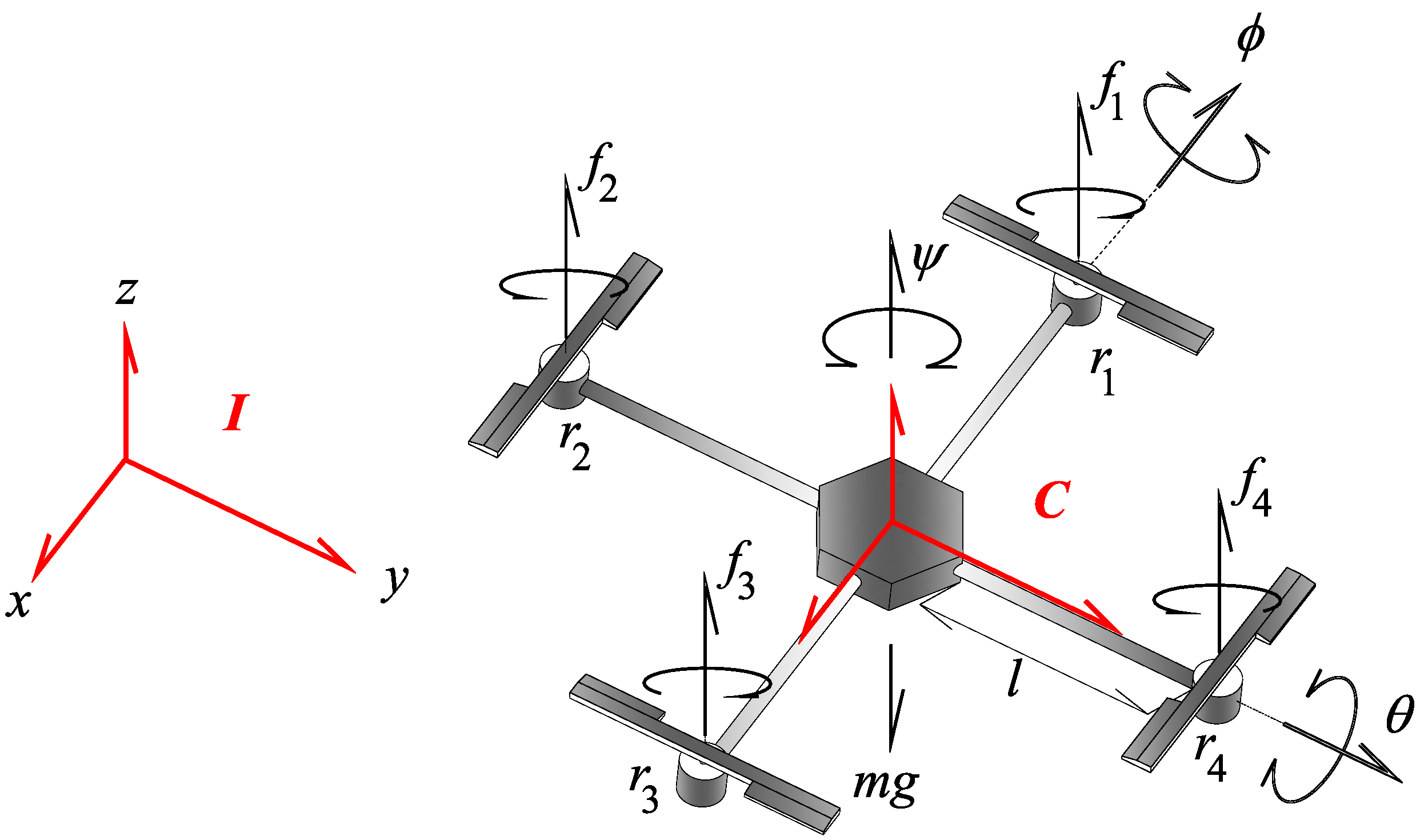
Figure 1. Kinematics and frames of reference of UAV quadrotor.
Fractalfract 08 00634 g001
Figure 2. A quadrotor’s possible movements: (a) pitch movement, (b) roll movement, (c) yaw movement, and (d) movement along the z axis (thrust).
Fractalfract 08 00634 g002
Figure 3. Classical order control system for quadrotor hovering.
Fractalfract 08 00634 g003
Figure 4. COCSH closed-loop response when the drone hovers at point P r e f 1 with an orientation of ψ = 0 radians.
Fractalfract 08 00634 g004
Figure 5. COCSH closed-loop response when the drone hovers at point P r e f 2 with an orientation of ψ = 0 radians.
Fractalfract 08 00634 g005
Figure 6. COCSH closed-loop response when the drone hovers at point P r e f 1 with an orientation of ψ = 0.4 radians.
Fractalfract 08 00634 g006
Figure 7. COCSH closed-loop response when the drone hovers at point P r e f 2 with an orientation of ψ = 0.4 radians.
Fractalfract 08 00634 g007
Figure 8. FOCSH closed-loop response when the drone hovers at point P r e f 1 with α = 0.99 and an orientation of ψ = 0 radians.
Fractalfract 08 00634 g008
Figure 9. FOCSH closed-loop response when the drone hovers at point P r e f 2 with α = 0.99 and an orientation of ψ = 0 radians.
Fractalfract 08 00634 g009
Figure 10. FOCSH closed-loop response when the drone hovers at point P r e f 1 with α = 1.098 and an orientation of ψ = 0.4 radians.
Fractalfract 08 00634 g010
Figure 11. FOCSH closed-loop response when the drone hovers at point P r e f 2 with α = 1.0044 and an orientation of ψ = 0.4 radians.
Fractalfract 08 00634 g011
Figure 12. COCSH and FOCSH (with α = 0.99 ) closed-loop response comparison when the drone hovers at point P r e f 1 with an orientation of ψ = 0 radians.
Fractalfract 08 00634 g012
Figure 13. COCSH and FOCSH (with α = 0.9882 ) closed-loop response comparison when the drone hovers at point P r e f 1 with an orientation of ψ = 0 radians.
Fractalfract 08 00634 g013
Figure 14. COCSH and FOCSH (with α = 0.99 ) closed-loop response comparison when the drone hovers at point P r e f 2 with an orientation of ψ = 0 radians.
Fractalfract 08 00634 g014
Figure 15. COCSH and FOCSH (with α = 0.9 ) closed-loop response comparison when the drone hovers at point P r e f 2 with an orientation of ψ = 0 radians.
Fractalfract 08 00634 g015
Figure 16. COCSH and FOCSH (with α = 1.098 ) closed-loop response comparison when the drone hovers at point P r e f 1 with an orientation of ψ = 0.4 radians.
Fractalfract 08 00634 g016
Figure 17. COCSH and FOCSH (with α = 1.388 ) closed-loop response comparison when the drone hovers at point P r e f 1 with an orientation of ψ = 0.5 radians.
Fractalfract 08 00634 g017
Figure 18. COCSH and FOCSH (with α = 1.0044 ) closed-loop response comparison when the drone hovers at point P r e f 2 with an orientation of ψ = 0.4 radians.
Fractalfract 08 00634 g018
Figure 19. COCSH and FOCSH (with α = 1.294 ) closed-loop response comparison when the drone hovers at point P r e f 2 with an orientation of ψ = 0.5 radians.
Fractalfract 08 00634 g019
Figure 20. COCSH MSE translational positions x, y, and z when the drone hovers at point P r e f 1 with an orientation of ψ = 0 radians.
Fractalfract 08 00634 g020
Figure 21. COCSH MSE translational positions x, y, and z when the drone hovers at point P r e f 2 with an orientation of ψ = 0 radians.
Fractalfract 08 00634 g021
Figure 22. COCSH MSE translational positions x, y, and z when the drone hovers at point P r e f 1 with an orientation of ψ = 0.4 radians.
Fractalfract 08 00634 g022
Figure 23. COCSH MSE translational positions x, y, and z when the drone hovers at point P r e f 1 with an orientation of ψ = 0.5 radians.
Fractalfract 08 00634 g023
Figure 24. COCSH MSE translational positions x, y, and z when the drone hovers at point P r e f 2 with an orientation of ψ = 0.4 radians.
Fractalfract 08 00634 g024
Figure 25. COCSH MSE translational positions x, y, and z when the drone hovers at point P r e f 2 with an orientation of ψ = 0.5 radians.
Fractalfract 08 00634 g025
Figure 26. FOCSH MSE translational positions x, y, and z when the drone hovers at point P r e f 1 with α = 0.99 and an orientation of ψ = 0 radians.
Fractalfract 08 00634 g026
Figure 27. FOCSH MSE translational positions x, y, and z when the drone hovers at point P r e f 1 with α = 0.9882 and an orientation of ψ = 0 radians.
Fractalfract 08 00634 g027
Figure 28. FOCSH MSE translational positions x, y, and z when the drone hovers at point P r e f 2 with α = 0.99 and an orientation of ψ = 0 radians.
Fractalfract 08 00634 g028
Figure 29. FOCSH MSE translational positions x, y, and z when the drone hovers at point P r e f 2 with α = 0.9 and an orientation of ψ = 0 radians.
Fractalfract 08 00634 g029
Figure 30. FOCSH MSE translational positions x, y, and z when the drone hovers at point P r e f 1 with α = 1.098 and an orientation of ψ = 0.4 radians.
Fractalfract 08 00634 g030
Figure 31. FOCSH MSE translational positions x, y, and z when the drone hovers at point P r e f 1 with α = 1.388 and an orientation of ψ = 0.5 radians.
Fractalfract 08 00634 g031
Figure 32. FOCSH MSE translational positions x, y, and z when the drone hovers at point P r e f 2 with α = 1.0044 and an orientation of ψ = 0.4 radians.
Fractalfract 08 00634 g032
Figure 33. FOCSH MSE translational positions x, y, and z when the drone hovers at point P r e f 2 with α = 1.294 and an orientation of ψ = 0.5 radians.
Fractalfract 08 00634 g033
Figure 34. COCSH and FOCSH closed-loop response comparison when the drone hovers at point P r e f 1 with an orientation of ψ = 0.5 radians and considering a simulation time of 300 s.
Fractalfract 08 00634 g034
Figure 35. COCSH and FOCSH closed-loop response comparison when the drone hovers at point P r e f 2 with an orientation of ψ = 0.5 radians and considering a simulation time of 300 s.
Fractalfract 08 00634 g035
Table 1. Definition of state-space variables.
State-Space VariablesState-Space Variables
x 1 = ϕ x 7 = x
x 2 = ϕ ˙ = x ˙ 1 x 8 = x ˙ = x ˙ 7
x 3 = θ x 9 = y
x 4 = θ ˙ = x ˙ 3 x 10 = y ˙ = x ˙ 9
x 5 = ψ x 11 = z
x 6 = ψ ˙ = x ˙ 5 x 12 = z ˙ = x ˙ 11
Table 2. UAV model parameters.
DescriptionParameter Value
UAV mass m = 1.4 kg
UAV rotor mass0.088 kg
UAV arm length l = 0.28 m
x axis inertia I x x = 0.0116 kgm 2
y axis inertia I y y = 0.0116 kgm 2
z axis inertia I z z = 0.0232 kgm 2
conversion constant f u to f τ ψ T q
Table 3. SMCO and SMFO performance indices and BQC-LR indicator. * denotes the best control system.
MSE Translational PositionBQC-LR
Hover at PointCOCSHFOCSHCOCSHFOCSH
with α = 0.99 :
P r e f 1 , ψ = 0 x = 22.9379 x = 22.8384
P r e f 1 , ψ = 0 y = 22.6470 y = 22.5594
P r e f 1 , ψ = 0 z = 11.4007 z = 11.4005
with α = 0.9882 :
P r e f 1 , ψ = 0 x = 22.9379 x = 22.8196 *
P r e f 1 , ψ = 0 y = 22.6470 y = 22.5433 *
P r e f 1 , ψ = 0 z = 11.4007 z = 11.4005 *
with α = 0.99 :
P r e f 2 , ψ = 0 x = 19.9253 x = 19.6805
P r e f 2 , ψ = 0 y = 19.7716 y = 19.5311
P r e f 2 , ψ = 0 z = 9.43305 z = 9.43283
with α = 0.9 :
P r e f 2 , ψ = 0 x = 19.9253 x = 17.6854 *
P r e f 2 , ψ = 0 y = 19.7716 y = 17.5683 *
P r e f 2 , ψ = 0 z = 9.43305 z = 9.43212 *
with α = 1.098 :
P r e f 1 , ψ = 0.4 x = 93.5583 x = 88.0133 *
P r e f 1 , ψ = 0.4 y = 68.8172 y = 63.5451 *
P r e f 1 , ψ = 0.4 z = 11.5617 z = 11.5523 *
with α = 1.388 :
P r e f 1 , ψ = 0.5 x = 409.737 x = 174.478 *
P r e f 1 , ψ = 0.5 y = 383.163 y = 164.591 *
P r e f 1 , ψ = 0.5 z = 11.7052 z = 11.6387 *
with α = 1.0044 :
P r e f 2 , ψ = 0.4 x = 88.0238 x = 87.5527 *
P r e f 2 , ψ = 0.4 y = 70.2942 y = 69.8361 *
P r e f 2 , ψ = 0.4 z = 9.55915 z = 9.55868 *
with α = 1.294 :
P r e f 2 , ψ = 0.5 x = 411.975 x = 251.481 *
P r e f 2 , ψ = 0.5 y = 384.125 y = 238.299 *
P r e f 2 , ψ = 0.5 z = 9.68843 z = 9.68571 *
Disclaimer/Publisher’s Note: The statements, opinions and data contained in all publications are solely those of the individual author(s) and contributor(s) and not of MDPI and/or the editor(s). MDPI and/or the editor(s) disclaim responsibility for any injury to people or property resulting from any ideas, methods, instructions or products referred to in the content.