Article

Fractal Numerical Investigation of Mixed Convective Prandtl-Eyring Nanofluid Flow with Space and Temperature-Dependent Heat Source

by
Yasir Nawaz
1,
Muhammad Shoaib Arif
2,3,*,
Muavia Mansoor
4,
Kamaleldin Abodayeh
2 and
Amani S. Baazeem
5
1
Comwave Institute of Sciences & Information Technology, F-8 Markaz, Islamabad 44000, Pakistan
2
Department of Mathematics and Sciences, College of Humanities and Sciences, Prince Sultan University, Riyadh 11586, Saudi Arabia
3
Department of Mathematics, Air University, PAF Complex E-9, Islamabad 44000, Pakistan
4
Department of Mathematics, Faculty of Basic Sciences, University of Wah, Wah Cantt 47040, Pakistan
5
Department of Mathematics and Statistics, College of Science, Imam Mohammad Ibn Saud Islamic University, P.O. BOX 90950, Riyadh 11623, Saudi Arabia
*
Author to whom correspondence should be addressed.
Fractal Fract. 2024, 8(5), 276; https://doi.org/10.3390/fractalfract8050276
Submission received: 15 February 2024 / Revised: 23 April 2024 / Accepted: 29 April 2024 / Published: 6 May 2024
(This article belongs to the Special Issue Heat Transfer and Diffusion Processes in Fractal Domains)

Abstract

:
An explicit computational scheme is proposed for solving fractal time-dependent partial differential equations (PDEs). The scheme is a three-stage scheme constructed using the fractal Taylor series. The fractal time order of the scheme is three. The scheme also ensures stability. The approach is utilized to model the time-varying boundary layer flow of a non-Newtonian fluid over both stationary and oscillating surfaces, taking into account the influence of heat generation that depends on both space and temperature. The continuity equation of the considered incompressible fluid is discretized by first-order backward difference formulas, whereas the dimensionless Navier–Stokes equation, energy, and equation for nanoparticle volume fraction are discretized by the proposed scheme in fractal time. The effect of different parameters involved in the velocity, temperature, and nanoparticle volume fraction are displayed graphically. The velocity profile rises as the parameter I grows. We primarily apply this computational approach to analyze a non-Newtonian fluid’s fractal time-dependent boundary layer flow over flat and oscillatory sheets. Considering spatial and temperature-dependent heat generation is a crucial factor that introduces additional complexity to the analysis. The continuity equation for the incompressible fluid is discretized using first-order backward difference formulas. On the other hand, the dimensionless Navier–Stokes equation, energy equation, and the equation governing nanoparticle volume fraction are discretized using the proposed fractal time-dependent scheme.

1. Introduction

Nanofluids are potential candidates for heat transfer and flow and have been studied profoundly in recent years. Nanofluids are applied in various industries, e.g., in cooling systems, energy storage, and catalysis. Nanofluids are fluids containing nanoparticles ranging from 1 to 100 nm, so they are engineered fluids. This is a mixture of nanoparticles of a specific size tuning with a base fluid.
Nanoparticles also enhance some properties of the fluid (effective property), such as the thermal conductivity of the fluid. The Prandtl-Eyring model is one of the most used models for modelling the flow of these nanofluids.
The nanoparticle in the nanofluid acts somewhat like a gas. The behavior of the nanoparticles is considered in this model. The Prandtl-Eyring model is used to model the flow of the nanofluids and predict their heat transfer performance in various situations, geometries, or configurations.
The Prandtl-Eyring model considers the phenomenon of slipping among the fluid and nanoparticles. But it is not without limitations; first, the fluid-time thermal conductivity is considered constant. Secondly, the behavior and the effects of the size and shape of the nanoparticles on the properties of the fluid are not taken into account. Thus, to overcome these limitations and assumptions, the generalization of the Prandtl-Eyring model can give rise to as many new models, such as the tempered fractional Prandtl-Eyring model, tempered Prandtl-Eyring model, or fractal Prandtl-Eyring model.
When an aircraft wing or a pipe has a liquid layer in contact with its surface, and when the liquid sheet is thin, the limit of fluid mechanics comes into action. The liquid can separate if the shear force affects it in the boundary layer.
This work aims to improve the complex interplay between many components that govern nanoscale fluid flow, heat transmission, and particle dispersion. The primary objective of this undertaking is to gain a comprehensive understanding of and improve the complex interplay among several factors that influence fluid dynamics, heat transmission, and particle dispersion at the nanoscale. When the fluid stays in contact with the surface, the individual layer speeds up the fluid from the optimum limit to zero at the boundary layer. For example, the limits on the trailing edge of the airplane wing are tiny and denser. Along the front or at the upstream of these, the boundaries of the limits thicken. The concept of boundary layers was suggested by Prandtl in 1904 to explain the flow behavior of the viscous fluid near a resolved barrier [1]. Using the finite Reynolds number flow, Prandtl made and deduced the boundary layer equations by using the Navier Stoke equations. As requested, the boundary layer theory equations are the compulsory and necessary simplification of the original Navier–Stokes derivative.
To develop equations on this phenomenon, the vast region over and around the boundary layer and a smaller area where the boundary layer flows are studied closely and built. Various product-specific boundary conditions about the physical model are used to solve the boundary layer equations.
The heat transport in the thermal boundary layer can be reduced by using magnetic and Peclet numbers in the case of magnetohydrodynamic (MHD) flow of fluid with gyrotactic microorganisms [2]. The magnified thermal boundary layer thickness is noticed when a shrunken fluid flows to the growing porous wedge of the Casson liquid as the convective heat transfers [3]. A few other experiments include the influences of various physical parameters on the boundary layer flow [4,5,6].
Many systems use nanofluids, defined as nanomaterials dispersed in a pure fluid, because of their improved specification [7]. Nanofluids have an impressive advantage over more traditional fluids in terms of enhanced thermal conductivity [8]. The interaction between nanoparticles and base fluid, as well as other factors, dramatically affects the viscosity of nanofluids [9]. Although the non-Newtonian behavior of nanofluids has been widely documented, different authors have noted that they behave like Newtonian fluids [10]. Coating wire and blades, processing molten plastic, dyeing textiles, moving biological fluids, processing foods and slurries, and certain petroleum fluids are all examples of practical applications of non-Newtonian behaviors. Power law, micropolar, Reiner-Philippoff, viscoelastic, Casson, Carreau, Giesekus, Prandtl, Prandtl-Eyring, and Powell-Eyring models are among those that can be anticipated in this respect [11]. To achieve the required behavior, these models prioritize the momentum conservation equations to a greater extent. Each model provides a mathematical representation of the relationship between shear stress and deformation rate. The function of sine hyperbolic is Prandtl, while Prandtl-Eyring is a sine inverse function [12,13]. The power law model describes the relationship as nonlinear [14]. A micropolar Prandtl fluid in a porous stretched sheet scenario was investigated by Sajid et al. [15]. We assumed a chemical reaction was occurring in the medium and that the heat source was temperature-dependent. A numerical investigation of power law nanofluid flow on a porous plate was carried out by Maleki et al. [16]. Despite their expectations, they found that using Newtonian nanofluid did not enhance heat transmission.
On the other hand, increasing heat transport was a crucial function of the non-Newtonian one. The phenomenon of Prandtl-Eyring fluid movement through a sensor surface under conditions of magnetic force was studied by Shankar and Naduvinamani [17]. An increase in the velocity field and a decrease in the temperature profile were seen as a result of adding magnetic parameters. Heat transport decreased as the Prandtl number increased simultaneously. Al-Kaabi and Al-Khafajy [18] studied the effects of temperature and concentration changes on the Prandtl-Eyring fluid heat transfer in a porous medium. The experiment was performed by Hayat et al. [19]. According to them, Prandtl-Eyring liquid has been subjected to an extending piece with gyratory microorganisms. It has been proved that by increasing the melting parameters, the velocity increases and decreases the temperature.
Therefore, extending a surface is a well-known and common exercise in many industries, such as extrusion, cooling metallic plates, glass-blown products, ceramics production, rubbers pouring in fiberglass, and many more. One theory that sheds light on the underlying scientific facts is boundary layer flow and heat transfer [20]. Practical difficulties encountered in engineering applications often involve nonlinear equations. Using the Keller-box method [21] can cure such problems. The Prandtl-Eyring liquid flow on a strained sheet was prescribed by Munjam et al. [22]. Munjam et al. [22] also discovered a new method to solve these problems. They then separated their findings from those of the Keller-box system. Their results showed that the velocity also rises with increased liquid parameters. The analysis showed that the velocity increases with a rise in the fluid parameter. They also discovered that, in contrast to the viscous fluid, the Prandtl-Eyring fluid causes a higher gross velocity value.
In their study on the entropy generation of Casson nanofluid, Jamshed et al. [23] utilized the Tiwari and Das model in conjunction with the Keller box approach to solving ordinary differential equations. After incorporating C u and T i O 2 nanoparticles into two different methanol-based nanofluids, the performance of the C u nanofluids was shown to be superior. Similar concepts and methods were employed in [24] for the base fluid of engine oils and nanoparticles. Their research led them to conclude that increasing the Reynolds and Brinkman numbers would improve entropy generation. Shear rate enhancement was also observed as the concentration of nanofluids increased. Abdelmalek et al. [25] have stated that a Prandtl-Eyring nanofluid can impact Brownian motion and thermophoretic force on a stretched surface. The negative effect of magnetic force on momentum has been demonstrated. On the other hand, the thermal energy was increased via thermophoretic force and Brownian motion.
The growth of various industries, especially in terms of thermal properties, has generated interest in many forms of nanofluid. The applications of nanofluid flow in different sectors are as follows:
  • Cooling systems: Nanofluids have demonstrated potential in improving the thermal efficiency of cooling systems, specifically in electronic devices and microchips. Efforts are currently being made to commercialize nanofluids in order to enhance heat removal efficiency in these applications.
  • Energy storage: It is worth noting that nanofluids have the potential to enhance the thermal efficiency of energy storage systems, including fuel cells. Efforts are being made to utilize the improved thermal conductivity of nanofluids to optimize energy storage and conversion processes.
  • Catalysis: The unique features of nanofluids make them highly promising for catalytic applications, where they can significantly improve reaction speeds and selectivity. Pharmaceutical, chemical synthesis, and environmental remediation are some of the potential applications of nanofluids that are the focus of current research.
  • Heat exchangers. Because of their exceptional thermal qualities, nanofluids are finding more and more uses as coolants in heat exchangers, where they greatly enhance performance and efficiency. Improvements in the preparation and use of nanofluids for different heat exchange purposes are the subject of continuing research.
  • Vehicle thermal management: Vehicles, such as hybrid electric vehicles and chilled engines, can potentially benefit from nanofluids for heat management. Improving vehicle cooling and thermal management systems is the focus of research efforts. Nanofluids are being considered as potential solutions.
In general, nanofluids are seen as the next big thing in heat transfer fluids since they outperform conventional fluids in terms of thermal conductivity and convective heat transfer coefficient.
The use of spatial fractional derivatives in Fourier’s law modelling has recently been explored in several field studies to improve the precision of physical problem simulations [26,27]. When trying to simulate the behavior of nanofluids, the first-order derivative of the temperature, which is a part of classical Fourier’s law that describes the process of heat conduction, is insufficiently precise. According to recent studies, nanofluid flow modelling can be more accurate using Fourier’s law with spatial-fractional derivatives [28,29]. A fractional order gradient, expressed as the Fourier’s law heat flux relative to the nanofluid, is computed in his model using q λ T ( X , Y ) where λ is a non-integer order.
Caputo and the Riemann-Liouville (R-L) derivatives are popular fractional derivatives [30,31]. Asjad et al. recently applied time-fractional derivatives to nanofluid convection flow between parallel plates [32] and maxwell fluid heat transfer over a vertical surface [33,34,35]. The boundary conditions impact the outcomes more than the initial conditions due to the nonlinear nature of the space derivative terms (e.g., momentum and energy) in the transport equations. Recent research on boundary layer problems has explored fractional derivatives from various angles, as shown in Table 1.
By adding two additional variables to the original equation, which converts it into a system of low-order equations, a completely discrete difference scheme is obtained [43] for a diffusion-wave system. Their innovative approach to tackling time-fractional initial-boundary value problems is detailed in [44]. These problems involve summing Caputo derivatives with orders ranging from 0 to 1. A new linearized transformed L 1 Galerkin finite element approach is presented for numerical solutions of the multi-dimensional time fractional Schrödinger equations [45]. The fully discrete scheme’s conditionally optimum error estimates are demonstrated. In reference [46], the fractional boundary conditions multi-term time-space diffusion equation is examined. The standard and shifted Grundwald Letnikov formula is used to approximate the fractional derivative in space, whereas the L 2 1 σ formula is used to estimate the fractional derivative in time.
We have proposed an efficient three-stage scheme for the time fractal Prandtl-Eyring nanofluid flow with space and temperature-dependent heat sources. The Prandtl-Eyring model is limited in its ability to account for the influence of nanoparticle temperature, shape, and size on the characteristics of the fluid. Utilizing computational techniques, significant insights into the system were derived from investigations into the complex dynamics of a non-Newtonian fluid’s fractal time-dependent boundary layer flow over both flat and oscillatory sheets. By discretizing important equations controlling fluid behavior, such as the continuity equation, the dimensionless Navier–Stokes equation, and the energy and nanoparticle volume fraction equations, the proposed scheme demonstrates its flexibility and resilience in dealing with complex fluid mechanics situations.
Reasons for choosing the method: A fractal Runge–Kutta scheme is proposed. The scheme is explicit and provides the third accurate solution in fractal time. The technique can also be used to find the solutions of classical partial differential equations. It is among the most efficient numerical schemes among other third-order schemes. It does not require linearization, so it can find solutions to nonlinear differential equations without using any other iterative method. Since there is not much work on fractal numerical schemes in the literature, a fractal scheme is proposed. However, the scheme can be used only with time fractal derivatives, in which a classical rise in the dependent variable is used, and fractal variation is considered with the run. So, the considered fractal derivative is just a classical or standard rise over a fractal run.
Pros and cons of the method: The pros and cons can be seen from the constructed Table 2 comparisons of the three schemes. The proposed scheme produces less error than the other two but has a low numerical convergence order. Still, theoretically, it gives a solution of third-order accuracy, whereas the other two methods give the solution of first and second-order accuracy. Nevertheless, the approach may provide difficulties concerning its implementation, substantial computing expenses, restricted validation using empirical data, and susceptibility to parameter selections.
Here is a concise summary of the paper. Two definitions are offered, followed by the proposal of a fractal scheme. The subsequent section presents an analysis of the stability of the scheme for a scalar fractal time partial differential equation, as well as an examination of convergence for a system of time fractal convection diffusion issues. The scheme is also utilized in a fluid dynamics problem, where the results are analyzed and shown in various graphs. Additionally, a comparison of the scheme is conducted.
Definition 1 
([47]). The fractal derivative of a function  g t  with respect to fractal measure,  t  is defined as
f t α = l i m t 1 t g t 1 g t t 1 α t α ,   α > 0 .
Definition 2 
([48]). The fractal Taylor series expansion for the function g t is given as
g t = m = 0 D α m g t m ! ,
where D α m , m t h order fractal derivative of g ( t ) and 0 < α < 1 .

2. Proposed Fractal Numerical Scheme

This work proposes a fractal computational scheme to solve fractal partial differential equations. The scheme is a three-stage scheme that utilizes the two predictors and one corrector stage. It only discretized the time-dependent terms in a given fractal partial differential equation. This scheme divides the whole-time length into different time levels. It is noted that equal time stepping is used for each stage. However, time steps can be different in all three stages, i.e., stage one utilizes a one-time step, stage two uses another time step, and the third stage employs a time step different from the first two time steps. To apply the scheme, consider the fractal partial differential equation of the following form:
v t α = G v , v x ,   v y , 2 v y 2 ,
where 0 < α 1 . Subject to initial and boundary conditions given as follows:
v x , y , 0 = 0 v 0 , y , t = β 1   v x , 0 , t = β 2 v x , L , t = β 3   ,
where β i   i = 1,2 , 3 are constant.
The first stage of the proposed scheme is described as follows:
v ¯ i , j n + 1 = v i , j n + Δ t 1 v t α i , j n ,
where Δ t 1 = 1 3 ( t n + 1 α t n α ) is a time step.
The second stage of the scheme is given as follows:
v ̿ i , j n + 1 = 1 3 2 v i , j n + v ¯ i , j n + 1 + Δ t 2 v ¯ t α i , j n + 1 = v i , j n + 1 3 Δ t 1 + Δ t 2 v t α i , j n + Δ t 1 Δ t 2 t α 2 v i , j n
Stages (3) and (4) are predictor stages. The corrector stage can be expressed as follows:
v i , j n + 1 = a v i , j n + b v ¯ i , j n + 1 + c v ̿ i , j n + 1 + d Δ t v ̿ t α i , j n + 1 ,
where a , b , c , and d are parameters to be determined later.
By using the first and second stages (3) and (4) in the third stage (5), it results in the following:
v i , j n + 1 = a v i , j n + b v i , j n + b Δ t 1 v t α i , j n + c v i , j n + c 1 3 Δ t 1 + Δ t 2 v t α i , j n + c Δ t 1 Δ t 2 v t α 2 v i , j n + d Δ t v t α i , j n + 1 3 Δ t 1 + Δ t 2 t α 2 v i , j n + Δ t 1 Δ t 2 t α 3 v i , j n ,
Consider the fractal Taylor series expansion v i , j n + 1 as follows:
v i , j n + 1 = v i , j n + Δ t t α v i , j n + Δ t 2 2 t α 2 v i , j n + Δ t 3 6 t α 3 v i , j n +
Substituting fractal Taylor series expansion (7) into Equation (6) results in the following:
v i , j n + Δ t v t α i , j n + Δ t 2 2 t α 2 v i , j n + Δ t 3 6 t α 3 v i , j n + O Δ t 4 = a v i , j n + b v i , j n + b Δ t 1 v t α i , j n + c v i , j n + c 1 3 Δ t 1 + Δ t 2 v t α i , j n + c Δ t 1 Δ t 2 t α 2 v i , j n + d Δ t v t α i , j n + 1 3 Δ t 1 + Δ t 2 t α 2 v i , j n + Δ t 1 Δ t 2 t α 3 v i , j n ,
By equating coefficients of v i , j n , v t α i , j n , t α 2 v i , j n and t α 3 v i , j n on both sides of Equation (8) it yields the following:
a + b + c = 1 b Δ t 1 + c 3   Δ t 1 + c Δ t 2 + d Δ t = Δ t c Δ t 1 Δ t 2 + d 3 Δ t Δ t 1 + d Δ t Δ t 2 = Δ t 2 2 d Δ t Δ t 1 Δ t 2 = Δ t 3 6 ,
By solving the system of Equation (9), the values of unknown can be written as follows:
a = 2 Δ t 3 Δ t 1 2 12 Δ t 3 Δ t 1 Δ t 2 + 18 Δ t 2 Δ t 1 2 Δ t 2 + 9 Δ t 3 Δ t 2 2 27 Δ t 2 Δ t 1 Δ t 2 3 + 54 Δ t Δ t 1 2 Δ t 2 2 54 Δ t 1 3 Δ t 2 2 54 Δ t 1 3 Δ t 2 2 , b = Δ t 3 Δ t 1 2 + 3 Δ t 3 Δ t 1 Δ t 2 + 9 Δ t 2 Δ t 1 2 Δ t 2 9 Δ t 3 Δ t 2 2 + 27 Δ t 2 Δ t 1 Δ t 2 2 54 Δ t Δ t 1 2 Δ t 2 2 54 Δ t 1 3 Δ t 2 2 , c = Δ t 3 Δ t 1 + 32 Δ t 3 Δ t 2 9 Δ t 2 Δ t 1 Δ t 2 18 Δ t 1 2 Δ t 2 2 , d = Δ t 2 6 Δ t 1 Δ t 2 .
Therefore, the proposed scheme for fractal discretization of Equation (1) with G = α 1 v x + α 2 v y + α 3 2 v y 2 and second-order space discretization is written as follows:
v ¯ i , j n + 1 = v i , j n + Δ t 1 α 1 δ x v i , j n + α 2 δ y v i , j n + α 3 δ y 2 v i , j n .
v ̿ i , j n + 1 = 1 3 2 v i , j n + v ¯ i , j n + 1 + Δ t 2 α 1 δ x v ¯ i , j n + 1 + α 2 δ y δ x v ¯ i , j n + 1 + α 3 δ y 2 v ¯ i , j n + 1 .
v i , j n + 1 = a v i , j n + b v ¯ i , j n + 1 + c v ̿ i , j n + 1 + d Δ t α 1 δ x v ̿ i , j n + 1 + α 2 δ y v ̿ i , j n + 1 + α 3 δ y 2 v ̿ i , j n + 1 .
where δ x v i , j n = v i + 1 , j n v i 1 , j n 2 Δ x , δ y v i , j n = v i , j + 1 n v i , j 1 n 2 Δ y , δ y 2 v i , j n = v i , j + 1 n 2 v i , j n + v i , j 1 n Δ y 2 .

3. Stability Analysis

The Fourier series analysis can be used for finite difference methods to find the stability conditions of linear differential equations. The technique transforms the difference equation into trigonometric equations. The analysis is utilized for linear partial differential equations, while it determines the precise stability criteria for nonlinear partial differential equations. Because for nonlinear partial differential equations, it is used to linearize PDEs. To apply this analysis, consider the following transformations:
v i , j n = E n e i J ψ 1 e j I ψ 2 v ¯ i , j n + 1 = E ¯ n + 1 e i I ψ 1 e j I ψ 2 v ̿ i , j n + 1 = E ̿ n + 1 e i I ψ 1 e j I ψ 2 ,
where I = 1 and ψ 1 = p ¯ x and ψ 2 = q ¯ y are two-phase angles and p ¯ and q ¯ are two wave numbers, respectively, in x and y directions, i.e. ,   λ x = 2 π p ¯ and λ y = 2 π q ¯ are wavelengths, and E n is the amplitude at time level n . By substituting the relevant transformations from Equation (14) into the first step of the proposed scheme Equation (11), it produces a result.
E ¯ n + 1 e i I ψ 1 e j I ψ 2 = E n e i I ψ 1 e j I ψ 2 + Δ t 1 { α 1 e i + 1 I ψ 1 e j I ψ 2 e i 1 I ψ 1 e j I ψ 2 2 Δ x E n + α 2 e i I ψ 1 e j + 1 I ψ 2 e i I ψ 1 e j 1 I ψ 2 2 Δ y E n + α 3 e i I ψ 1 e ( j + 1 ) I ψ 2 2 e i I ψ 1 e j I ψ 2 + e i I ψ 1 e j 1 I ψ 2 Δ y 2 E n } ,
Simplifying Equation (15) yields
E ¯ n + 1 = E n + Δ t 1 α 1 e I ψ 1 e I ψ 1 2 Δ x E n + α 2 e I ψ 2 e I ψ 2 2 Δ y E n + α 3 e I ψ 2 2 + e I ψ 2 Δ y 2 E n
E ¯ n + 1 = E n + Δ t 1 α 1 I s i n ψ 1 Δ x + α 2 I s i n ψ 2 Δ y + α 3 ( 2 c o s ψ 2 2 ) Δ y 2   E n .
Let c ¯ 1 = α 1 Δ t 1 Δ x , c ¯ 2 = α 2 Δ t 1 Δ y , d ¯ 1 = 2 α 3 Δ t 1 Δ y 2 , then Equation (16) can be written as follows:
E ¯ n + 1 = E n + c ¯ 1 I s i n ψ 1 + c ¯ 2 I s i n ψ 2 + d ¯ 1 ( c o s ψ 2 1 ) E n .
Similarly, the second stage can be transformed as follows:
E ¯ ¯ n + 1 = 1 3 2 E n + E ¯ n + 1 + c ^ 1 I s i n ψ 1 + c ^ 2 I s i n ψ 2 + d ^ 1 ( c o s ψ 2 1 ) E ¯ n + 1 = 2 3 E n + 1 3 + c ^ 1 I s i n ψ 1 + c ^ 2 I s i n ψ 2 + d ^ 1 c o s ψ 2 1 E ¯ n + 1 = 2 3 E n + 1 3 + c ^ 1 I s i n ψ 1 + c ^ 2 I s i n ψ 2 + d ^ 1 c o s ψ 2 1 ( 1 + c ¯ 1 I s i n ψ 1 + c ¯ 2 I s i n ψ 2 + d ¯ 1 ( c o s ψ 2 1 ) ) E n .
where c ^ 1 = α 1 Δ t 2 Δ x , c ^ 2 = α 2 Δ t 2 Δ y , d ^ 1 = 2 α 3 Δ t 2 Δ y 2 .
The third stage of the scheme can be expressed as follows:
E n + 1 = a E n + b 1 + c ¯ 1 I s i n ψ 1 + c ¯ 2 I s i n ψ 2 + d ¯ 1 c o s ψ 2 1 E n + c + c 1 I s i n ψ 1 + c 2 I s i n ψ 2 + d 1 c o s ψ 2 1 { 2 3 + 1 3 + c ^ 1 I s i n ψ 1 + c ^ 2 I s i n ψ 2 + d ^ 1 c o s ψ 2 1 ( 1 + c ¯ 1 I s i n ψ 1 + c ¯ 2 I s i n ψ 2 + 2 d ¯ 1 c o s ψ 2 1 ) } E n ,
The amplification factor, in this case, is
E n + 1 E n 2 = | a + b 1 + c ¯ 1 I s i n ψ 1 + c ¯ 2 I s i n ψ 2 + d ¯ 1 c o s ψ 2 1 + c + c 1 I s i n ψ 1 + c 2 I s i n ψ 2 + d 1 c o s ψ 2 1 { 2 3 + 1 3 + c ^ 1 I s i n ψ 1 + c ^ 2 I s i n ψ 2 + d ^ 1 c o s ψ 2 1 ( 1 + c ¯ 1 I s i n ψ 1 + c ¯ 2 I s i n ψ 2 + 2 d ¯ 1 c o s ψ 2 1 ) } | 2 < 1 .
Therefore, the scheme will be stable if it satisfies the conditions (20).
The stability of the suggested scheme for scalar partial differential equations has been demonstrated. Now, we will provide the convergence of the method for the system of partial differential equations. To do so, consider the following vector matrix equation:
g t α = A 1 g x + B 1 g y + C 1 2 g y 2 + D 1 g .
By applying a proposed scheme on Equation (20), it gives the following:
g ¯ i , j n + 1 = g i , j n + Δ t 1 A 1 δ x g i , j n + B 1 δ y g i , j n + C _ 1 δ y 2 g i , j n + D 1 g i , j n .
g ̿ i , j n + 1 = 1 3 2 g i , j n + g ¯ i , j n + 1 + Δ t 2 A 1 δ x g ¯ i , j n + 1 + B 1 δ y g ¯ i , j n + 1 + C 1 δ y 2 g ¯ i , j n + 1 + D 1 g ¯ i , j n + 1 .
g i , j n + 1 = a g i , j n + b g ¯ i , j n + 1 + c g ̿ i , j n + 1 + Δ t A 1 δ x g ̿ i , j n + 1 + B 1 δ y g ̿ i , j n + 1 + C 1 δ y 2 g ̿ i , j n + 1 + D 1 g ̿ i , j n + 1 .
Theorem 1.
The proposed scheme (22)–(24) converges for Equation (21).
Proof. 
To prove this theorem, consider the first stage of the exact scheme.
G ¯ i , j n + 1 = G i , j n + Δ t 1 A 1 δ x G i , j n + B 1 δ y G i , j n + C 1 δ y 2 G i , j n + D 1 G i , j n ,
Subtracting Equation (22) from Equation (25), the following is obtained:
e ¯ i , j n + 1 = e i , j n + Δ t 1 A 1 δ x e i , j n + B 1 δ y e i , j n + C 1 δ y 2 e i , j n + D 1   e i , j n ,
where e ¯ i , j n + 1 = G ¯ i , j n + 1 g ¯ i , j n + 1 , e i , j n = G i , j n g i , j n , etc.
Taking the norm on both sides of Equation (25) gives
e ¯ i , j n + 1 e i , j n + Δ t 1 A 1 e i , j n Δ x + B 1 e i , j n Δ y + C 1 4 e i , j n Δ y 2 + D 1   e i , j n .
Re-write inequality (27) as
e ¯ n + 1 e n + P ¯ 1 + P ¯ 2 + P ¯ 3 + P ¯ 4 e n
where P ¯ 1 = A 1 Δ t 1 Δ x , P ¯ 2 = B 1 Δ t 1 Δ y , P ¯ 3 = 4 C 1 Δ y 2 and, P ¯ 4 = D 1 .
Similarly, for the second stage, the following inequality can be obtained.
e ̿ n + 1 1 3 2 e n + e ¯ n + 1 + P ^ 1 + P ^ 2 + P ^ 3 + P ^ 4 e ¯ n + 1 2 3 + 1 3 + P ^ 1 + P ^ 2 + P ^ 3 + P ^ 4 1 + P ¯ 1 + P ¯ 2 + P ¯ 3 + P ¯ 4 e n .
where P ^ 1 = Δ t 2 A 1 Δ x , P ^ 2 = Δ t 2 B 1 Δ y , P ^ 3 = Δ t 2 C 1 Δ y 2 , P ^ 4 = Δ t 2 D 1 .
Similarly, the following inequality can be obtained by subtracting the third stage of the scheme.
e n + 1 a e n + b e ¯ n + 1 + c e ̿ n + 1 + d P 1 + P 2 + P 3 + P 4 e ̿ n + 1 + N O Δ t 3 , Δ x 2 , Δ y 2
By using inequalities (28) and (29) into inequality (30), which yields
e n + 1 a e n + b 1 + P ¯ 1 + P ¯ 2 + P ¯ 3 + P ¯ 4 e n + c + d P 1 + P 2 + P 3 + P 4 { 2 3 + 1 3 + P ^ 1 + P ^ 2 + P ^ 3 + P ^ 4 1 + P ¯ 1 + P ¯ 2 + P ¯ 3 + P ¯ 4 } e n + N O Δ t 3 , Δ x 2 , Δ y 2 ,
Re-write inequality (31) as
e n + 1 μ e n + O Δ t 3 , Δ x 2 , Δ y 2 ,
Let n = 0 in inequality (32). It gives
e 1 N O Δ t 3 , Δ x 2 , Δ y 2 ,
Let n = 1 in inequality (32), it gives
e 2 μ e 1 + N O Δ t 3 , Δ x 2 , Δ y 2 1 + μ N O Δ t 3 , Δ x 2 , Δ y 2 ,
If this is continued, then for finite n
e n μ n 1 + + μ + 1 N O Δ t 3 , Δ x 2 , Δ y 2 = 1 1 μ n 1 μ N O Δ t 3 , Δ x 2 , Δ y 2 .
By applying the l i m i t   n in (35), the series 1 + μ + + μ n + becomes an infinite geometric series that will converge if μ < 1 . □

4. Problem Formulation

Examine the flow of a non-Newtonian fluid over a two-dimensional moving sheet, where the fluid is incompressible, unstable, and laminar. The movement of the sheet generates the flow in the fluid. Let the sheet move with the velocity u w . The x * -axis is placed along the sheet, whereas y * -axis is perpendicular to x * -axis. The fluid is moving from left to right along x * -axis. Temperature and concentration on the sheet are considered higher than ambient temperature and concentration. The governing equations can be written as follows:
u * x * + v * y * = 0 ,
u * t * + u * u * x * + v * u * y * = ν Λ w C ¯ 1 2 u * y * 2 + ν Λ w 2 C ¯ 1 3 u * y * 2 2 u * y * 2 σ B 2 ρ + g β T T T + β C C C ,
T t * + u * T x * + v * T y * = α 2 T y * 2 + τ D B Δ C T y * C y * + D T T T y * 2 + 1 ρ c p q ,
C t * + u * C x * + v * C y * = D B 2 C y * 2 + Δ C T D T 2 T y * 2 + D B T m k T 2 T y * 2 k r C C .
Subject to the initial and boundary conditions
u * = 0 ,   v * = 0 ,   T = 0 ,   C = 0   w h e n   t * = 0 u * = u w ,   v * = 0 , T = T w , C = C w   w h e n   y * = 0 u * = 0 = v * = T = C   w h e n   x * = 0 u * 0 , T T , C C   w h e n   y * ,
where q = k u w x ν ρ c p A * u T w T + B * T T is space- and temperature-dependent internal heat generation. Where Λ w and C ¯ 1 are material constants, g is gravity, β T represents coefficients of thermal expansion, β C represents coefficients of solutal expansion, σ is electric conductivity, B is the strength of the magnetic field, D B represents Brownian motion coefficients, D T is thermophoresis diffusion, Δ C is nanoparticle fraction difference, T m represents mean fluid temperature, k T denotes thermal diffusion ratio and k r is dimensional reaction rate.
By using transformations
x = x * L , y = y * L , t = u w t * L ,   u = u * u w θ = T T T w T ,   ϕ = C C C w C ,
Incorporating transformations (41) into (36)–(40) that yields
u x + v y = 0 ,
u t + u u x + v u y = ϵ 1 R e 2 u y 2 + ϵ 1 ϵ 2 u y 2 2 u y 2 H 2 R e u + G γ T R e 2 θ + G γ C R e 2 ϕ ,
θ t + u θ x + v θ y = 1 P r 1 R e 2 u y 2 + N b R e θ y ϕ y + N t R e θ y 2 + ϵ x 1 P r A * u + B * θ ,
ϕ t + u ϕ x + v ϕ y = 1 S c 1 R e 2 ϕ y 2 + N t N b 1 S c R e 2 θ y 2 + S r R e 2 θ y 2 γ ϕ .
Subject to the dimensionless initial and boundary conditions
u = 0 , v = 0 , θ = 0 = ϕ ,   w h e n   t = 0 u = 1 , v = 0 , θ = 1 = ϕ , w h e n   y = 0 u = 0 = v ,   θ = 0 = ϕ   w h e n   x = 0 u 0 ,   θ 0 , ϕ 0   w h e n   y ,
where ϵ 1 represents the parameter I, the dimensionless ratio of material constants indicated as ϵ 1 , is represented by parameter I. The stability and behavior of the fluid flow are significantly influenced by its role. This parameter plays a crucial role in determining the flow characteristics by influencing the strength of fluid motion concerning its viscosity. ϵ 2 denotes Prandtl-Eyring parameter II, the Prandtl-Eyring parameter, abbreviated as ϵ 2 , is a parameter that represents the dimensionless ratio of the product of the sheet velocity u w , viscosity ν , and characteristic length. The measurement assesses the impact of non-Newtonian phenomena on fluid flow dynamics. The degree of shear-thinning or shear-thickening behavior displayed by the fluid is influenced by Parameter II, which has important consequences for the evolution of the boundary layer and heat transfer. G γ T is the thermal Grashof number, G γ C is solutal Grashof number, H Hartmann number, ϵ is the dimensionless parameter, R e is the Reynolds number, N t represents the thermophoresis parameter, N b is Brownian motion coefficients, S r is Soret number, P r is Prandtl number, S c is the Schmidt number, and γ is the dimensionless parameter, and these are defined as
ε 1 = Λ w C ¯ 1 ,   ε 2 = u w ν 2 C ¯ 1 2 L 3 ,   G γ T = L 3 g β T T w T ν 2 ,   G γ C = L 3 g β C C w C ν 2 ,   H = B L σ ρ ν ,   R e = L u w ν , N t = τ D T T w T ν T ,   N b = τ D B C w C ν Δ C ,   S r = k T D B T w T ν T m C w C ,   P r = ν α ,   S C = ν D B , γ = L k r u w
The skin friction coefficients, local Nusselt number, and local Sherwood number are precisely defined as follows:
C f = τ w ρ u w 2 ,
N u L = L q w k T w T ,
S h C = L q j D B   C w C .
where τ w = μ Λ w C ¯ 1 u * y * μ Λ w 6 C ¯ 1 3 u * y * 3 y * = 0 , q w = k T y * y * = 0 , q j = D B C y * y * = 0 .
By using transformation (41) into (47)–(49), it gives
C f = ε 1 R e u y 1 3 ε 1 ε 2 u y 3 y = 0 ,
N u L = θ y y = 0 ,
S h L = ϕ y y = 0 ,
Since fractal derivatives are more generalized than classical ones, they rise over fractal runs. So, it finds the change of the dependent variable over the fractal measure. The time fractal derivative uses only the change of quantities using the fractal shift in time. Physically, fractal change can be considered an irregular interval of time. From a derivation point of view, Navier–Stokes equations can be generalized using fractal derivatives. The proposed scheme can be used for classical and time fractal partial differential equations. The time fractal model is
u x + v y = 0 ,
u t α + u u x + v u y = ε 1 R e 2 u y 2 + ε 1 ε 2 u y 2 2 u y 2 H 2 R e u + G γ T R e 2 θ + G γ C R e 2 ϕ ,
θ t α + u θ x + v θ y = 1 P r 1 R e 2 u y 2 + N b R e θ y ϕ y + N t R e θ y 2 + ε x 1 P r A * u + B * θ ,
ϕ t α + u ϕ x + v ϕ y = 1 S c 1 R e 2 ϕ y 2 + N t N b 1 S c R e 2 θ y 2 + S r R e 2 θ y 2 γ ϕ .
Subject to the same boundary conditions of the classical model.
Justification for Time Fractal Model: The incorporation of the time fractal model (Equations (54)–(56)) in our study is driven by the need to investigate the possible advantages of fractal derivatives in capturing complex temporal patterns in the flow of non-Newtonian fluids across a plate. The parameter α in the time fractional derivatives signifies the fractal time order, which indicates the irregular nature of the temporal progression of fluid dynamics. Fractal derivatives in time provide a more detailed explanation of time-dependent events, encompassing long-term memory effects and non-local dependencies that classical time derivatives may not fully encompass.
Physical meaning of α : The significance of α lies in its impact on the temporal progression of the system. A value of α ranging from 0 to 1 suggests subdiffusion, but α > 1 denotes superdiffusion. The choice of α is contingent upon the particular attributes of the fluid flow and the intended degree of temporal complexity in the model. By incorporating fractal time derivatives, our objective is to investigate if this method may offer a more precise depiction of the dynamics of non-Newtonian fluid flow.
Comparison with Classical Model (42)–(45): To clarify, the classical model (Equations (42)–(45)) describes the non-Newtonian fluid flow at a baseline, and the proposed fractal model is an effort to improve the classical model’s ability to capture complex temporal features by introducing fractal derivatives in time. By adding fractional time derivatives, the fractal model takes the classical model to a new degree of complexity that could be useful in some fluid dynamics situations.
Numerical scheme based on Taylor series: The numerical approaches used in this study are based on Taylor series expansions. However, what sets them apart is their ability to handle fractal temporal derivatives. The numerical solution of fractal differential equations presents distinct difficulties because of fractional derivatives’ non-local and memory-dependent characteristics. We employ Taylor series expansions as a methodological approach to tackle these issues and computationally solve the suggested fractal model.
The novelty of our study is that it investigates fractal time derivatives to improve the temporal precision of simulations of non-Newtonian fluid flow. The suggested model aims to expand the limits of conventional fluid dynamics modelling and explore the advantages of integrating fractal notions into the temporal domain.
In this research, our parametric analysis is useful for several reasons:
  • Understanding System Behavior: Our objective is to systematically examine the effects of changing various parameters on the profiles of velocity, temperature, and nanoparticle volume percentage in the boundary layer flow. These parameters include the Prandtl number, Eyring viscosity parameter, and heat generation parameters. Important for comprehending complicated fluid dynamics events, this sheds light on how alterations to these parameters impact the general behavior of the fluid’s flow and thermal properties.
  • Validation of Computational Scheme: Parametric analysis validates our computational scheme. We may evaluate our computational approach’s correctness and dependability by comparing our numerical results to theoretical data for specific parameter values. Validating our numerical simulations and findings is crucial to their credibility and robustness.
  • Practical Implications and Engineering Applications: Our parametric study lays the framework for understanding non-Newtonian nanofluid behavior under different conditions, but it does not explicitly address practical applications. Thermal management, nanofluid manufacturing, and renewable energy engineers and researchers benefit from such knowledge. Our study helps optimize and develop nanofluid systems by revealing how parameters affect fluid flow and heat transfer.

5. Results and Discussions

A proposed fractal scheme can handle fractal and classical partial differential equations. The scheme is a three-stage scheme, and all stages of the scheme are explicit. It does not require any other scheme to solve difference equations that arise when discretizing the given partial differential equations by the proposed scheme. So, this is one of the advantages of using explicit schemes over implicit schemes. The technique is applicable to time fractal partial differential equations, but not to fractal space partial differential equations. This is because the scheme uses a second-order central spatial discretization, which can be improved by employing a fourth or higher-order spatial discretization. The scheme’s stability analysis is provided, which is applicable to scalar partial differential equations. The stability of the suggested method is assessed using Fourier series analysis. The system exhibits third-order accuracy in fractal time and second-order accuracy in space, thus establishing its consistency. According to the Lax equivalence theorem, it can be verified that it is convergent.
A new fractal computing technique that can solve classical and fractal PDEs is presented in our study. The explicit nature and capability to handle fractal time-dependent boundary layer flow of non-Newtonian nanofluids with space and temperature-dependent heat generation are two areas where this scheme excels over current numerical methods. Its fractal time accuracy is third-order, and its space accuracy is second-order.
The numerical scheme is capable of obtaining the solution of the classical model. But it is used in this work for solving fractal partial differential equations. The effect of dimensionless parameters on velocity, temperature, and nanoparticle volume fraction is similar to those of the classical model. If the value of parameter α is one, then the classical results can be obtained. As explained earlier, the time fractal derivative can just shift the solution because only the run or denominator of the classical derivative will be changed. So, due to the consideration of fractal derivative, the solution of the classical model will be shifted along the x -axis. The effect of fractal derivative can be observed for all involved dimensionless parameters. The physical reason will remain the same as for the solution of the classical model. Still, variation of each parameter, the solution of the classical model will be shifted along the axis. So, physical justification will remain valid for the fractal model.
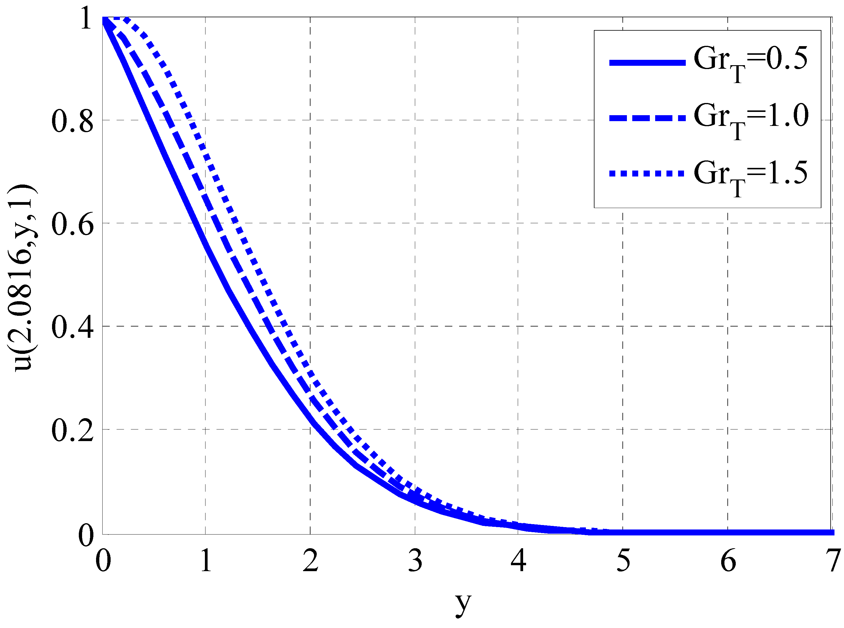
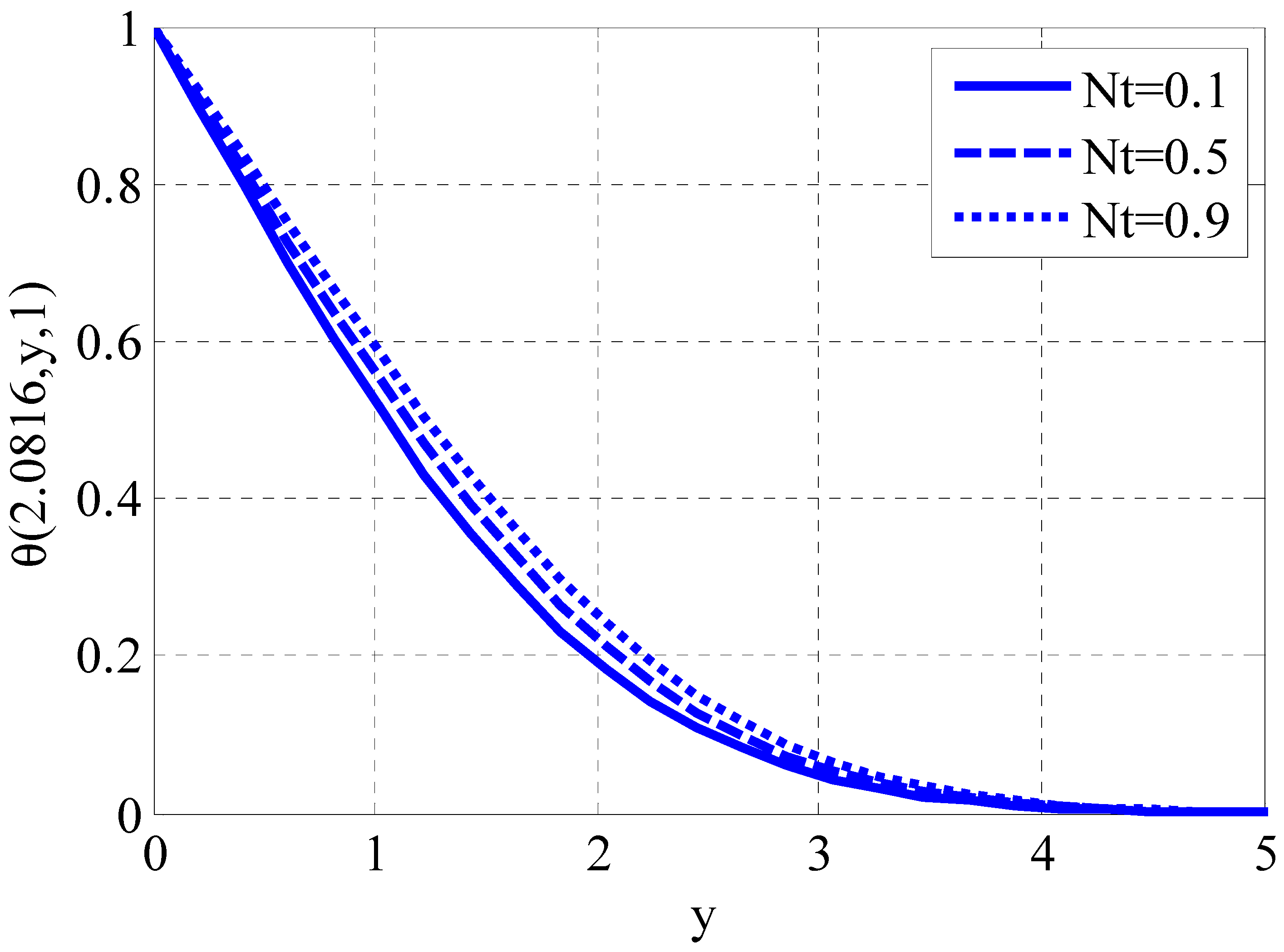
Figure 1 illustrates the impact of parameter I on the velocity profile. The velocity profile increases as parameter I increases. The velocity profile is enhanced since the diffusion process rises as parameter I grows. Figure 2 displays the effect of the Hartman number on the velocity profile. The velocity profile declines as the Hartman number grows. The decline of the velocity profile is the consequence of the increment of the Lorentz force that resists the velocity of the flow. Figure 3 illustrates the change in the thermal Grashof number across the velocity profile. The velocity profile increases as the thermal Grashof number increases. Since the temperature gradient is one of the factors that drive the flow of mixed convective flows, by enhancing the Grashof number, the temperature gradient rises and increases the flow velocity. Figure 4 illustrates the changes in the thermophoresis parameter across the temperature profile. As the thermophoresis parameter increases, the temperature profile also increases. The rise in the temperature profile increases the cycling of hot and cold particles. As the thermophoresis parameter increases, colder particles move closer to the plate, while hotter and lighter particles move away from the plate towards their surroundings. This movement of particles elevates the temperature of the fluid.
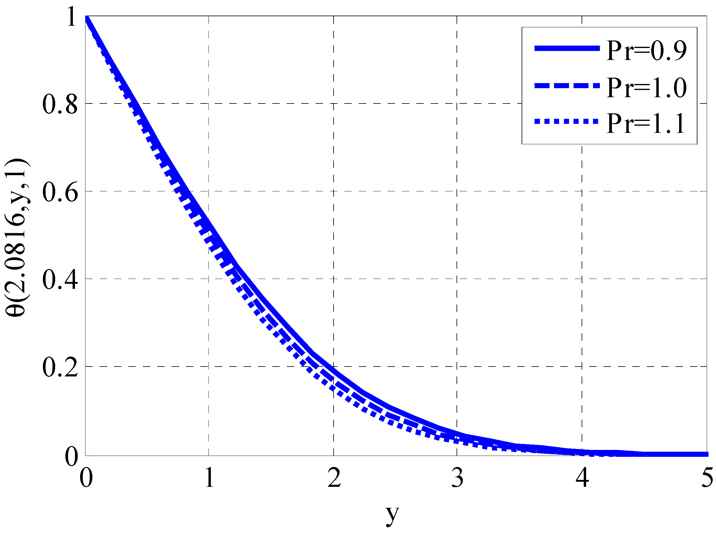
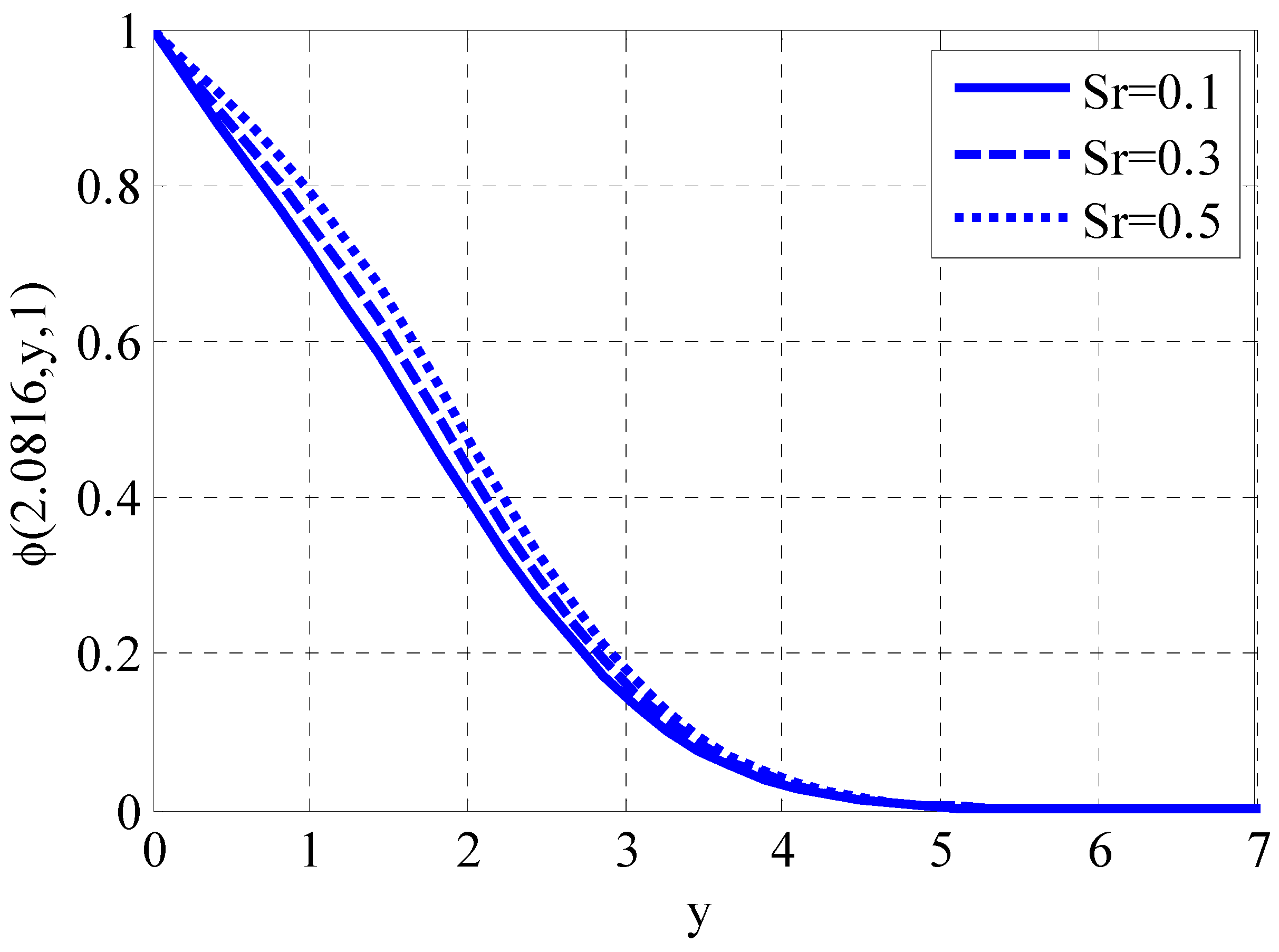
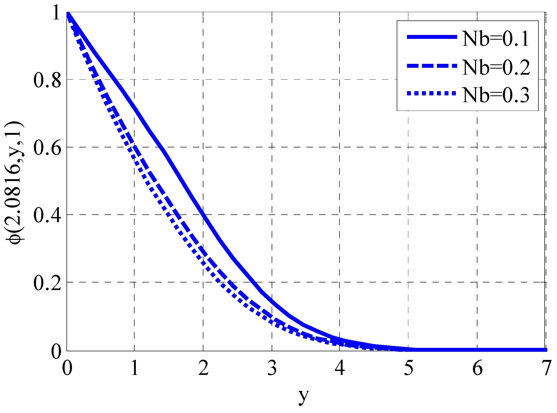
The impact of the Prandtl number on temperature profile is depicted in Figure 5. Temperature profile declines by raising the Prandtl number. The Prandtl number is inversely proportional to thermal diffusivity. A higher Prandtl number causes a lower thermal diffusivity, which in turn leads to a lower thermal conductivity. Consequently, the temperature profile experiences a reduction. The effect of the Soret number on nanoparticle volume fraction is displayed in Figure 6. The nanoparticle volume fraction grows by raising the Soret number. By increasing the Soret number, the nanoparticle volume fraction difference may increase, leading to a rise in nanoparticle volume fraction. Figure 7 shows the Brownian motion parameter on nanoparticle volume fraction. Nanoparticle volume fraction declines by raising the Brownian motion parameter. The difference in nanoparticle volume fraction might increase by incrementing the Brownian motion parameter so that this difference will decrease the nanoparticle volume fraction.
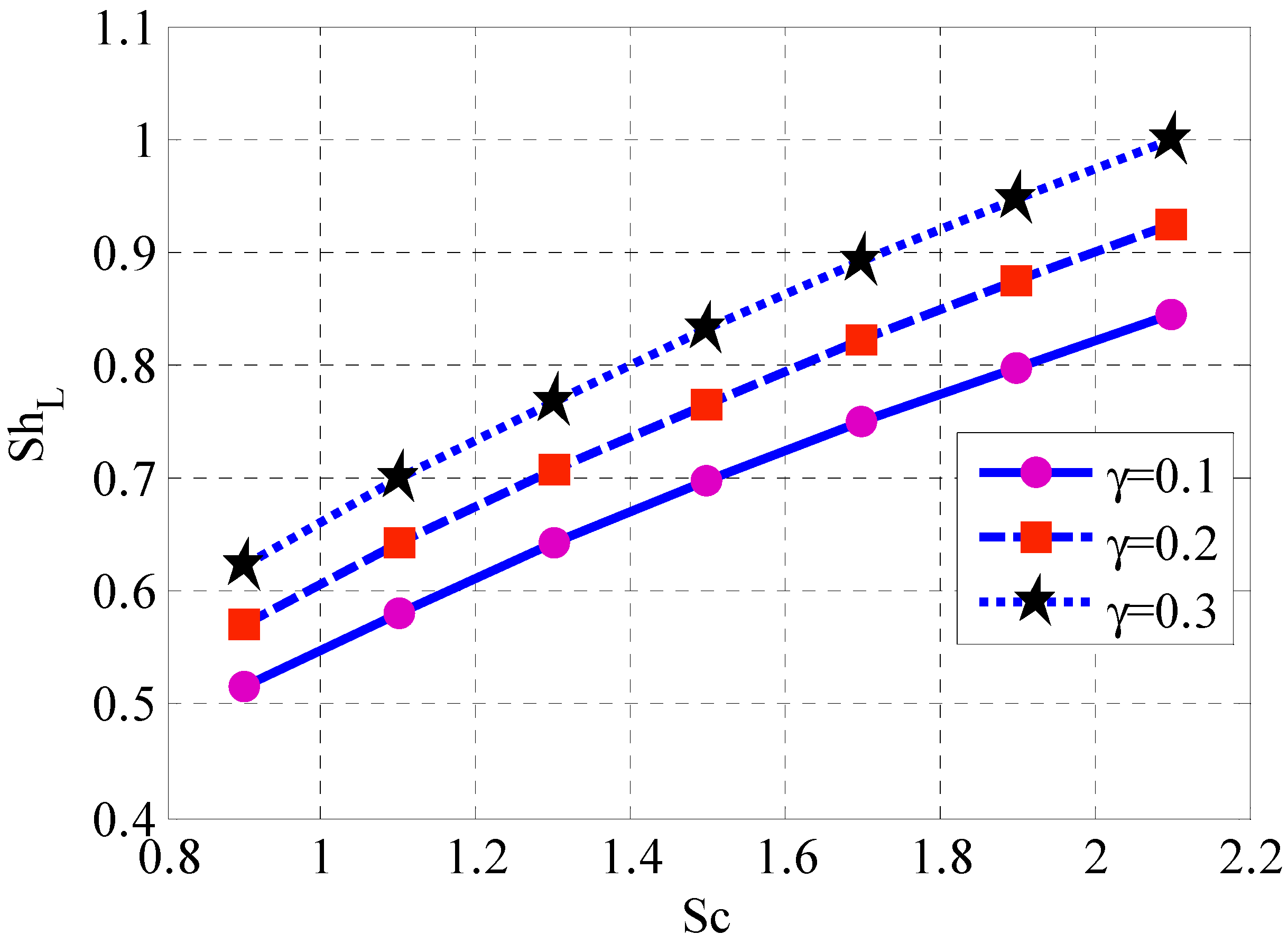
The effect of parameter I and parameter II on the skin friction coefficient is displayed in Figure 8. The skin friction coefficient has both increasing and decreasing behavior by raising parameter I. The skin friction coefficient declines by enhancing parameter II. The effect of the heat source parameter for the space-dependent term and Prandtl number on the local Nusselt number is shown in Figure 9. The Local Nusselt number rises by incrementing the Prandtl number and declines by a raising the coefficient of the dependent term of the heat source. Since the temperature profile rises by raising the heat source parameters and leads to a decrease in heat flux, the local Nusselt number declines. Also, the temperature profile declines by raising the Prandtl number, resulting in heat flux, and so the local Nusselt number rises. Figure 10 shows the influence of the Schmidt number and reaction rate parameter on the local Sherwood number. The local Sherwood number rises as the Schmidt number and reaction rate parameter grows. Since the nanoparticle volume fraction decays by raising the Schmidt number and the reaction rate parameter, this results in growth in mass flux and therefore increases nanoparticle volume fraction.
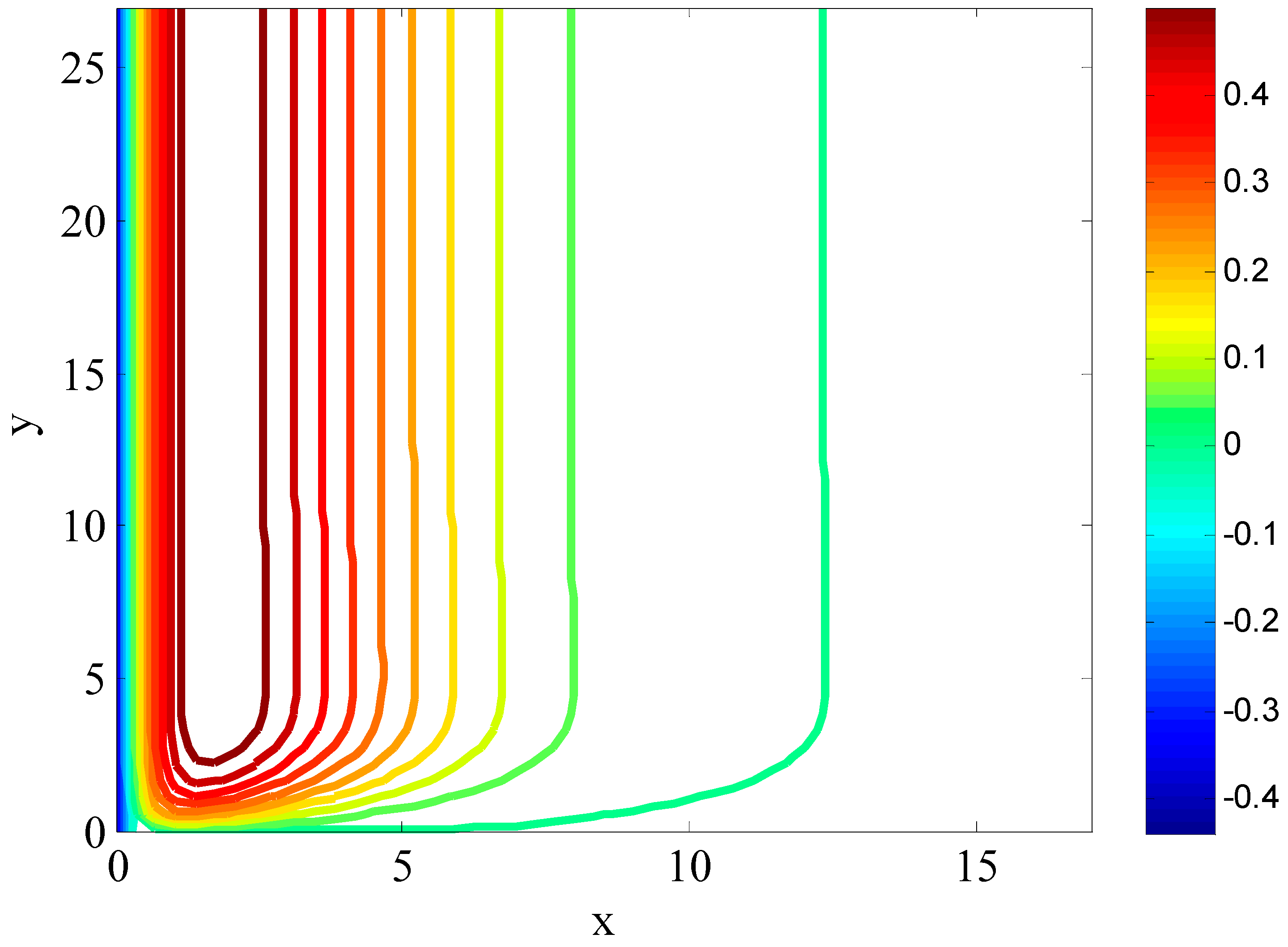
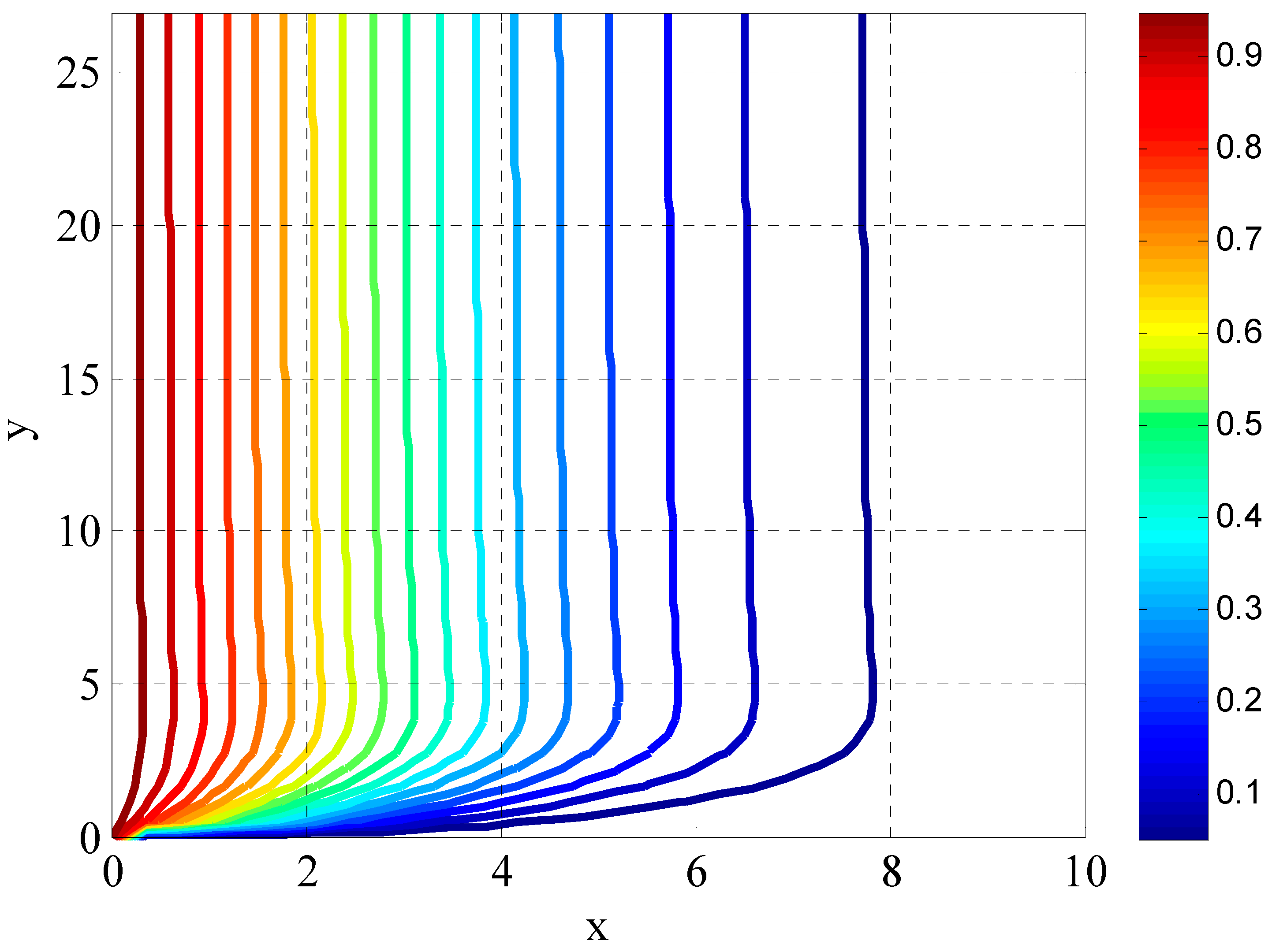
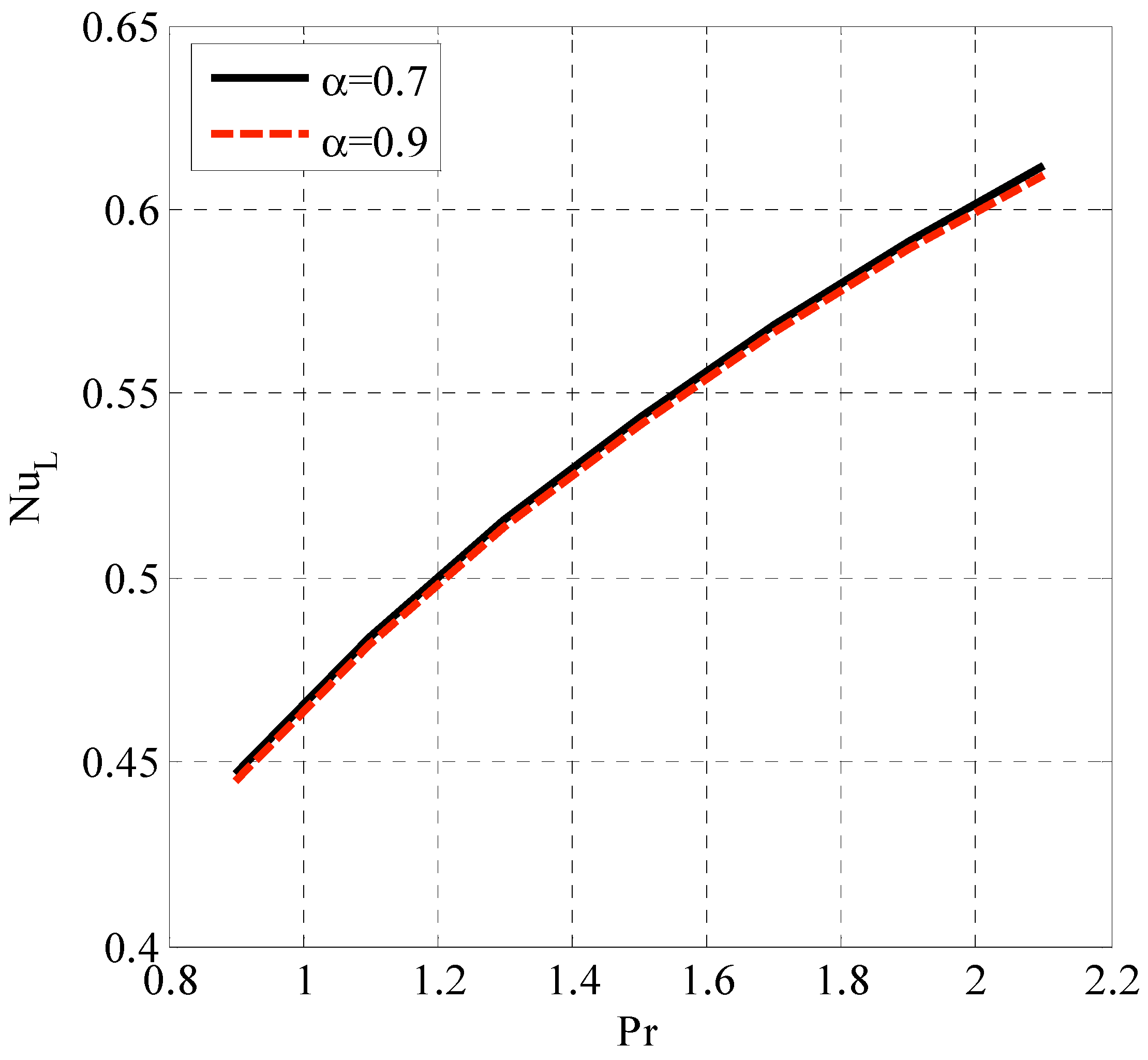
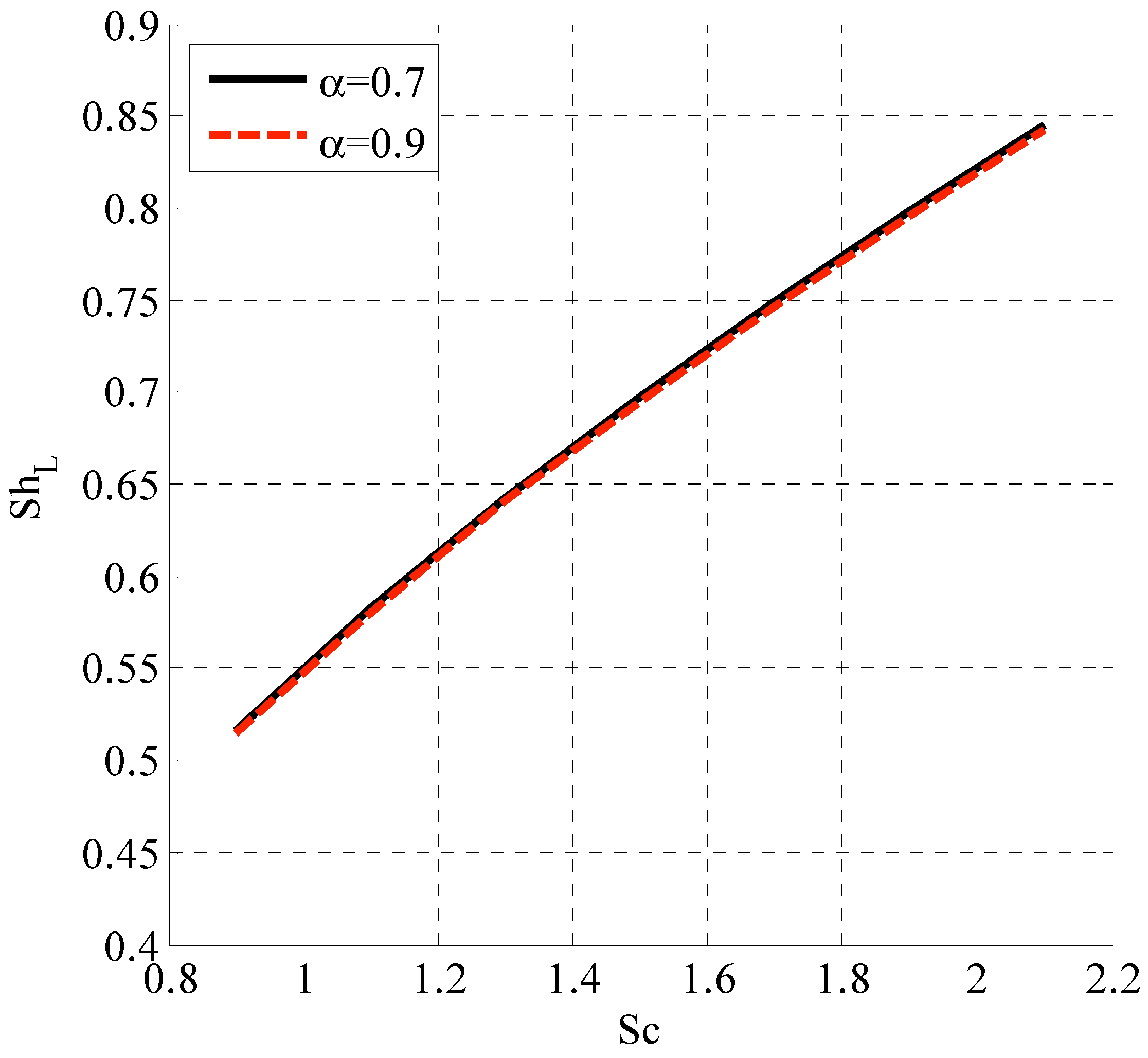
Figure 11, Figure 12 and Figure 13 show the contour plots for the horizontal velocity component and the flow’s temperature profile over an oscillatory sheet. The effect of the oscillatory boundary can be seen in Figure 11, which shows a contour plot over time and spatial coordinates. Since the oscillatory boundary changes by varying time, its effect is clear along time coordinates. Figure 14 and Figure 15 show the effect of different fractal derivatives on local Nusselt numbers and local Sherwood numbers with different values of α , respectively.
Table 2 compares three numerical schemes for solving the two-dimensional parabolic equation, which appeared as the first example in [49]. The suggested scheme exhibits third-order accuracy in the temporal dimension. The forward Euler scheme is the first-order scheme, while the second-order Runge–Kutta scheme is the third. The spatial discretization is carried out using the second-order central difference formula. This comparison demonstrates that the proposed approach yields a lower margin of error compared to the other two alternatives.
Building on our previous discussion of the data, we would want to draw attention to a number of important discoveries and what they mean.
Parametric Analysis and Physical Insights: A comprehensive parametric analysis examined how dimensionless parameters affected velocity, temperature, and nanoparticle volume fraction profiles. Our findings show the complex relationship between these parameters and fluid flow and thermal behavior. The effect of parameters like the Hartman number on velocity profiles shows how magnetic forces resist fluid motion, while thermal Grashof and Prandtl numbers show how temperature gradients and thermal diffusivity affect heat transfer processes.
Comparative Analysis and Validation: The forward Euler and second-order Runge–Kutta systems were compared to our fractal scheme. Our results show that the suggested method improves accuracy and reduces errors for two-dimensional parabolic equations. Our computational technique is validated and emphasized as superior in terms of accuracy and efficiency in this comparative analysis, which advances the state-of-the-art in numerical simulations of complicated fluid dynamics issues.
Integration with State-of-the-Art Research: We will broaden our discussion to incorporate references to current studies that examine similar phenomena or use comparable numerical approaches, allowing for a better contextualization of our findings within the larger framework of fluid dynamics research. Our findings can be better understood in relation to the current state of the art, and our contributions can be more prominently displayed if we compare them to previous literature.

6. Conclusions

This paper studies an explicit computational approach to solve the mixed convective flow of Prandtl-Eyring nanofluid with the effect of space and temperature-dependent heat generation. The proposed three-stage scheme, constructed based on the fractal Taylor series, has proven effective in solving the fractal time-dependent partial differential equations. It is vital to determine the developed scheme’s stability and usefulness. A computational scheme for non-Newtonian Prandtl-Eyring nanofluid flow over solid surfaces has been proposed. Its convergence is also provided for the fractal time-dependent partial differential equations system. The proposed scheme has been employed for fractal time terms, and second-order central difference discretization is used for space discretization. The graphs illustrate the impact of various factors on velocity, temperature, and nanoparticle volume fraction. The concluding points can be stated in the following way:
  • The velocity profile was enhanced as the parameter I grew.
  • The rising coefficient of the space-dependent heat generation term increased the temperature profile.
  • The rising Brownian motion parameter declined the nanoparticle volume fraction.
  • Local Sherwood number increased with Schmidt number and response rate parameter.
By providing a new way to deal with the problems caused by mixed convective flows of nanofluids with non-Newtonian properties, this study adds to the larger area of computational fluid dynamics. The results are more relevant to real-world situations since space and temperature-dependent heat generation are included in the simulations, which makes them more realistic.
Future Directions: A potential future research area could involve expanding the proposed scheme to explore additional sophisticated fluid dynamics scenarios while considering additional parameters and real-world boundary conditions. Extending the proposed scheme to investigate other complex fluid dynamics scenarios, taking into account extra parameters and real-world boundary conditions, could be a future study direction. This study only scratches the surface of the complex parameter interaction within the system; future research may shed light on the system’s behavior and point the way toward better predictive models.
This paper offers a computational framework [50,51,52] to tackle a particular issue in nanofluid mechanics and contributes to the broader field of numerical methods in fluid dynamics. The discoveries provided here provide a basis for future efforts to understand fluid flow’s details in many practical settings, which are crucial for progress in engineering and technology.

Author Contributions

Conceptualization, methodology, and analysis, Y.N.; funding acquisition, A.S.B.; investigation, M.M.; methodology, Y.N.; project administration, K.A.; resources, K.A.; supervision, M.S.A.; visualization, M.M.; writing—review and editing, M.S.A.; proofreading and editing, A.S.B. All authors have read and agreed to the published version of the manuscript.

Funding

The authors would like to acknowledge the support of Prince Sultan University for paying the article processing charges (APC) of this publication.

Data Availability Statement

The manuscript included all required data and implementing information.

Acknowledgments

The authors wish to express their gratitude to Prince Sultan University for facilitating the publication of this article through the Theoretical and Applied Sciences Lab.

Conflicts of Interest

The authors declare no conflict of interest.

References

  1. Aziz, T.; Fatima, A.; Khalique, C.M.; Mahomed, F.M. Prandtl’s boundary layer equation for two-dimensional flow: Exact solutions via the simplest equation method. Math. Probl. Eng. 2013, 2013, 724385. [Google Scholar] [CrossRef]
  2. Sankad, G.; Ishwar, M.; Dhange, M. Varying wall temperature and thermal radiation effects on MHD boundary layer liquid flow containing gyrotactic microorganisms. Partial. Differ. Equ. Appl. Math. 2021, 4, 100092. [Google Scholar]
  3. Hussain, M.; Ghaffar, A.; Ali, A.; Shahzad, A.; Nisar, K.S.; Alharthi, M.R.; Jamshed, W. MHD thermal boundary layer flow of a Casson fluid over a penetrable stretching wedge in the existence of nonlinear radiation and convective boundary condition. Alex. Eng. J. 2021, 60, 5473–5483. [Google Scholar] [CrossRef]
  4. Abedi, H.; Sarkar, S.; Johansson, H. Numerical modelling of neutral atmospheric boundary layer flow through heterogeneous forest canopies in complex terrain (a case study of a Swedish wind farm). Renew. Energy 2021, 180, 806–828. [Google Scholar] [CrossRef]
  5. Yang, S.; Liu, L.; Long, Z.; Feng, L. Unsteady natural convection boundary layer flow and heat transfer past a vertical flat plate with novel constitution models. Appl. Math. Lett. 2021, 120, 107335. [Google Scholar] [CrossRef]
  6. Long, Z.; Liu, L.; Yang, S.; Feng, L.; Zheng, L. Analysis of Marangoni boundary layer flow and heat transfer with novel constitution relationships. Int. Commun. Heat Mass Transf. 2021, 127, 105523. [Google Scholar] [CrossRef]
  7. Zhang, X.; Tang, Y.; Zhang, F.; Lee, C.S. A novel aluminum—Graphite dual-ion battery. Adv. Energy Mater. 2016, 6, 1502588. [Google Scholar] [CrossRef]
  8. Hosseini, S.M.; Safaei, M.R.; Goodarzi, M.; Alrashed, A.A.; Nguyen, T.K. New temperature, interfacial shell dependent dimensionless model for thermal conductivity of nanofluids. Int. J. Heat Mass Transf. 2017, 114, 207–210. [Google Scholar] [CrossRef]
  9. Ahmadi, M.H.; Mohseni-Gharyehsafa, B.; Ghazvini, M.; Goodarzi, M.; Jilte, R.D.; Kumar, R. Comparing various machine learning approaches in modeling the dynamic viscosity of CuO/water nanofluid. J. Therm. Anal. Calorim. 2020, 139, 2585–2599. [Google Scholar] [CrossRef]
  10. Bahiraei, M.; Salmi, H.K.; Safaei, M.R. Effect of employing a new biological nanofluid containing functionalized graphene nanoplatelets on thermal and hydraulic characteristics of a spiral heat exchanger. Energy Convers. Manag. 2019, 180, 72–82. [Google Scholar] [CrossRef]
  11. Waqas, H.; Farooq, U.; Khan, S.A.; Alshehri, H.M.; Goodarzi, M. Numerical analysis of dual variable of conductivity in bioconvection flow of Carreau–Yasuda nanofluid containing gyrotactic motile microorganisms over a porous medium. J. Therm. Anal. Calorim. 2021, 145, 2033–2044. [Google Scholar] [CrossRef]
  12. Wang, X.; Li, C.; Zhang, Y.; Said, Z.; Debnath, S.; Sharma, S.; Yang, M.; Gao, T. Influence of texture shape and arrangement on nanofluid minimum quantity lubrication turning. Int. J. Adv. Manuf. Technol. 2021, 119, 631–646. [Google Scholar] [CrossRef]
  13. Xie, Y.; Meng, X.; Mao, D.; Qin, Z.; Wan, L.; Huang, Y. Homogeneously dispersed graphene nanoplatelets as long-term corrosion inhibitors for aluminum matrix composites. ACS Appl. Mater. Interfaces 2021, 13, 32161–32174. [Google Scholar] [CrossRef] [PubMed]
  14. Abu-Hamdeh, N.H.; Alsulami, R.A.; Rawa, M.J.; Alazwari, M.A.; Goodarzi, M.; Safaei, M.R. A Significant Solar Energy Note on Powell-Eyring Nanofluid with Thermal Jump Conditions: Implementing Cattaneo-Christov Heat Flux Model. Mathematics 2021, 9, 2669. [Google Scholar] [CrossRef]
  15. Sajid, T.; Jamshed, W.; Shahzad, F.; Eid, M.R.; Alshehri, H.M.; Goodarzi, M.; Akgül, E.K.; Nisar, K.S. Micropolar fluid past a convectively heated surface embedded with nth order chemical reaction and heat source/sink. Phys. Scr. 2021, 96, 104010. [Google Scholar] [CrossRef]
  16. Maleki, H.; Safaei, M.R.; Togun, H.; Dahari, M. Heat transfer and fluid flow of pseudo-plastic nanofluid over a moving permeable plate with viscous dissipation and heat absorption/generation. J. Therm. Anal. Calorim. 2019, 135, 1643–1654. [Google Scholar] [CrossRef]
  17. Shankar, U.; Naduvinamani, N. Magnetized squeezed flow of time-dependent Prandtl-Eyring fluid past a sensor surface. Heat Transf. Asian Res. 2019, 48, 2237–2261. [Google Scholar] [CrossRef]
  18. Al-Kaabi, W.; Al-Khafajy, D.G.S. Radiation and Mass Transfer Effects on Inclined MHD Oscillatory Flow for Prandtl-Eyring Fluid through a Porous Channel. Al-Qadisiyah J. Pure Sci. 2021, 26, 347–363. [Google Scholar]
  19. Hayat, T.; Ullah, I.; Muhammad, K.; Alsaedi, A. Gyrotactic microorganism and bio-convection during flow of Prandtl-Eyring nanomaterial. Nonlinear Eng. 2021, 10, 201–212. [Google Scholar] [CrossRef]
  20. Waqas, H.; Farooq, U.; Alshehri, H.M.; Goodarzi, M. Marangoni-bioconvectional flow of Reiner–Philippoff nanofluid with melting phenomenon and nonuniform heat source/sink in the presence of a swimming microorganisms. Math. Methods Appl. Sci. 2021. [Google Scholar] [CrossRef]
  21. Alazwari, M.A.; Abu-Hamdeh, N.H.; Goodarzi, M. Entropy Optimization of First-Grade Viscoelastic Nanofluid Flow over a Stretching Sheet by Using Classical Keller-Box Scheme. Mathematics 2021, 9, 2563. [Google Scholar] [CrossRef]
  22. Munjam, S.R.; Gangadhar, K.; Seshadri, R.; Rajeswar, M. Novel technique MDDIM solutions of MHD flow and radiative Prandtl-Eyring fluid over a stretching sheet with convective heating. Int. J. Ambient. Energy 2021, 43, 4850–4859. [Google Scholar] [CrossRef]
  23. Jamshed, W.; Kumar, V.; Kumar, V. Computational examination of Casson nanofluid due to a nonlinear stretching sheet subjected to particle shape factor: Tiwari and Das model. Numer. Methods Partial. Differ. Equ. 2020, 38, 848–875. [Google Scholar] [CrossRef]
  24. Jamshed, W.; Mishra, S.; Pattnaik, P.; Nisar, K.S.; Devi, S.S.U.; Prakash, M.; Shahzad, F.; Hussain, M.; Vijayakumar, V. Features of entropy optimization on viscous second grade nanofluid streamed with thermal radiation: A Tiwari and Das model. Case Stud. Therm. Eng. 2021, 27, 101291. [Google Scholar] [CrossRef]
  25. Abdelmalek, Z.; Hussain, A.; Bilal, S.; Sherif, E.-S.M.; Thounthong, P. Brownian motion and thermophoretic diffusion influence on thermophysical aspects of electrically conducting viscoinelastic nanofluid flow over a stretched surface. J. Mater. Res. Technol. 2020, 9, 11948–11957. [Google Scholar] [CrossRef]
  26. Pan, M.; Zheng, L.; Liu, F.; Zhang, X. Modeling heat transport in nanofluids with stagnation point flow using fractional calculus. Appl. Math. Model. 2016, 40, 8974–8984. [Google Scholar] [CrossRef]
  27. Li, S.N.; Cao, B.Y. Fractional Boltzmann transport equation for anomalous heat transport and divergent thermal conductivity. Int. J. Heat Mass Transf. 2019, 137, 84–89. [Google Scholar] [CrossRef]
  28. Santina, D.; Asif, M.; Aljawi, S.; Mlaiki, N. Application of the inverse Laplace transform techniques to solve the generalized Bagley–Torvik equation including Caputo’s fractional derivative. Partial. Differ. Equ. Appl. Math. 2024, 10, 100664. [Google Scholar] [CrossRef]
  29. Chen, X.; Ye, Y.; Zhang, X.; Zheng, L. Lie-group similarity solution and analysis for fractional viscoelastic MHD fluid over a stretching sheet. Comput. Math. Appl. 2018, 75, 3002–3011. [Google Scholar] [CrossRef]
  30. Caputo, M. Linear models of dissipation whose Q is almost frequency independent. Ann. Geophys. 1966, 19, 383–393. [Google Scholar] [CrossRef]
  31. Chakrabarty, A.K.; Roshid, M.M.; Rahaman, M.M.; Abdeljawad, T.; Osman, M.S. Dynamical analysis of optical soliton solutions for CGL equation with Kerr law nonlinearity in classical, truncated M-fractional derivative, beta fractional derivative, and conformable fractional derivative types. Results Phys. 2024, 60, 107636. [Google Scholar] [CrossRef]
  32. Asjad, M.I.; Sarwar, N.; Hafeez, M.B.; Sumelka, W.; Muhammad, T. Advancement of non-newtonian fluid with hybrid nanoparticles in a convective channel and prabhakar’s fractional derivative—Analytical solution. Fractal Fract. 2021, 5, 99. [Google Scholar] [CrossRef]
  33. Asjad, M.I.; Ali, R.; Iqbal, A.; Muhammad, T.; Chu, Y.M. Application of water based drilling clay-nanoparticles in heat transfer of fractional Maxwell fluid over an infinite flat surface. Sci. Rep. 2021, 11, 25. [Google Scholar] [CrossRef]
  34. Asjad, M.I.; Basit, A.; Iqbal, A.; Shah, N.A. Advances in transport phenomena with nanoparticles and generalized thermal process for vertical plate. Phys. Scr. 2021, 96, 15. [Google Scholar] [CrossRef]
  35. Pan, M.; Zheng, L.; Liu, F.; Liu, C.; Chen, X. A spatial-fractional thermal transport model for nanofluid in porous media. Appl. Math. Model. 2018, 53, 622–634. [Google Scholar] [CrossRef]
  36. Tassaddiq, A. MHD flow of a fractional second grade fluid over an inclined heated plate. Chaos Solitons Fractals 2019, 123, 341–346. [Google Scholar] [CrossRef]
  37. Chen, X.; Yang, W.; Zhang, X.; Liu, F. Unsteady boundary layer flow of viscoelastic MHD fluid with a double fractional Maxwell model. Appl. Math. Lett. 2019, 95, 143–149. [Google Scholar] [CrossRef]
  38. Yang, W.; Chen, X.; Zhang, X.; Zheng, L.; Liu, F. Flow and heat transfer of double fractional Maxwell fluids over a stretching sheet with variable thickness. Appl. Math. Model. 2020, 80, 204–216. [Google Scholar] [CrossRef]
  39. Li, B.; Liu, F. Boundary layer flows of viscoelastic fluids over a non-uniform permeable surface. Comput. Math. Appl. 2020, 79, 2376–2387. [Google Scholar] [CrossRef]
  40. Shen, M.; Chen, L.; Zhang, M.; Liu, F. A renovated Buongiorno’s model for unsteady Sisko nanofluid with fractional Cattaneo heat flux. Int. J. Heat Mass Transf. 2018, 126, 277–286. [Google Scholar] [CrossRef]
  41. Liu, L.; Feng, L.; Xu, Q.; Zheng, L.; Liu, F. Flow and heat transfer of generalized Maxwell fluid over a moving plate with distributed order time fractional constitutive models. Int. Commun. Heat Mass Transf. 2020, 116, 415. [Google Scholar] [CrossRef]
  42. Anwar, M.S.; Ahmad, R.T.M.; Shahzad, T.; Irfan, M.; Ashraf, M.Z. Electrified fractional nanofluid flow with suspended carbon nanotubes. Comput. Math. Appl. 2020, 80, 1375–1386. [Google Scholar] [CrossRef]
  43. Sun, Z.Z.; Wu, X. A fully discrete difference scheme for a diffusion-wave system. Appl. Numer. Math. 2006, 56, 193–209. [Google Scholar] [CrossRef]
  44. She, M.; Li, D.; Sun, H.W. A transformed L1 method for solving the multi-term time-fractional diffusion problem. Math. Comput. Simul. 2022, 193, 584–606. [Google Scholar] [CrossRef]
  45. Yuan, W.; Li, D.; Zhang, C. Linearized Transformed L1 Galerkin FEMs with Unconditional Convergence for Nonlinear Time Fractional Schrödinger Equations. Numer. Math. Theory Methods Appl. 2023, 16, 348–369. [Google Scholar] [CrossRef]
  46. Lu, Z.; Fan, W. A fast algorithm for multi-term time-space fractional diffusion equation with fractional boundary condition. Numer. Algorithms 2024, 1–24. [Google Scholar] [CrossRef]
  47. Chen, W.; Sun, H.; Zhang, X.; Korošak, D. Anomalous diffusion modeling by fractal and fractional derivatives. Comput. Math. Appl. 2010, 59, 1754–1758. [Google Scholar] [CrossRef]
  48. Khan, Z.A.; Shah, K.; Abdalla, B.; Abdeljawad, T. A numerical Study of Complex Dynamics of a Chemostat Model Under Fractal-Fractional Derivative. Fractals 2023, 31, 2340181. [Google Scholar] [CrossRef]
  49. Li, F.-l.; Wu, Z.-k.; Ye, C.-r. A finite difference solution to a two-dimensional parabolic inverse problem. Appl. Math. Model. 2012, 36, 2303–2313. [Google Scholar] [CrossRef]
  50. Arif, M.S.; Abodayeh, K.; Nawaz, Y. A finite difference explicit-implicit scheme for fractal heat and mass transportation of Williamson nanofluid flow in quantum calculus. Numer. Heat Transf. Part A Appl. 2024, 1–23. [Google Scholar] [CrossRef]
  51. Arif, M.S.; Abodayeh, K.; Nawaz, Y. The modified finite element method for heat and mass transfer of unsteady reacting flow with mixed convection. Front. Phys. 2022, 10, 952787. [Google Scholar] [CrossRef]
  52. Nawaz, Y.; Arif, M.S.; Abodayeh, K. An explicit-implicit numerical scheme for time fractional boundary layer flows. Int. J. Numer. Methods Fluids 2022, 94, 920–940. [Google Scholar] [CrossRef]
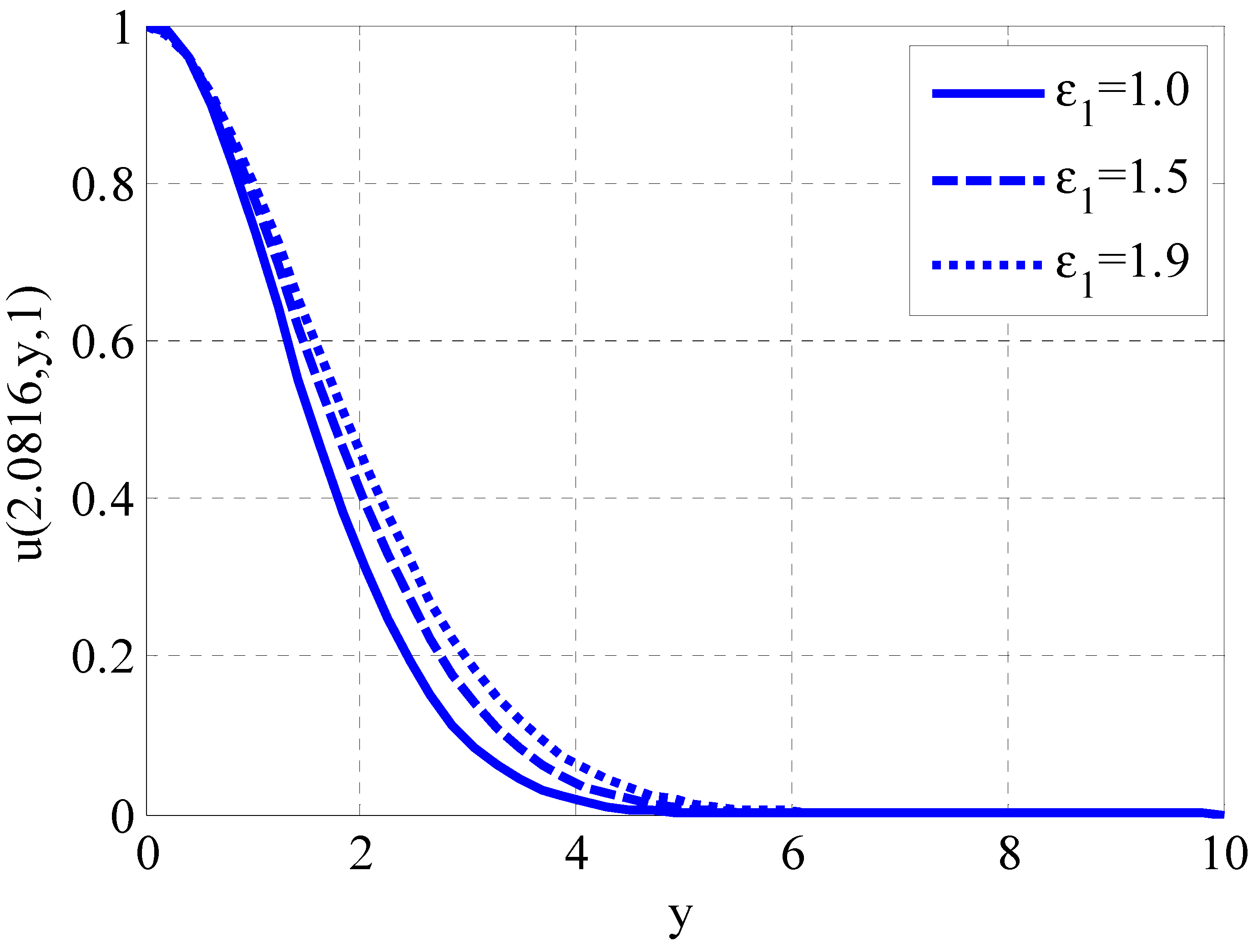
Figure 1. Effect of parameter I on velocity profile using R e = 1 , ε 2 = 0.01 , ε = 0.1 , A * = 0.1 , B * = 0.1 , H 0 = 0.1 , N t = 0.1 , N b = 0.1 , S r = 0.1 , G r T = 0.5 , G r C = 0.5 , P r = 0.9 , S c = 0.9 , γ = 0.1 , α = 1 .
Fractalfract 08 00276 g001
Figure 2. Effect of Hartmann number on velocity profile using R e = 1 , ε 2 = 0.01 , ε = 0.1 , A * = 0.1 , B * = 0.1 , ε 1 = 1 , N t = 0.1 , N b = 0.1 , S r = 0.1 , G r T = 0.5 , G r C = 0.5 , P r = 0.9 , S c = 0.9 , γ = 0.1 , α = 0.7 .
Fractalfract 08 00276 g002
Figure 3. Effect of thermal Grashof number on velocity profile using R e = 1 , ε 2 = 0.01 , ε = 0.1 , A * = 0.1 , B * = 0.1 , ε 1 = 1 , N t = 0.1 , N b = 0.1 , S r = 0.1 , H 0 = 0.9 , G r C = 0.5 , P r = 0.9 , S c = 0.9 , γ = 0.1 , α = 0.7 .
Fractalfract 08 00276 g003
Figure 4. Effect of thermophoresis parameter on temperature profile using R e = 1 , ε 2 = 0.01 , ε = 0.1 , A * = 0.1 , B * = 0.1 , ε 1 = 1 , G r T = 0.5 , N b = 0.1 , S r = 0.1 , H 0 = 0.9 , G r C = 0.5 , P r = 0.9 , S c = 0.9 , γ = 0.1 , α = 0.7 .
Fractalfract 08 00276 g004
Figure 5. Effect of Prandtl number on temperature profile using R e = 1 , ε 2 = 0.01 , ε = 0.1 , A * = 0.1 , B * = 0.1 , ε 1 = 1 , G r T = 0.5 , N b = 0.1 , S r = 0.1 , H 0 = 0.9 , G r C = 0.5 , N t = 0.1 , S c = 0.9 , γ = 0.1 , α = 0.7 .
Fractalfract 08 00276 g005
Figure 6. Effect of Soret number on nanoparticle volume fraction profile using R e = 1 , ε 2 = 0.01 , ε = 0.1 , A * = 0.1 , B * = 0.1 , ε 1 = 1 , G r T = 0.5 , N b = 0.1 , P r = 1.1 , H 0 = 0.9 , G r C = 0.5 , N t = 0.1 , S c = 0.9 , γ = 0.1 , α = 0.7 .
Fractalfract 08 00276 g006
Figure 7. Effect of Brownian motion parameter on nanoparticle volume fraction profile using R e = 1 , ε 2 = 0.01 , ε = 0.1 , A * = 0.1 , B * = 0.1 , ε 1 = 1 , G r T = 0.5 , S r = 0.1 , P r = 1.1 , H 0 = 0.9 , G r C = 0.5 , N t = 0.1 , S c = 0.9 , γ = 0.1 , α = 0.7 .
Fractalfract 08 00276 g007
Figure 8. Effect of parameter I and parameter II on skin friction coefficient using R e = 1 , ε = 0.1 , A * = 0.1 , B * = 0.1 , N b = 0.3 , G r T = 1.5 , S r = 0.1 , P r = 0.9 , H 0 = 0.9 , G r C = 0.5 , N t = 0.1 , S c = 0.9 , γ = 0.1 , α = 0.7 .
Fractalfract 08 00276 g008
Figure 9. Effect of coefficient of space-dependent term of heat generation and Prandtl number on local Nusselt number using R e = 1 , ε = 0.1 , ε 1 = 1 , B * = 0.1 , N b = 0.3 , G r T = 0.5 , S r = 0.1 , ε 2 = 0.01 , H 0 = 0.9 , G r C = 0.5 , N t = 0.1 , S c = 0.9 , γ = 0.1 , α = 0.7 .
Fractalfract 08 00276 g009
Figure 10. Effect of Schmidt number and reaction rate parameter on local Sherwood number using R e = 1 , ε = 0.1 , ε 1 = 1 , B * = 0.1 , N b = 0.3 , G r T = 0.5 , S r = 0.1 , ε 2 = 0.01 , H 0 = 0.9 , G r C = 0.5 , N t = 0.1 , P r = 0.9 , A * = 0.5 , α = 0.7 .
Fractalfract 08 00276 g010
Figure 11. Contour plot for the horizontal component of velocity along time and spatial coordinates using R e = 1 , ε = 0.1 , ε 1 = 1 , B * = 0.1 , N b = 0.3 , G r T = 0.5 , S r = 0.1 , ε 2 = 0.01 , H 0 = 0.9 , G r C = 0.5 , N t = 0.1 , P r = 0.9 , A * = 0.5 , S c = 0.9 , γ = 0.1 α = 0.7 , u w = c o s t s i n t , x L ( L e n g t h   o f   b o u n d a r y   f o r   x ) = 27 , y L ( L e n g t h   o f   b o u n d a r y   f o r   y ) = 17 .
Fractalfract 08 00276 g011
Figure 12. Contour plot for the horizontal component of velocity along spatial coordinates using R e = 1 , ε = 0.1 , ε 1 = 1 , B * = 0.1 , N b = 0.3 , G r T = 0.5 , S r = 0.1 , ε 2 = 0.01 , H 0 = 0.9 , G r C = 0.5 , N t = 0.1 , P r = 0.9 , A * = 0.5 , S c = 0.9 , γ = 0.1 α = 0.7 , u w = c o s t s i n t , x L ( L e n g t h   o f   b o u n d a r y   f o r   x ) = 27 , y L ( L e n g t h   o f   b o u n d a r y   f o r   y ) = 17 .
Fractalfract 08 00276 g012
Figure 13. Contour plot for temperature profile along spatial coordinates using R e = 1 , ε = 0.1 , ε 1 = 1 , B * = 0.1 , N b = 0.3 , G r T = 0.5 , S r = 0.1 , ε 2 = 0.01 , H 0 = 0.9 , G r C = 0.5 , N t = 0.1 , P r = 0.9 , A * = 0.5 , S c = 0.9 , γ = 0.1 α = 0.7 , u w = c o s t s i n t , x L ( L e n g t h   o f   b o u n d a r y   f o r   x ) = 27 , y L ( L e n g t h   o f   b o u n d a r y   f o r   y ) = 17 .
Fractalfract 08 00276 g013
Figure 14. Variation of fractal derivative parameter on local Nusselt number using R e = 1 , ε = 0.1 , ε 1 = 1 , B * = 0.1 , N b = 0.3 , G r T = 0.5 , S r = 0.1 , ε 2 = 0.01 , H 0 = 0.9 , G r C = 0.5 , N t = 0.1 , A * = 0.5 , S c = 0.9 , γ = 0.1 α = 0.7 , u w = 1 , x L ( L e n g t h   o f   b o u n d a r y   f o r   x ) = 17 , y L ( L e n g t h   o f   b o u n d a r y   f o r   y ) = 10 .
Fractalfract 08 00276 g014
Figure 15. Variation of fractal derivative parameter on local Sherwood number using R e = 1 , ε = 0.1 , ε 1 = 1 , B * = 0.1 , N b = 0.3 , G r T = 0.5 , S r = 0.1 , ε 2 = 0.01 , H 0 = 0.9 , G r C = 0.5 , N t = 0.1 , A * = 0.5 , P r = 0.9 , γ = 0.1 α = 0.7 , u w = 1 , x L ( L e n g t h   o f   b o u n d a r y   f o r   x ) = 17 , y L ( L e n g t h   o f   b o u n d a r y   f o r   y ) = 10 .
Fractalfract 08 00276 g015
Table 1. Fractional derivatives have been studied from numerous aspects in boundary layer problems.
FluidType of DerivativeType of Magnetic FieldType of SolutionResearchersCase Study
Single nanofluid (Water-CuWater-Ag Water- A l 2 O 3 Water- T i O 2 )Spatial fractionalWithout magnetic fieldNumerical (finite difference)Pan et al. [35]Boundary layer flow in a porous media
Second-grade fluidTime fractionalInclined magnetic fieldNumerical (Laplace along with Zakian’s algorithm)Tassaddiq [36]Boundary layer flow along an inclined heated plate
Viscoelastic fluidTime fractionalVertical magnetic fieldNumerical (finite difference)Chen et al. [37]Boundary layer flow over a stretching sheet
Maxwell fluidTime fractionalWithout magnetic fieldNumerical (finite difference)Yang et al. [38]Stretching sheet with variable thickness
Viscoelastic fluidSpatial fractionalWithout magnetic fieldNumerical (finite difference)Li et al. [39]Boundary layer over a permeable surface
Sisko nanofluidTime fractionalWithout magnetic fieldNumerical (finite difference)Shen et al. [40]Boundary layer flow over a continuously moving plate
Maxwell fluidTime fractionalWithout magnetic fieldNumerical (finite difference)Liu et al. [41]Boundary layer over a moving plate
Single nanofluid (Water-SWCNTs Water-MWCNTs)Time fractionalVertical magnetic fieldNumerical (Joint of finite-difference discretization and L1 algorithm)Anwar et al. [42]Boundary layer flow induced due to a stretching sheet
Table 2. Comparison of three schemes using N x = 50 = N y ( N o . o f   g r i d   p o i n t s )   t f ( F i n a l   T i m e ) = 0.1 .
t Proposed1st Order Scheme2nd Order Scheme
L 2 ErrorConv. Order L 2 ErrorConv. Order L 2 ErrorConv. Order
0.1 1500 4.27 × 10⁻⁴-6.29 × 10⁻⁴-5.31 × 10⁻⁴-
0.1 1750 4.19 × 10−40.12275.93 × 10−40.38235.09 × 10−40.2745
0.1 2000 4.13 × 10−40.10805.66 × 10−40.34904.92 × 10−41.2805
0.1 2250 4.09 × 10−40.08265.45 × 10−40.32104.79 × 10−40.2274
Disclaimer/Publisher’s Note: The statements, opinions and data contained in all publications are solely those of the individual author(s) and contributor(s) and not of MDPI and/or the editor(s). MDPI and/or the editor(s) disclaim responsibility for any injury to people or property resulting from any ideas, methods, instructions or products referred to in the content.