Abstract
This work investigates a fractional-order multi-wing chaotic system for detecting weak signals. The influence of the order of fractional calculus on chaotic systems’ dynamical behavior is examined using phase diagrams, bifurcation diagrams, and SE complexity diagrams. Then, the principles and methods for determining the frequencies and amplitudes of weak signals are examined utilizing fractional-order multi-wing chaotic systems. The findings indicate that the lowest order at which this kind of fractional-order multi-wing chaotic system appears chaotic is at , , and , and that this value decreases as the driving force increases. The four-wing and double-wing change dynamics phenomenon will manifest in a fractional-order chaotic system when the order exceeds the lowest order. This phenomenon can be utilized to detect weak signal amplitudes and frequencies because the system parameters control it. A detection array is built to determine the amplitude using the noise-resistant properties of both four-wing and double-wing chaotic states. Deep learning images are then used to identify the change in the array’s wing count, which can be used to determine the test signal’s amplitude. When frequencies detection is required, the MUSIC method estimates the frequencies using chaotic synchronization to transform the weak signal’s frequencies to the synchronization error’s frequencies. This solution adds to the contact between fractional-order calculus and chaos theory. It offers suggestions for practically implementing the chaotic weak signal detection theory in conjunction with deep learning.
1. Introduction
As a nonlinear signal detection method, chaotic weak signal detection has been studied for over thirty years. The difference between the chaotic system method and other classical signal processing techniques is that chaotic systems can resist noise through iteration. This allows the noise to be much larger than weak signals and achieve a negative signal-to-noise ratio, which is already superior to the most common amplification methods. Among numerous weak signal detection methods that can handle noise, the detection performance of chaotic detection methods is related to the design of chaotic systems. By increasing the effective number of control parameters in chaotic systems, weaker, smaller signals can be detected, resulting in higher detection performance limits. Since Birx [1] proved in 1992 that the Duffing chaotic system can be used for weak signal detection, he is considered the pioneer of the theory of chaotic weak signal detection. Wang [2] continued his work on Birx by showing how to detect weak signals using the initial value sensitivity property of the Duffing system and gave a complete procedure for doing so. In recent years, researchers have kept a close eye on Duffing systems for weak signal detection, and several novel theories for gauging the signal detection capability have emerged [3,4,5,6,7]. Meanwhile, many practical problems have been resolved by applying chaotic weak signal detection approaches [8,9,10]. This shows that the subject of chaos-based weak signal identification has gained popularity in engineering applications and can potentially tackle problems that are not well-suited for linear signal detection.
Researchers have employed more chaotic systems to detect signals and have also found solutions to a few real-world issues to enhance the detection performance further [11,12,13,14,15,16,17,18]. Furthermore, the multi-wing chaotic system has a distinct attractor topology beyond these additional systems. As a result, this chaotic system likewise displays extremely complicated features [19,20,21,22,23,24], which naturally prompts researchers to think of using it for the detection of weak signals. Li [25] created a nonlinear feedback controller from chaotic synchronization, stabilized the chaotic system with many wings to the equilibrium point, and then used the chaotic system’s synchronized state to detect weak signals with multiple frequencies. In Yan’s [26] study of a multi-wing chaotic system with an infinite number of equilibrium points, he found that weak signals might be identified by comparing the fluctuations between four-wing and two-wing chaotic attractors. The viability and superiority of employing a multi-wing chaotic system for weak signal identification are amply illustrated by these works.
Due to advancements in chaos theory, fractional-order chaotic systems have grown in importance within the field of chaos. Additionally, fractional-order calculus has introduced new features to the field, making fractional-order chaotic systems highly relevant as a research hotspot with significant potential for engineering applications [27,28,29,30,31]. In all chaotic applications, fractional-order chaotic systems for the detection of weak signals have emerged as a state-of-the-art part of chaotic weak signal detection [32,33,34,35,36].
Although fractional-order multi-wing systems have been partially studied and applied [37,38,39,40], research on how to use such systems for weak signal detection is rare, especially in demonstrating the advantages of fractional calculus. Secondly, how to apply the existing theory of chaotic weak signal detection to practical device design is also a major obstacle to the development of this theory. Finally, deep learning image recognition is a very mature technology, and in the state criteria of chaotic systems, the attractor graph method is a classic method. However, the development of combining the attractor graph method with deep learning image recognition and introducing deep learning into chaotic weak signal detection is still blank.
Therefore, in order to address the above issues, in this paper, we researched the application of fractional-order multi-wing chaotic systems in weak signal detection. Firstly, the multi-wing chaotic system will be rewritten into the fractional-order form, because the fractional-order system is more consistent with the actual physical model. Then the influence of order parameters in fractional-order calculus on the characteristics of chaotic systems is analyzed. Lastly, weak signal detection was accomplished using this fractional-order chaotic system. Using the difference in the number of four-wing and two-wing chaotic attractor wings, a chaotic array represents the difference between weak signals while detecting their amplitude. In determining the frequency of the weak signal, a fractional-order multi-wing chaotic synchronization system is designed which is built using the drive–response method. If the weak signal is added to the driving part, the synchronization error of this system will vary with different frequencies of the weak signal. This system then uses a multi-signal classification (MUSIC) algorithm to estimate the weak signal frequencies by converting the weak signal frequencies into a chaotic synchronization error.
The remainder of the paper is summarized as follows after the introduction: Section 2 presents the system model of the fractional-order multi-wing chaotic system and employs phase diagrams, equilibrium points, bifurcation diagrams, complexity, and other techniques to assess the dynamics features. Section 3 covers the identification of weak signals using a fractional-order multi-wing chaotic system. It divides the procedure into two parts: amplitude detection and frequency detection. It also provides the detection principle and discusses using the chaotic array and MUSIC methods for processing data in real-world scenarios. Section 4 concludes the paper at the end.
2. Fractional-Order Multi-Wing Chaotic System Model and Dynamic Characteristics Analysis
2.1. Fractional-Order Multi-Wing Chaotic System Model
A non-autonomous, multi-wing chaotic system was proposed by Yan [26]. It has complicated dynamical features, including the generation of symmetric attractors, an infinite number of equilibrium points, and a driving amplitude that affects the number of wings. The following is the equation:
where G is the external driving force signal, a, b and c are positive parameters, x, y, and z are state variables, and the amplitude r and frequency are often included in G. As a result, this system can be employed as a weak signal detection system. Nevertheless, there are still issues with this detection system. The main one is that the frequency and amplitude r do not regulate the appearance of chaos in the numerical region of all standard weak signals, which leads to the creation of detection blind zones and lowers the detection performance.
Therefore, using fractional-order calculus, Equation (1) is enhanced in this study to create a new 3D fractional-order system that is more suited for weak signal detection. This new system can be stated as:
where G is the external driving force signal, x, y, and z are the state variables, a, b, and c are the positive parameters, and q is the derivative order. D is the fractional-order differential established by Caputo. A few fundamental characteristics of system Equation (2) are examined next.
2.2. Dissipativity and the Existence of an Attractor
The divergence can be used to calculate the dissipativity of the chaotic equations [41], and the exponential constraint rate of system Equation (2) is:
For the proposed system, is , and for the chosen set of parameters, it is equal to . This result means that all system orbits will eventually be confined to a subset of zero volume, i.e., system Equation (2) is dissipative. This dissipative nature of the system guarantees the existence of an attractor for the system.
So the numerical approximate solution of the fractional-order multi-wing chaotic system can be obtained through calculation, which can be used to draw the attractor phase diagram. For the approximate solution, we use the Grünwald–Letnikov approximation formula based on the Riemann–Liouville definition. The general numerical solution expression for fractional differential equations using this method is:
where
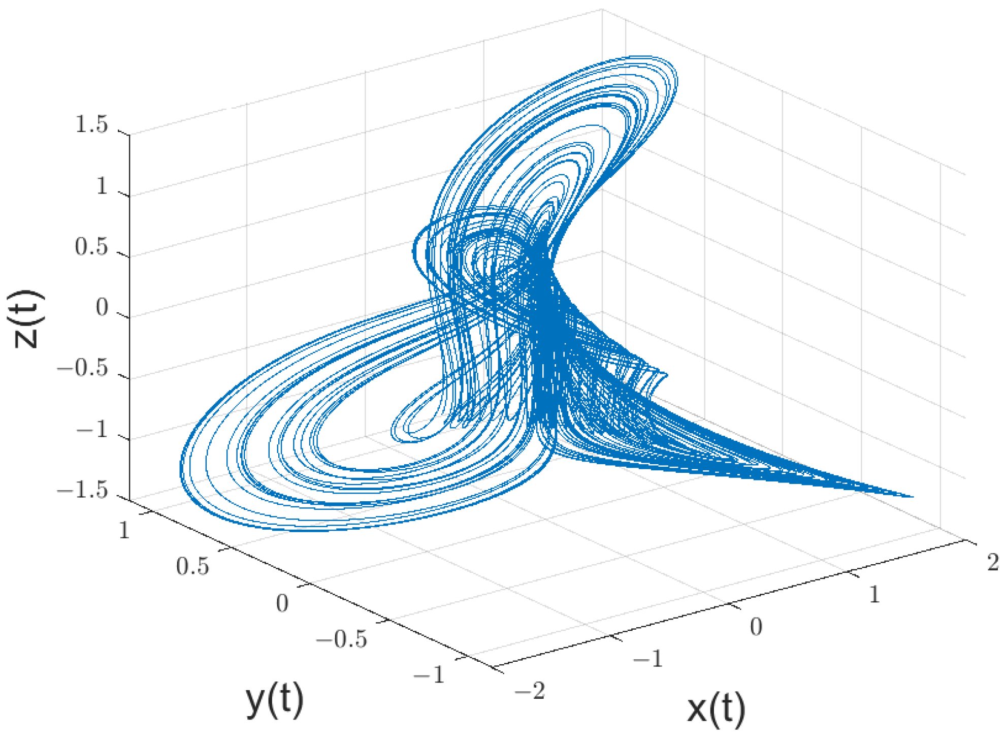
According to the existing studies on chaotic systems of integer order, let , , , , ; take , and . The initial values are taken as . This chaotic system forms a four-wing chaotic attractor as shown in Figure 1.
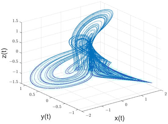
Figure 1.
If , , , , sin, and the starting value of , then a fractional-order multi-wing chaotic system has four wings in its attractor.
2.3. Equilibrium Analysis
Drive force signal G governs system Equation (2), which is non-autonomous. As a result, the left side of system Equation (2) must be set to zero to compute the equilibrium point.
Then, we may determine that, at this moment, the equilibrium points of Equations (1) and (2) are the same and that infinite equilibrium points exist with infinite driving signal G values. Consequently, as indicated in Table 1, they are grouped to obtain five different types of equilibrium points.

Table 1.
Equilibrium points of system Equation (2).
To get the Jacobian matrix, linearize system Equation (2) at the equilibrium points (, , ):
Let ; obtain the corresponding characteristic polynomial as:
where
The eigenvalues of the equilibrium point fulfill if it is stable. According to the Routh–Hurwitz criterion, the equilibrium point is only stable when and . Given the conditions of this paper, we select , and 5, respectively, because the size of G impacts each equilibrium point, and G also affects the system’s ability to identify weak signals. Table 2 displays the equilibrium point’s stability.
Table 2.
Stability of equilibrium points of system Equation (2).
According to Table 2, the equilibrium point belongs to the first class of saddle points, whereas the saddle points , , , and belong to the second class. The first class of saddle points connects the rings of chaotic attractors that were created around the second class of saddle points.
M. S. Tavazoei [42] provides the condition for the system to appear as a locally asymptotically stable equilibrium point, which can be computed to determine the minimal fractional calculus order in which chaos can arise. The results are as follows:
2.4. Dynamic Characteristics under the Influence of Order
The integer-order chaotic system can be considered a specific fractional-order system by the theory of fractional-order calculus. Except for order, the remaining parameters of a fractional-order chaotic system then influence the chaotic system in a way comparable to the law of an integer-order system. As a result, we solely consider how the additional order parameter affects the fractional-order multi-wing chaotic system’s dynamic properties. A bifurcation diagram and SE complexity diagram are used for this. The result is shown in Figure 2:
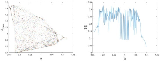
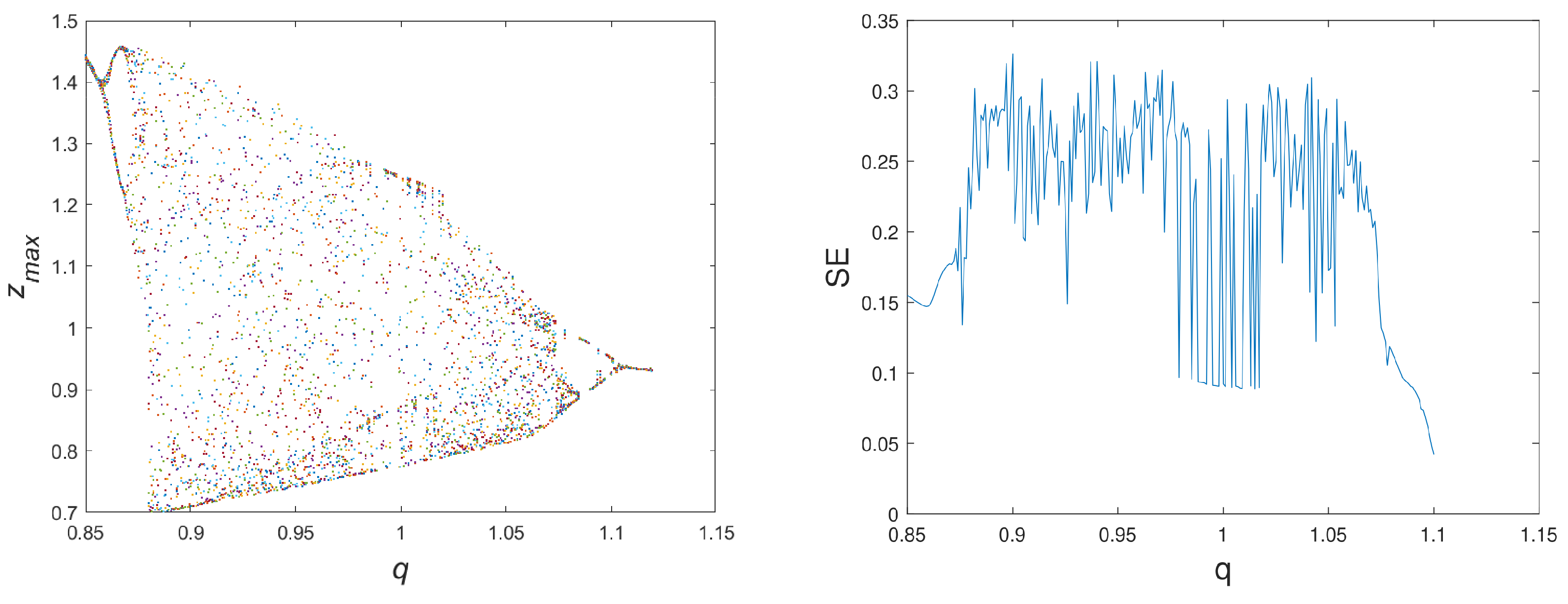
Figure 2.
Bifurcation diagram and SE complexity diagram of the fractional-order multi-wing chaotic system Equation (2) varying with parameter q, where , , , , sin, , and . The value range of q is from 0.85 to 1.15.
The chaotic phenomenon is evident in the range of in Figure 2, which is consistent with the results computed in the preceding section. Furthermore, the chaotic system ceases to be chaotic when the order exceeds , demonstrating how differing fractional-order calculus orders alter the remaining parameters’ control range. Thus, the advantage of the fractional-order chaotic system is demonstrated by the fact that, by altering the order, it can gain a more extensive chaos interval or period window than the integer-order chaotic system’s fixed influence range of each parameter.
Next, taking orders of and as examples, we will compare the influence of G values on the state of chaotic systems at different orders. The results are shown in Figure 3:
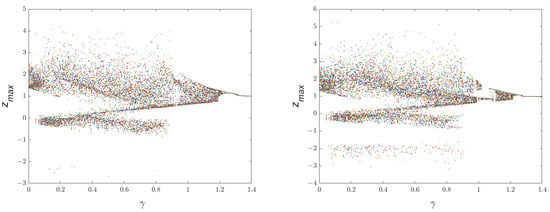
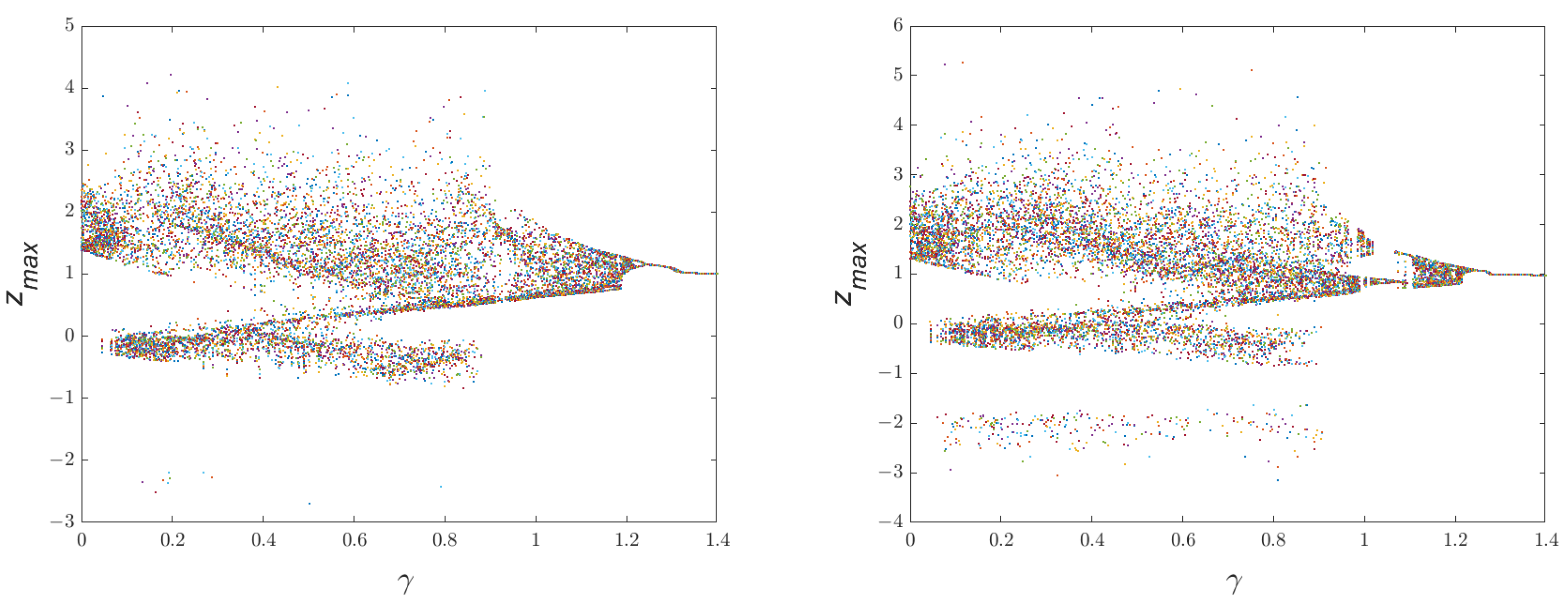
Figure 3.
Bifurcation diagram of the fractional-order multi-wing chaotic system Equation (2) varying with parameter r, where sin, , , , , and in the left panel, in the right panel, and the value range of r is from 0 to 1.4.
From Figure 3, it can be seen that after changing the order value from 1, the length of the chaotic region becomes significantly longer, and the number of occurrences of the period window becomes less. This suggests fewer blind spots for detection and a more comprehensive detection range for weak signal detection with this technique.
3. Weak Signal Detection
The study that is now available indicates that the multi-wing chaotic system Equation (1) has the property of having switchable numbers of wings, which is achieved by varying the driving force G. Consequently, this property of the fractional-order chaotic system remains. Furthermore, this chaotic system possesses the properties of a single-parameter chaotic system with rapid state change, which is compatible with the chaotic system properties required in the field of chaotic weak signal detection. Consequently, it is possible to convert the information of weak signals into fractional-order multi-wing chaotic systems’ dynamical phenomena and thereafter identify the weak signals.
3.1. Amplitudes Detection of Weak Signals
According to the conventional theory of chaotic weak signal detection, adding a weak signal will cause the chaotic system to enter a periodic state. At this time, the chaotic system will undergo chaotic control to revert to its chaotic state, offsetting the added weak signals and the altered control parameter to obtain the signal for measurement. In this process, the chaotic state has a higher noise resistance than the periodic state. Therefore, to circumvent the periodic state’s low robustness to noise, we used the difference between the four-winged and the two-winged chaotic states in this study to detect the weak signals.
First, we considered the case of a single fractional-order chaotic system as a detection system when the equations of the system are:
where is the addition of a mixed signal made up of noise and the signal that has to be measured. A portion of the signal to be measured must be known in advance; g is the same form of the weak signal to be calculated as the drive signal. Considering Gaussian white noise as the noise and a sinusoidal weak signal with a frequency of 1 rad/s, represents the weak signal. The question is how to determine the amplitude of the weak signal at this particular instant. With , , , , and sin, the attractor of Equation (10) is displayed as follows when r is between the critical values of and .
Figure 4 shows that the attractor of the chaotic system Equation (10) will vary if the control parameters are altered by . Consequently, it is possible to determine the variation pattern of control parameters by tracking changes in attractors. The influence of the signal to be tested is similar to altering the control parameters because both the form of G and the signal to be tested are consistent. This allows the attractor’s change to determine the amplitude of the weak signal that needs to be measured. Numerous studies have examined the effects of various noise on chaotic systems [43,44], and fractional-order multi-wing chaotic systems have the inherent ability to withstand noise.
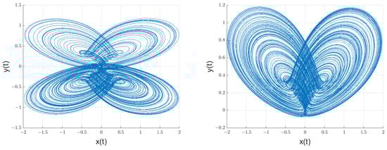
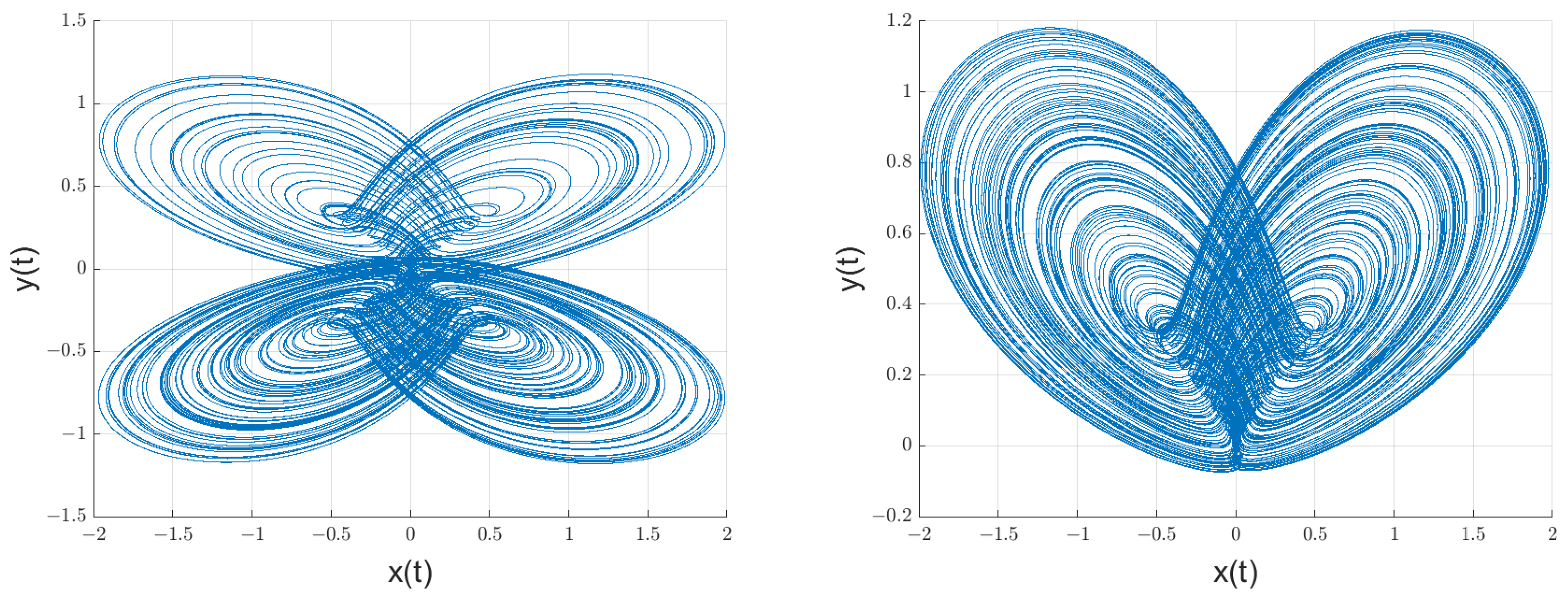
Figure 4.
Using the G-algorithm for the numerical approximation of Riemann–Liouville, the attractor of Equation (10) is projected in the x-y plane, where the parameters are , and the time interval is 0.01; on the left, and on the right.
In terms of the performance of individual chaotic detection, there is no essential difference between fractional-order chaotic systems and integer-order chaotic systems. However, when establishing a chaotic oscillator array, multiple arrays with order differences can be established by changing the fractional order. That is why this paper discusses the use of chaotic oscillator arrays for weak signal detection. It should be noted that fractional-order chaotic systems can use distinct fractional-order systems to form arrays, unlike integer-order systems, which can only modify one parameter. Consequently, the array’s dimensionality has increased. Once the array is established, variations can be used to determine the amplitude information of weak signals. Several arrays can be built to increase precision because this paper’s fractional-order multi-wing chaotic system can display chaotic events in fractional orders between and 1. Here, taking the order equal to as an example, we explain how to use a chaotic oscillator array for detection.
Figure 5 shows that the interval over which the four-wing chaos phenomenon occurs has a few complex windows. When utilizing an array to detect signals instead of a single chaotic oscillator, these windows can prevent errors from occurring. The chaotic array alters due to the addition of various weak signals, as seen in Figure 6.
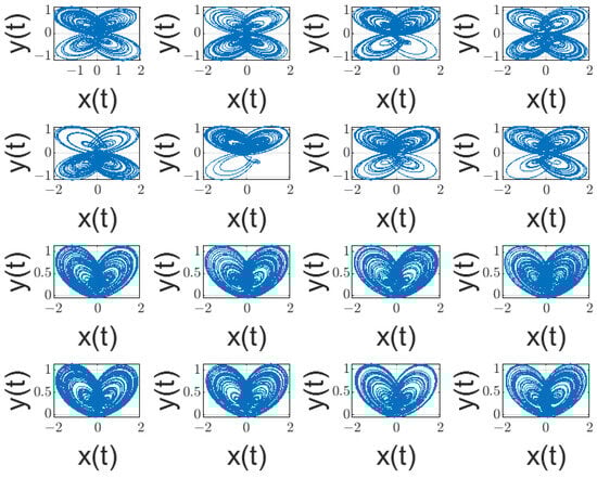
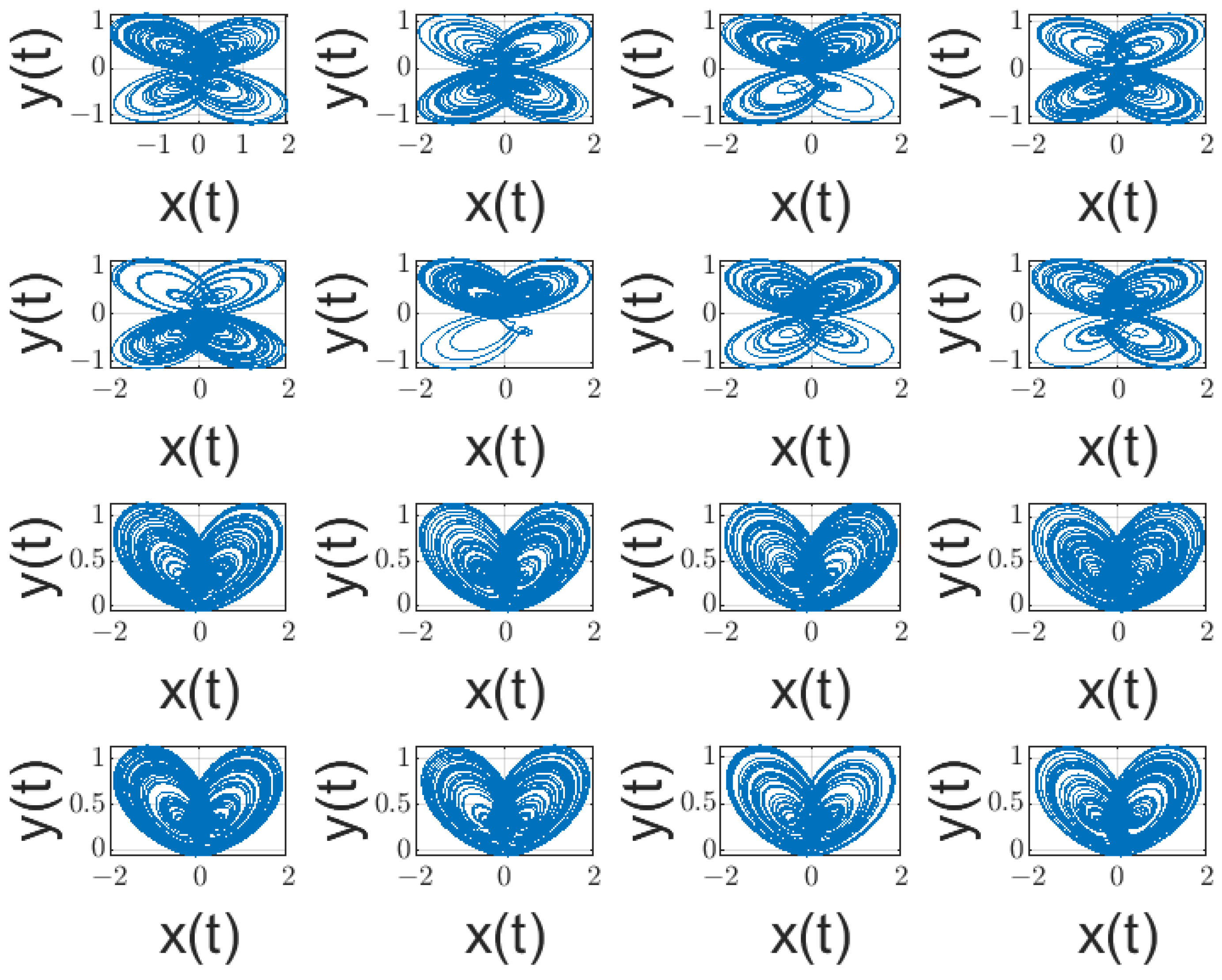
Figure 5.
Chaos oscillator detection array, where the value of r ranges from to , simulation time is 500, and calculation step size is .
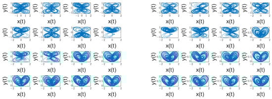
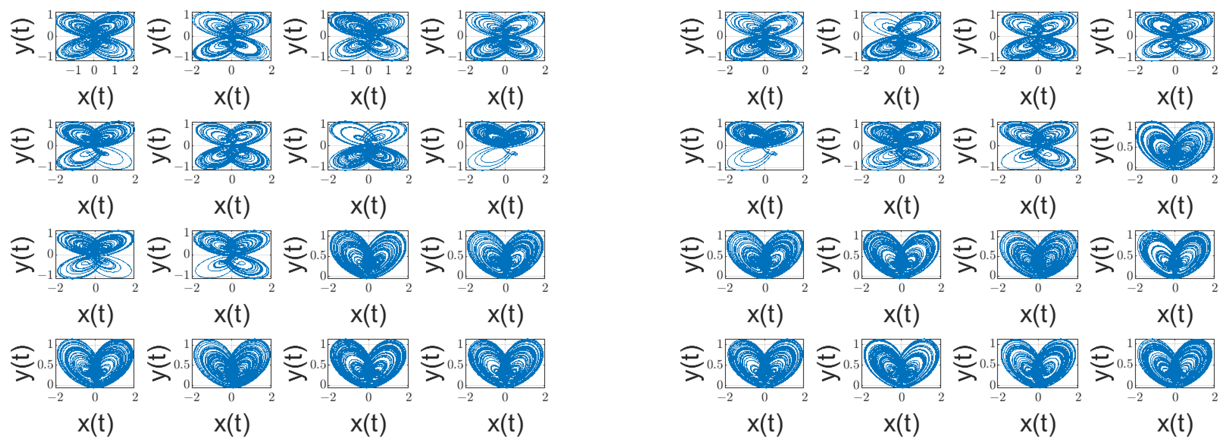
Figure 6.
Chaos oscillator detection array, where the weak signal added on the left is −0.02sin, and on the right it is sin .
Figure 6 illustrates how the addition of weak signals altered the chaotic array’s properties, with the direction of the change varying according to whether the signal was positive or negative. The chaotic array’s wing count will decrease with the addition of a positive weak signal and rise with the addition of a negative weak signal. Thus, in real-world applications, the measured signal’s amplitude can be acquired as long as the chaotic array is located.
From the above analysis, it can be seen that in order to use chaotic arrays to detect weak signals, it is necessary to identify the state of the chaotic array and obtain information on the changes in the chaotic array. If the common Lyapunov exponent method is used, each oscillator needs to be calculated, and the size in this article requires 16 calculations. If the chaotic phase diagram method is used for discrimination, it reduces the calculation time and number of calculations, but there is no universally recognized criterion for qualitative analysis. Therefore, we consider using deep learning image recognition to recognize and distinguish chaotic phase diagrams.
The manuscript introduces deep learning image recognition into the theory of chaotic weak signal detection, which is used to quickly identify information in chaotic arrays. This method has been rare in previous research, and it uses the multi-wing features of the attractor to simultaneously identify the entire array, reducing the judgment time. In addition, the main problem of detecting weak signals with chaos is the need to judge the chaotic state, so currently, commonly used methods make it difficult to design actual signal detection devices. By establishing a chaotic array to transform weak signals into image changes in a chaotic array and then using more mature deep learning image recognition for processing, this design makes the emergence of actual signal detection devices possible.
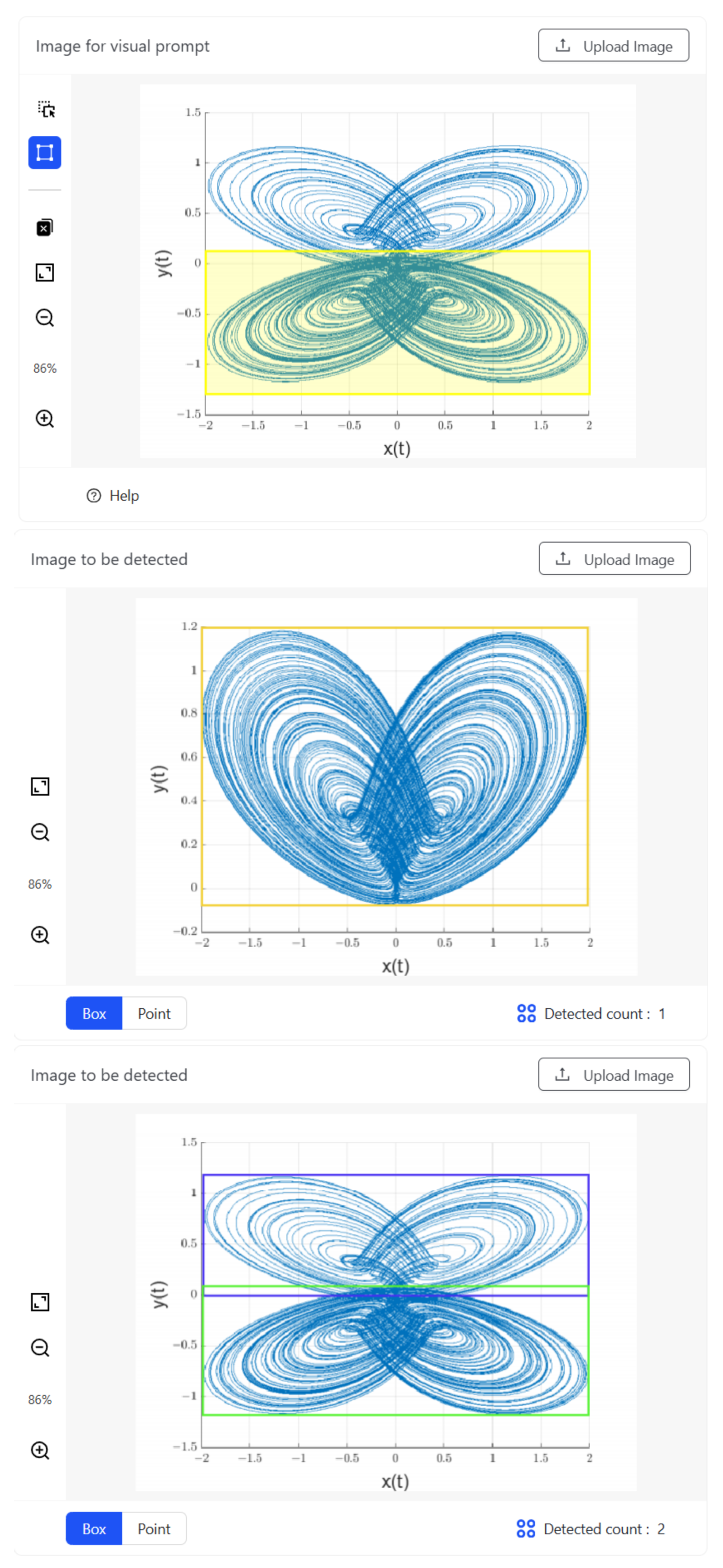
There are many mature models for deep learning image recognition, and the T-Rex2 model is used in this manuscript. It is open-source and can be used on online websites. T-Rex2 is an interactive object counting model designed to first detect and then count any objects. It formulates object counting as an open-set object detection task with the integration of visual prompts. Users can specify the objects of interest by marking points or boxes on a reference image, and T-Rex2 then detects all objects with a similar pattern. Guided by the visual feedback from T-Rex2, users can also interactively refine the counting results by identifying missing or falsely detected objects.
As a result, we may learn the attractor graph based on two wings by using Figure 4 as sample data. Equation (7) presents the findings.
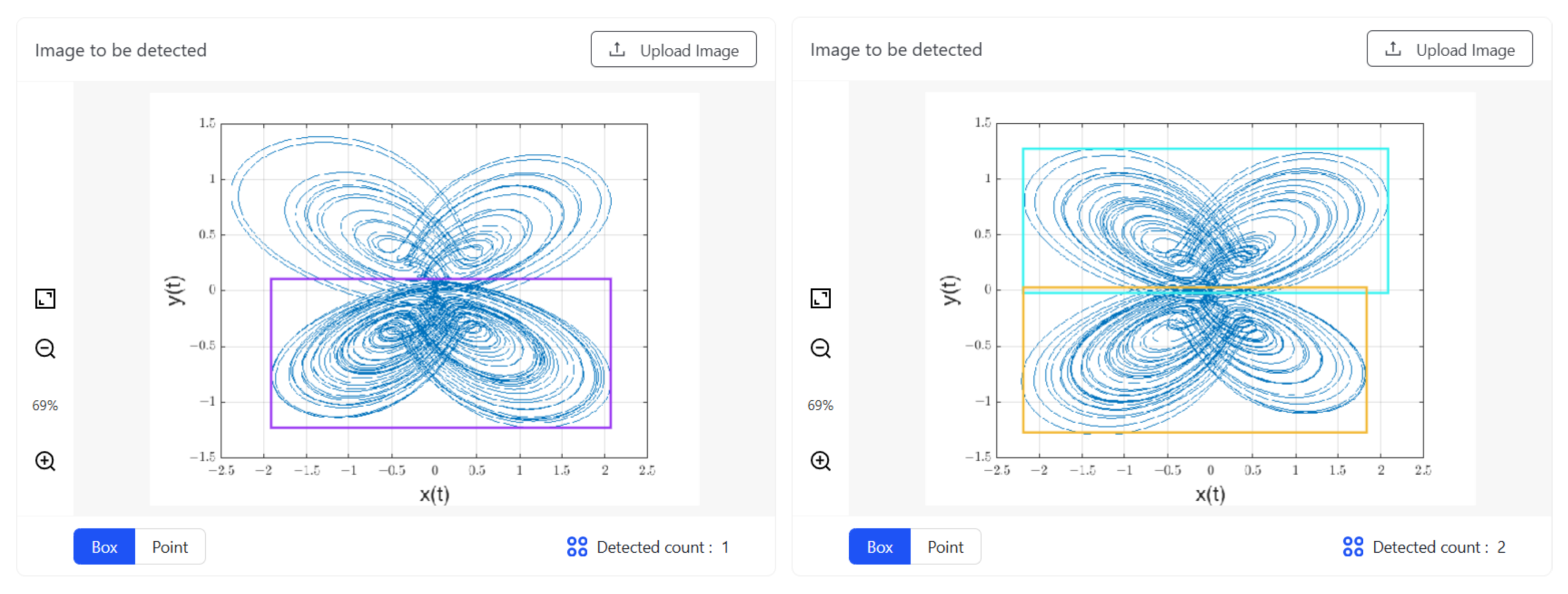
From Figure 7, it can be seen that the deep learning image recognition method can successfully obtain the number of wings of the chaotic attractor based on the number of samples. So the number of wings of the chaotic arrays in Figure 5 and Figure 6 are 21, 23, and 20, respectively. It is possible to determine the precise amplitude of the extra-weak signal by comparing the wing numbers. The actual amplitudes of the weak signals can be determined to be and , respectively, based on the order of magnitude involved in building a chaotic oscillator array.
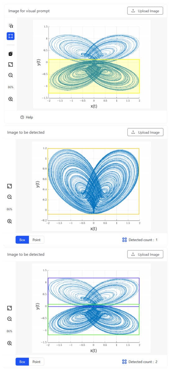
Figure 7.
The yellow solid box indicates that users prompt once on one image. This article selects the double-wing part of the four-wing chaotic attractor. Other different color boxes are automatically annotated by T-Rex2 and display other images with similar object patterns to the prompt image. Using the left half of the four-wing attractor as an example, deep learning image recognition results were able to correctly identify both biplane and four-wing attractors.
Next, we will consider the detection performance of fractional-order multi-wing chaotic systems under the conditions selected for this paper. The lowest detectable signal-to-noise ratio is used to represent the performance, with the specific condition that when the noise is too large and the attractor phase diagram changes to the point where deep learning cannot recognize it, it is considered undetectable. When the noise levels are and , respectively, the results of deep learning image recognition using chaotic attractors are shown in Figure 8.

Figure 8.
The results of chaotic attractors obtained by adding different levels of noise in deep learning image recognition.
So according to the formula, the minimum detectable signal-to-noise ratio of a fractional-order multi-wing chaotic system under the selected conditions is:
3.2. Frequencies Detection of Weak Signals
Currently, frequencies detection can be considered using the sweeping method, but this method is time-consuming and consumes many hardware resources. Therefore, researchers have proposed using the method of chaotic synchronization to detect the frequencies of weak signals. This is because the current research on chaos synchronization has been very in-depth, and many different synchronization methods have been proposed [45,46]. The drive–response method is a very classic chaos synchronization method. The use of the drive–response chaotic system to detect the frequencies of weak signals is based on the principle of using an applied weak signal to change the synchronization error of the chaotic system, and this error is linearly correlated with the applied weak signal. Therefore, the frequencies of the weak signal can be obtained by calculating the frequencies of the error value. The designed driving and controlled response systems are shown in Equations (11) and (12).
The terms , , and in system Equation (12) are nonlinear controllers. Let the synchronization error between system Equation (11) and system Equation (12) be , , and . Then the synchronization error is the difference between Equations (11) and (12). That is, the following synchronization error of fractional-order chaotic systems is obtained:
The synchronization controller is designed as follows:
Bringing system Equation (14) into system Equation (13) yields the final synchronization error, as shown in system Equation (15).
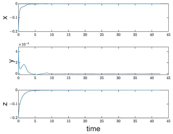
Since the fractional-order order in this paper, the Lyapunov function E is constructed according to the sufficient condition for stability of fractional-order systems [47,48]:
The derivative is then obtained as:
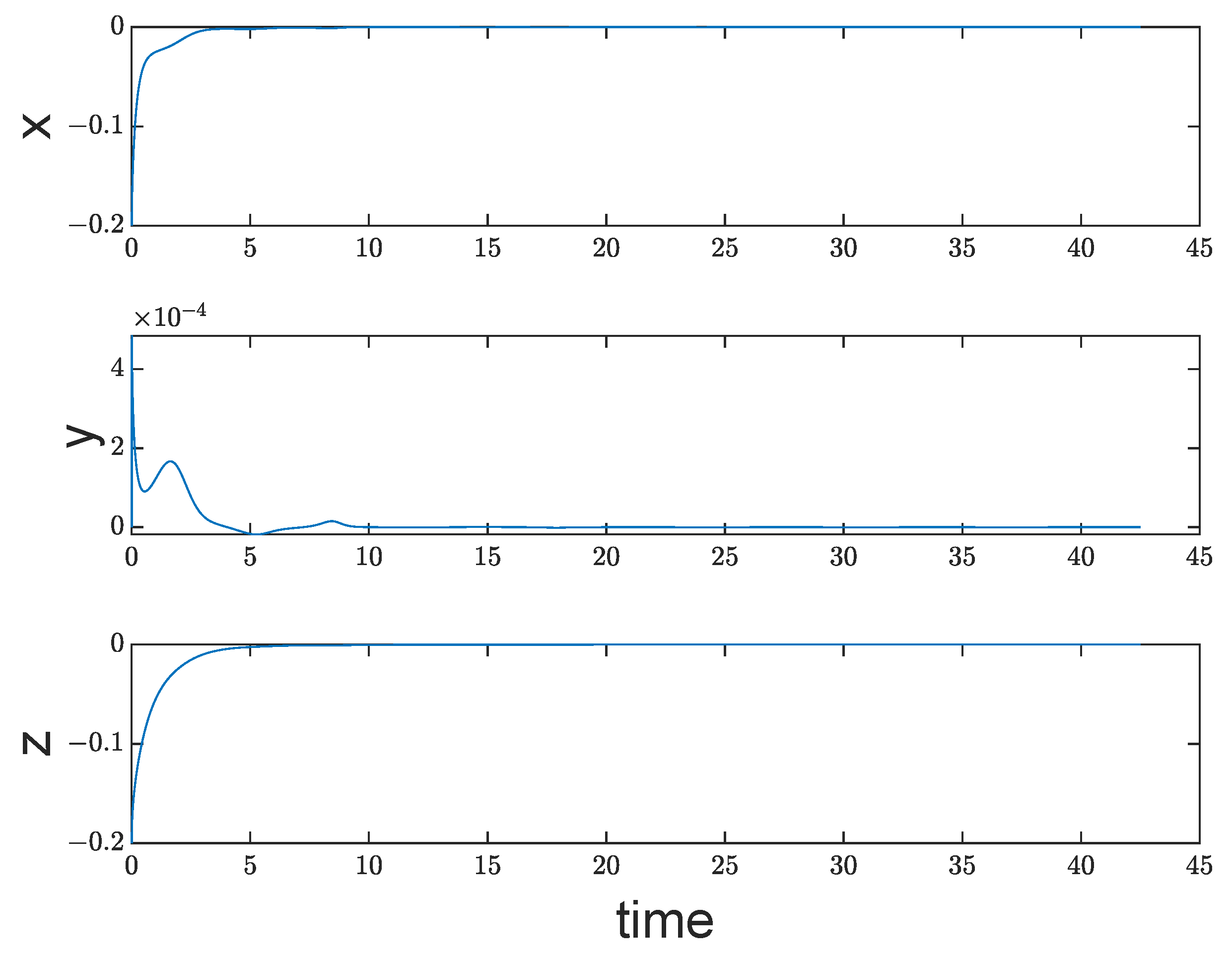
It is obvious that the synchronization error is asymptotically stable; thus, we are able to show that the drive and response systems Equations (11) and (12) are synchronized, as shown in Figure 9.
Therefore, synchronization errors can be used to observe changes in the drive–response system when detecting the signal’s frequencies. For instance, the equation for driving the system becomes as follows when a mixed signal, , is added to the third component in system Equation (11):
Thus, will enter the chaotic system’s iteration in system (16), and will not change the chaotic system’s dynamic properties. On the other hand, if has the same form as G, then altering the system’s parameters equals modifying the chaotic system’s dynamic properties. As seen in Figure 10, this will modify the chaotic synchronization system’s synchronization error.
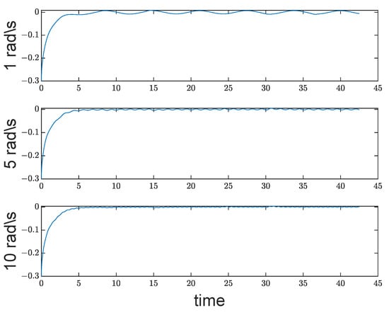
Figure 10.
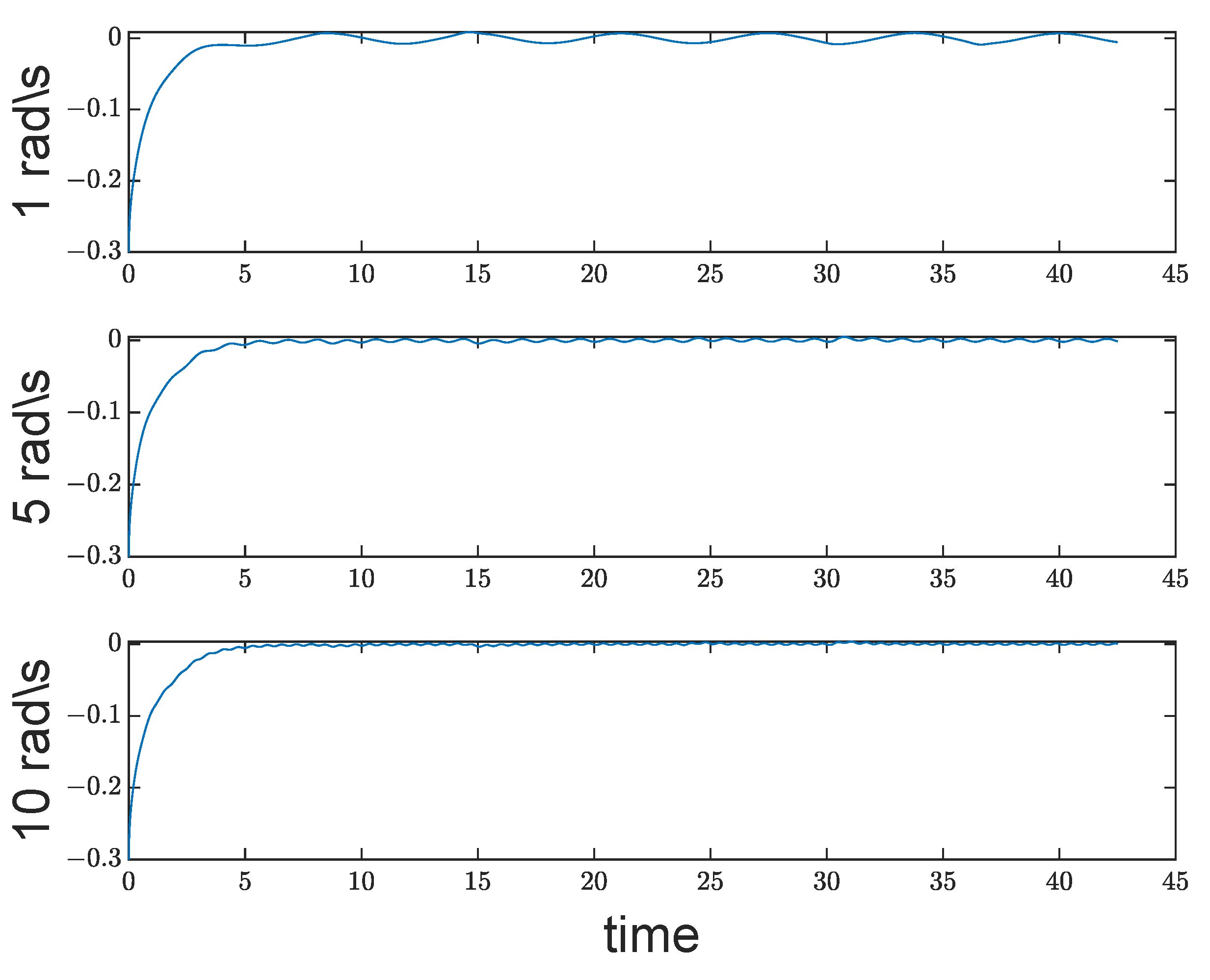
After adding of different frequencies to system Equation (16), the error between the selected state variables z in the figure show the synchronization error of the chaotic synchronization system, where sin, where is 1, 5, and 10 rad/s.
Figure 10 illustrates this point. While the chaotic system is stable, varying will result in varying synchronization errors, and the frequencies of fluctuations in synchronization errors is equal to that of . Thus, it is possible to determine the frequencies of by computing the frequencies of synchronization mistakes. Additionally, a weak signal frequencies was found. The frequencies inside the synchronization error can be obtained in various ways. Schmidt [49] proposed the MUSIC algorithm, which is used in this paper. This algorithm can assess the signal’s frequencies and successfully withstand noise. The following are the primary steps:
1. Use N data points stabilized by the synchronization error, then extract data points from them as the sample matrix.
2. Find the covariance matrix of the constructed sample. .
3. Perform eigenvalue decomposition of the covariance matrix R. The eigenvalues are arranged from small to large, and the first m corresponding eigenvectors are taken to construct the signal eigenmatrix . The rest are used to construct the noise characteristic matrix .
4. Using the frequencies estimation formula, , where , the maximum value of calculated is the frequencies of the synchronization error.
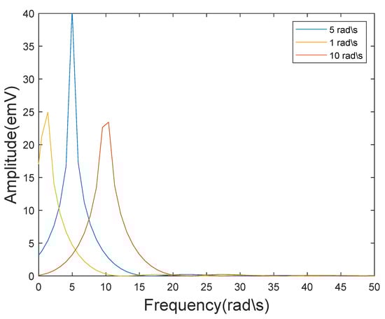
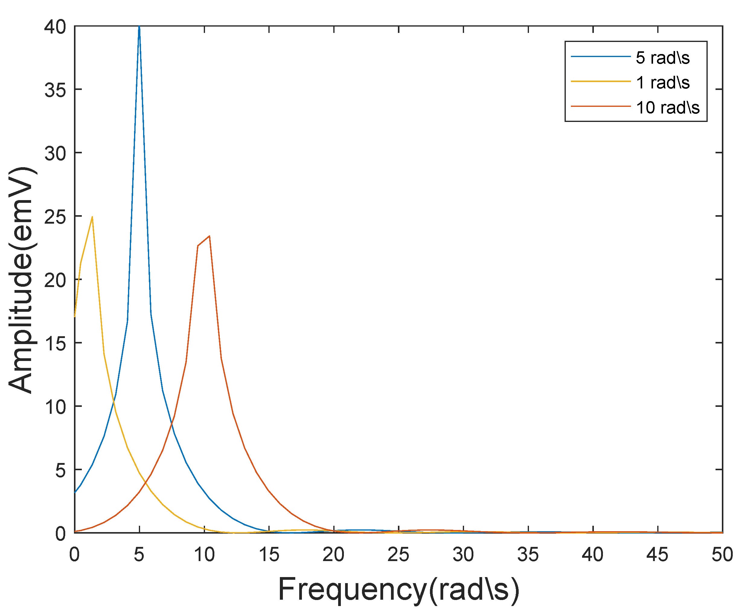
Figure 11.
The result graph of frequencies estimation using the MUSIC algorithm for the stable synchronization error shows three peaks around 1, 5, and 10 rad/s.
From Figure 11, it can be seen that the three peaks in the resulting graph are around 1, 5, and 10 rad/s, which is consistent with the frequencies of the weak signal we input. This result indicates that using a synchronous fractional-order multi-wing chaotic system to detect the frequencies of weak signals is feasible.
4. Conclusions
This paper addresses the potential application of fractional-order multi-wing chaotic systems for weak signal detection. First, the impact of order in fractional calculus on the dynamic properties of chaotic systems is examined. Based on the findings, a fractional-order multi-wing chaotic system is chosen as the weak signal detection system. In the case of amplitude detection, the various features of chaotic array detection and single detection oscillators are examined independently. Suppose that frequencies detection of weak signals is required. In that case, a fractional-order multi-wing chaotic system with drive–response synchronization is devised to detect the frequencies of the measured signal through changes in the synchronization error. When processing data, the MUSIC technique measures the synchronization error and subsequently estimates the frequencies of weak signals. Deep learning image recognition is used to process the number of wings of chaotic arrays.
The novelty of the work in this paper consists of the following: First, the creation of chaotic oscillator detection arrays highlights the advantages of fractional-order chaotic systems. Secondly, using the difference between four-winged chaotic states and double-winged chaotic states for detection makes both states resistant to noise. Finally, the states of the chaotic array are identified using deep learning images: a method that significantly reduces the judgment time compared to the usual Lyapunov method.
This paper still requires some prior knowledge to identify weak signals. Furthermore, this paper’s correctness could still be enhanced. Therefore, the main problem of chaotic weak signal detection theory remains how to detect the frequencies and amplitude of weak signals simultaneously. The primary issue is that high accuracy increases the approximate calculation error of fractional calculus and complicates the construction of chaotic arrays and synchronization. Consequently, the engineering implementation of the suggested signal detection technique will be the main focus of future research.
Author Contributions
Conceptualization, H.M. and Z.Y.; Data curation, X.W.; Formal analysis, H.M.; Funding acquisition, C.G.; Investigation, H.M.; Methodology, H.M.; Project administration, Z.Y.; Resources, Y.F.; Software, H.M.; Supervision, Y.F., C.G. and Z.Y.; Validation, H.M., Y.F. and Z.Y.; Visualization, Z.Y.; Writing—original draft, H.M.; Writing—review and editing, X.W. All authors have read and agreed to the published version of the manuscript.
Funding
This research was funded by grants from the Key Science and Technology Research Projects in Jilin Province (grant No. 20160204020GX) and the Jilin Province Science and Technology Development Plan Project (grant No. 20190201135JC).
Institutional Review Board Statement
Not applicable.
Informed Consent Statement
Not applicable.
Data Availability Statement
The raw data supporting the conclusions of this article will be made available by the authors on request.
Conflicts of Interest
The authors declare no conflicts of interest.
Abbreviations
The following abbreviations are used in this manuscript:
| MUSIC | Multi-signal classification |
References
- Birx, D.L.; Pipenberg, S.J. Chaotic oscillators and complex mapping feed forward networks(CMFFNs) for signal detection in noisy environments. In Proceedings of the [Proceedings 1992] IJCNN International Joint Conference on Neural Networks, Baltimore, MD, USA, 7–11 June 1992. [Google Scholar]
- Wang, G.Y.; He, S. Quantitative study on detection and estimation of weak signals by using chaotic duffifing oscillators. IEEE Trans. Circuits Syst. I 2003, 50, 945–953. [Google Scholar] [CrossRef]
- Wang, Q.B.; Yang, Y.J.; Zhang, X. Weak signal detection based on Mathieu-Duffing oscillator with time-delay feedback and multiplicative noise. Chaos Solitons Fractals 2020, 137, 109832. [Google Scholar] [CrossRef]
- Jiao, S.B.; Jiang, W.; Lei, S.; Huang, W.C.; Zhang, Q. Research on detection method of multi-frequency weak signal based on stochastic resonance and chaos characteristics of Duffing system. Chin. J. Phys. 2020, 64, 333–347. [Google Scholar]
- Zhao, Z.H.; Yang, S. Application of van der Pol-Duffing oscillator in weak signal detection. Comput. Electr. Eng. 2015, 41, 1–8. [Google Scholar]
- Li, Q.Y.; Shi, S. Research on weak signal detection method based on duffing oscillator in narrowband noise. In Proceedings of the Artificial Intelligence for Communications and Networks: Second EAI International Conference, Virtual Event, 19–20 December 2020. [Google Scholar]
- Akilli, M.; Yilmaz, N.; Gediz Akdeniz, K. Automated system for weak periodic signal detection based on Duffing oscillator. IET Signal Process. 2020, 14, 710–716. [Google Scholar] [CrossRef]
- Li, C.S.; Qu, L.S. Applications of chaotic oscillator in machinery fault diagnosis. Mech. Syst. Signal Process. 2007, 21, 257–269. [Google Scholar] [CrossRef]
- Chen, H.Y.; Lv, J.T.; Zhang, S.Q.; Zhang, L.G.; Li, J. Chaos weak signal detecting algorithm and its application in the ultrasonic Doppler bloodstream speed measuring. J. Phys. Conf. Ser. 2005, 13, 320. [Google Scholar] [CrossRef]
- Hu, G.; Wang, K.J.; Liu, L.L. Detection Line Spectrum of Ship Radiated Noise Based on a New 3D Chaotic System. Sensors 2021, 21, 1610. [Google Scholar] [CrossRef] [PubMed]
- Xiong, L.; Qi, L.W.; Teng, S.F.; Wang, Q.S.; Wang, L.; Zhang, X.G. A simplest Lorenz-like chaotic circuit and its applications in secure communication and weak signal detection. EPJ-Spec. Top. 2021, 230, 1933–1944. [Google Scholar] [CrossRef]
- Shi, M.; Jin, C.L. Applying Improved Chaos System to Weak Signal Detection. In Proceedings of the 2015 International Industrial Informatics and Computer Engineering Conference, Xi’an, China, 10–11 January 2015. [Google Scholar]
- Li, G.Z.; Tan, N.L.; Su, S.Q.; Zhang, C. Unknown frequency weak signal detection based on Lorenz chaotic synchronization system. J. Vib. Shock 2019, 38, 155–161. [Google Scholar]
- Li, G.Z.; Zhang, B. A Novel Weak Signal Detection Method via Chaotic Synchronization Using Chua’s Circuit. IEEE Trans. Ind. Electron. 2017, 64, 2255–2265. [Google Scholar] [CrossRef]
- Li, Y.; Li, F.G.; Lyu, S.X.; Xu, M.; Wang, S.Y. Blind extraction of ECG signals based on similarity in the phase space. Chaos Solitons Fractals 2021, 147, 110950. [Google Scholar] [CrossRef]
- Li, S.Y.; Lin, Y.C.; Tam, L.M. A smart detection technology for personal ECG monitoring via chaos-based data mapping strategy. Multimed. Tools Appl. 2021, 80, 6397–6412. [Google Scholar] [CrossRef]
- Yin, C.; Jiang, S.B.; Zhang, Y.N. A Photoacoustic Spectrum Detection System Based on Chaos Detection of Weak Signal. In Proceedings of the 2021 IEEE 5th Advanced Information Technology, Electronic and Automation Control Conference, Chongqing, China, 12–14 March 2021. [Google Scholar]
- Soong, C.Y.; Huang, W.T.; Lin, F.P.; Tzeng, P.Y. Controlling chaos with weak periodic signals optimized by a genetic algorithm. Phys. Rev. E 2004, 70, 016211. [Google Scholar] [CrossRef] [PubMed]
- Yang, Y.; Huang, L.L.; Xiang, J.H.; Bao, H.; Li, H.Z. Generating multi-wing hidden attractors with only stable node-foci via non-autonomous approach. Phys. Scr. 2021, 96, 125220. [Google Scholar] [CrossRef]
- Wu, Q.J.; Hong, Q.H.; Liu, X.Y.; Wang, X.P.; Zeng, Z.G. A novel amplitude control method for constructing nested hidden multi-butterfly and multiscroll chaotic attractors. Chaos Solitons Fractals 2020, 134, 109727. [Google Scholar] [CrossRef]
- Sahoo, S.; Roy, B.K. Design of multi-wing chaotic systems with higher largest Lyapunov exponent. Chaos Solitons Fractals 2022, 157, 111926. [Google Scholar] [CrossRef]
- Peng, X.N.; Zeng, Y.C. A simple method for generating mirror symmetry composite multiscroll chaotic attractors. Int. J. Bifurc. Chaos 2020, 30, 2050220. [Google Scholar] [CrossRef]
- Yan, D.W.; Ji’e, M.; Wang, L.D.; Duan, S.K.; Du, X.Y. Generating novel multi-scroll chaotic attractors via fractal transformation. Nonlinear Dyn. 2022, 107, 3919–3944. [Google Scholar] [CrossRef]
- Hong, Q.H.; Wu, Q.J.; Wang, X.P.; Zeng, Z.G. Novel Nonlinear Function Shift Method for Generating Multiscroll Attractors Using Memristor-Based Control Circuit. IEEE Trans. Very Large Scale Integr. (VLSI) Syst. 2019, 27, 1174–1185. [Google Scholar] [CrossRef]
- Li, W.J.; Li, P.; Jia, M.M. Chaos control and chaos synchronization of a multi-wing chaotic system and its application in multi-frequency weak signal detection. AIP Adv. 2021, 11, 095003. [Google Scholar] [CrossRef]
- Yan, S.H.; Sun, X.; Wang, Q.Y.; Ren, Y.; Shi, W.L.; Wang, E. A novel double-wing chaotic system with infinite equilibria and coexisting rotating attractors: Application to weak signal detection. Phys. Scr. 2021, 96, 125216. [Google Scholar] [CrossRef]
- Hammouch, Z.; Yavuz, M.; Ozdemir, N. Numerical Solutions and Synchronization of a Variable-Order Fractional Chaotic System. Math. Model. Numer. Simul. Appl. 2021, 1, 11–23. [Google Scholar] [CrossRef]
- Chen, L.P.; Yin, H.; Huang, T.W.; Yuan, L.G.; Zheng, S.; Yin, L.S. Chaos in fractional-order discrete neural networks with application to image encryption. Neural Netw. 2020, 125, 174–184. [Google Scholar] [CrossRef] [PubMed]
- Baleanu, D.; Zibaei, S.; Namjoo, M.; Jajarmi, A. A nonstandard finite difference scheme for the modeling and nonidentical synchronization of a novel fractional chaotic system. Adv. Differ. Equ. 2021, 2021, 308. [Google Scholar] [CrossRef]
- Wang, S.J.; He, S.B.; Yousefpour, A.; Jahanshahi, H.; Repnik, R.; Perc, M. Chaos and complexity in a fractional-order financial system with time delays. Chaos Solitons Fractals 2020, 131, 109521. [Google Scholar] [CrossRef]
- Sayed, S.; Amir, A.; Emile Franc Doungmo Goufo. Investigation of complex behaviour of fractal fractional chaotic attractor with mittag-leffler Kernel. Chaos Solitons Fractals 2021, 152, 111332. [Google Scholar]
- He, Y.Z.; Fu, Y.X.; Qiao, Z.J.; Kang, Y.M. Chaotic resonance in a fractional-order oscillator system with application to mechanical fault diagnosis. Chaos Solitons Fractals 2021, 142, 110536. [Google Scholar] [CrossRef]
- Huang, P.F.; Chai, Y.; Chen, X.L. Multiple dynamics analysis of Lorenz-family systems and the application in signal detection. Chaos Solitons Fractals 2022, 156, 111797. [Google Scholar] [CrossRef]
- Li, G.H.; Xie, R.T.; Yang, H. Detection method of ship-radiated noise based on fractional-order dual coupling oscillator. Nonlinear Dyn. 2024, 112, 2091–2118. [Google Scholar] [CrossRef]
- Qiao, Z.J.; He, Y.B.; Liao, C.R.; Zhu, R.H. Noise-boosted weak signal detection in fractional nonlinear systems enhanced by increasing potential-well width and its application to mechanical fault diagnosis. Chaos Solitons Fractals 2023, 175, 113960. [Google Scholar] [CrossRef]
- Dong, K.F.; Xu, K.; Zhou, Y.Y.; Zuo, C.; Wang, L.M.; Zhang, C.; Jin, F.; Song, J.; Mo, W.; Hui, Y. A memristor-based chaotic oscillator for weak signal detection and its circuitry realization. Nonlinear Dyn. 2022, 109, 2129–2141. [Google Scholar] [CrossRef]
- Zhang, S.; Zeng, Y.C.; Li, Z.J. One to four-wing chaotic attractors coined from a novel 3D fractional-order chaotic system with complex dynamics. Chin. J. Phys. 2018, 56, 793–806. [Google Scholar] [CrossRef]
- Cai, H.; Sun, J.Y.; Gao, Z.B.; Zhang, H. A novel multi-wing chaotic system with FPGA implementation and application in image encryption. J.-Real-Time Image Process. 2022, 19, 775–790. [Google Scholar] [CrossRef]
- Wang, C.H. Dynamic Behavior Analysis and Robust Synchronization of a Novel Fractional-Order Chaotic System with Multiwing Attractors. J. Mathematics. 2021, 2021, 6684906. [Google Scholar] [CrossRef]
- Zhang, S.; Zeng, Y.C.; Li, J.Z. A Novel Four-Dimensional No-Equilibrium Hyper-Chaotic System With Grid Multiwing Hyper-Chaotic Hidden Attractors. J. Comput. Nonlinear Dynam. 2018, 13, 090908. [Google Scholar] [CrossRef]
- Sahoo, S.; Roy, B.K. A new multi-wing chaotic attractor with unusual variation in the number of wings. Chaos Solitons Fractals 2022, 164, 112598. [Google Scholar] [CrossRef]
- Tavazoei, M.S.; Haeri, M. A necessary condition for double scroll attractor existence in fractional-order systems. Phys. Lett. A 2007, 367, 102–113. [Google Scholar] [CrossRef]
- Nie, C.Y.; Wang, Z.W. Application of Chaos in Weak Signal Detection. In Proceedings of the 2011 Third International Conference on Measuring Technology and Mechatronics Automation, Shanghai, China, 6–7 January 2011. [Google Scholar]
- Faber, J.; Bozovic, D. Noise-induced chaos and signal detection by the nonisochronous Hopf oscillator. Chaos 2019, 29, 043132. [Google Scholar] [CrossRef] [PubMed]
- Wang, S.F. Finite-time synchronization of fractional multi-wing chaotic system. Phys. Scr. 2023, 98, 115224. [Google Scholar] [CrossRef]
- Kumar, V.; Heiland, J.; Benner, P. Projective lag quasi-synchronization of coupled systems with mixed delays and parameter mismatch: A unified theory. Neural Comput. Applic. 2023, 35, 23649–23665. [Google Scholar] [CrossRef]
- Matignon, D. Stability Results For Fractional Differential Equations With Applications To Control Processing. Comput. Eng. Syst. Appl. 1997, 2, 963–968. [Google Scholar]
- Hu, J.B.; Han, Y.; Zhao, L.D. A novel stablility theorem for fractional systems and its applying in synchronizing fractional chaotic system based on back-stepping approach. Acta Phys. Sin. 2009, 58, 2235–2239. [Google Scholar]
- Schmidt, R. Multiple emitter location and signal parameter estimation. IEEE Trans. Antennas Propag. 1986, 34, 276–280. [Google Scholar] [CrossRef]
Disclaimer/Publisher’s Note: The statements, opinions and data contained in all publications are solely those of the individual author(s) and contributor(s) and not of MDPI and/or the editor(s). MDPI and/or the editor(s) disclaim responsibility for any injury to people or property resulting from any ideas, methods, instructions or products referred to in the content. |
© 2024 by the authors. Licensee MDPI, Basel, Switzerland. This article is an open access article distributed under the terms and conditions of the Creative Commons Attribution (CC BY) license (https://creativecommons.org/licenses/by/4.0/).