Article

Fish-Tail Structured Fractal Monopole Printed Antenna with Dual Broadband Characteristics for Sub–6GHz 5G and X–Band Radar Applications

by
Guntamukkala Yaminisasi
1,
Pokkunuri Pardhasaradhi
1,
Nagandla Prasad
2,
Boddapati Taraka Phani Madhav
1,
Abeer D. Algarni
3,*,
Sudipta Das
4,* and
Mohammed El Ghzaoui
5
1
Department of Electronics and Communication Engineering, Koneru Lakshmaiah Education Foundation, Vaddeswaram, Guntur 522502, Andra Pradesh, India
2
Department of Electronics and Communication Engineering, GMR Institute of Technology, Razam 532127, Andra Pradesh, India
3
Department of Information Technology, College of Computer and Information Sciences, Princess Nourah bint Abdulrahman University, P.O. Box 84428, Riyadh 11671, Saudi Arabia
4
Department of Electronics and Communication Engineering, IMPS College of Engineering and Technology, Malda 732103, West Bengal, India
5
Faculty of Sciences Dhar El Mahraz-Fes, Sidi Mohamed Ben Abdellah University, Fes P.O. Box 1796, Morocco
*
Authors to whom correspondence should be addressed.
Fractal Fract. 2025, 9(1), 29; https://doi.org/10.3390/fractalfract9010029
Submission received: 17 November 2024 / Revised: 3 January 2025 / Accepted: 4 January 2025 / Published: 7 January 2025

Abstract

:
This article presents a printed antenna, designed with a fractal-shaped patch with fish-tail structured outer edges, a tapered feedline, and a rectangular notch-based defected partial ground structure (DPGS). The presented design has been printed on a FR-4 substrate, which has a dielectric constant of 4.4 and a loss tangent of 0.035. The overall dimension of the proposed antenna is 24 × 40 × 1.6 mm3. The proposed fractal antenna achieved dual broad-band functionality by maintaining the compact size of the radiator. The designed fractal radiator can operate at three distinct resonant frequencies (3.22, 7.64, and 9.41 GHz), covering two distinct frequency bands, extending from 2.5 to 4.2 GHz and 7 to 9.8 GHz. A thorough parametric analysis has been carried out using CST Studio suite 2019 licensed version to achieve better performance in terms of S11 (dB), radiation efficiency, and gain over the operating frequency range. The operating bands fall within the S, C, and X bands to support sub-6GHz 5G and Radar applications at the microwave frequency range.

1. Introduction

There is a growing need for portable terminals that can operate in a variety of frequency bands due to the rapid advancement of wireless communication technologies. In the restricted space of mobile terminals, it is still a significant challenge to incorporate many internal antennas. Due to their capacity to operate in multiple bands, multiband antennas are promising candidates for mobile terminals that offer a variety of wireless communication services. Researchers have undertaken numerous noteworthy endeavours over the past few years to create multiband antennas for a variety of microwave frequency applications. The Institute of Electrical and Electronics Engineers (IEEE) has designated different microwave bands, such as L, S, C, and X-bands, etc., to support a variety of wireless communication applications, such as satellite communications, radar systems, certain Wi-Fi devices, certain surveillance systems, and terrestrial broadband communication. As far as wireless communication systems are concerned, an antenna is important for establishing efficient communication links. For applications such as spaceborne systems and radar or satellite systems, microstrip antennas are the most suitable due to their small size, lightweight, cost-effectiveness, and ease of fabrication.
Fractal shapes are rapidly becoming an intriguing subject in the field of electromagnetic (EM) technology. Conventional patch antennas can reduce their overall size by increasing the electrical length through the use of fractal geometries. Additionally, the self-similarity of fractal shapes makes them exceptional for achieving multiband or broadband capabilities. In the field of electromagnetic (EM) technology, fractal shapes are receiving a high level of interest in antenna miniaturization applications. Fractal geometries can reduce the overall size of resonant structures by increasing the electrical length of conventional antennas. An array of small elements can have various benefits, such as lowering mutual coupling, allowing little space between elements, and higher angular stability. The benefits mentioned above have led to a significant interest in fractal antenna studies today. Using advanced design methods, such as arranging slits and slots and adding defective ground structure (DGS) to the fractal design, can make the fractal antenna work better by keeping the gain constant, blocking unwanted radiation, matching the impedance, being small, and having a high radiation efficiency.
Over the last few decades, many researchers have proposed various fractal antenna configurations to support various categories of wireless applications, including 5G systems. Werner et al. [1] reported that fractal-shaped designs can enhance an antenna’s bandwidth. In [2], the authors reported a fractal-based spherical antenna geometry for mm-wave applications. Furthermore, the authors proposed a printed leaf-shaped [3] antenna for improved performance in ground-penetrating radar (GPR) applications. In ref. [4], a fork-shaped antenna for WLAN/Wi-MAX applications was proposed. The cauliflower-shaped antenna exhibited better performance for multi-band operation [5]. Yadav et al. [6] built and simulated a parasitic patch with trident shape on ground plane for S/C/X applications. A 5G rotating frame radiator with a rotated square fractal structure as a patch fed by a microstrip feed line was proposed in ref. [7]. Numerous innovative fractal geometries, including Vicsek [8], Sierpinski hexagonal shape [9], hexagonal Koch [10], pentagonal shape [11], butterfly-wing shape [12], and the plus-shaped fractal-like elements [13], etc., were proposed and examined with different ground structures for a range of antenna performance metrics, including gain, decent reflection coefficient, radiation efficiency, and reduction of interference of undesired radiation pattern. Furthermore, the authors reported a Hilbert curve fractal antenna for numerous wireless systems [14], a Cantor fractal radiator for IOT applications [15], and vehicular applications [16]. For UWB applications, different fractal geometries were used, including the circular fractals [17,18]. Furthermore, Cantor sets fractal [19] and slot antenna [20] helps in enhancing the performance of the antenna. Refs. [21,22,23,24] show the compact novel fractal monopole antennas with better performance, but they lack the detailed analysis of radiation patterns and low concentration on multi-band operation. Patel et al. [25] proposed an SRR-based, crossed-flower-shaped fractal antenna that utilizes a defective ground structure to achieve dual bands for satellite and 5G communications. The crossed flower-shaped antenna operates within the frequency ranges of 4.01–4.82 and 7.6–7.94 with peak gains of 1.5 and 2.05, respectively. Palanisamy et al. [26] proposed a fractal antenna for both S and C bands with a compact size of 27.84 × 23.25 mm2. To achieve a broad bandwidth of 4.2 GHz with 6.8 dBi of peak gain in the X-band, Rabie et al. [27] have proposed another fractal antenna with a compact size of 19.7 × 23 mm2. A high gain is achieved using a Koch fractal FSS-based antenna that is proposed by Atul et al. [28] for S, C, sub-6 GHz, and X-band applications with a size of 35.94 × 38.97 mm2. Parchin et al. [29] proposed a dual-band antenna using a partial ground structure for RFID applications. In this research work, we propose a unique circular fractal monopole antenna with a defective ground structure that resonates at three distinct resonant frequencies (3.22, 7.64, and 9.41 GHz) encompassing two unique frequency bands, extending from 2.5 to 4.2 GHz and 7 to 9.8 GHz. The operating bands fall within the S, C, and X bands to support sub-6GHz 5G and radar applications at the microwave frequency range.
The main salient features of this proposed fractal radiator are as follows
  • It provides dual broad bands with triple distinct resonant frequencies in the S, C, and X bands.
  • Its structure is a novel one with a compact size.
  • The antenna is validated with an equivalent circuit diagram.
  • It performs with acceptable radiation efficiency at the corresponding resonant frequencies.
  • The antenna prototype is verified with measurements.
  • The proposed fractal antenna achieved dual broad-band functionality by maintaining a compact volume (24 mm × 40 mm × 1.6 mm).

2. Design Framework

Figure 1 shows the design framework of the propounded fractal radiator in the form of a flowchart representation. The design framework model outlines the entire design execution of the prescribed antenna, starting with the design goal, materials selection, design specifications, design evolution steps, simulation analysis, equivalent circuit modeling, prototype realization, and experimental validation. A vector network analyzer is used to experimentally test the S-parameter, while radiation parameters are measured in an anechoic chamber by placing a reference antenna and the antenna under test.

3. Prescribed Antenna Configuration

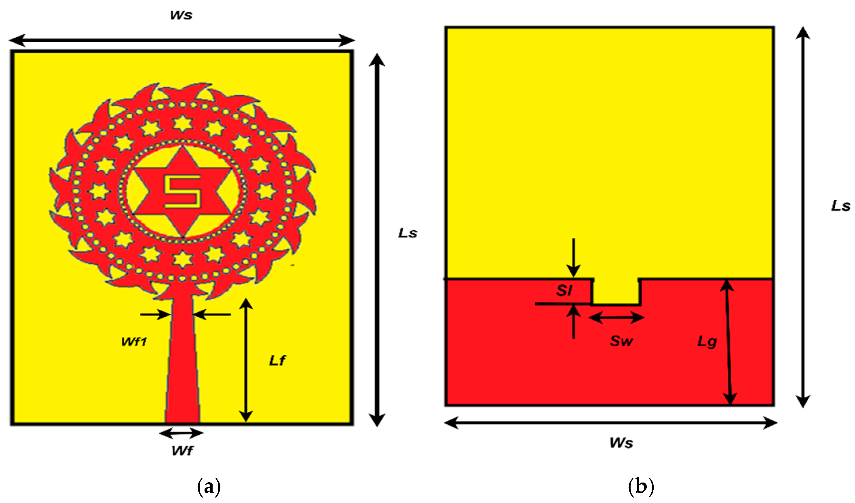
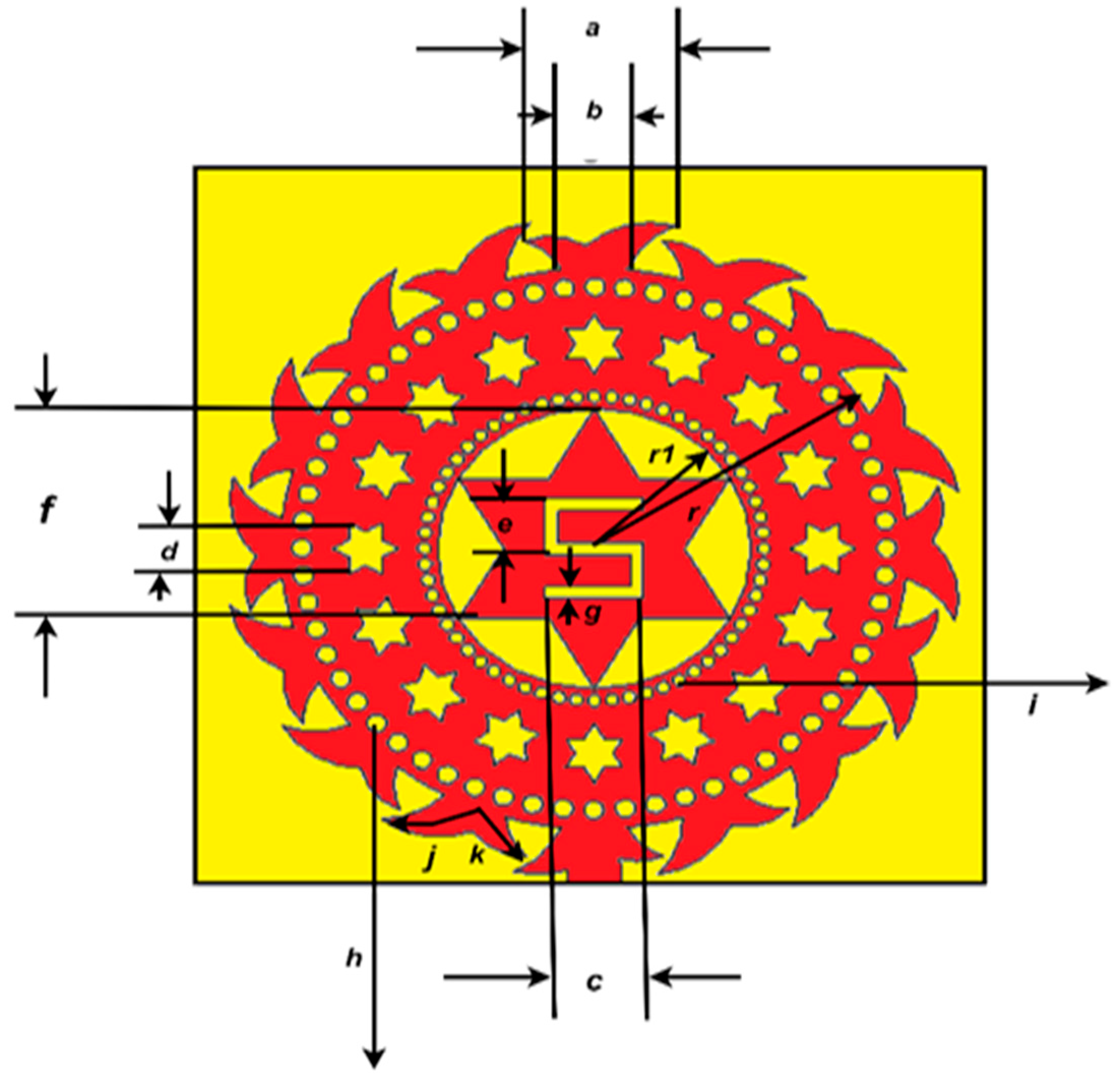
Fractal structures are complex geometrical shapes that exhibit self-similarity across different scales. This property makes fractals look intricate to achieve better performance. The inscribed fractal antenna design contains a circular radiating patch with slits and slots, as portrayed in Figure 2. The outer edge of the antenna resembles the shape of fish tails. The ground plane is partially used with a rectangular notch in the middle of it. The antenna’s front and back views with its dimensions are illustrated in Figure 2a,b, respectively. The projected view of the antenna’s patch with geometrical attributes is displayed in Figure 3. The intended antenna, fabricated with FR-4 substrate measures an overall compact dimension of 24 × 40 × 1.6 mm3. The dimensions of the finalized design attributes are outlined in Table 1.

4. Iteration Procedure for Achieving the Final Design

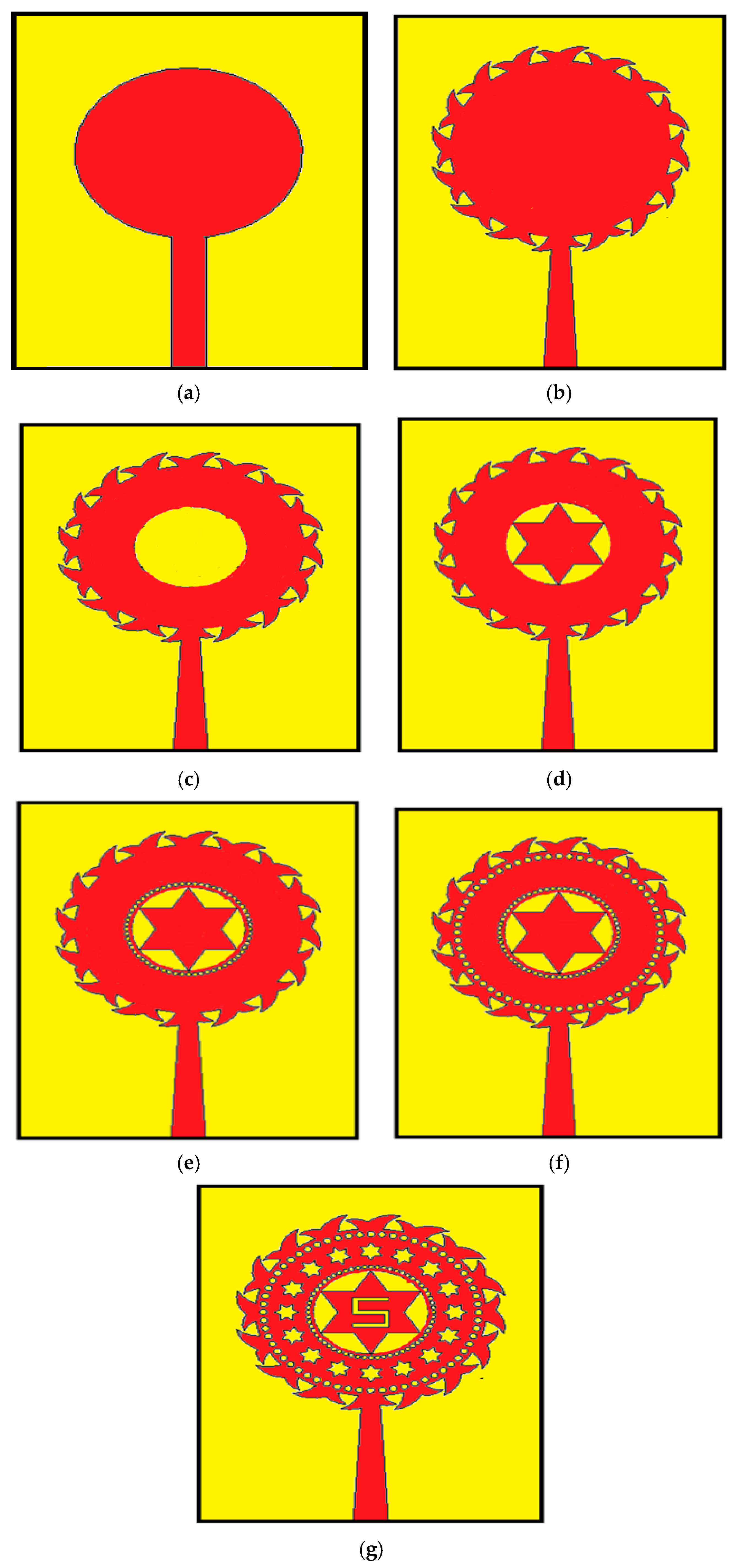
The design process of the suggested radiator starts with designing a basic circular patch (Figure 4a), then fish tail-shaped structures are immediately appended around the circular patch (see Figure 4b). In Figure 4c, a circular slot is etched from the center of the patch to improve EM (Electromagnetic) radiation. A star shape is appended at the middle of the complementary circular-shaped patch, as shown in Figure 4d, and complementary circle-shaped slots with different dimensions are immediately appended around the star-shaped metallic part and the bases of the fish-tail shaped parts, as shown in Figure 4e,f to improve the performance of the proposed antenna. Finally, a complementary S-shape logo slot (Figure 4g) is inserted on the star shape to achieve the final design with better performance characteristics.
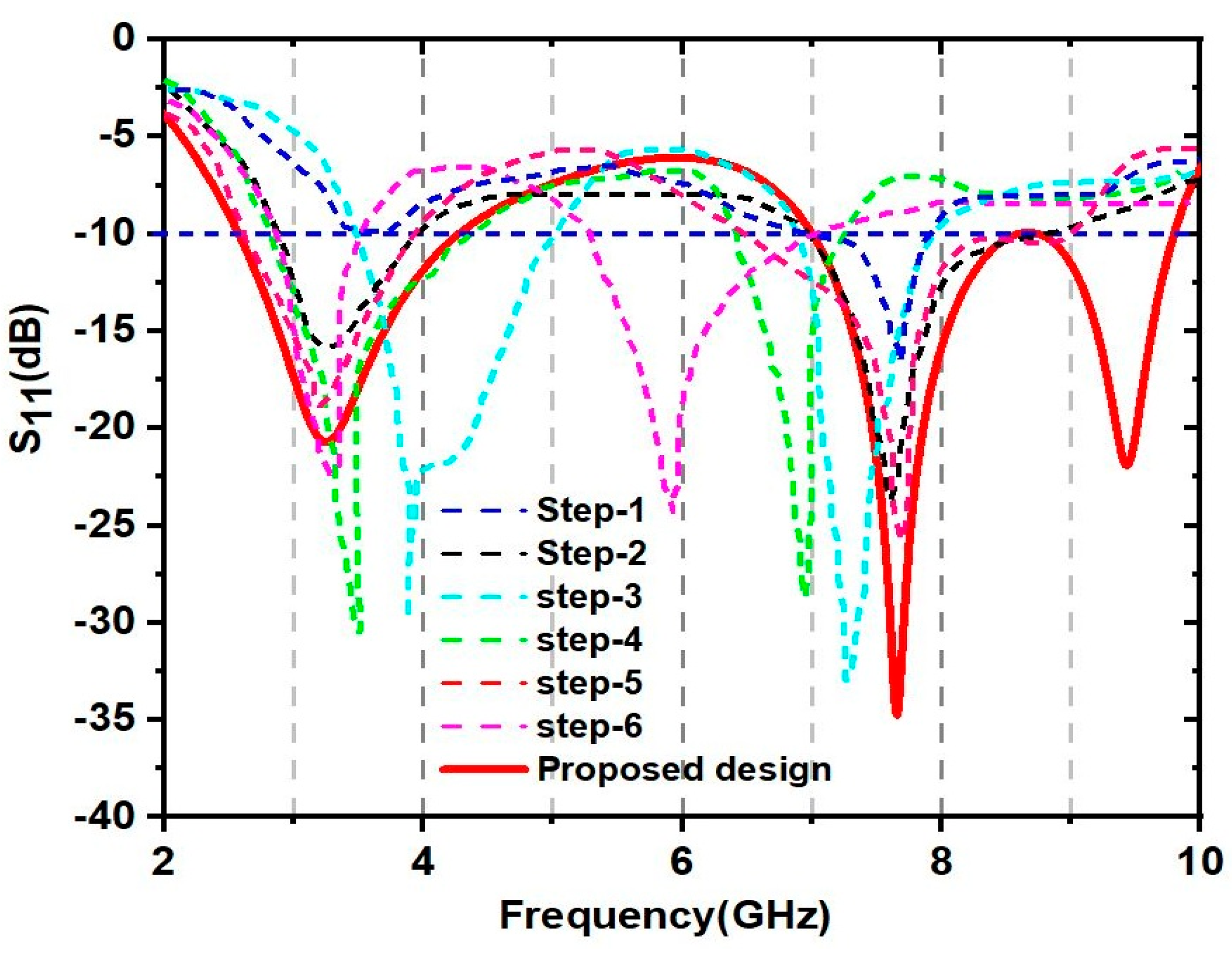
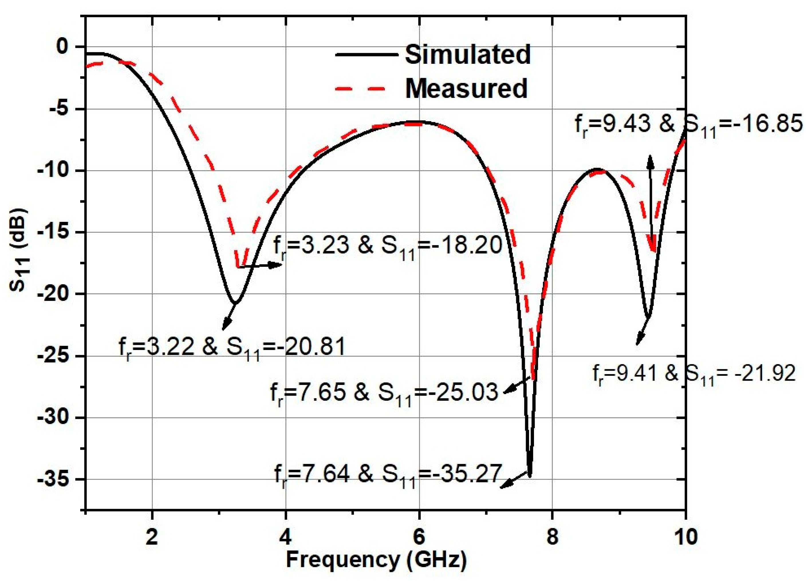
Figure 5 reflects the values of the obtained S11 (dB) for the corresponding iterations. It can be noted that the proposed fractal radiator operates at three distinct resonant frequencies (3.22, 7.64, and 9.41 GHz), covering two independent frequency bands, ranging from 2.5 to 4.2 GHz and 7 to 9.8 GHz. The S11 magnitude at 3.22 GHz is −20.81 dB, 7.64 GHz is −35.27 dB, and 9.41 GHz is −21.92 dB.

5. Parametric Analysis for Achieving the Final Design

In this section, the effects of different ground plane structures, various design parameters, and dielectric materials are investigated to obtain and retain the intended geometry of the fractal antenna with optimal performance.

5.1. Effect of Various Ground Plane Structures on the Performance of the Proposed Antenna

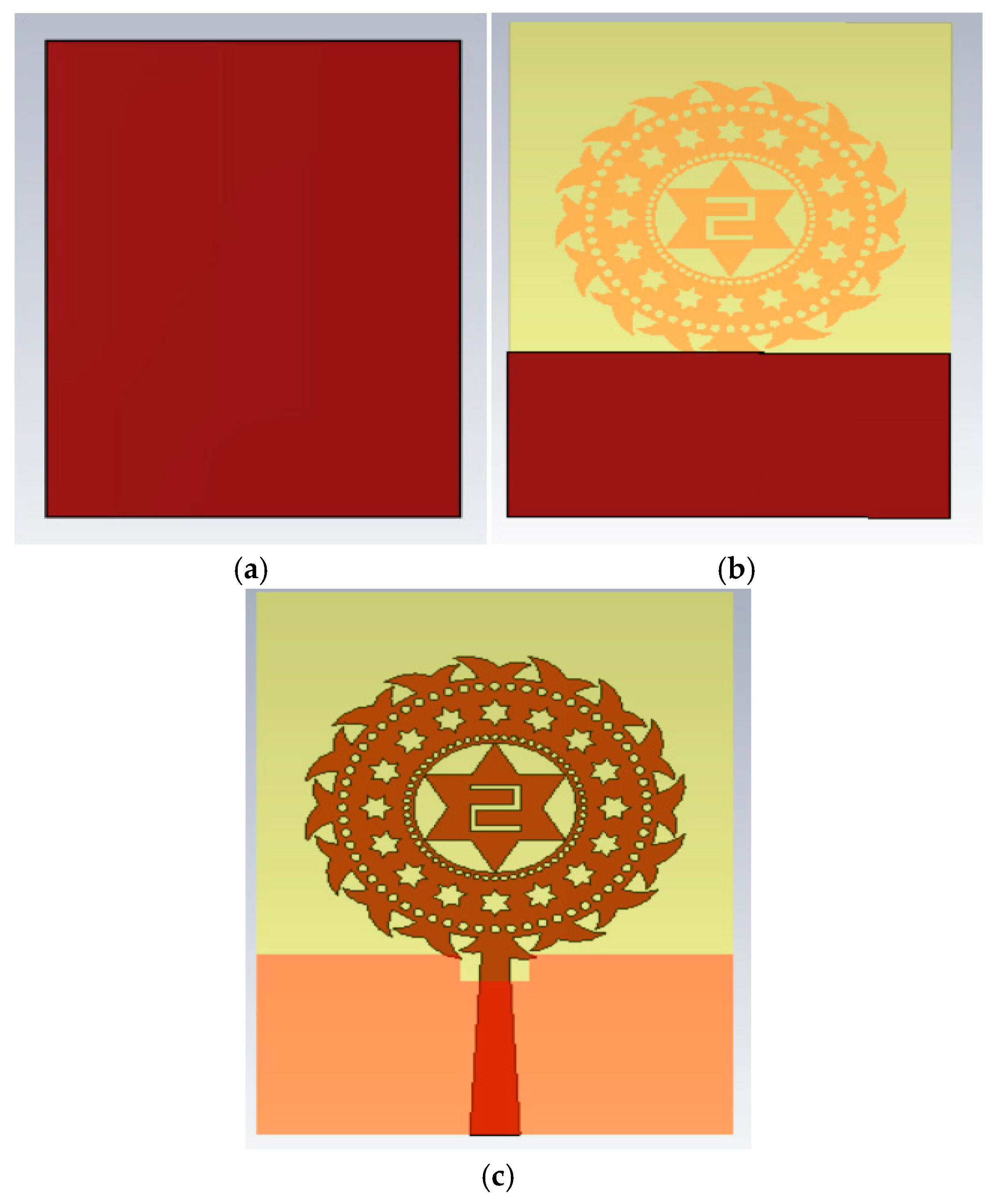
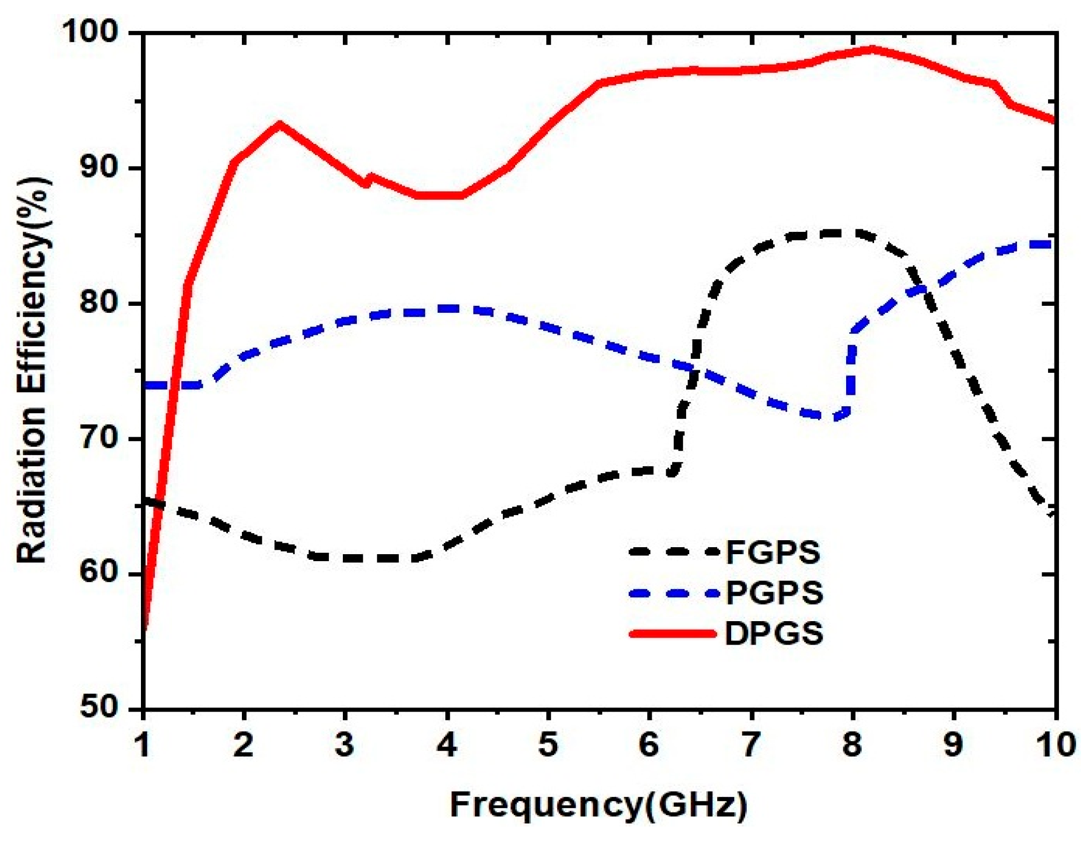
The geometry of the intended fractal patch has been finalized using different iteration steps, as presented in Figure 4a–g. The designed fractal patch has been placed on three different ground plane structures such as FGPS (Full ground plane structure), PGPS (Partial ground plane structure), and DPGS (Defected partial ground structure) to observe their impacts on the performance of the antenna. The various ground plane configurations are demonstrated in Figure 6. The important characteristics parameters, such as reflection coefficient (S11), gain, and radiation efficiency, are analyzed for these three ground plane geometries. The variations in S11 (dB) are represented in Figure 7. It can be noted that dual narrow resonant frequencies can be achieved with a full conductive ground layer. When the ground plane has been changed to a partial configuration, a slight improvement in bandwidth is observed. Finally, due to the addition of a rectangular defect in the partial ground plane (DPGS), better performance in terms of S11 and bandwidth (indicated with red colored spectrum) is achieved, as shown in Figure 7. Similarly, the proposed antenna with DPGS offers much-improved gain and radiation efficiency compared to the antenna structures designed with FGPS and PGPS, as shown in Figure 8 and Figure 9, respectively.

5.2. Effect of Various Parameters of Defected Partial Ground Structure (DPGS)

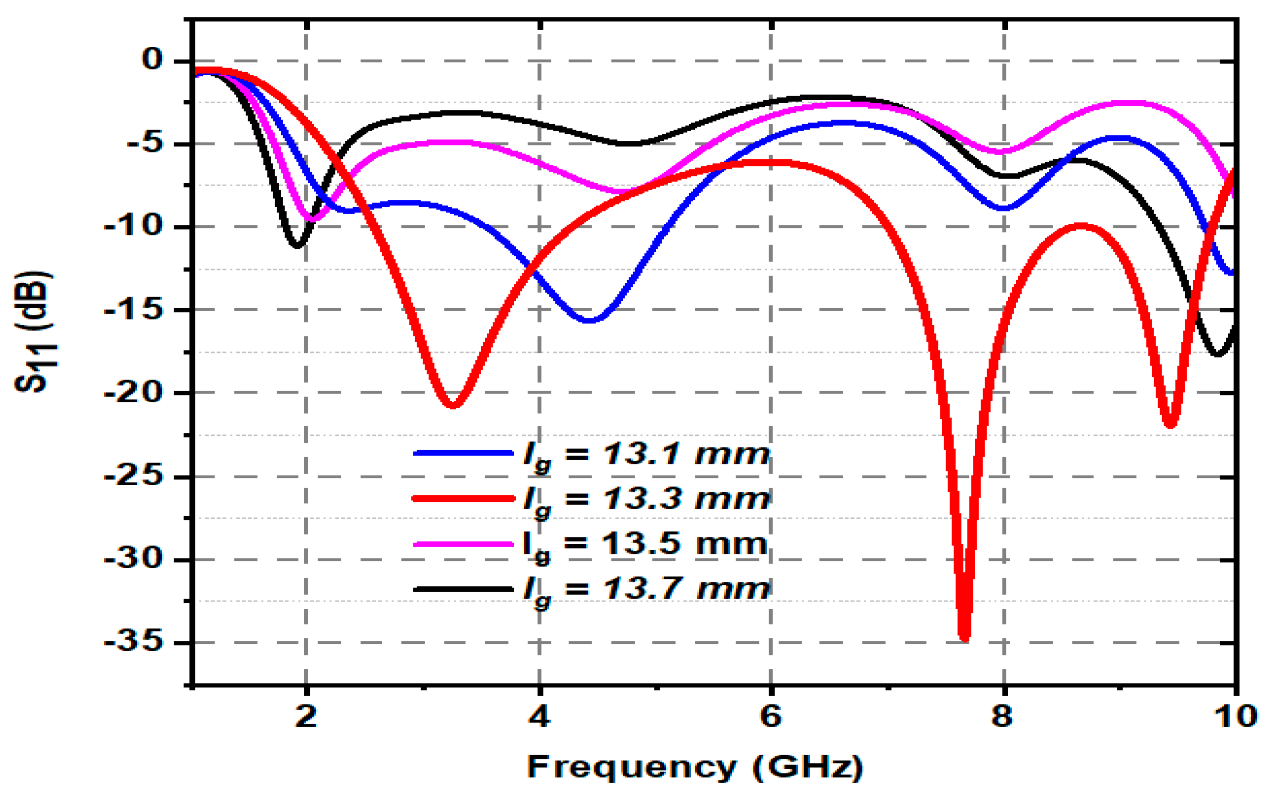
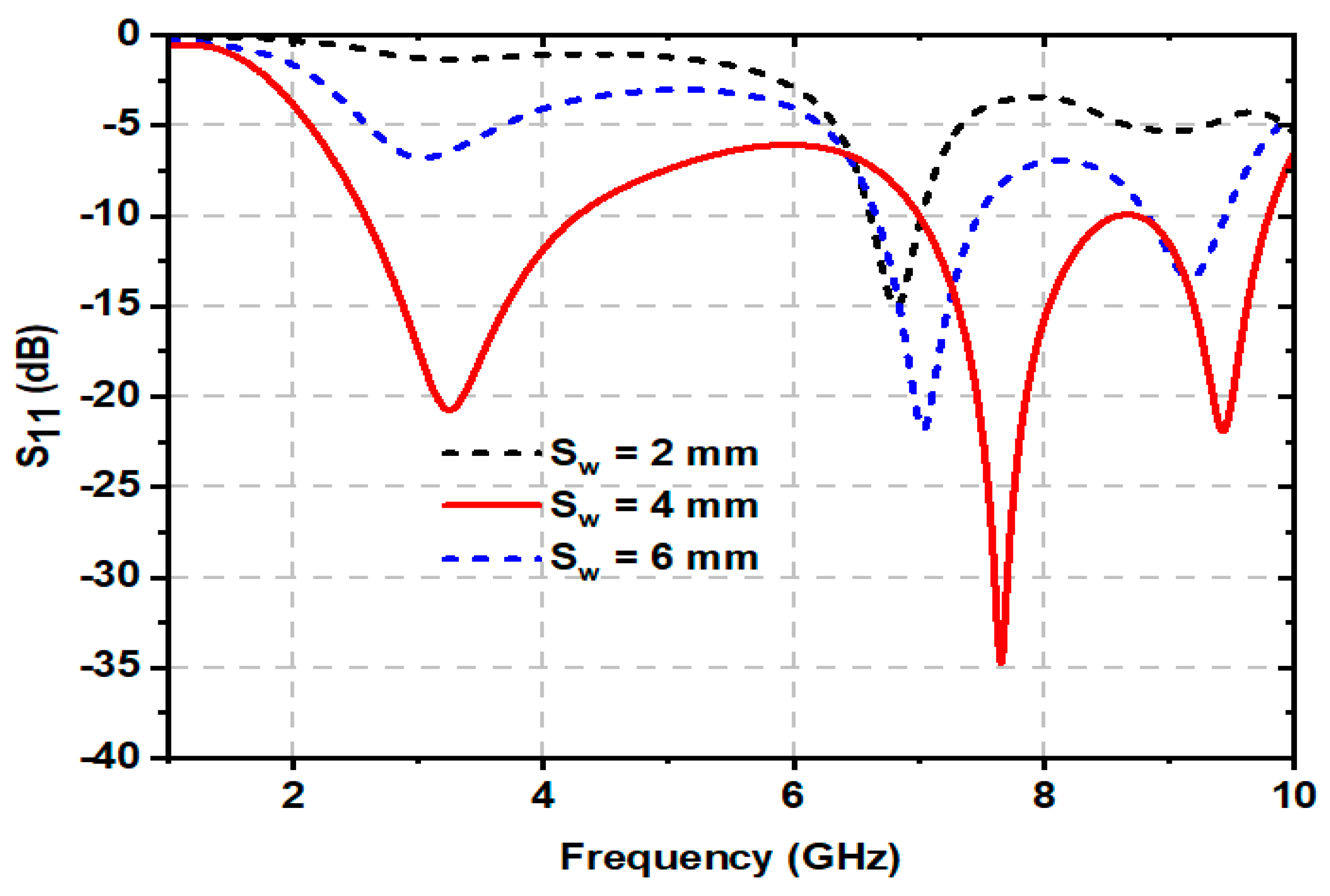
The defected partial ground plane’s structural attributes are also analyzed to extract better characteristic parameters from the antenna. The changes in reflection coefficients (S11 (dB)) due to variance in the length of the ground (lg) parameter are showcased in Figure 10. The parameter lg has been tuned from 13.1 mm to 13.7 mm with a step size of 0.2 mm. It is clearly evident that the best performance is attained at the ground length of 13.3 mm. Similarly, the optimal dimensions of the rectangular ground plane slot are justified through parametric finalization. Sw presents the width of the ground slot, while its length is represented by Sl. The Sw parameter has been varied with a step of 2 mm (2 mm to 6 mm) and Sl is varied from 1 mm to 3 mm with a difference of 1 mm. As a result of these variations, the corresponding S11 (dB) responses are plotted in Figure 11 and Figure 12, respectively. It is worth noting that optimal performance is achieved by keeping a slot of 4 mm width (Sw) and a slot of 2 mm length (Sl) at the ground plane.

5.3. Effect of Various Dielectric Materials

Three different dielectric materials are inspected to test their impact on the antenna’s performance. The investigations have been carried out using the CST studio. The variations in resonance characteristics (reflection coefficients vs frequency) due to the placement of Rogers RT 5880, Polyimide, and FR-4 dielectric materials are highlighted in Figure 13. It is a fact that a better performance in terms of better impedance matching and broader bandwidths at dual operating bands with three separate resonating frequencies is obtained for FR-4 material, which is marked with a red-colored representation in Figure 13.

6. Prototype Fabrication and Validation Through Results Analysis

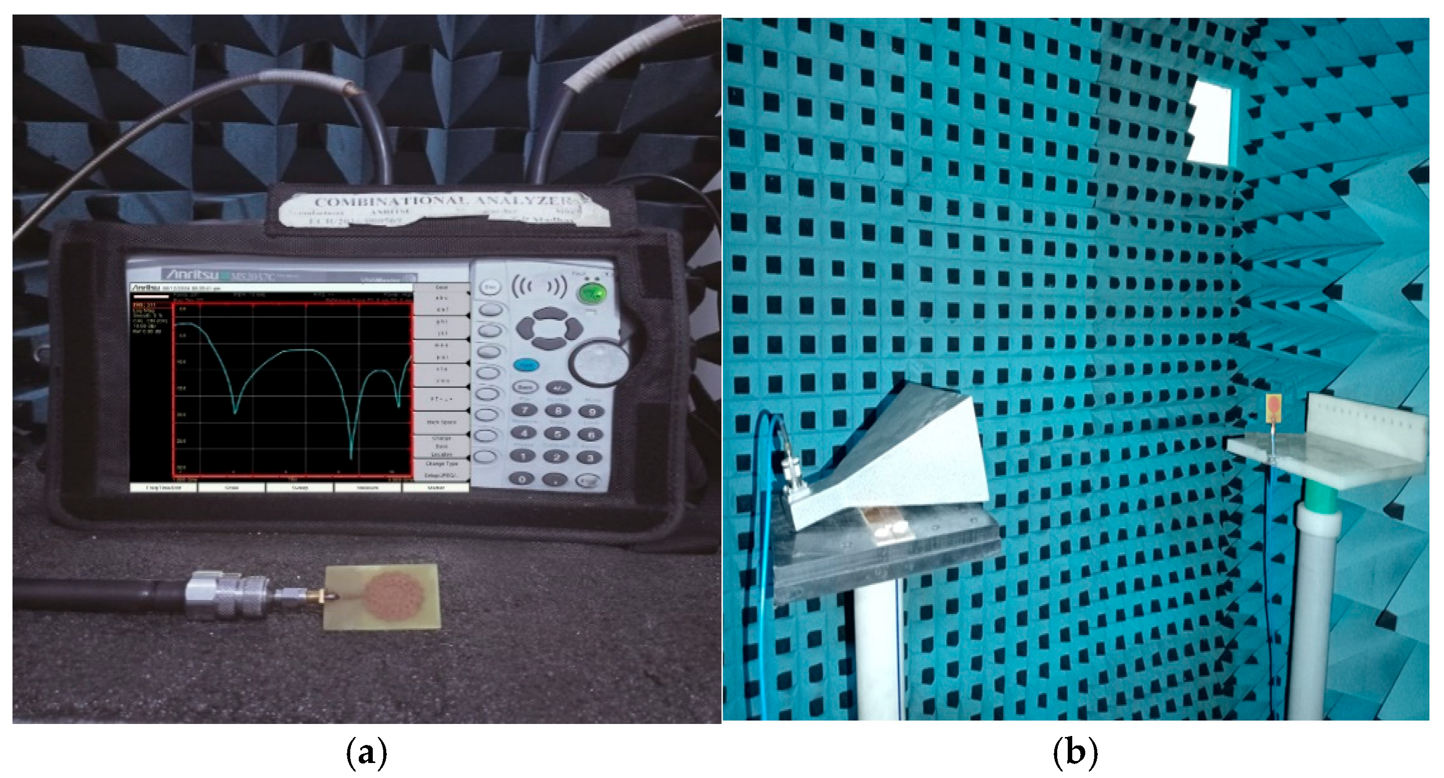
The proposed antenna has been successfully fabricated using photo etching to attain high prototyping accuracy. The fabricated fractal prototype is shown in Figure 14. The prototype’s S-parameter is measured using a calibrated combinational vector network analyzer (Anritsu MSC2037C) as displayed in Figure 15a and radiation characteristics are tested in an anechoic chamber, placing the proposed antenna as antenna under test (AUT) concerning a reference horn antenna, as shown in Figure 15b. The radiation patterns are measured with an automated software-driven rotating table mechanism to record the data at each radiating angle.
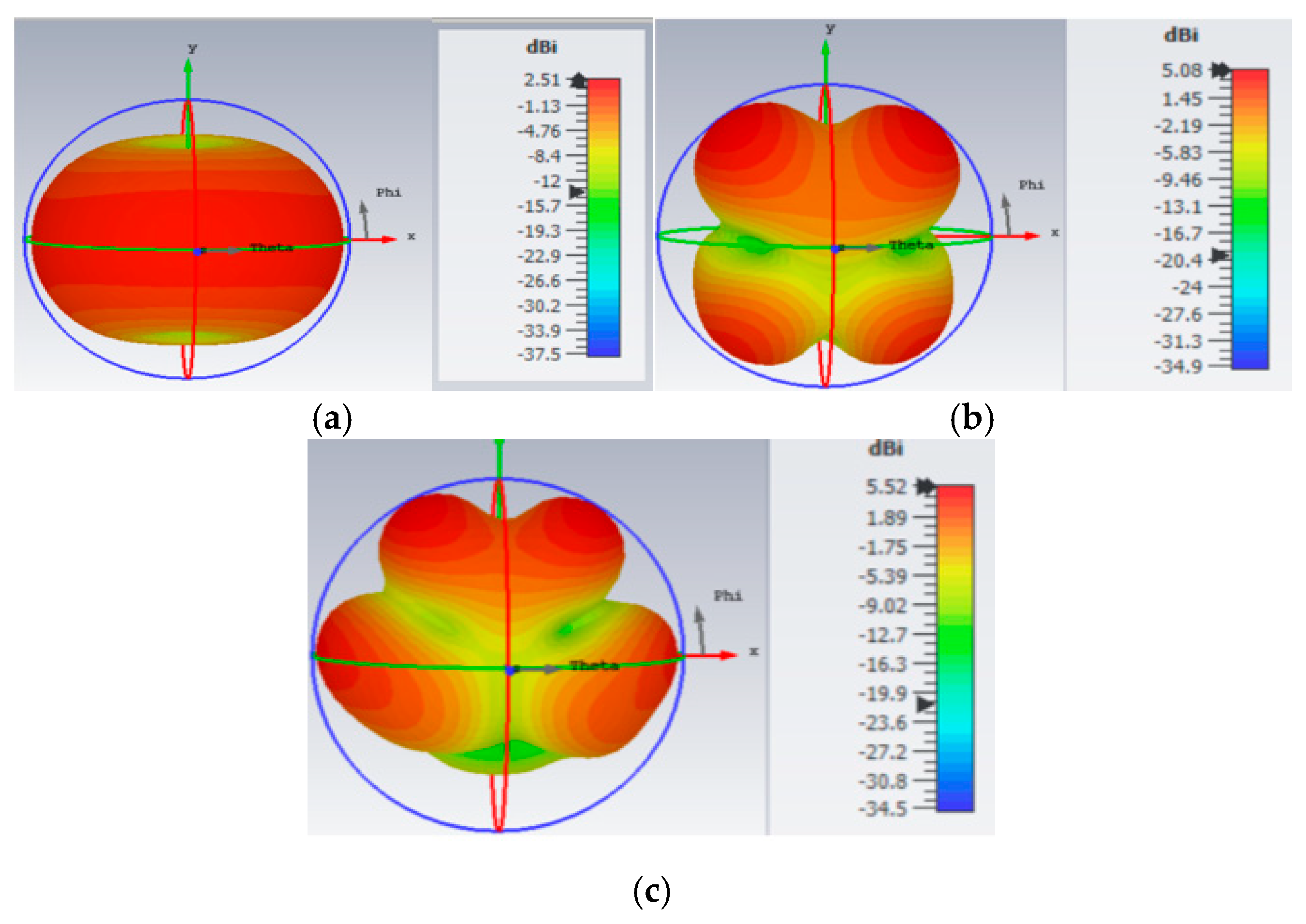
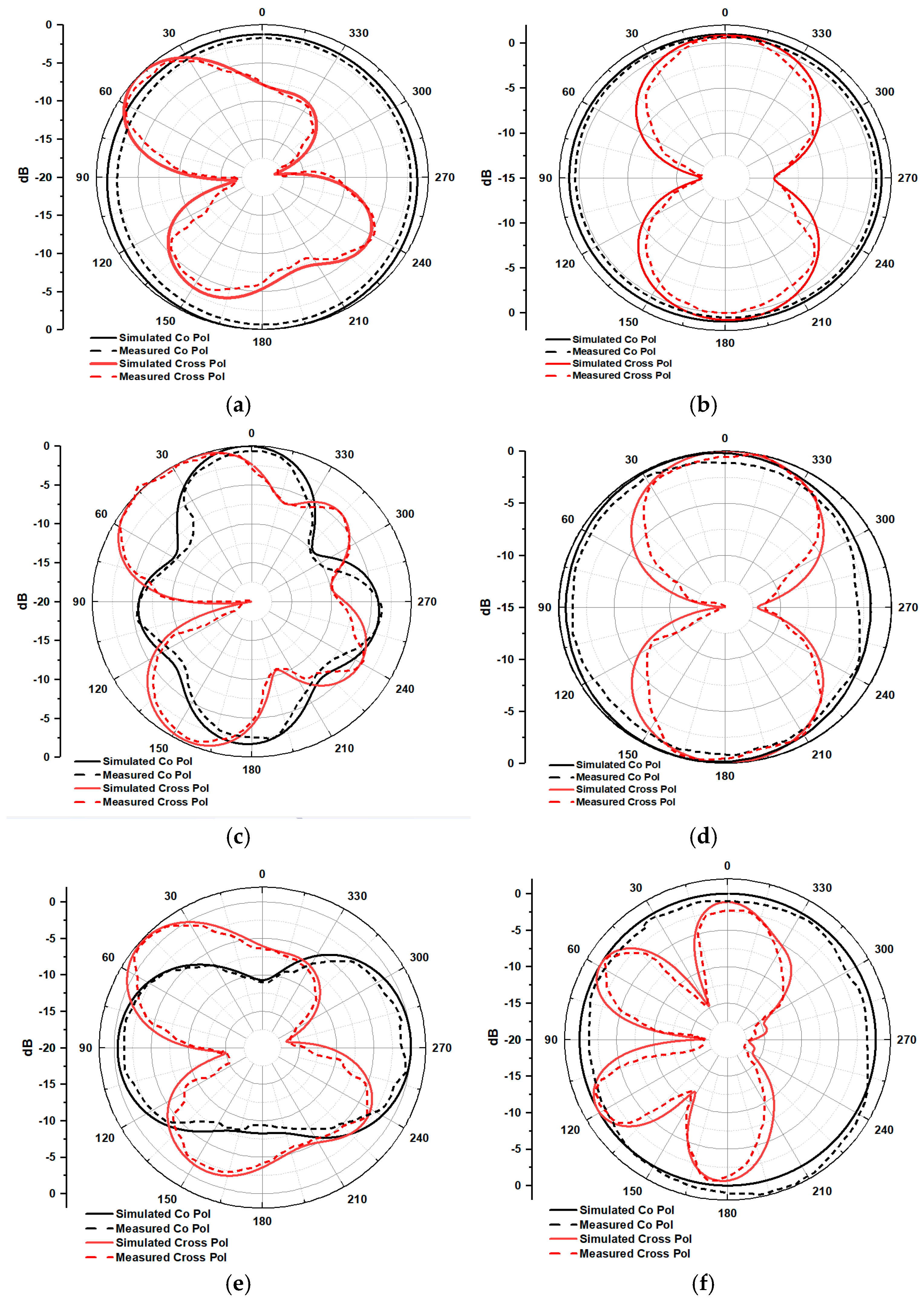
Figure 16 shows the functioning of the propounded antenna at three different resonant frequencies with dual broad operating bandwidths. The testified prototype delivers results in good agreement with the simulation outcomes. As per simulation, the antenna operates across three distinct frequencies, namely 3.22, 7.64, and 9.41 GHz, with S11 magnitudes of −20.81, −35.27, and −21.92 dB, respectively. The measurement results also verify the presence of the same resonant frequencies across the operating bands. As per measurements, the S11 magnitude at 3.23 GHz is −18.20 dB, at 7.65 GHz is −25.03 dB, and finally, at 9.43 GHz, it equals −16.85 dB. The three-dimensional (3D) patterns, generated from the CST tool are shown in Figure 17. Furthermore, the simulated co- and cross-polar views in both E and H planes are verified with experimental results and presented in Figure 18a–f.
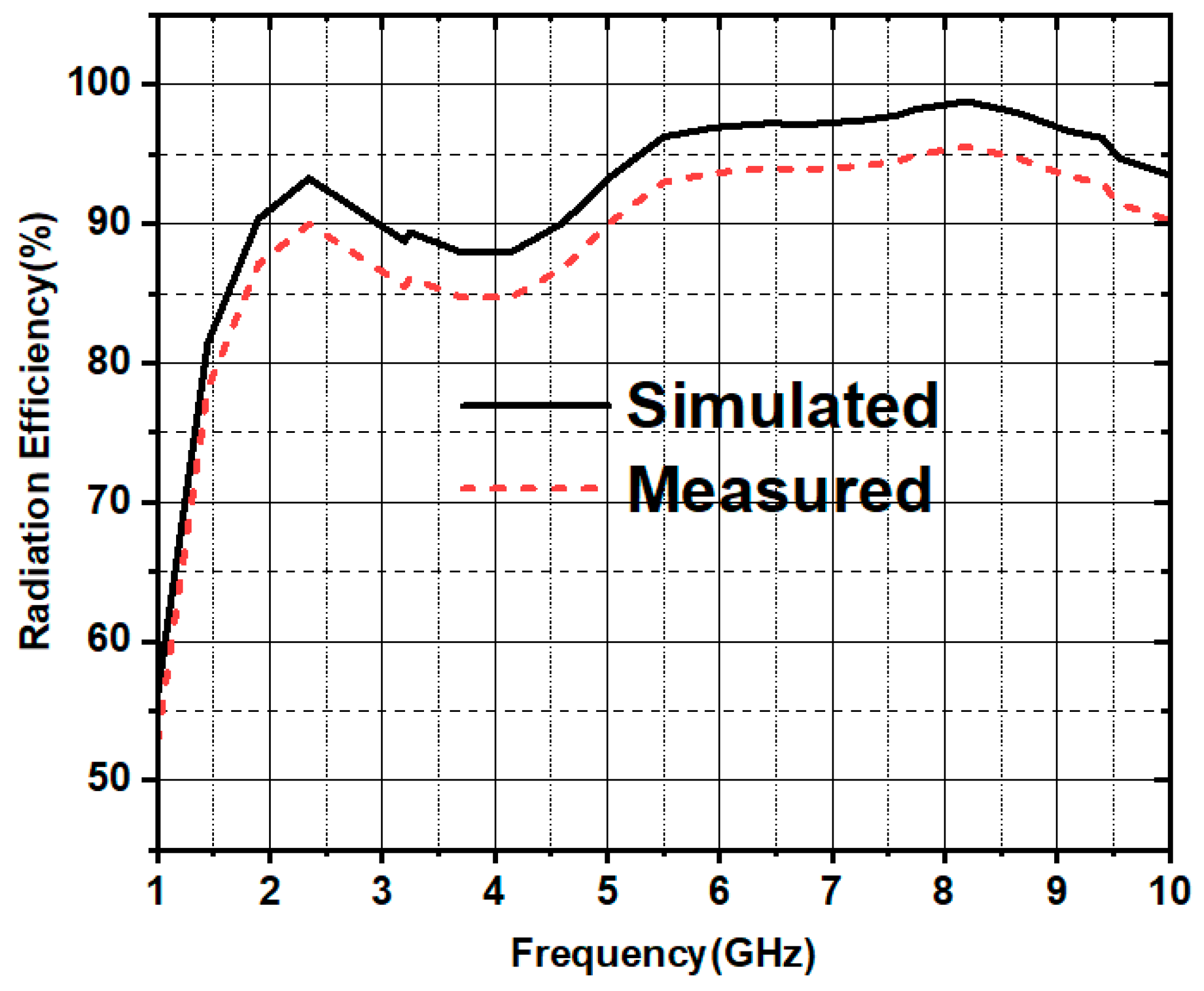
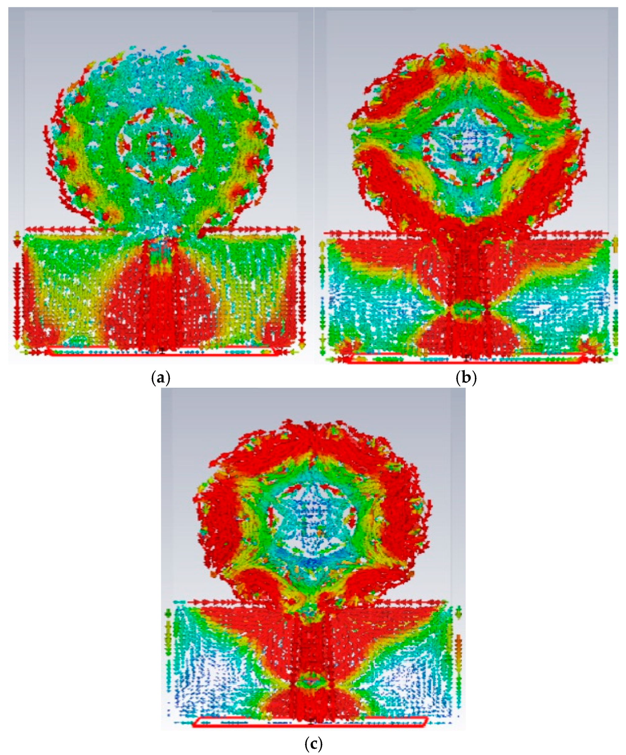
Figure 19 depicts the gain graph, demonstrating its linear increment with the rise in its operating frequencies. It can be noted that at 9.4 GHz frequency (higher operating band), a maximum gain of 5.35 dBi is outlined. Radiation efficiency is also an important metric in determining antenna performance. As observed from Figure 20, the proposed antenna has obtained a peak efficiency of 98% over the operating frequency band and maintains above 85% radiation efficiency over the complete performing band. The current distributions at three resonant frequencies are demonstrated in Figure 21. It clearly shows that at 3.2 GHz frequency, a maximum amount of current can be formed on the feed line, while at 7.6 and 9.4 GHz frequencies, a maximum current is formed at the entire circular typed ring and the feedline.

7. Equivalent Circuit Discussion

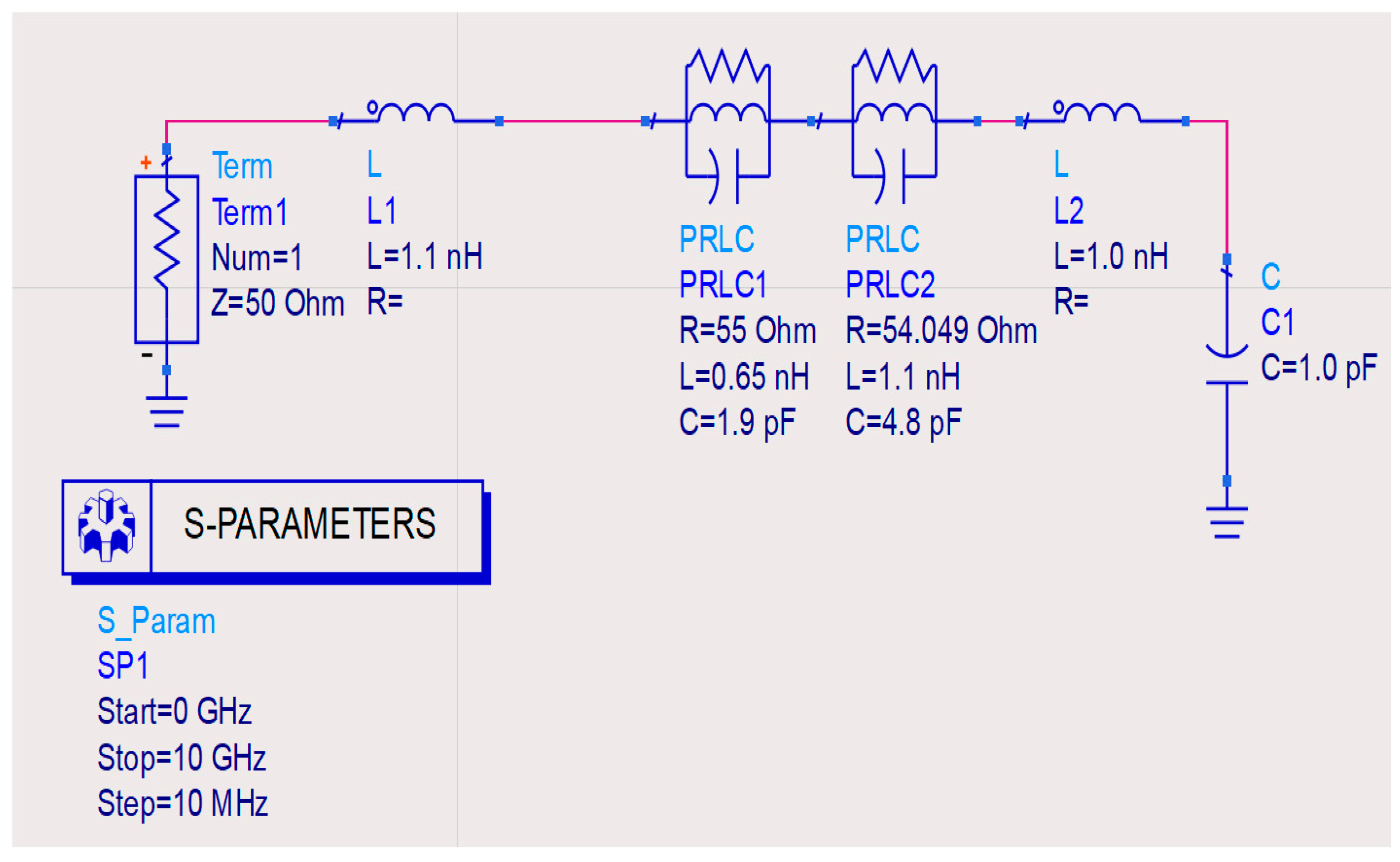
The equivalent circuit modeling (ECM) of an antenna is another method for testing the antenna’s performance. An ideal method for modelling the ECM of any antenna, including dipoles and monopoles, is the Foster canonical form [30,31,32,33]. The Foster canonical form approach uses a parallel R-L-C combination to produce a wide range of resonant frequencies. Figure 22 illustrates the estimation of the proposed antenna using passive elements, followed by the implementation of the complete antenna structure in the ADS tool. A 50-ohm impedance is connected to the RF feed of the antenna to ensure appropriate impedance matching; this is necessary to generate the exact S-parameter response, as shown in Figure 23. We employ two parallel RLC (PRLC) combinations to achieve the desired return loss (S11) response. The (L2-C1) combination represents the ground layer of the proposed antenna, with an inductor (L2) representing the conductive layer and a capacitor (C1) representing the gap in the ground layer. The tuning feature of the ADS tool is used to obtain optimized values for all R, L, and C components shown in Figure 22. We configure the start and end frequencies of the ADS tool simulation to be 0 GHz and 10 GHz, respectively, with a step size of 10 MHz. Figure 23 shows that the X-axis defines the frequency range while the Y-axis selects the S11 (dB). The responses of S11 (dB) obtained from the CST and ADS tools are nearly identical.

8. Comparative Analysis

The prescribed fractal antenna and other mentioned antennas are compared in terms of various characteristics, illustrated in Table 2. The suggested fractal antenna highlights considerable performance parameters concerning gain and operational bandwidth by maintaining compactness, novel design, and low fabrication cost.

9. Conclusions

A novel triple-band fractal monopole antenna with a modified partial ground structure (PGS) is designed, analyzed, and experimentally tested. It exhibits exceptional performance in the S, C, and X bands. The designed fractal radiator can operate at three distinct resonant frequencies (3.22, 7.64, and 9.41 GHz), covering two unique frequency bands, extending from 2.5 to 4.2 GHz and 7 to 9.8 GHz. The overall performance of the antenna is analyzed, which shows that it is more effective and reliable because of its radiation efficiency of 98% along with a peak gain of 5.35 dBi. The proposed compact radiator possesses reasonable gain and dual broad operational bandwidth. The suggested fractal radiator is a fruitful choice for sub-6GHz 5G and X-band radar applications.

Author Contributions

Conceptualization, G.Y., P.P., N.P., S.D., A.D.A.; methodology, G.Y., S.D., B.T.P.M., M.E.G.; software, G.Y, N.P.; validation, P.P., B.T.P.M., S.D.; formal analysis, G.Y., N.P., A.D.A., M.E.G.; investigation, S.D., B.T.P.M., P.P.; data curation, G.Y., N.P., M.E.G.; writing—original draft preparation, G.Y., N.P., S.D., A.D.A.; writing—review and editing, P.P., B.T.P.M., M.E.G.; visualization, M.E.G., N.P.; Resources, B.T.P.M., A.D.A.; supervision, P.P.; project administration, A.D.A. All authors have read and agreed to the published version of the manuscript.

Funding

This research was funded by Princess Nourah bint Abdulrahman University Researchers Supporting Project number (PNURSP2025R51), Princess Nourah bint Abdulrahman University, Riyadh, Saudi Arabia.

Data Availability Statement

Data are contained within the article.

Acknowledgments

The authors extend their appreciation to Princess Nourah bint Abdulrahman University Researchers Supporting Project number (PNURSP2025R51), Princess Nourah bint Abdulrahman University, Riyadh, Saudi Arabia.

Conflicts of Interest

The authors declare no conflicts of interest.

References

  1. Werner, D.H.; Ganguly, S. An overview of fractal antenna engineering research. IEEE Antennas Propag. Mag. 2003, 45, 38–57. [Google Scholar] [CrossRef]
  2. Bisht, N.; Malik, P.K.; Das, S.; Islam, T.; Asha, S.; Alathbah, M. Design of a Modified MIMO Antenna Based on Tweaked Spherical Fractal Geometry for 5G New Radio (NR) Band N258 (24.25–27.25 GHz) Applications. Fractal Fract. 2023, 7, 718. [Google Scholar] [CrossRef]
  3. Kundu, S.; Jana, S.K. Leaf shaped CPW fed UWB antenna with triple notch bands for ground penetrating radar applications. Microw. Opt. Technol. Lett. 2018, 60, 930–936. [Google Scholar] [CrossRef]
  4. Li, L.; Zhang, X.; Yin, X.; Zhou, L. A Compact Triple-Band Printed Monopole Antenna for WLAN/WiMAX Applications. IEEE Antennas Wirel. Propag. Lett. 2016, 15, 1853–1855. [Google Scholar] [CrossRef]
  5. Guenad, B.; Chaabane, A.; Aissaoui, D.; Bouacha, A.; Denidni, T.A. Compact Cauliflower-Shaped Antenna for Ultra-Wideband Applications. ACES J. 2023, 37, 68–77. [Google Scholar] [CrossRef]
  6. Varun Yadav, M.; Yadav, S.V.; Ali, T.; Dash, S.K.K.; Hegde, N.T.; Nair, V.G. A cutting-edge S/C/X band antenna for 5G and beyond application. AIP Adv. 2023, 13, 105123. [Google Scholar] [CrossRef]
  7. Varun Yadav, M.; Baudha, S.; Sanghi, V. A 5G rotated frame radiator for ultra-wideband microwave communication. Int. J. Microw. Wirel. Technol. 2023, 15, 1262–1270. [Google Scholar] [CrossRef]
  8. Benkhadda, O.; Ahmad, S.; Saih, M.; Chaji, K.; Reha, A.; Ghaffar, A.; Khan, S.; Alibakhshikenari, M.; Limiti, E. Compact Broadband Antenna with Vicsek Fractal Slots for WLAN and WiMAX Applications. Appl. Sci. 2022, 12, 1142. [Google Scholar] [CrossRef]
  9. Benkhadda, O.; Saih, M.; Ahmad, S.; Al-Gburi, A.J.A.; Zakaria, Z.; Chaji, K.; Reha, A. A Miniaturized Tri-Wideband Sierpinski Hexagonal-Shaped Fractal Antenna for Wireless Communication Applications. Fractal Fract. 2023, 7, 115. [Google Scholar] [CrossRef]
  10. Gupta, M.; Mathur, V. Hexagonal Fractal Antenna using Koch for Wireless Applications. Frequenz 2018, 72, 9–10. [Google Scholar] [CrossRef]
  11. Khan, M.A.; Rafique, U.; Savci, H.Ş.; Nordin, A.N.; Kiani, S.H.; Abbas, S.M. Ultra-Wideband Pentagonal Fractal Antenna with Stable Radiation Characteristics for Microwave Imaging Applications. Electronics 2022, 11, 2061. [Google Scholar] [CrossRef]
  12. Sun, L.; He, M.; Hu, J.; Zhu, Y.; Chen, H. A butterfly-shaped wideband microstrip patch antenna for wireless communication. Int. J. Antennas Propag. 2015, 2015, 328208. [Google Scholar] [CrossRef]
  13. Puri, S.C.; Das, S.; Tiary, M.G. A multi-band antenna using plus-shaped fractal-like elements and stepped ground plane. Int. J. RF Microw. Comput. Aided Eng. 2020, 30, e22169. [Google Scholar] [CrossRef]
  14. Samson Daniel, R. Asymmetric coplanar strip-fed with Hilbert curve fractal antenna for multiband operations. Wirel. Pers. Commun. 2020, 116, 791–803. [Google Scholar] [CrossRef]
  15. Kalkhambkar, G.B.; Khanai, R.; Chindhi, P. Design and Characteristics Mode Analysis of a Cantor Set Fractal Monopole Antenna for IoT Applications. Prog. Electromagn. Res. C 2022, 119, 161–175. [Google Scholar] [CrossRef]
  16. Ez-Zaki, F.; Belahrach, H.; Ghammaz, A. Broadband microstrip antennas with Cantor set fractal slots for vehicular communications. Int. J. Microw. Wirel. Technol. 2021, 13, 295–308. [Google Scholar] [CrossRef]
  17. Nejdi, I.H.; Bri, S.; Marzouk, M.; Ahmad, S.; Rhazi, Y.; Ait Lafkih, M.; Sheikh, Y.A.; Ghaffar, A.; Hussein, M. UWB Circular Fractal Antenna with High Gain for Telecommunication Applications. Sensors 2023, 23, 4172. [Google Scholar] [CrossRef]
  18. Marzouk, M.; Rhazi, Y.; Nejdi, I.H.; Zerrad, F.-E.; Saih, M.; Ahmad, S.; Ghaffar, A.; Hussein, M. Ultra-Wideband Compact Fractal Antenna for WiMAX, WLAN, C and X Band Applications. Sensors 2023, 23, 4254. [Google Scholar] [CrossRef]
  19. Li, Y.; Yang, X.-D.; Liu, C.-Y.; Jiang, T. Analysis and Investigation of a Cantor Set Fractal UWB Antenna with a Notch-Band Characteristic. Prog. Electromagn. Res. B 2021, 33, 99–114. [Google Scholar] [CrossRef]
  20. Cao, Y.F.; Cheung, S.W.; Yuk, T.I. A Multiband Slot Antenna for GPS/WiMAX/WLAN Systems. IEEE Trans. Antennas Propag. 2015, 63, 952–958. [Google Scholar] [CrossRef]
  21. Shankar, S.; Upadhyay, D.K. A Fractal Monopole Antenna With Dual Polarization Reconfigurable Characteristics for X-Band Applications. IEEE Access 2023, 11, 95667–95680. [Google Scholar] [CrossRef]
  22. Amirinalloo, S.; Atlasbaf, Z. A CPW-fed fractal monopole antenna with a reduced ground plane in frequency range of 500 MHz-5.5 GHz. IET Microw. Antennas Propag. 2023, 17, 1006–1014. [Google Scholar] [CrossRef]
  23. Yassen, M.T.; Salim, A.J.; Hussan, M.R.; Ali, J.K. A Compact Dual-Band Dual-Polarized Antenna Based on Modified Minkowski Fractal. Prog. Electromagn. Res. C 2024, 140, 11–19. [Google Scholar] [CrossRef]
  24. Singh, S.; Varshney, A.; Sharma, V.; Elfergani, I.T.; Zebiri, C.; Rodriguez, J. A Compact off -Set Edge Fed Odd-Symmetric Hybrid Fractal Slotted Antenna for UWB and Space Applications. Prog. Electromagn. Res. B 2023, 102, 37–60. [Google Scholar] [CrossRef]
  25. Patel, U.; Upadhyaya, T.; Sorathiya, V.; Pandya, K.; Alwabli, A.; Dave, K.; Soliman, N.F.; El-Shafai, W. Split ring resonator geometry inspired crossed flower shaped fractal antenna for satellite and 5G communication applications. Results Eng. 2024, 22, 102110. [Google Scholar] [CrossRef]
  26. Palanisamy, S.; Vaddinuri, A.R.; Khan, A.A.; Faheem, M. Modeling of Inscribed Dual Band Circular Fractal Antenna for Wi-Fi Application Using Descartes Circle Theorem. Eng. Rep. 2024, e13019. [Google Scholar] [CrossRef]
  27. Rabie, M.M.; El-Gendy, M.S.; Eldamak, A.R.; Ibrahim, F.; El-Henawy, H. A compact wideband circularly polarized fractal slot antenna with rectangular island for X-band satellite applications. Cogent Eng. 2024, 11, 2322813. [Google Scholar] [CrossRef]
  28. Varshney, A.; Gençoğlan, D.N. High-Gain Multi-Band Koch Fractal FSS Antenna for Sub-6 GHz Applications. Appl. Sci. 2024, 14, 9022. [Google Scholar] [CrossRef]
  29. Ojaroudi Parchin, N.; Basherlou, H.J.; Abd-Alhameed, R.A.; Noras, J.M. Dual-band monopole antenna for RFID applications. Future Internet 2019, 11, 31. [Google Scholar] [CrossRef]
  30. Ez-Zaki, F.; Belaid, K.A.; Ahmad, S.; Belahrach, H.; Ghammaz, A.; Al-Gburi, A.J.A.; Parchin, N.O. Circuit modelling of broadband antenna using vector fitting and foster form approaches for IoT applications. Electronics 2022, 11, 3724. [Google Scholar] [CrossRef]
  31. Sayidmarie, K.H.; Yahya, L.S. Modeling of dual-band crescent-shape monopole antenna for WLAN applications. Int. J. Electromagn. Appl. 2014, 4, 31–39. [Google Scholar]
  32. Meher, P.R.; Mishra, S.K. Design and Development of Mathematical Equivalent Circuit Model of Broadband Circularly Polarized Semi-Annular Ring-Shaped Monopole Antenna. Prog. Electromagn. Res. C 2023, 129, 73–87. [Google Scholar] [CrossRef]
  33. Srividhya, K.; Jothilakshmi, P. Compact coradiator dual polarized MIMO antenna for future 5G, emerging 6G and IoT applications. Eng. Sci. Technol. Int. J. 2024, 51, 101609. [Google Scholar] [CrossRef]
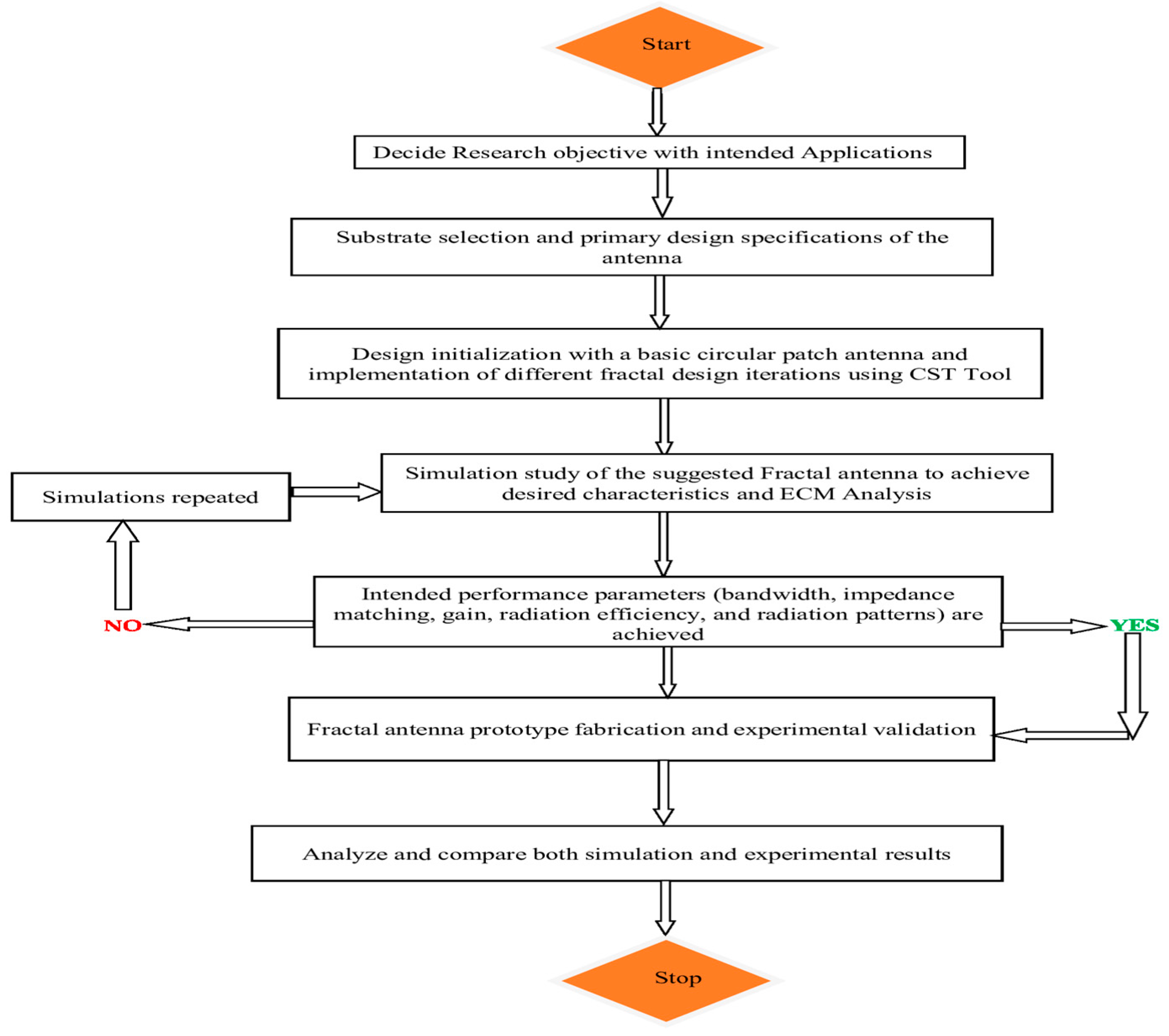
Figure 1. Design framework flowchart of the fractal antenna.
Fractalfract 09 00029 g001
Figure 2. Proposed antenna: (a) front and (b) back views.
Fractalfract 09 00029 g002
Figure 3. Projected view of the radiating patch symbolizing design parameters.
Fractalfract 09 00029 g003
Figure 4. (ag) Different iteration steps for designing the intended antenna.
Fractalfract 09 00029 g004
Figure 5. S11 (dB) values for each iteration step.
Fractalfract 09 00029 g005
Figure 6. Various ground plane configurations: (a) FGPS (Full ground plane structure), (b) PGPS (Partial ground plane structure), (c) DPGS (Defected partial ground structure).
Fractalfract 09 00029 g006
Figure 7. Variations in S11 parameters for various ground plane structures.
Fractalfract 09 00029 g007
Figure 8. Variations in gain for various ground plane structures.
Fractalfract 09 00029 g008
Figure 9. Variations in radiation efficiency for various ground plane structures.
Fractalfract 09 00029 g009
Figure 10. Simulated analysis of S11 (dB) response as a function of lg.
Fractalfract 09 00029 g010
Figure 11. Simulated analysis of S11 (dB) response as a function of Sw.
Fractalfract 09 00029 g011
Figure 12. Simulated analysis of S11 (dB) response as a function of Sl.
Fractalfract 09 00029 g012
Figure 13. S11 (dB) response of the proposed antenna for different dielectric materials.
Fractalfract 09 00029 g013
Figure 14. Fabricated Prototype: (a) Front view, (b) Back view.
Fractalfract 09 00029 g014
Figure 15. Images of the measuring setup of the proposed antenna: (a) VNA snapshot, (b) anechoic chamber with AUT.
Fractalfract 09 00029 g015
Figure 16. Simulated and measured results obtained for S11.
Fractalfract 09 00029 g016
Figure 17. Gains at the corresponding resonating frequencies of (a) 3.22 GHz, (b) 7.64 GHz, and (c) 9.41 GHz.
Fractalfract 09 00029 g017
Figure 18. Co-pol and cross-pol radiation patterns: (a) 3.22 GHz E-Plane, (b) 3.22 GHz H-plane, (c) 7.64 GHz E-Plane, (d) 7.64 GHz H-Plane, (e) 9.41 GHz E-Plane, and (f) 9.41 GHz H-Plane.
Fractalfract 09 00029 g018
Figure 19. Representation of Gain vs Frequency plot using both measurement and simulation results.
Fractalfract 09 00029 g019
Figure 20. Radiation efficiency plot obtained using both measurement and simulation.
Fractalfract 09 00029 g020
Figure 21. Plots of distributed Surface currents at resonating frequencies (a) 3.2 GHz (b) 7.6 GHz (c) 9.4 GHz.
Fractalfract 09 00029 g021
Figure 22. Equivalent circuit of the proposed antenna.
Fractalfract 09 00029 g022
Figure 23. Comparison of the Reflection coefficient in CST and ADS.
Fractalfract 09 00029 g023
Table 1. Dimensions of the proposed antenna.
ParameterDimension (mm)ParameterDimension (mm)
Ws28a2.5
Ls40b4.6
Wf2.95c3
Wf114d1.6
Lf14.6e2
Lg13.3f4.8
Sw2g0.5
Sl4h0.6
r9.6i0.3
r14.8j1.6
k1.0
Table 2. Comparative analysis with the existing literature survey.
Ref. NoAntenna
Overall Size
(mm3)
Type of Substrate
Material
Operating Band
(GHz)
Resonating Frequencies (GHz)Gain
(dBi)
[3]38.31 × 34.52 × 0.8FR-42.68–11.28NM2–5
[5]36.23 × 41 × 1.524RO-4350B3.05–10.96NM1.39–5.68
[8]50 × 50 × 1.6FR-42.48–6.73.6
5.3
2.78
5.32
[13]27 × 50 × 1.6FR-41.63–1.88
4.5–8.5
1.7
4.9
5.7
7.4
8.1
1.79
3.07
2.25
5.05
3.2
[17]40 × 24.5 × 1.6FR-42.70–11.03.17
5.82
7.86
9.16
1.7–6.25
[18]40 × 34 × 1.6FR-42.26–4.10
6.0–9.82
2.8
3.51
6.53
9.37
2.1–9.37
[19]31 × 28 × 1.6FR-43.22–6.53.71
5.9
3.2
4.15
[20]56 × 44 × 0.8NMNM1.57
2.45
3.5
5.2
1.355
3.93
3.502
4.486
[21]42 × 32 × 1.57RT Duriod 58807.95–12.64NM5.71
[22]143.5 × 227.5 × 1.6FR-40.5–5.5NM1.1–2.6
[23]50 × 50 × 1.6FR-41.595–1.958
3.164–3.55
1.8,
3.5
1.25
2.09
[29]38 × 45 × 1.6FR-42.2–2.6
5.3–6.8
2.4
5.8
2
4
Proposed
work
28 × 40 × 1.6FR-42.5–4.2
7–9.8
3.22
7.64
9.41
2.45
5.04
5.35
NM = Not Mentioned.
Disclaimer/Publisher’s Note: The statements, opinions and data contained in all publications are solely those of the individual author(s) and contributor(s) and not of MDPI and/or the editor(s). MDPI and/or the editor(s) disclaim responsibility for any injury to people or property resulting from any ideas, methods, instructions or products referred to in the content.