Article

Mechanism Modeling and Analysis of Fractional-Order Synchronous Generator

College of Electrical Engineering, Guangxi University, Nanning 530004, China
*
Authors to whom correspondence should be addressed.
Fractal Fract. 2025, 9(4), 244; https://doi.org/10.3390/fractalfract9040244
Submission received: 4 March 2025 / Revised: 2 April 2025 / Accepted: 10 April 2025 / Published: 12 April 2025

Abstract

:
This paper investigates the fractional-order characteristics of the stator and rotor windings of a synchronous generator. Utilizing mechanism-based modeling methodology, it pioneers the derivation of the fractional-order voltage equations for a synchronous generator across both the three-phase stationary coordinate system (A, B, C) and the synchronous rotating coordinate system (d, q, 0). Through simplifying assumptions and rigorous derivations, a 2 + α (α ∈ (0, 2)) order synchronous generator model is formulated. This paper develops a digital simulation model of a fractional-order single-machine infinite bus system and analyzes the impact of the order α on the synchronous generator system’s dynamic performance through disturbance simulation experiments. Experimental results demonstrate that under conventional disturbances, increasing α from 0.8 to 1.2 reduces the system oscillation period and frequency while enhancing mechanical oscillation suppression, whereas decreasing α to 0.8 accelerates the generator terminal voltage response, lowers electromagnetic power overshoot, and improves excitation control effectiveness.

1. Introduction

The concept of fractional calculus has a history spanning over 300 years since its inception [1]. For a substantial duration, both the mathematical theories associated with fractional calculus and its practical engineering applications experienced stagnation. It was not until the mid-20th century, with the advent of the transistor and its integration into circuits, that innovations such as computers elevated the research and application of fractional calculus to unprecedented levels [2,3]. In contemporary research, fractional calculus has emerged as a distinct and pivotal discipline within the international scientific community [4,5].
Unlike traditional integer-order calculus, fractional calculus generalizes the process of integration to encompass non-integer orders [6,7]. Although this makes the analysis and computation process more complex, the models established will also be more accurate. Taking synchronous generators as an example, the motion control system of a synchronous generator belongs to an inertia system. Research has found that in the modeling of the inertia system of synchronous generators, the order that matches the model is almost never an integer but rather lies between two integers [8]. At the same time, a large number of studies have shown that inductance, as a fundamental component in circuit analysis, inherently possesses fractional-order characteristics [9,10,11]. In synchronous generators, it not only limits the rate of change in current but also plays a key role in the generator’s energy efficiency, power factor, and magnetic field control [12]. Therefore, considering the fractional-order characteristics of inductance is of significant importance and practical engineering value for establishing fractional-order models of synchronous generators.
In recent years, fractional-order calculus has been widely applied in synchronous generator modeling, primarily for analyzing the dynamic behaviors of electrical machines and enhancing operational stability and control precision. In reference [13], the Caputo fractional-order derivative was employed to replace conventional integer-order differential operators, transforming the dq-axis voltage equations and mechanical motion equations of PMSM into fractional-order forms. This study proposed a high-precision sensorless control strategy based on the fractional-order permanent magnet synchronous motor model, demonstrating its superiority in dynamic response, steady-state performance, and low-speed operation. Reference [14] utilized the Caputo definition to convert dq-axis current equations into fractional-order differential equations, establishing a fractional-order synchronous generator model. A fractional-order backstepping control strategy was developed, effectively suppressing chaotic oscillations in synchronous generators and achieving rapid synchronization. Reference [15] introduced a fractional-order permanent magnet synchronous generator model and established fractional-order dynamic equations for rotor angular velocity, which improved the chattering effect in fractional-order sliding mode control and significantly enhanced system robustness against external disturbances and parameter uncertainties. While references [13,14,15] have demonstrated that constructing fractional-order synchronous machine models can enhance certain performance aspects compared with conventional machines, they neglected the electrical quantity conversion during fractional-order machine mechanism modeling, simply applying fractional-order calculus definitions to voltage or current equations in the dq-axis coordinate system. Reference [16] proposed a fractional-order model combining fractional calculus with fuzzy theory for studying nonlinear PMSM stability, which was simplified into a dimensionless form through coordinate transformation to emphasize chaotic characteristics of fractional-order machine models. Although reference [17] established a fractional-order nonlinear PMSM model by integrating fractional calculus with fuzzy theory, this model exhibits limited applicability, as it was designed for specific operating conditions. Notably, reference [16] adopted mechanism modeling to develop a ninth-order synchronous generator model (comprising seventh-order electromagnetic differential equations and second-order motion equations), providing significant reference value for establishing precise fractional-order synchronous generator models.
The aforementioned research suggests that, despite the widespread application of fractional-order theory in the domain of synchronous generators, a universally applicable model for fractional-order synchronous generators has yet to be published. Researchers tend to directly apply the definitions of fractional calculus in the dq-axis coordinate system to construct fractional-order synchronous generator models [13,14,15,16,17]; however, such models often lack robustness and generalizability. Consequently, this paper refrains from investigating fractional-order synchronous generators based on experimental data from particular scenarios. Instead, it derives a model for fractional-order synchronous generators by leveraging the theoretical foundations of fractional-order inductance and evaluates the dynamic characteristics of this model under three distinct types of disturbances. The principal contributions of this paper are as follows:
  • This paper first presents the fractional-order voltage equations of a synchronous generator in both the three-phase stationary coordinate system and the synchronous rotating coordinate system.
  • This paper derives a second-order plus a non-integer synchronous generator model under simplified assumptions for the synchronous generator and names it the 2 + α order synchronous generator model.
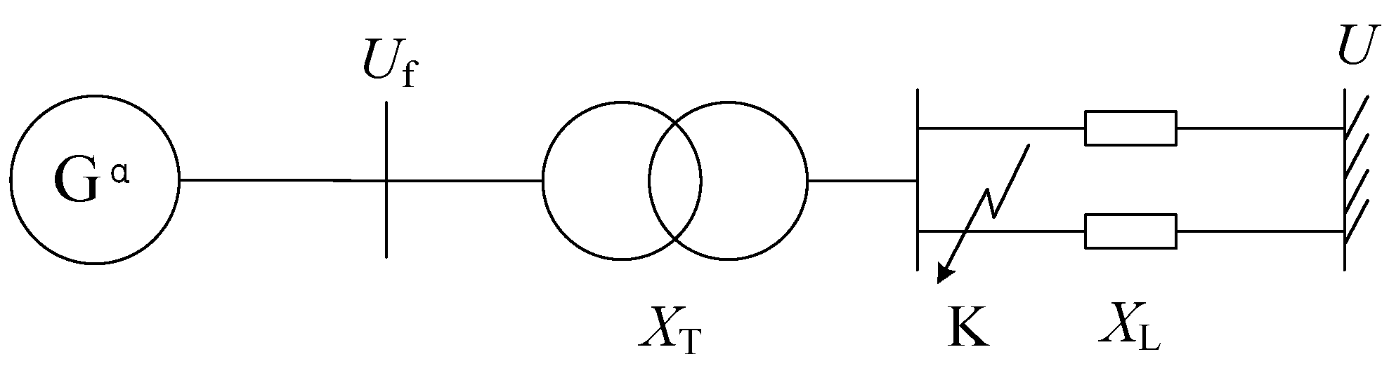
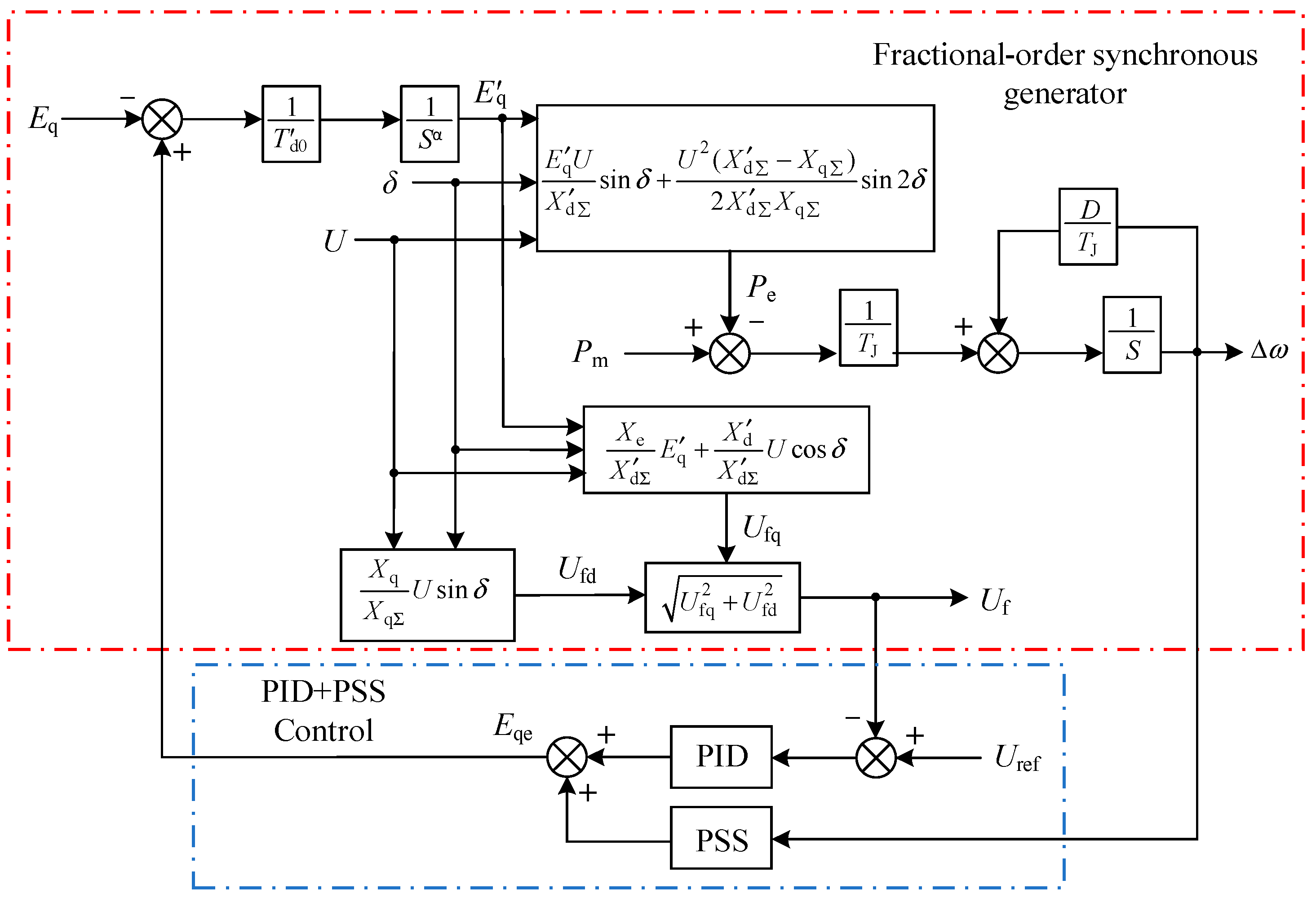
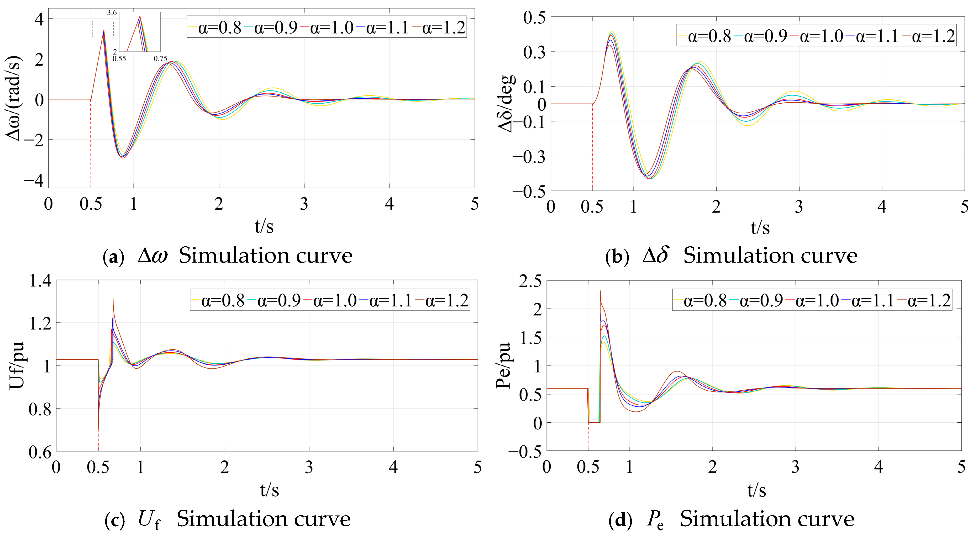
  • This paper establishes a single-machine infinite system that includes the 2 + α order synchronous generator model and PID+PSS excitation control. Based on this system, this paper investigates the dynamic operating characteristics of the 2 + α order synchronous generator model under three different disturbance conditions.
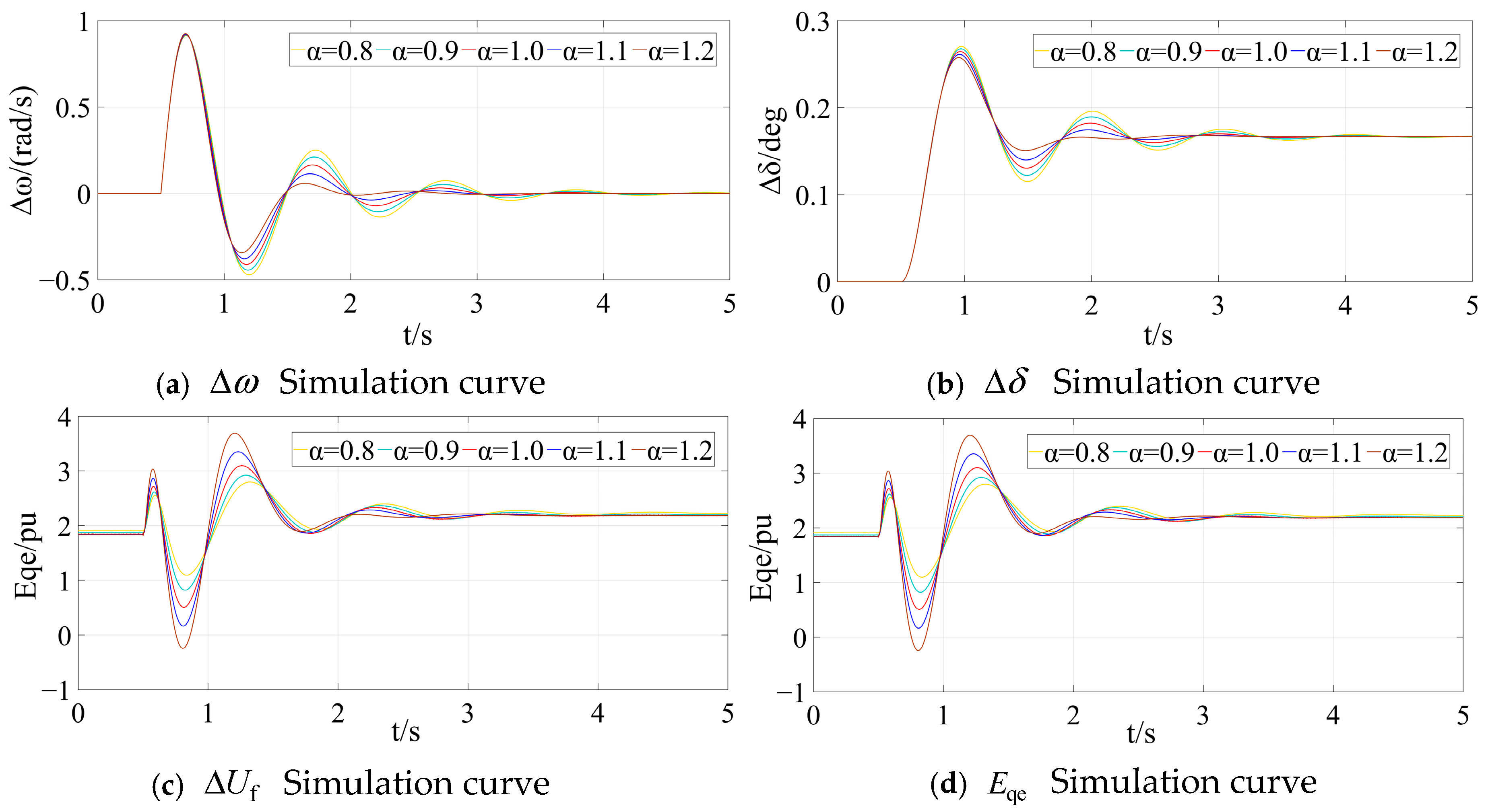
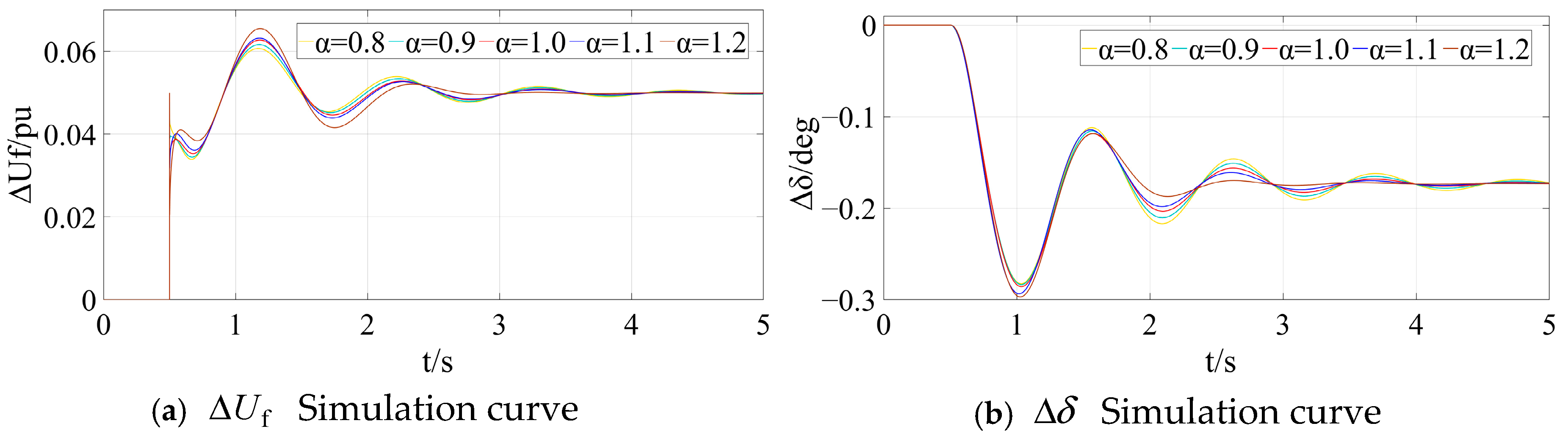
  • The digital simulations presented in this study reveal that higher-order generator inductance is more effective in mitigating mechanical oscillations, whereas lower-order inductance facilitates terminal voltage recovery and suppresses oscillations in electromagnetic power output.
The subsequent sections of this paper are structured as follows: Section 2 provides a concise introduction to the Caputo definition of fractional calculus and the concept of fractional inductance. Section 3 formulates the voltage equation for the fractional synchronous generator and develops the 2 + α order model of the fractional synchronous generator. In Section 4, the excitation control for the Automatic Voltage Regulator combined with the power system stabilizer is designed, alongside the single-machine infinite bus power system model. Section 5 presents digital simulations to evaluate the dynamic response characteristics of the 2 + α order model of the fractional synchronous generator under three distinct disturbance scenarios with varying inductance orders. Finally, Section 6 summarizes the conclusions and provides an outlook on the 2 + α order model of the fractional synchronous generator.

2. A Brief Introduction of Caputo Fractional Calculus and Fractional-Order Inductance

2.1. Definition of Fractional Calculus

Owing to the merits of the Caputo fractional calculus definition, including its minimal dependence on initial values, the facilitation of Laplace transformations, the property that the fractional derivative of constants is zero, and its computational simplicity, Caputo fractional calculus is extensively utilized in engineering research [7,18]. This paper will undertake an analytical study on the modeling of fractional-order synchronous generators employing the Caputo fractional calculus framework.
For the function y ( t ) , its Caputo fractional derivative is defined as follows [18]:
D t α t 0 C y ( t ) = 1 Γ ( m α ) t 0 t y m ( τ ) ( t τ ) 1 + α m d τ
where D is the fractional calculus operator; C denotes the Caputo derivative; α is the order of differentiation, α R + ; t is the independent variable; t 0 is the lower bound of the independent variable; Γ ( ) denotes the Gamma function; m = α .
Similarly, the Caputo fractional integral is defined as follows:
D t γ t 0 C y ( t ) = 1 Γ ( γ ) t 0 t y ( τ ) ( t τ ) 1 γ d τ
where γ is integral order, γ R + .

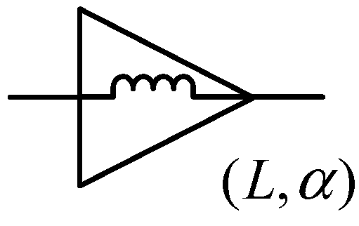
2.2. Fractional-Order Inductance

The fractional-order inductor is shown in Figure 1, where L is the inductance value, and α is the inductance order, 0 < α < 2 .
The mathematical model of the fractional-order inductor is given by the following:
L d α i L d t α = u L
where i L denotes the inductive current, and u L denotes the inductive voltage.

3. Fractional-Order Synchronous Generator Voltage Equation

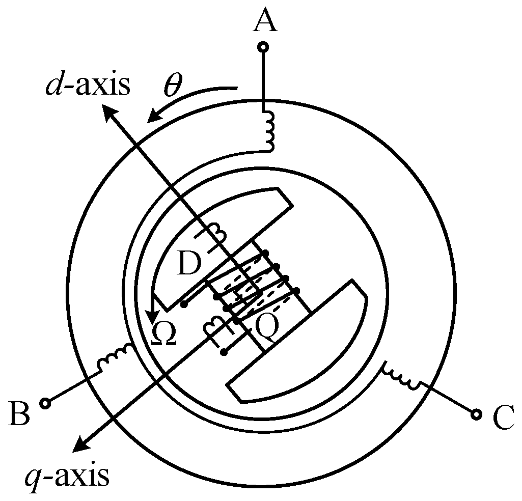
3.1. Establishing the Synchronous Generator Stator Voltage Equation in the Three-Phase Stationary Coordinate System (A-B-C)

In the derivation process presented in this paper, the synchronous generator is assumed to be an ideal machine characterized by a salient-pole rotor structure. Furthermore, unless explicitly stated otherwise, it is assumed that D (d-axis) and Q (q-axis) damping windings are present on the rotor, in addition to the field winding. The structure of the synchronous generator in the ABC coordinate system is shown in Figure 2.
In terms of defining the positive current direction, unless explicitly stated otherwise, the stator windings adhere to the generator convention. This implies that the output current is considered the positive current direction, and a positive current flowing through the stator phase windings results in a negative magnetic flux linkage. Conversely, the field and damping windings conform to the motor convention, where the input current is regarded as the positive current direction, and a positive current flowing through these windings generates a positive magnetic flux linkage. The winding circuit diagram and the direction of voltage and current of the synchronous generator are shown in Figure 3.
In Figure 3, u A , u B , and u C are the terminal voltages of each phase of the stator; i A , i B , and i C are the currents of each phase of the stator; R a , R b , and R c are the resistances of the three-phase windings of the stator; L aa , L bb , and L cc are the self-inductances of the three-phase windings of the stator; u f is the voltage applied to the excitation winding, and the damping winding is short-circuited, resulting in a terminal voltage of 0; i f , i D , and i Q are the currents of the excitation winding and the d-axis and q-axis damping windings, respectively; R f , R D , and R Q are the resistances of the excitation winding and the d-axis and q-axis damping windings, respectively. L ff , L DD , and L QQ are the self-inductances of the rotor excitation winding and damping winding, respectively.
In the three-phase stationary coordinate system (A-B-C), the voltage matrix of the stator three-phase windings of an integer-order synchronous generator can be expressed as follows:
u s = d ψ s d t R s i s
where u s is the voltage column matrix of the stator windings; ψ s is the flux linkage column matrix of the stator windings; R s is the resistance matrix of the stator; i s is the current column matrix of the stator windings. u s = u A u B u C T , i s = i A i B i C T , ψ s = ψ A ψ B ψ C T , R s = d i a g R a , R b , R c . ψ A , ψ B , and ψ C are the flux linkages of the stator windings for phases A, B, and C, respectively.
The voltage matrix of the excitation winding and the damping winding can be expressed as follows:
u r = d ψ r d t + R r i r
where u r is the voltage column matrix of the rotor winding; ψ r is the flux linkage column matrix of the rotor winding; R r is the resistance matrix of the rotor; i r is the current column matrix of the rotor winding. u r = u f 0 0 T , i r = i f i D i Q T , ψ r = ψ f ψ D ψ Q T , R r = d i a g R f , R D , R Q . ψ f , ψ D , and ψ Q denote the magnetic flux linkages of the rotor excitation winding and the d-axis and q-axis damper windings, respectively.
According to the formula theorem, the stator flux linkage matrix of a synchronous generator is defined as follows:
ψ s = L s i s + M sr i r
The rotor flux linkage matrix is defined as follows:
ψ r = M r s i s + L r i r
where L s is the self-inductance and mutual inductance matrix of the stator windings, M sr and M r s are the mutual inductance matrices between the stator and rotor windings, and L r is the self-inductance and mutual inductance matrix of the rotor windings.
In an ideal synchronous generator,
L s 2 = M s 2
where L s 2 is the amplitude of the second harmonic of the stator winding self-inductance, and M s 2 is the amplitude of the second harmonic of the stator winding mutual inductance.

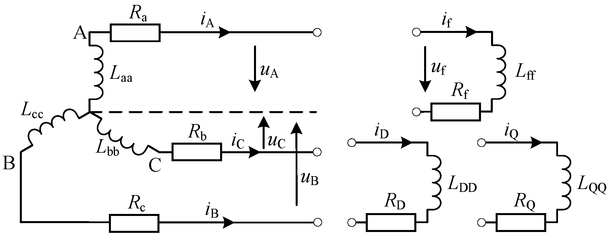
3.2. Establishing the Fractional-Order Synchronous Generator Stator Voltage Equation in the Three-Phase Stationary Coordinate System (A-B-C)

Figure 4a,b, respectively, show the structure diagram and winding circuit diagram of a synchronous generator considering fractional-order characteristics.
Substituting the fractional-order inductance mathematical model into (4), the stator voltage equation u s of the fractional-order synchronous generator in the three-phase stationary coordinate system can be obtained through the composite function chain transformation. Letting the inductance order of the stator be α and the inductance order of the rotor be β , 0 < α , β < 2 , the following expression can be derived:
u s = d L s d t i s L s d α i s d t α + d M sr d t i r + M sr d β i r d t β R s i s

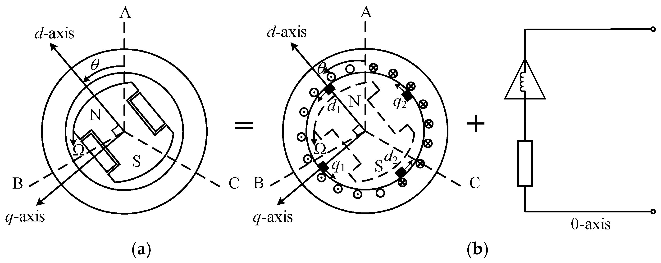
3.3. Establishing the Fractional-Order Synchronous Generator Stator Voltage Equation in the Synchronous Rotating Coordinate System (d-q-0)

dq0 transformation is a transformation from a stationary axis to a rotating axis that rotates together with the rotor. Physically speaking, the dq0 transformation is equivalent to transforming the three-phase winding of the stator into a commutator winding. The commutator is equipped with two sets of brushes that rotate together with the salient-pole rotor, one set coinciding with the d-axis and the other set coinciding with the q-axis. In addition, there is an isolated 0-axis system, as shown in Figure 5.
The transformation matrix from the three-phase stationary coordinate system to the two-phase rotating coordinate system (Park’s Transformation) is C dq 0 , while the inverse transformation matrix is C dq 0 1 .
C dq 0 = cos θ sin θ 1 cos θ 2 π 3 sin θ 2 π 3 1 cos θ + 2 π 3 sin θ + 2 π 3 1 ,   C dq 0 1 = 2 3 cos θ cos θ 2 π 3 cos θ + 2 π 3 sin θ sin θ 2 π 3 sin θ + 2 π 3 1 2 1 2 1 2 .
According to Park’s Transformation principle, the following coordinate transformation relationship can be obtained:
u s = C dq 0 u dq 0   i s = C dq 0 i dq 0
where u dq 0 = u d u q u 0 T , i dq 0 = i d i q i 0 T . u dq 0 and i dq 0 denote the fractional-order voltage and current of the synchronous generator stator obtained after Park’s Transformation. u d ,   u q , and u 0 are the d-axis component, q-axis component, and 0-axis component of the stator voltage, respectively. A, B, and C are also the d-axis component, q-axis component, and 0-axis component of the stator current, respectively.
From Equation (1) of the coordinate transformation relation (10), the stator voltage equation of a fractional-order synchronous generator in a synchronous rotating coordinate system can be expressed as follows:
u dq 0 = C dq 0 1 u s
According to (9) and Equation (2) in (10), (11) has the following form:
u dq 0 = C dq 0 1 d L s d θ ω C dq 0 i dq 0 C dq 0 1 L s d α C dq 0 d t α i dq 0 C dq 0 1 L s C dq 0 d α i dq 0 d t α + C dq 0 1 d M sr d θ ω i r + C dq 0 1 M sr d β i r d t β C dq 0 1 R s C dq 0 i dq 0
where θ is the angle between the rotor’s d-axis and the stator’s A-phase axis; ω is the angular velocity of the rotor, ω = d θ d t ; C dq 0 1 d L s d θ ω C dq 0 i dq 0 is the rotational voltage; C dq 0 1 L s d α C dq 0 d t α i dq 0 is the fractional-order Christopher voltage; C dq 0 1 L s C dq 0 d α i dq 0 d t α is the fractional-order inductive voltage drop; C dq 0 1 d M sr d θ ω i r is the motion mutual inductance voltage between the rotor and the stator; C dq 0 1 M sr d β i r d t β is the fractional-order mutual inductance voltage between the rotor and the stator; C dq 0 1 R s C dq 0 i dq 0 is the stator resistance voltage.
According to the rotational voltage and the motion mutual inductance voltage between the rotor and the stator, d L s d θ and d M sr d θ can be expressed as follows:
d L s d θ = 2 L s 2 sin 2 θ 2 M s 2 sin 2 θ 2 π 3 2 M s 2 sin 2 θ + 2 π 3 2 M s 2 sin 2 θ 2 π 3 2 L s 2 sin 2 θ + 2 π 3 2 M s 2 sin 2 θ 2 M s 2 sin 2 θ + 2 π 3 2 M s 2 sin 2 θ 2 L s 2 sin 2 θ 2 π 3 ,
d M sr d θ = M af sin θ M aD sin θ M aQ cos θ M af sin θ 2 π 3 M aD sin θ 2 π 3 M aQ cos θ 2 π 3 M af sin θ + 2 π 3 M aD sin θ + 2 π 3 M aQ cos θ + 2 π 3 .
For d M sr d θ , M af and M aD denote the magnitudes of mutual inductance between one phase winding of the stator and the excitation winding and the d-axis damping winding, respectively; M aQ is the magnitude of mutual inductance between one phase winding of the stator and the q-axis damping winding.
Based on the definition of Caputo fractional derivatives, when 0 < α < 2 , there is the following:
d α C dq 0 d t α = ω α cos ( θ + π α 2 ) sin ( θ + π α 2 ) 0 cos ( θ 2 π 3 + π α 2 ) sin ( θ 2 π 3 + π α 2 ) 0 cos ( θ + 2 π 3 + π α 2 ) sin ( θ + 2 π 3 + π α 2 ) 0
Combining Park’s Transformation, d L s d θ , d M sr d θ , and (13), the stator voltage matrix of the fractional-order synchronous generator in the dq0 coordinate system can be derived as follows:
u d u q u 0 = ω α L s 0 cos π α 2 + M s 0 cos π α 2 + 3 2 L s 2 cos π α 2 ω α L s 0 sin π α 2 M s 0 sin π α 2 3 2 L s 2 sin π α 2 + 3 ω L s 2 0 ω α L s 0 sin π α 2 + M s 0 sin π α 2 3 2 L s 2 sin π α 2 + 3 ω L s 2 ω α L s 0 cos π α 2 + M s 0 cos π α 2 3 2 L s 2 cos π α 2 0 0 0 0 i d i q i 0 + L s 0 + M s 0 + 3 2 L s 2 0 0 0 L s 0 + M s 0 3 2 L s 2 0 0 0 L s 0 2 M s 0 d α i d d t α d α i q d t α d α i 0 d t α + R a 0 0 0 R a 0 0 0 R a i d i q i 0 + M af M aD 0 0 0 M aQ 0 0 0 d β i f d t β d β i D d t β d β i Q d t β + 0 0 ω M aQ ω M af ω M aD 0 0 0 0 i f i D i Q

3.4. Establishing the Fractional-Order Synchronous Generator Rotor Voltage Equation in the Synchronous Rotating Coordinate System (d-q-0)

To establish the fractional-order synchronous generator rotor voltage equation, it is necessary to first obtain the synchronous generator rotor voltage equation. By substituting (7) into (5), the synchronous generator rotor voltage equation can be expressed as follows:
u r = d M r s i s d t + d L r i r d t + R r i r
According to the chain rule for differentiating composite functions, (15) can be further expressed as follows:
u r = d M r s d t i s M r s d i s d t + d L r d t i r + L r d i r d t + R r i r
Based on (3), the fractional-order inductance mathematical model of the rotor can be expressed as follows:
L d β i L d t β = u L
By introducing the fractional-order inductance model of the stator and rotor, the fractional-order synchronous generator rotor voltage equation can be expressed as follows:
u r = d M r s d t i s M r s d α i s d t α + d L r d t i r + L r d β i r d t β + R r i r
After introducing Park’s Transformation into the stator fractional-order voltage equation, the fractional-order synchronous generator rotor voltage equation in the synchronous rotating coordinate system (d-q-0) can be expressed as follows:
u r 1 = d M r s d t C dq 0 i dq 0 M r s d α C dq 0 i dq 0 d t α + d L r d t i r + L r d β i r d t β + R r i r
where u r 1 is the rotor voltage of the fractional-order synchronous generator in the synchronous rotating coordinate system (d-q-0), u r 1 = u f 0 0 T . u f is the excitation voltage after Park’s Transformation. The damping winding remains short-circuited, and the terminal voltage is 0. Assuming that, after introducing Park’s Transformation, the rotor current is i r , since the rotor current is not transformed, i r = i r , which means i r = i r = i f i D i Q T .
After further derivation of (19), it has the following form:
u r 1 = d M r s d θ ω C dq 0 i dq 0 M r s d α C dq 0 d t α i dq 0 M r s C dq 0 d α i dq 0 d t α + L r d β i r d t β + R r i r
where d M r s d θ ω C dq 0 i dq 0 is the motion-induced mutual inductance voltage from the stator to the rotor; M r s d α C dq 0 d t α i dq 0 is the fractional-order time-varying mutual inductance voltage from the stator to the rotor; M r s C dq 0 d α i dq 0 d t α is the fractional-order mutual inductance voltage from the stator to the rotor; L r d β i r d t β is the fractional-order inductance voltage of the rotor; R r i r is the rotor resistance voltage.
According to the motion-induced mutual inductance voltage from the stator to the rotor, d M r s d θ can be expressed as follows:
d M r s d θ = M af sin θ M af sin θ 2 π 3 M af sin θ + 2 π 3 M aD sin θ M aD sin θ 2 π 3 M aD sin θ + 2 π 3 M aQ cos θ M aQ cos θ 2 π 3 M aQ cos θ + 2 π 3 .
Combining Park’s Transformation and d M r s d θ , the matrix form of (20) can be expressed as follows:
u f 0 0 = 3 2 ω α M af cos π α 2 3 2 M af ω ω α sin π α 2 0 3 2 ω α M aD cos π α 2 3 2 M aD ω ω α sin π α 2 0 3 2 M aQ ω α sin π α 2 ω 3 2 ω α M aQ cos π α 2 0 i d i q i 0 + 3 2 M af 0 0 3 2 M aD 0 0 0 3 2 M aQ 0 d α i d d t α d α i q d t α d α i 0 d t α + L ff M fD 0 M Df L DD 0 0 0 L QQ d β i f d t β d β i D d t β d β i Q d t β + R f 0 0 0 R D 0 0 0 R Q i f i D i Q
Based on the fractional-order voltage matrices of the stator and rotor, the voltage equations for the fractional-order synchronous generator can be derived as follows:
u d = ω α L s 0 cos π α 2 + M s 0 cos π α 2 + 3 2 L s 2 cos π α 2 + R a i d L s 0 + M s 0 + 3 2 L s 2 d α i d d t α ω α L s 0 sin π α 2 M s 0 sin π α 2 3 2 L s 2 sin π α 2 + 3 ω L s 2 i q + M af d β i f d t β + M aD d β i D d t β ω M aQ i Q u q = ω α L s 0 sin π α 2 + M s 0 sin π α 2 3 2 L s 2 sin π α 2 + 3 ω L s 2 i d ω α L s 0 cos π α 2 + M s 0 cos π α 2 3 2 L s 2 cos π α 2 + R a i q L s 0 + M s 0 3 2 L s 2 d α i q d t α + ω M af i f + ω M aD i D + M aQ d β i Q d t β u 0 = L s 0 2 M s 0 d α i 0 d t α R a i 0 u f = 3 2 ω α M af cos π α 2 i d 3 2 M af ω ω α sin π α 2 i q 3 2 M af d α i d d t α + R f i f + L ff d β i f d t β + M fD d β i D d t β 0 = 3 2 ω α M aD cos π α 2 i d 3 2 M aD ω ω α sin π α 2 i q 3 2 M aD d α i d d t α + R D i D + M Df d β i f d t β + L DD d β i D d t β 0 = 3 2 M aQ ω α sin π α 2 ω i d 3 2 ω α M aQ cos π α 2 i q 3 2 M aQ d α i q d t α + L QQ d β i Q d t β + R Q i Q

3.5. Fractional-Order Synchronous Generator 2 + α Order Model

In practical power system dynamic analysis, when considering the dynamics of the excitation system, the simplest model is the third-order model, which is more suitable for salient-pole synchronous generators. The fractional-order synchronous generator model proposed in this paper is derived based on the third-order integer-order synchronous generator model, with its derivation principles and simplifications referencing the third-order model. For convenience in discussion, this model is referred to in this paper as the fractional-order synchronous generator 2 + α order model.
The derivation of the 2 + α order model of the fractional-order synchronous generator is based on the following assumptions:
(1)
Ignore the transients of the stator d and q windings and set d α ψ d / d t α = d α ψ q / d t α = 0 in the stator voltage equation.
(2)
In the stator voltage equation, assuming ω 1 p . u . , during transient processes where speed changes are small, the error caused by ω is negligible.
(3)
Ignore the D winding and Q winding, as their effects can be approximately considered by adding damping terms to the rotor motion equation.
The derivation of the fractional-order synchronous generator model of order 2 + α is initiated as follows. Initially, the per-unit normalization of the voltage and flux linkage equations for the fractional-order synchronous generator is conducted. Nevertheless, when simultaneously considering both the fractional order of the stator and the rotor, the per-unit normalization becomes exceedingly intricate, which hinders subsequent analysis and computations. Consequently, this paper exclusively examines the influence of the α-order within the fractional-order generator model, thereby significantly reducing the parameter preparation workload and simplifying the analytical process. By disregarding the transient state of the stator winding and assuming the absence of cross-axis components, and with the selection of appropriate base values, the fractional-order voltage equations of the synchronous generator in the dq0 coordinate system can be expressed in per-unit form as follows:
u d = d α ψ d d t α sin π α 2 ω α ψ q R a i d u q = d α ψ q d t α + sin π α 2 ω α ψ d R a i q u 0 = d α ψ 0 d t α R a i 0 ,   u f = d α ψ f d t α + R f i f u D = d α ψ D d t α + R D i D u Q = d α ψ Q d t α R Q i Q
The flux linkage equation in Park’s Transformation does not involve a differentiation process, meaning that the integer-order flux linkage equation remains consistent before and after Park’s Transformation. The magnetic flux equation in per-unit value form within the dq0 coordinate system can be expressed as follows (the per-unit value “*” symbol is omitted in the following equation and all subsequent equations):
ψ d ψ q ψ 0 ψ f ψ D ψ Q = X d 0 0 X ad X ad 0 0 X q 0 0 0 X aq 0 0 X 0 0 0 0 X ad 0 0 X ff M fD 0 X ad 0 0 M Df X DD 0 0 X aq 0 0 0 X QQ i d i q i 0 i f i D i Q
where X d , X q , and X 0 denote the synchronous reactances for the d-axis, q-axis, and 0-axis, respectively. X ad and X aq denote the armature reaction reactances for the d-axis and q-axis. M fD and M Df denote the mutual inductances between the field winding and the d-axis damper winding. Additionally, L ff ,   L DD ,   L QQ ,   M fD ,   M Df are distinct constant values.
According to the definition of magnetic flux linkage, ψ d and ψ q have the following form:
ψ d = E q X d i d ψ q = X q i q
where E q is the transient electromotive force of the synchronous generator, and X d is the d-axis transient reactance.
Substituting d α ψ d d t α = d α ψ q d t α = 0 , ω 1 , and (25) into (23) to eliminate ψ d and ψ q , the result can be derived as follows:
u d = sin π α 2 X q i q R a i d u q = sin π α 2 E q X d i d R a i q
The voltage equation of the rotor excitation winding in (23) can be rewritten as follows:
d α ψ f d t α = u f R f i f
By multiplying both sides of (27) by X ad X f × X f R f , it can be further derived as follows:
d α ψ f X ad X f d t α X f R f = X ad u f X f X f R f X ad i f
where X f denotes the d-axis operational reactance.
The equivalent practical variables on the stator side are as follows:
T d 0 = X f R f ,   E qe = X ad u f R f ,   E q = X ad i f ,   E q = X ad X f ψ f
where E q is the no-load electromotive force; E qe is the excitation electromotive force; T d 0 denotes the excitation winding time constant when the stator is open-circuit.
Substituting the equations in (29) into (28), the transient equation of the fractional-order rotor excitation winding can be derived as follows:
d α E q d t α = 1 T d 0 E qe E q
The 2 + α order model of fractional-order synchronous generator also includes the following rotor motion equation, and its derivation process will not be repeated in this paper:
T J d ω d t = P m P e D ω ω 0 d δ d t = ω ω 0
where T J is the rotor inertia time constant; P m is the mechanical output power of the prime mover, P m = T m ω . P e is the electromagnetic output power of the synchronous motor, P e = T e ω . D denotes the damping coefficient of the synchronous motor, and ω 0 denotes the synchronous angular velocity of the synchronous generator rotor.
In summary, the fractional-order synchronous generator 2 + α order model composed of (26), (30), and (31) can be expressed as follows:
u d = sin π α 2 X q i q R a i d u q = sin π α 2 E q X d i d R a i q ,   d α E q d t α = 1 T d 0 E qe E q T J d ω d t = P m P e D ω ω 0 d δ d t = ω ω 0

4. Mathematical Model of a Fractional-Order Excitation Control System for Synchronous Generators

4.1. Single-Machine Infinite Bus Power System Model

In engineering, the single-machine infinite bus power system model, depicted in Figure 6, is frequently utilized to analyze generator control issues [19,20]. In a single-machine infinite bus system, the generator employs a third-order practical model to account for the dynamics of the excitation system and the salient-pole effects of the generator. The model neglects the resistance of the generator stator, transformer, and transmission lines, while assuming the excitation power system as a fast excitation system.
In Figure 6, G α is the fractional-order synchronous generator, U f is the terminal voltage of the synchronous generator, X T is the transformer reactance, K is the fault point, X L is the line reactance, and U is the infinite bus voltage.
The fractional-order synchronous generator control system model shown in Figure 6 can be described by the following fractional-order rotor motion differential equation:
d α E q / d t α d δ / d t d ω / d t = E q / T d 0 ω ω 0 ( ω 0 P e D ( ω ω 0 ) ) / T J + 1 / T d 0 0 0 E qe + 0 0 ω 0 / T J P m
where E q , δ , and ω denote the state variables, while E qe is a control variable. P m denotes another control variable of the generator; however, when focusing solely on the excitation control of the generator, it is considered a disturbance within the excitation control system. Except for δ , which has units of radians (rad), ω , which has units of radians per second (rad/s), and the time constant with units of seconds (s), all other values are expressed in per-unit form.
The relationship between the state quantities in (33) and U f and P e can be expressed as follows:
U f = U fq 2 + U fd 2 U fd = X q X q Σ U sin δ U fq = X e X d Σ E q + X d X d Σ U cos δ P e = E q U X d Σ sin δ + U 2 ( X d Σ X q Σ ) 2 X d Σ X q Σ sin 2 δ
where X e = X T + X L / 2 is the total equivalent reactance of the transformer and transmission line, X d Σ = X d + X e , and X q Σ = X q + X e . Based on expressions (33) and (34), the following fractional-order synchronous generator control strategy can be obtained (Figure 7).

4.2. PID + PSS Excitation Control Design

Currently, in practical applications, the most widely used method for controlling the excitation voltage of synchronous generators is a combination of Automatic Voltage Regulator (AVR) and power system stabilizer (PSS) [21]. The excitation system is shown in Figure 8.
Common AVR control strategies include four methods: PID control, linear optimal control, adaptive control, and nonlinear excitation control. This paper uses PID control theory to study fractional-order synchronous motor excitation control.
IEEE has specified the mathematical model of PSS [22,23], and this paper uses the PSS 2A-type power system stabilizer to design the excitation auxiliary module for excitation control simulation.

5. Digit Simulation and Analysis

To study the dynamic operating characteristics of the fractional-order synchronous generator 2 + α order model, this paper sets up three different simulation schemes.
Simulation Scheme I: Input mechanical power Δ P m = 20 % disturbance. Investigate the effect of mechanical power changes on terminal voltage for the fractional-order synchronous generator 2 + α order model under different inductance orders.
Simulation Scheme II: Excitation regulator reference voltage Δ U ft = 5 % disturbance. Examine the tracking ability of the generator terminal voltage to reference voltage changes for the fractional-order synchronous generator 2 + α order motor model under different inductance orders.
Simulation Scheme III: Generator high-voltage sideline short-circuit disturbance. Study the recovery speed of the fractional-order synchronous generator 2 + α order model with different inductance orders under severe large disturbance conditions.
This paper utilizes the MATLAB/Simulink simulation platform, employing the high-precision Caputo operator and the Oustaloup filter principle from the FOTF toolbox to develop fractional-order inductance simulation components and to construct a fractional-order synchronous generator model of order 2 + α. The excitation control strategy implemented for the 2 + α order single-machine infinite bus system model is the PID+PSS excitation control. The parameters of the model are detailed in Table 1.

5.1. Simulation Scheme I

This condition involves a disturbance with an input mechanical power of Δ P m = 20 % . The initial value of the input mechanical power is 0.6, and the final value is 0.8, with the disturbance occurring at 0.5 s. The inductance order of the fractional-order synchronous generator 2 + α model is set sequentially to 0.8, 0.9, 1.0, 1.1, and 1.2. The response process curves of the system’s state variables Δ ω , Δ δ , Δ U f , and E qe are shown in Figure 9a–d.
From Figure 9a,b, it can be observed that as the fractional-order inductance α increases from 0.8 to 1.2, the oscillations of Δ ω and Δ δ progressively diminish, with the number of oscillations decreasing from 3 to 1 and 2, respectively. At t = 3 s, the Δ ω and Δ δ curves corresponding to α = 1.2 nearly stabilize and approach steady-state behavior.
From Figure 9c, it can be observed that an increase in the inductance order does not influence the terminal voltage’s behavior at a specific point. Following a disturbance at 0.5 s, the terminal voltage, Δ U f , stabilizes to approximately zero after about 5 s, signifying the absence of a steady-state error. While an increase in order diminishes the frequency of oscillations in Δ U f and reduces the amplitude of each oscillation, the overall impact remains negligible.
From Figure 9d and Table 2, it can be observed that as the fractional-order inductance α increases from 0.8 to 1.2, the steady-state error of E qe remains virtually unchanged, while the overshoot increases from 0.249% to 0.689%, the response time rises from 0.825 s to 1.362 s, and the maximum peak value escalates from 2.797 pu to 3.692 pu.
The preceding analysis indicates that as the order of inductance progressively increases, the speed and power angle of the synchronous generator’s terminal voltage more readily achieves a stable state. Consequently, the oscillation frequency and amplitude of Δ ω and Δ δ are more effectively regulated. Furthermore, variations in the inductance order do not ultimately influence the control outcome of Δ U f ; however, higher-order inductance accelerates the adjustment process of Δ U f , enabling it to revert to its initial state more expeditiously. In contrast, E qe exhibits a unique behavior compared to the other three states with increasing inductance. Its initial value deviation consistently rises, yet its steady-state value and convergence speed remain largely unchanged. It can be observed that although an increase in inductance alters the amplitude of E qe , it does not compromise the adjustment capability of the excitation control system.

5.2. Simulation Scheme II

This condition involves a disturbance in the excitation regulator reference voltage Δ U ft   =   5 % . The initial value of the terminal voltage is 1.0293, and the final value is 1.0793, with the disturbance occurring at 0.5 s. The inductance order of the fractional-order synchronous generator 2 + α model is sequentially set to 0.8, 0.9, 1.0, 1.1, and 1.2. The response process curves of the system’s relevant state variables Δ U f and Δ δ are shown in Figure 10a,b.
From Figure 10a, it can be observed that as the inductance order α increases from 0.8 to 1.1, the dynamic response process of Δ U f changes little. When α reaches 1.2, the deviation in terminal voltage is relatively larger compared to before the order of 1.1. However, the settling time of the waveform decreases from 4.5 s to 3 s.
From Figure 10b, it can be observed that as the inductance order α increases from 0.8 to 1.2, the oscillation frequency of Δ δ gradually decreases, and the time for the waveform to reach a stable state advances from the 5th second to around the 3rd second.
The preceding analysis indicates that changes in the inductance order α have little impact on the process of terminal voltage Δ U f deviation adjustment. The ability of the terminal voltage to track the set value remains almost unchanged at each order, and the dynamic response effect is similar for each order. As the order α gradually increases, the power angle difference Δ δ not only reduces the amplitude of the power angle oscillation of the fractional-order synchronous generator but also allows the power angle oscillation to stabilize more quickly. It is apparent that higher orders can enhance power angle stability.

5.3. Simulation Scheme III

This condition involves a short-circuit disturbance on the high-voltage side of a fractional-order synchronous motor. The short-circuit point is cleared and reclosed at 0.5 s. The response process curves of the system’s related state variables Δ δ , Δ ω , U f , and P e are shown in Figure 11a–d.
From Figure 11a,b, it can be observed that as the inductance order α increases from 0.8 to 1.2, the time for Δ ω and Δ δ to stabilize gradually advances. At the 3rd second, the Δ ω and Δ δ curves for an order α of 1.2 are almost stable.
From Figure 11c,d and Table 3, it can be observed that as the fractional-order inductance increases, both the terminal voltage U f and the output electromagnetic power P e exhibit zero steady-state error. The overshoots of U f and P e rise from 0.063% and 1.362% to 0.276% and 2.872%, respectively. Meanwhile, the response time of U f increases from 1.000 s to 1.580 s, whereas that of P e decreases significantly from 4.532 s to 2.455 s.
The preceding analysis demonstrates that although different inductance orders affect the transient process of the fractional-order synchronous generator, it remains within the control limits. Figure 11a,b indicate that the unit can still suppress mechanical oscillations, and the suppression effect is almost unaffected by the inductance order. Figure 11c,d, and Table 3 reveal that under conditions of significant disturbances, the recovery speed of the terminal voltage U f and the output electromagnetic power P e are influenced by the inductance order. For U f , a higher inductance order correlates with a deceleration in system response and recovery speed. In contrast, as the inductance order increases, the response and recovery speeds of P are enhanced.

6. Conclusions

This paper is based on the theory of fractional calculus, considering the fractional-order characteristics of winding inductance. Employing a mechanistic modeling approach, it first derives the voltage equations of fractional-order synchronous generators in both the three-phase stationary coordinate system (A-B-C) and the synchronous rotating coordinate system (d-q-0). Subsequently, through necessary simplifications and deductions, this study formulates the fractional-order synchronous generator model of order 2 + α. To investigate the fractional-order dynamic characteristics of this model, this study conducted simulation experiments The results revealed that when the fractional-order parameter 1.2 > α ≥ 1, the oscillation amplitude and frequency of system state variables Δ ω and Δ δ decreased significantly, accompanied by an earlier stabilization time. This demonstrates enhanced capability of the generator to suppress mechanical oscillations. When the fractional-order parameter 1 > α > 0.8, the response time of system state variables E qe and U f became faster with reduced overshoot, indicating improved excitation control effectiveness of the generator and accelerated disturbance recovery speed.
Proposed further research work is as follows:
(1) This paper utilizes the conventional PID+PSS excitation control approach. By adopting the FOPID+FOPSS excitation control method, which offers superior dynamic control performance and robustness [24], the fractional-order synchronous generator can significantly improve its voltage stability and resistance to interference.
(2) The precision of the synchronous generator model is paramount for advancing pertinent research. This paper exclusively examines the impact of the stator α order in the formulation of the fractional-order synchronous generator model. Subsequent investigations will incorporate an analysis of the rotor β order to assess the combined effects of the stator α and rotor β inductance orders on the performance characteristics of fractional-order synchronous generators.

Author Contributions

Conceptualization, J.X.; Methodology, J.X., Z.G. and S.T.; Software, J.X. and S.T.; Validation, S.T. and C.W.; Formal analysis, J.X., Z.G., X.L. and Y.L.; Investigation, C.W.; Resources, X.L. and Y.L.; Data curation, Z.G., X.L. and C.W.; Writing—original draft, Z.G.; Writing—review & editing, J.X., Z.G. and X.L.; Funding acquisition, J.X. All authors have read and agreed to the published version of the manuscript.

Funding

This research received no external funding.

Data Availability Statement

Data is contained within the article.

Conflicts of Interest

The authors declare no conflict of interest.

References

  1. Podlubny, I. Fractional-Order Systems and Fractional-Order Controllers; Academic: New York, NY, USA, 1994. [Google Scholar]
  2. Hilfer, R. Applications of fractional calculus in physics. In Applications of Fractional Calculus in Physics; World Scientific: Singapore, 2000; pp. 87–130. [Google Scholar]
  3. Djordjevic, V.D.; Atanackovic, T.M. On the application of fractional calculus in mechanics. In Proceedings of the 1st Serbian Congress on Theoretical and Applied Mechanics, Belgrade, Serbia, 10–13 April 2007; pp. 1–10. [Google Scholar]
  4. Kimeu, J.M. Fractional Calculus: Definitions and Applications. Master’s Thesis, Department of Mathematics, Western Kentucky University, Bowling Green, KY, USA, 2009. [Google Scholar]
  5. Baleanu, D.; Günvenc, Z.B.; Machado, J.A.T. New Trends in Nanotechnology and Fractional Calculus Applications; Springer: Berlin, Germany, 2010. [Google Scholar]
  6. Zahra, W.K.; Hikal, M.M.; Bahnasy, T.A. Solutions of fractional order electrical circuits via Laplace transform and nonstandard finite difference method. J. Egypt. Math. Soc. 2017, 25, 252–261. [Google Scholar] [CrossRef]
  7. Podlubny, I. Fractional Differential Equations; Academic: New York, NY, USA, 1999. [Google Scholar]
  8. Zhou, Y.; Xu, G.; Huang, Y. Experiment analysis on motor-generator pair system for providing inertia of renewable energy. In Proceedings of the 21st International Conference on Electrical Machines and Systems (ICEMS), Jeju, Republic of Korea, 7–10 October 2018; pp. 1–6. [Google Scholar]
  9. Allagui, A.; Freeborn, T.J.; Elwakil, A.S.; Fouda, M.E.; Maundy, B.J.; Radwan, A.G.; Said, Z.; Abdelkareem, M.A. Review of fractional-order electrical characterization of supercapacitors. J. Power Sources 2018, 400, 457–467. [Google Scholar] [CrossRef]
  10. Chen, X.; Xi, L.; Zhang, Y.; Ma, H.; Huang, Y.; Chen, Y. Fractional techniques to characterize non-solid aluminum electrolytic capacitors for power electronic applications. Nonlinear Dyn. 2019, 98, 3125–3141. [Google Scholar] [CrossRef]
  11. Elwakil, A.S.; Allagui, A.; Freeborn, T.J.; Maundy, B.J. Further experimental evidence of the fractional-order energy equation in supercapacitors. AEU-Int. J. Electron. Commun. 2017, 78, 209–212. [Google Scholar] [CrossRef]
  12. Tessarolo, A. Accurate computation of multiphase synchronous machine inductances based on winding function theory. IEEE Trans. Energy Convers. 2012, 27, 895–904. [Google Scholar] [CrossRef]
  13. Niu, H.; Liu, L.; Jin, D.; Liu, S. High-tracking-precision sensorless control of PMSM system based on fractional order model reference adaptation. Fractal Fract. 2023, 7, 21. [Google Scholar] [CrossRef]
  14. Luo, S.; Song, Y.; Lewis, F.L.; Garrappa, R.; Li, S. Dynamic analysis and fuzzy fixed-time optimal synchronization control of unidirectionally coupled FO permanent magnet synchronous generator system. IEEE Trans. Fuzzy Syst. 2023, 31, 1742–1755. [Google Scholar] [CrossRef]
  15. Narayanan, G.; Ali, M.S.; Joo, Y.H.; Perumal, R.; Ahmad, B.; Alsulami, H. Robust adaptive fractional sliding-mode controller design for Mittag-Leffler synchronization of fractional-order PMSG-based wind turbine system. IEEE Trans. Syst. Man Cybern. Syst. 2023, 53, 7646–7655. [Google Scholar] [CrossRef]
  16. Anbalagan, P.; Joo, Y.H. Stabilization analysis of fractional-order nonlinear permanent magnet synchronous motor model via interval type-2 fuzzy memory-based fault-tolerant control scheme. ISA Trans. 2023, 142, 310–324. [Google Scholar] [CrossRef] [PubMed]
  17. Luo, S.; Jian, Y.; Gao, Q. Synchronous generator modeling and semi-physical simulation. In Proceedings of the 22nd International Conference on Electrical Machines and Systems (ICEMS), Harbin, China, 11–14 August 2019; pp. 1–6. [Google Scholar]
  18. Retière, N.M.; Ivanes, M.S. An introduction to electric machine modeling by systems of noninteger order. Application to double-cage induction machine. IEEE Trans. Energy Convers. 1999, 14, 1026–1032. [Google Scholar] [CrossRef]
  19. Sambariya, D.K.; Prasad, R. Robust power system stabilizer design for single machine infinite bus system with different membership functions for fuzzy logic controller. In Proceedings of the 7th International Conference on Intelligent Systems and Control (ISCO), Coimbatore, India, 4–5 January 2013; pp. 1–6. [Google Scholar]
  20. Abubakr, H.; Vasquez, J.C.; Mahmoud, K.; Darwish, M.M.F.; Guerrero, J.M. Robust PID-PSS design for stability improvement of grid-tied hydroturbine generator. In Proceedings of the 22nd International Middle East Power Systems Conference (MEPCON), Assiut, Egypt, 14–16 December 2021; pp. 1–6. [Google Scholar]
  21. Xue, D.Y. Fractional Calculus and Fractional-Order Control; Science Press: Beijing, China, 2018. [Google Scholar]
  22. IEEE Standard 421.5-2016; IEEE Recommended Practice for Excitation System Models for Power System Stability Studies. IEEE: Piscataway, NJ, USA, 2016.
  23. Kundur, P.; Paserba, J.; Ajjarapu, V.; Andersson, G.; Bose, A.; Canizares, C.; Hatziargyriou, N.; Hill, D.; Stankovic, A.; Taylor, C.; et al. Definition and classification of power system stability. IEEE Trans. Power Syst. 2004, 19, 1387–1401. [Google Scholar]
  24. Sarkar, D.U.; Prakash, T.; Singh, S.N. Fractional order PID-PSS design using hybrid deep learning approach for damping power system oscillations. IEEE Trans. Power Syst. 2025, 40, 543–555. [Google Scholar] [CrossRef]
Figure 1. Fractional inductor.
Fractalfract 09 00244 g001
Figure 2. Structure of synchronous generator.
Fractalfract 09 00244 g002
Figure 3. Winding circuit diagram and the direction of voltage and current of the synchronous generator.
Fractalfract 09 00244 g003
Figure 4. (a) Structural diagram of fractional-order synchronous generator. (b) Fractional-order winding circuit diagram.
Fractalfract 09 00244 g004
Figure 5. The meaning of dq0 transformation. (a) ABC coordinate system. (b) A dq coordinate system rotating with the rotor and an isolated 0-axis system.
Fractalfract 09 00244 g005
Figure 6. Single-machine infinite bus power system.
Fractalfract 09 00244 g006
Figure 7. Fractional-order synchronous generator control strategy.
Fractalfract 09 00244 g007
Figure 8. Schematic diagram of the excitation control system functions. U REF —reference voltage; EX—exciter; G—synchronous generator.
Fractalfract 09 00244 g008
Figure 9. Simulation curves of input mechanical power disturbances under different inductance orders.
Fractalfract 09 00244 g009
Figure 10. Simulation curves of terminal reference voltage variation at different inductance orders.
Fractalfract 09 00244 g010
Figure 11. Simulation curves of high voltage side output short-circuit disturbance at different inductance orders.
Fractalfract 09 00244 g011
Table 1. Parameter table of the fractional-order synchronous generator 2 + α order model.
Model ParametersValue
d- axis   synchronous   reactance   x d 2.12 p.u.
q- axis   synchronous   reactance   x q 2.12 p.u.
d- axis   transient   reactance   x d 0.26 p.u.
Total   equivalent   reactance   x e 0.24 p.u.
Generator damping coefficient D 2
Time   constant   of   inertia   T J 4.06 s
Time   constant   for   opening   path   T d 0 5.8 s
Table 2. Performance indicators of E qe under different inductance orders.
Order of Inductance
( α )
Steady-State Error
(p.u.)
Overshoot
(%)
Response Time
(s)
0.80.3300.2490.825
0.90.3330.3170.983
1.00.3390.4181.025
1.10.3450.5341.143
1.20.3520.6891.362
Table 3. Performance metrics of U f / P e at different inductance orders.
Order of Inductance
( α )
Steady-State Error
(p.u.)
Overshoot
(%)
Response Time
(s)
U f P e U f P e U f P e
0.8000.0631.3621.0004.532
0.9000.0781.5431.0214.074
1.0000.1371.8621.1243.485
1.1000.1872.2051.3422.997
1.2000.2762.8721.5802.455
Disclaimer/Publisher’s Note: The statements, opinions and data contained in all publications are solely those of the individual author(s) and contributor(s) and not of MDPI and/or the editor(s). MDPI and/or the editor(s) disclaim responsibility for any injury to people or property resulting from any ideas, methods, instructions or products referred to in the content.

