Abstract
We have developed a useful dielectric probe that allows real-time and in situ characterization of suspensions in the 0.4 to 10 MHz frequency range. It has been successfully tested throughout several weeks to monitor activated sludge of a waste water treatment plant. In this paper the results are compared with those obtained in parallel using both static or flow classic dielectric cells.
1. Introduction
The design and fabrication of the submersible dielectric probe (SDP) result from an exploratory study targeting the use of dielectric methods to monitor the activity of activated sludge in a waste water treatment plant. Indeed, the plant operator had expressed the need to have access to a useful, easy to clean and robust probe just as easy to use as a pH electrode.
Previous laboratory studies have demonstrated that dielectric techniques are well suited to investigate bacterial suspensions [1] and to monitor a high cell density activated sludge [2].
2. Materials and Methods
2.1. Impedancemeters
Impedance measurements in the laboratory as well as in the waste water treatment plant were carried out by using the model 4194A Impedance/gain-phase analyser connected to its measurement unit (resolution: 100 μohm/0.1°) and the model 4193A Vector impedancemeter (resolution: 10 mohm/0.1°). Both impedancemeters (from Hewlett Packard) were interfaced via their HPIB port and monitored by a home-made application created by means of the TestPoint™ software.
2.2. Dielectric Probe and Cells
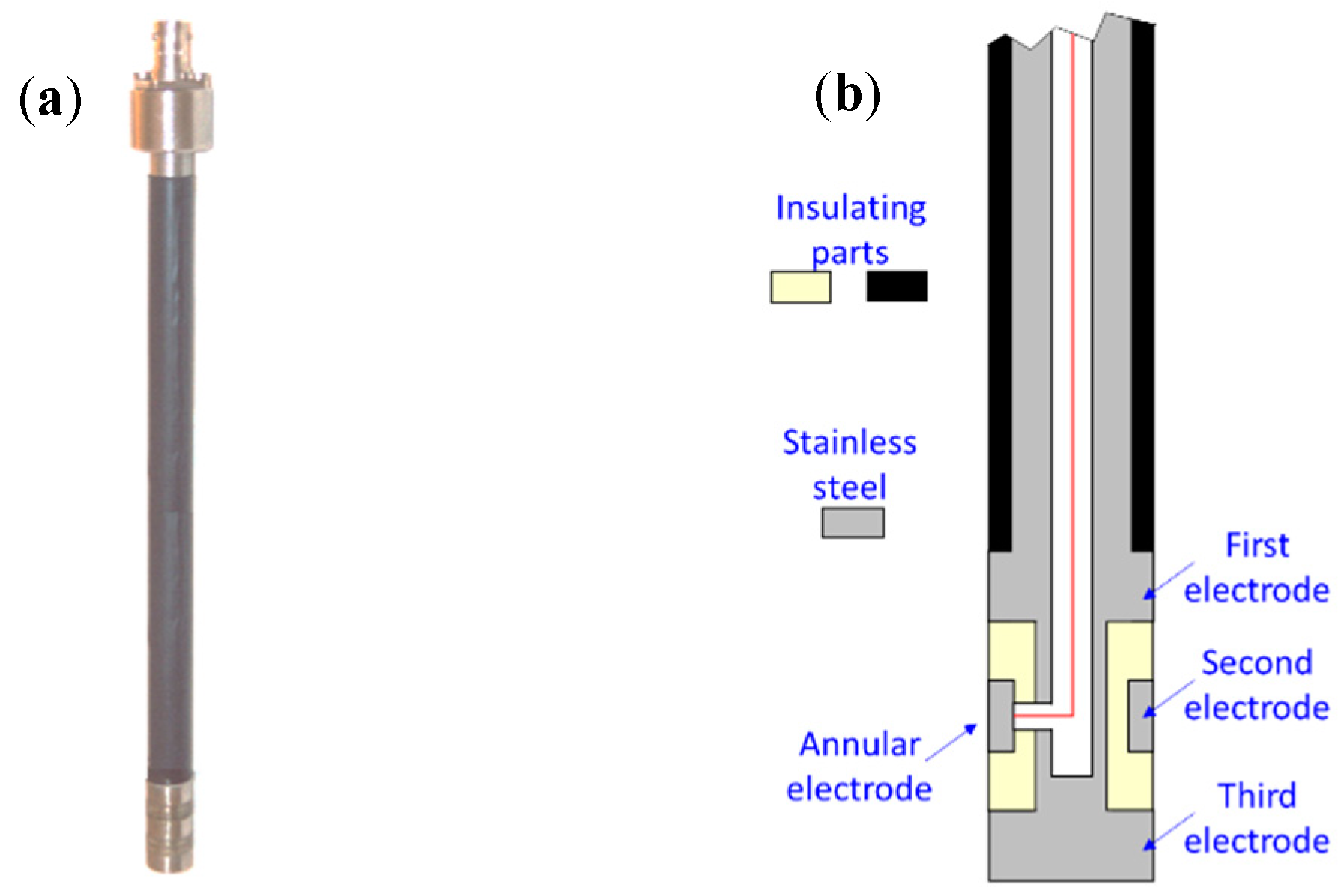
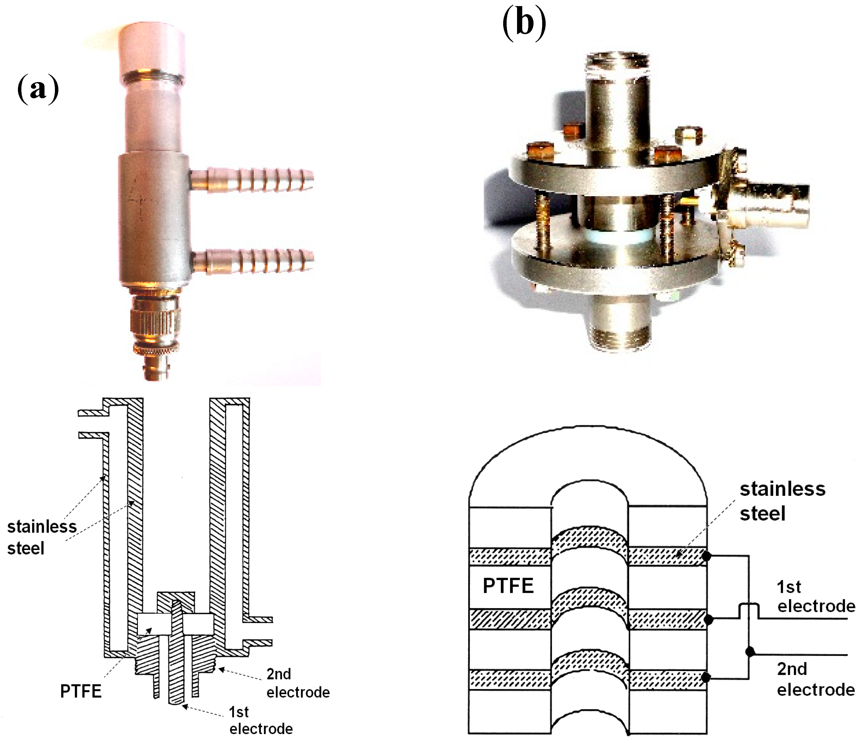
The geometric profile of the SDP (Figure 1) was inspired from that of the flow dielectric cell (FDC) in Figure 2b. The SDP is a sort of negative form of the FDC that comprises three cylindrical electrodes, two of which are short-circuited with one another. It consists essentially of a tube in stainless steel (250 mm in length and 14 mm in diameter) in the bottom of which is screwed the third electrode after carefully positioning the ring that constitutes the second electrode. This electrode is fixed with an epoxy resin that also serves as insulation material. The upper body of the cell is insulated with cross-linked polyolefin. In this study the response of the SDP is compared to those of a classic thermostatable dielectric cell (TDC) and of the FDC represented in Figure 2a,b respectively.

Figure 1.
Submersible dielectric probe (SDP): (a) Photograph, (b) Schematic representation.
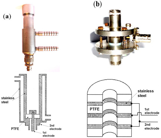
Figure 2.
Classic dielectric cells used for comparison purposes: (a) Thermostatable dielectric cell (TDC): photograph and schematic representation; (b) Flow dielectric cell (FDC): photograph and schematic representation.
3. Results and Discussion
In this work only the raw values of magnitude (Z) and phase (θ) provided by the vector impedancemeters were used without any mathematical treatment.
3.1. Comparison of the Response of the Submersible Probe with That of a Classic Dielectric Cell
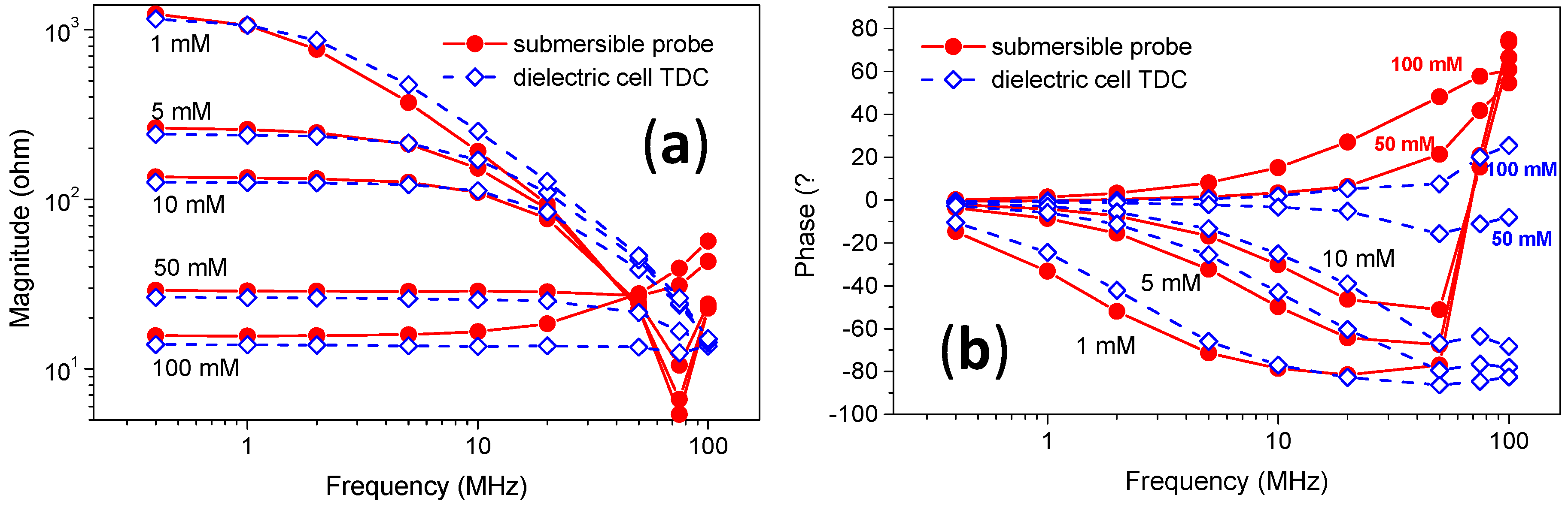
Figure 3 displays the responses of the submersible probe and the dielectric cell TDC for increasing concentrations of NaCl going from 1 to 100 mM in the 0.4–100 MHz frequency range. The comparison of the evolution of Z as a function of the frequency shows that the responses of both cells are close to each other, especially for frequencies lower than 10 MHz (Figure 3a). In contrast, the values measured with the flow cell are almost ten times higher despite the fact that the thicknesses of the cylindrical electrodes of cells SDP and FDC are the same (results not shown here). At high frequencies, the influence of the relatively long wiring inside the submersible probe body is responsible for the discrepancies noted above. Regarding the phase, Figure 3b shows that the measurements can be equally used in the 1–100 MHz frequency range. Moreover, the data spread more with the SDP in the case of the more concentrated solutions that increases the sensitivity of this probe. In fact, the geometric profile of SDP was optimized in this way. As will be seen below, if the measurement of Z is easy whatever the impedancemeter, this is not the case for θ where it is necessary sometimes to detect changes of a few hundredths of degree.
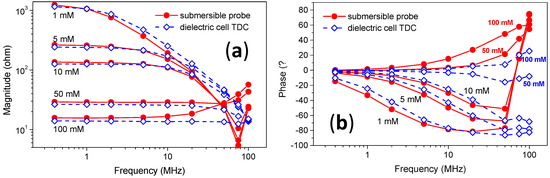
Figure 3.
Comparison of the dielectric response of the submersible probe with that of a classic thermostatable dielectric cell for increasing concentrations of NaCl in the 1 to 100 mM range: (a) Magnitude; (b) Phase.
3.2. Real-Time Monitoring of Activated Sludge in Pilot Reactors
The submersible probe was employed to monitor in real-time the activated sludge in pilot reactors continuously fed with sludge from a main reactor of the waste water treatment plant; the SDB was immersed in the reactor and the FDC was traversed by the sludge supply. It was therefore possible, without using a branch circuit, to visualize usual changes of the dielectric parameters related to transitions from day to night and from week to weekend (Figure 4a) as well as those caused by a severe thunderstorm or the road salting in wintertime (Figure 4b).
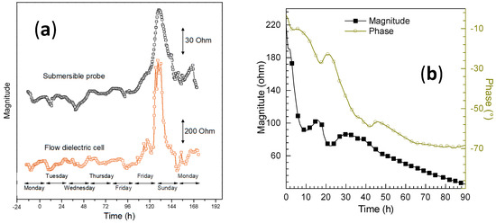
Figure 4.
Real-time monitoring of the activated sludge in a pilot reactor (measurements made at 0.4 MHz): (a) usual changes of the dielectric parameters for a week by means of the submersible probe (SDP) and a flow dielectric cell (FDC); (b) after the road salting in wintertime with the SDP.
3.3. Monitoring of Deliberate Dysfunctions
These operations were performed in independent pilot reactors. We can quote for example the addition of hypochlorite, copper or large quantities of NaCl and some measurements made under hypoxic or anoxic conditions. Figure 5 shows that the decrease of the O2 concentration from 7 to 3 mg/L provokes a sudden drop of θ of about one degree.
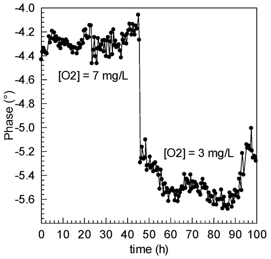
Figure 5.
Monitoring of the activated sludge in a pilot reactor during a deliberate hypoxic stress. Influence of the decrease in oxygen on the phase (measurements made at 0.4 MHz).
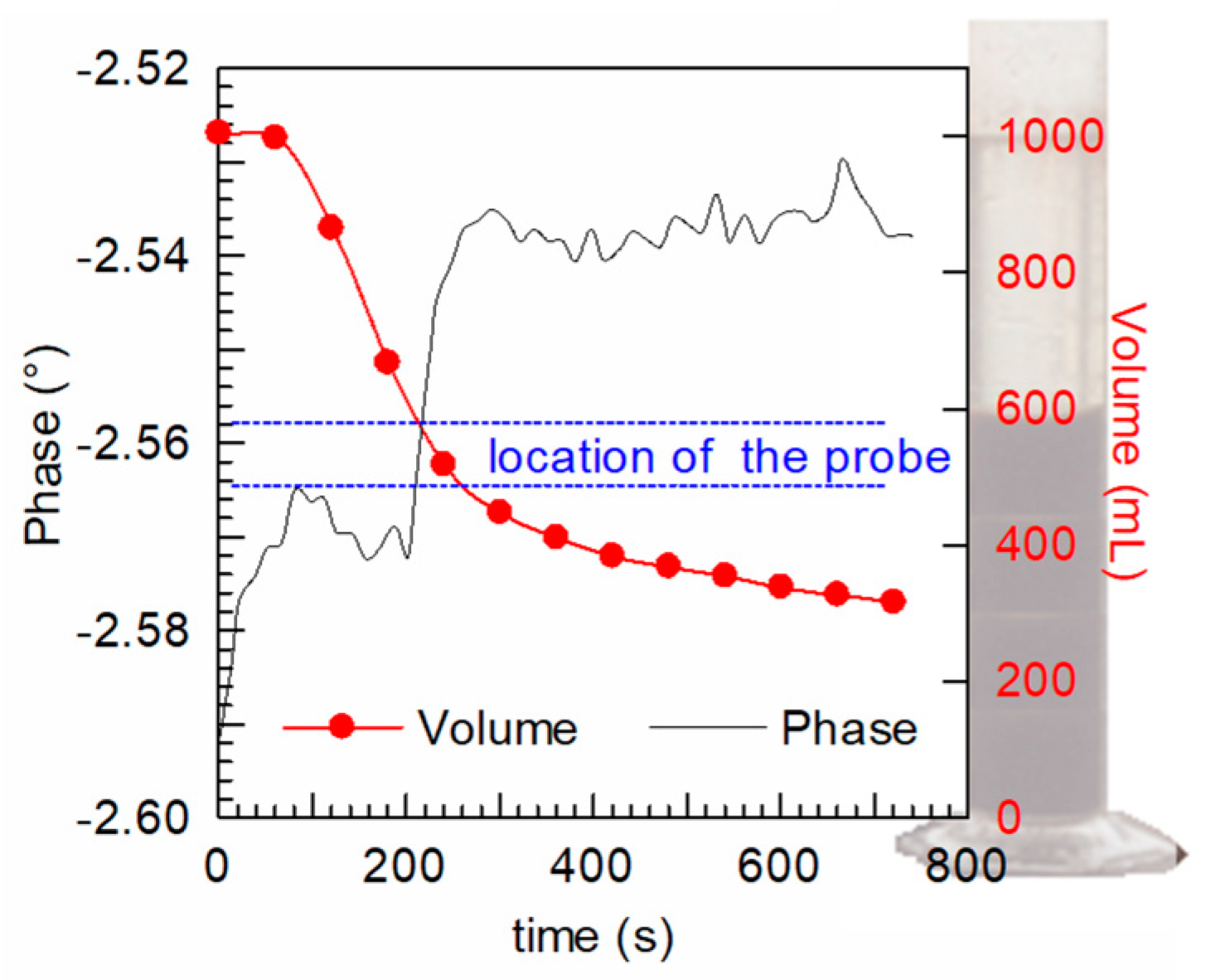
3.4. Monitoring of the Settling of the Sludge
Figure 6 shows the comparison between the visual progress of the front of sludge and the changes of the phase during the settling of an activated sludge. The evolution of this physical quantity is well-suited to monitor the phenomenon of settling because the values of θ do not depend significantly on temperature. This is not the case for Z and the control of the process by Z requires thermal regulation.
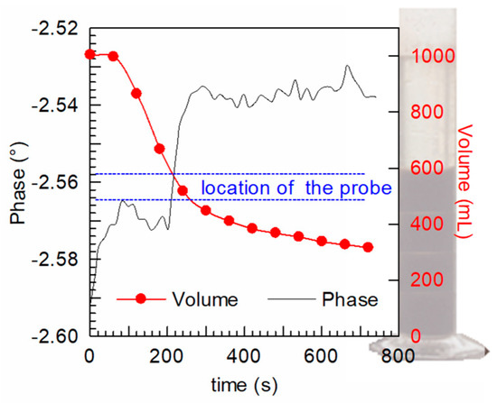
Figure 6.
Monitoring of the activated sludge settling with the submersible dielectric probe. Comparison with the visual progress of the front of sludge (measurements made at 0.4 MHz).
4. Conclusions
We have just seen that the developed submersible dielectric probe is a useful tool that is effective to substitute classic dielectric cells in industrial applications. The use of the submersible dielectric probe leads to results as good as, if not better than those obtained using a static or a flow dielectric cell. Moreover, its use does not require sampling or a branch circuit. However, we still have to deepen our knowledge on the influence of the dimensions and nature of the container on the dielectric measurements.
Acknowledgments
This work was carried out as part of a research program coordinated by the International Water Center (NanCIE, Nancy, France) and supported by Lyonnaise des Eaux.
Conflicts of Interest
The authors declare no conflict of interest.
References
- Benoit, E.; Guellil, A.; Block, J.C.; Bessière, J. Dielectric permittivity measurement of hydrophilic and hydrophobic bacterial suspensions: a comparison with the octane adhesion test. J. Microbiol. Methods 1998, 32, 205–211. [Google Scholar] [CrossRef]
- Pajoum-Shariati, F.; Sarrafzadeh, M.H.; Mehrnia, M.R.; Sarzana, G.; Ghommidh, C.; Grasmick, A.; Heran, M. Dielectric monitoring and respirometric activity of a high cell density activated sludge. Environ. Technol. 2014, 35, 425–431. [Google Scholar] [CrossRef] [PubMed]


Publisher’s Note: MDPI stays neutral with regard to jurisdictional claims in published maps and institutional affiliations. |
© 2017 by the authors. Licensee MDPI, Basel, Switzerland. This article is an open access article distributed under the terms and conditions of the Creative Commons Attribution (CC BY) license (https://creativecommons.org/licenses/by/4.0/).