Abstract
We present a fully coupled multi-energy domain compact model of a MEMS microphone dedicated to the investigation of acoustic high-frequency effects affecting the device behavior. To this end, the components of the acoustic domain are described using physics-derived analytical expressions. Finite element simulations are employed to confirm the validity of the acoustic submodel. The differential equations governing the small-signal dynamics of the electrically actuated transducer are solved in the frequency domain with MATLAB. The full-system model is calibrated and validated with experimental data. Measurements and simulations show very good agreement, which highlights the reliability of the presented modeling approach.
1. Introduction
The functionality of MEMS sensors and actuators is strongly influenced by the interaction between the device and the environment. In the case of MEMS microphones, the coupling between the electro-mechanical and the acoustic domain plays a key role in the device operation. On the one hand, fluidic damping mechanisms occurring inside the device are one of the major obstacles towards high signal-to-noise ratios (SNRs) [1]. On the other hand, acoustic effects introduced by the package influence, and possibly deteriorate, the performance of such devices [2]. In fact, when air is oscillating in a constrained volume, so called high-frequency acoustic effects arise depending on the oscillation frequency [3]. The impact of the latter effects can be conveniently characterized by studying the dynamics of the electrically actuated movable membrane of the microphone. This characterization approach also allows the investigation of the device behavior for frequencies above the audible range. In this work we present a physics-based fully coupled electro-mechanical-acoustic transducer model which captures the small-signal frequency response of the displacement of the membrane. The obtained system description allows the physical interpretation of the measured dynamics of the device.
2. Methods
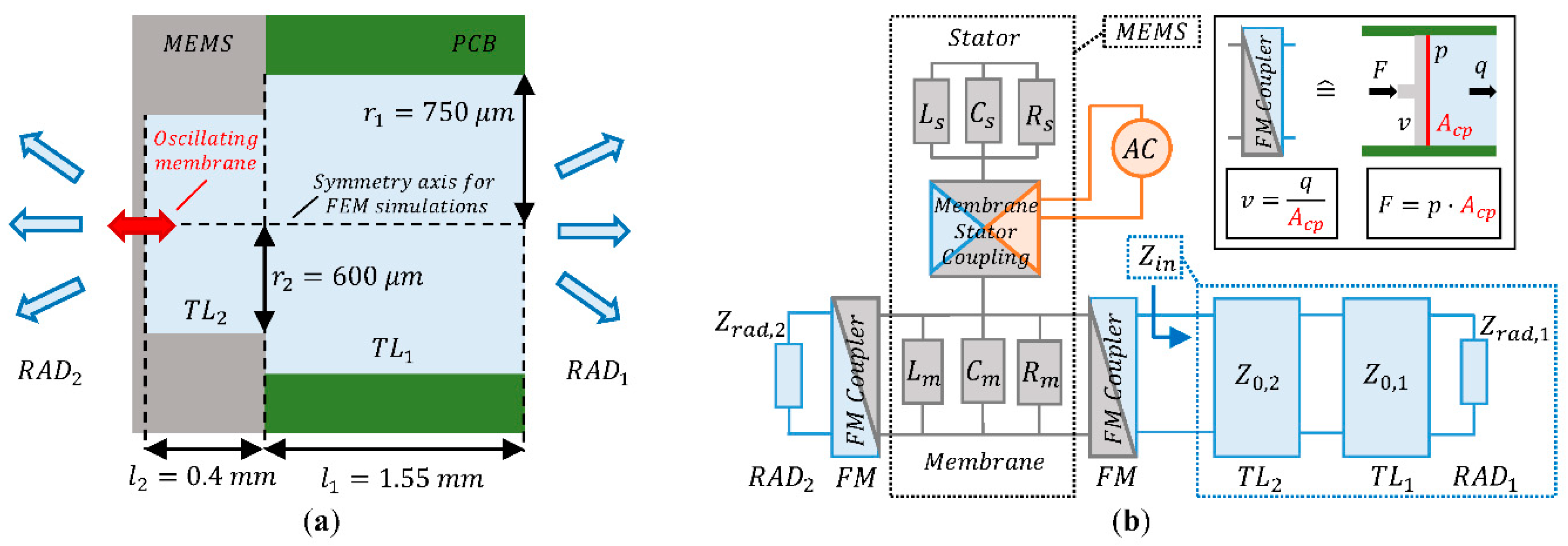
We consider the novel MEMS microphone presented in [4] which is attached to a printed circuit board (PCB) for convenient characterization of the system behavior (see Figure 1a). Due to the peculiar design of the microphone, which is based on an interdigitated finger capacitive readout between a movable membrane and a counter electrode called stator, we assume that only the sensing membrane is strongly interacting with the surrounding air. The cavity of the device and the hole in the PCB form a circular acoustic channel, which can be modeled by two acoustic transmission lines 𝑇𝐿1 and 𝑇𝐿2. When oscillating, the membrane generates sound waves on the PCB side (RAD1) and on the MEMS side (RAD2). This modeling approach captures both, the effects related to the propagation of sound waves and the impact of acoustic high-frequency effects. The presented system topology can be elegantly translated into the multi-energy domain equivalent circuit shown in Figure 1b by applying the modeling framework of generalized Kirchoffian networks [5].
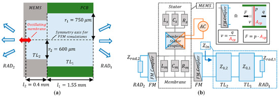
Figure 1.
(a) Schematic view of the system with geometrical dimensions; (b) Equivalent circuit composed of the acoustic (blue), the mechanical (grey) and the electrical (orange) energy domain.
In Figure 1b, the acoustic, the mechanical and the electrical energy domain are highlighted in blue, grey, and orange, respectively. The fluid-mechanical coupling element (FM Coupler) converts the mechanical force 𝐹 and the velocity 𝑣 into acoustic pressure 𝑝 and volumetric flux 𝑞 and vice versa. We assume that the membrane interacts with the air in a piston like motion through the coupling surface Acp. Due to this assumption, Acp does not correspond to the real membrane area and is used as a model calibration parameter. The acoustic input impedance Zin summarizes the acoustic components 𝑇𝐿2, 𝑇𝐿1 and 𝑅𝐴𝐷1, hence the acoustic channel and the sound radiation at its open termination. The MEMS submodel, which is used as starting point for this work, describes the interaction between membrane and stator at low pressure, hence without considering strong coupling with the surrounding air. The fluid-electro-mechanical coupling between the electrodes of the transducer has already been derived and validated in [6].
2.1. Modeling and Validation of the Input Impedance of the Acoustic Channel
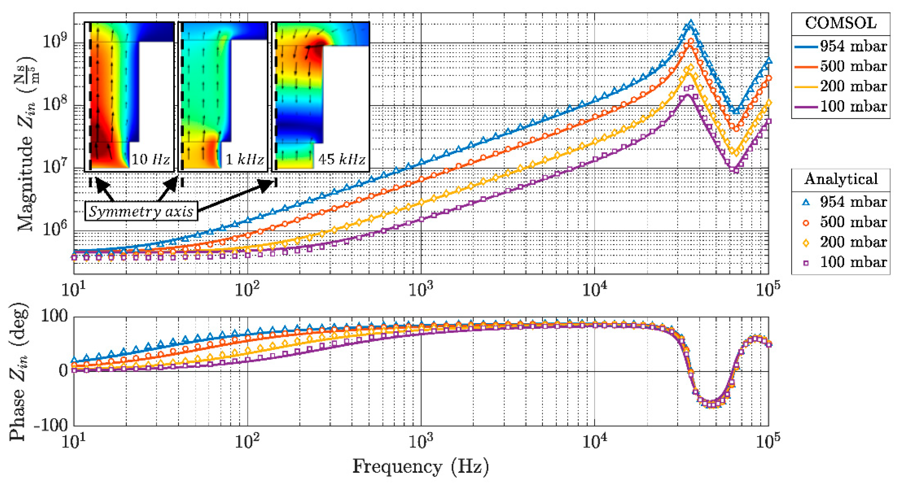
Inside the channel, different air velocity profiles are generated when the oscillation frequency increases. This physical effect is depicted in the insets of Figure 2 for three exemplary frequencies.
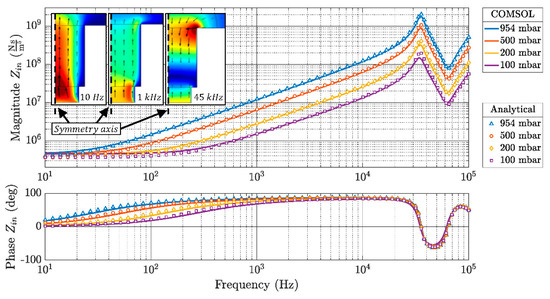
Figure 2.
Comparison between the analytically computed acoustic input impedance 𝑍𝑖𝑛 for different air pressure values and the results obtained by finite element simulations in COMSOL. The insets show exemplary velocity profiles inside the channel for different actuation frequencies.
The radial variation of the velocity distribution with increasing frequencies is comparable to the skin effect in an electrical conductor and can be considered the most prominent high-frequency acoustic effect. One of the key aspects of this work consists in the use of analytical formulas, whose complete derivation can be found in [3], to describe the frequency-dependent primary line constant of the acoustic TLs. The acoustic behavior of the sound waves propagating into free space is modeled using the radiation impedance Zrad given in [7]. The derivation of the acoustic TLs is based on the same theoretical framework as ordinary electrical TLs. Thanks to this analogy, conventional formulas can be employed to compute the characteristic impedance Z0 and all further parameters needed to analyze the interconnection of acoustic TLs. This approach allows the calculation of the input impedance Zin which fully describes the frequency-dependent acoustic behavior of the channel. Finite element simulations performed with COMSOL show the excellent validity of the analytical description for the geometry under investigation (see Figure 2). The acoustic model also includes the pressure dependence correctly.
2.2. Physical Interpretation of the Full System Model
The schematic given in Figure 1b fully describes the MEMS transducer and its interaction with the environment. However, the direct implementation of the equivalent circuit in a circuit simulator poses some difficulties due to the presence of frequency-dependent components. One could use transfer functions to describe the acoustic submodel, but that would require a fitting procedure. Here we perform the simulation of the full-system by adding the acoustic components to the transducer model presented in [6], where the small-signal dynamics of membrane and stator at low pressure is described by two coupled ordinary differential equations (ODEs). We start by reinterpreting the acoustic input impedance as follows:
where 𝑅𝑓 is an acoustic resistance, m𝑓 is an acoustic mass and 𝑁𝑓 an acoustic compliance. Please note that these parameters are frequency-dependent. Based on the phase of the acoustic input impedance it is possible to piecewise summarize 𝑍𝑖𝑛 as a purely resistive-inductive or as a purely resistive-capacitive impedance. The radiation impedance on the membrane side Zrad,2 is purely resistive-inductive. The fluid-mechanical coupling element shown in the inset of Figure 1b acts as a gyrator, transforming an acoustic impedance Zacoustic into a mechanical admittance Ymechanical:
The resulting mechanical admittances are connected in parallel with the RLC circuit used to model the oscillating membrane. In this way, the influence of the acoustic domain on the membrane dynamics can be interpreted as a frequency-dependent effective change of the membrane mass, spring stiffness and damping coefficient. The presented physical interpretation is used to properly determine the coefficients of the ODEs, which are implemented and solved in MATLAB.
3. Results and Discussion
The predictive power of the model is tested by comparing measurements obtained using a laser Doppler vibrometer and simulations performed at different values of the ambient air pressure. First, the model is calibrated by using the measurement at atmospheric pressure. This step is aimed at finding the value of Acp for the FM. Further simulations are run by changing the parameter under investigation e.g., the air pressure, while preserving all other model parameters. The electrical actuation is composed of an oscillating voltage with an amplitude of 0.1 V and a bias of 4 V.
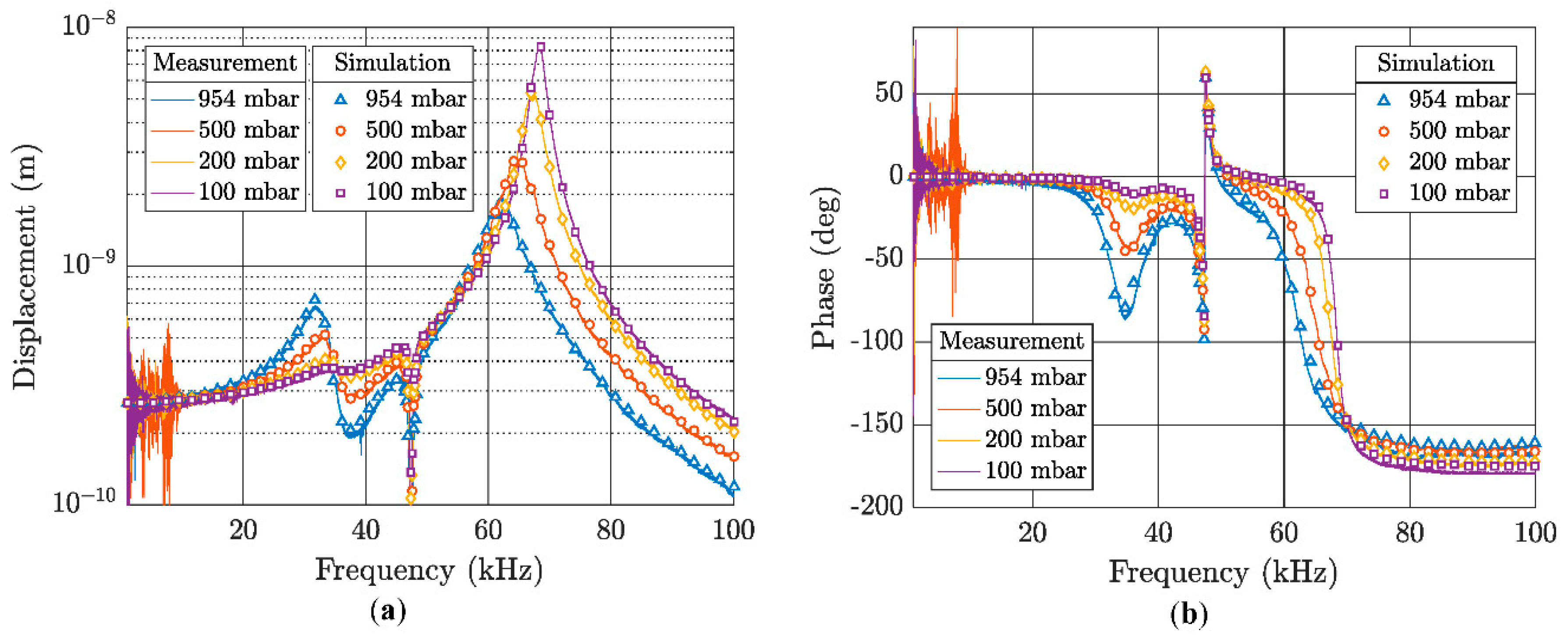
The frequency response of the displacement of the membrane given in Figure 3 exhibits two peculiar phenomena: first, various resonance peaks occurring between 20 kHz and 45 kHz; second, the shift of the membrane resonance frequency between 60 kHz and 70 kHz. Both effects are related to the frequency-dependent acoustic effects since they show a clear air pressure dependence. The antiresonance dip at 47.5 kHz arises due to the interaction between the membrane and the stator, as explained in [6].
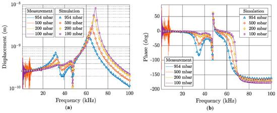
Figure 3.
Comparison of the measured and the simulated frequency response of the displacement of the membrane for different ambient pressure values. These results refer to the full-system simulation of the electrically actuated transducer. (a) Magnitude of the displacement of the membrane; (b) Phase shift between the oscillating input voltage and the displacement of the membrane.
4. Conclusions
We presented a full-system model, which allows easy, fast and detailed simulation of electro-mechanical-acoustic MEMS transducers. The model includes the impact of both, sound waves propagation and high-frequency acoustic effects on the device behavior. The simulations correctly reproduce the measured frequency responses of the displacement of the transducer membrane as well as the pressure dependence of its dynamics. These promising results set a solid base for the investigation of further channel geometries and of other relevant working scenarios, e.g., sealed acoustic channel, for the here presented transducer and also for similar device concepts.
Acknowledgments
This project has received funding from the Electronic Component Systems for European Leadership Joint Undertaking (Grant Agreement No. 692480).
Conflicts of Interest
The authors declare no conflict of interest. The founding sponsors had no role in the design of the study; in the collection, analyses, or interpretation of data; in the writing of the manuscript, and in the decision to publish the results.
References
- Kuenzig, T.; Schrag, G.; Dehé, A.; Wachutka, G. Performance and noise analysis of capacitive silicon microphones using tailored system-level simulation. In Proceedings of the Transducers 2015 18th International Solid-State Sensors, Anchorage, Alaska, USA, 21–25 June 2015. [Google Scholar]
- Schrag, G.; Kuenzig, T.; Pham, D.; Glacer, C.; Dehé, A.; Wachutka, G. Acoustic high-frequency effects inside the package of capacitive silicon microphones and their impact on the device performance. Proc. SPIE 2015, 9517, 95170M. [Google Scholar] [CrossRef]
- Schaedel, H. Theoretische Untersuchungen an homogenen Übertragungsleitungen der Fluidik. Frequenz 1969, 23, 350–358. [Google Scholar] [CrossRef]
- Manz, J.; Bosetti, G.; Dehé, A.; Schrag, G. A novel silicon “Star-Comb” microphone concept for enhanced signal-to-noise-ratio: Modeling, design and first prototype. In Proceedings of the 2017 19th International Conference on Solid-State Sensors, Actuators and Microsystems, Kaohsiung, Taiwan, 18–22 June 2017. [Google Scholar]
- Schrag, G.; Wachutka, G. System-Level Modeling of MEMS using Generalized Kirchoffian Networks- Basic Principles. In System-Level Modeling of MEMS; Wiley-VCH Verlag GmbH & Co.: Weinheim, Germany, 2012; pp. 19–51. [Google Scholar]
- Bosetti, G.; Manz, J.; Krumbein, U.; Schrag, G. Modeling and physical analysis of an out-of-plane capacitive MEMS transducer with dynamically coupled electrodes. Microsyst. Technol. under review. [CrossRef]
- Morse, P. Theoretical Acoustics; Princeton University Press: Princeton, NJ, USA, 1968. [Google Scholar]
Publisher’s Note: MDPI stays neutral with regard to jurisdictional claims in published maps and institutional affiliations. |
© 2018 by the authors. Licensee MDPI, Basel, Switzerland. This article is an open access article distributed under the terms and conditions of the Creative Commons Attribution (CC BY) license (https://creativecommons.org/licenses/by/4.0/).