Abstract
This work presents a design approach that improves power management circuit (PMC) for energy harvesting applications so that more of the harvested energy can be utilized by the wireless sensor nodes (WSNs) to perform useful tasks. The proposed method is widely applicable to different circuits by setting an appropriate threshold voltage at the energy flow control interface of the circuit. Experimental results show that with a threshold voltage difference of around 20 mV, the energy output from the PMC can differ by more than 5%. This difference is significant over a long period of time as more tasks can be performed by the WSN with the extra energy.
1. Introduction
With the rise in popularity of the Internet of Things (IoT), wireless sensor nodes (WSNs) which are one of the enabling technologies have received increasing attention. This is because WSNs are easier and cheaper to be deployed at a large area than wired systems. WSNs are usually powered by batteries where regular battery replacement, which can be labor intensive and costly is required to ensure that the WSNs can continue to operate [1]. Therefore, there has been a growing interest in applying energy harvesting that converts energy sources such as vibration, thermal, solar and wind from the ambient environments into electrical energy to power WSNs to overcome the issue of limited energy from batteries for long term and uninterrupted operation of WSNs.
Energy sources from the surroundings can be sporadic and of variable nature, and so the electrical output from energy harvesters [2]. Therefore, a power management circuit (PMC) is required to manage the energy from the energy harvesters and provide electrical energy in a usable form to the WSNs. The harvested energy is usually stored in an energy storage device such as a capacitor and is released to the WSNs once the capacitor voltage reaches a specific threshold voltage, as controlled by an energy flow control interface (EFCI) [3,4]. Although tremendous progress has been achieved in improving the performances of the PMCs by including features such as maximum power point tracking [5], power extraction [6], very low start-up voltage and low power consumption [7], no investigation has been done on the energy flow control interface to improve the energy utilization efficiency. This work presents a method that improves amount of energy that is usable by the WSNs through threshold voltage control at the EFCI.
2. Threshold Voltage Control
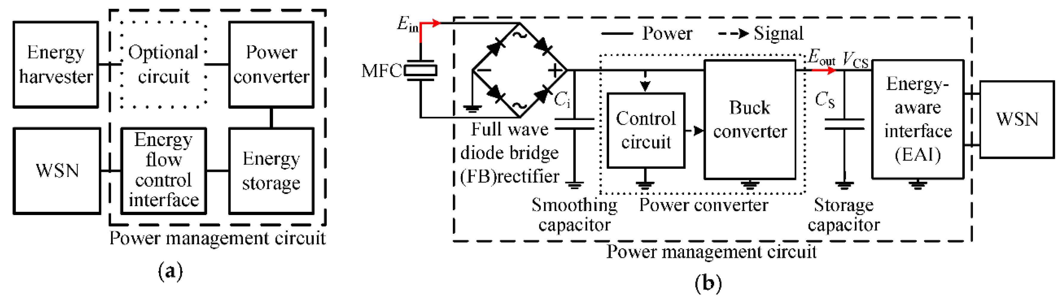
Common architecture of a PMC includes a power converter, an energy storage device and an interface to control energy flow from the energy storage device to the WSN as shown in Figure 1a. The EFCIs can be low-dropout (LDO) regulators [8], DC–DC converters [9] or any custom-designed circuitries [3,7,10] with two threshold voltages to turn-on and turn-off the WSNs, respectively. The threshold voltages are usually set based on the operating voltage range of the WSNs [3,4,7]. The power converters are usually set to maintain their output voltage at a fixed value and are used to charge up the energy storage capacitor towards the preset value [2,4,7]. It should be noted that power converters usually have low efficiency when their output power is low [11,12]. If the EFCIs have a turn-on threshold voltage VTH,on that is equal to the preset output voltage of the power converters, there will be a short period of time where the power converters are operating at lower efficiency. This is because the output voltage from the power converters is limited to not exceed their preset voltage. The EFCIs might have a slight delay in turning on the WSNs when the capacitor voltage has reached the VTH,on, which also limits the output power from the power converters. Hence, the VTH,on of an EFCI has to be lower than the maximum output voltage of the power converter.
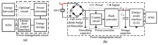
Figure 1.
Block diagram of: (a) Common architecture of PMC where the optional circuit can be a rectifier; (b) Circuit used in the experiment where the EFCI is an energy-aware interface (EAI) [4].
3. Experimental Characterization
A circuit as shown in Figure 1b was used to determine the influence of VTH,on of the EFCI on the efficiency of the PMC. The power converter of the PMC was set to output a maximum of 3.3 V. Two different turn-on threshold voltages of 3.28 and 3.3 V at the EFCI were used. The input energy Ein and output energy Eout of the PMC in both cases were compared. To verify that the proposed control is applicable to different circuits, the experiment was repeated by using a LDO as the EFCI.
3.1. Experimental Setup
A macro fiber composite (MFC) was used as the energy harvester [4]. A cyclic peak-to-peak strain loading of 500 µε with the frequency of 10 Hz was applied onto the MFC by using an Instron testing machine. For simplicity, a 500 Ω resistor was used to represent a WSN. The energy storage device is a 22 mF supercapacitor. For a fair comparison, once the capacitor is charged up to the respective threshold voltages of 3.28 V and 3.3 V, it will be discharged by the resistor for 5 s in both cases. 5 s was chosen to emulate a time that is practically long enough for a WSN to complete its tasks such as initialization, sensing, data processing and wireless communication.
3.2. Results and Discussions
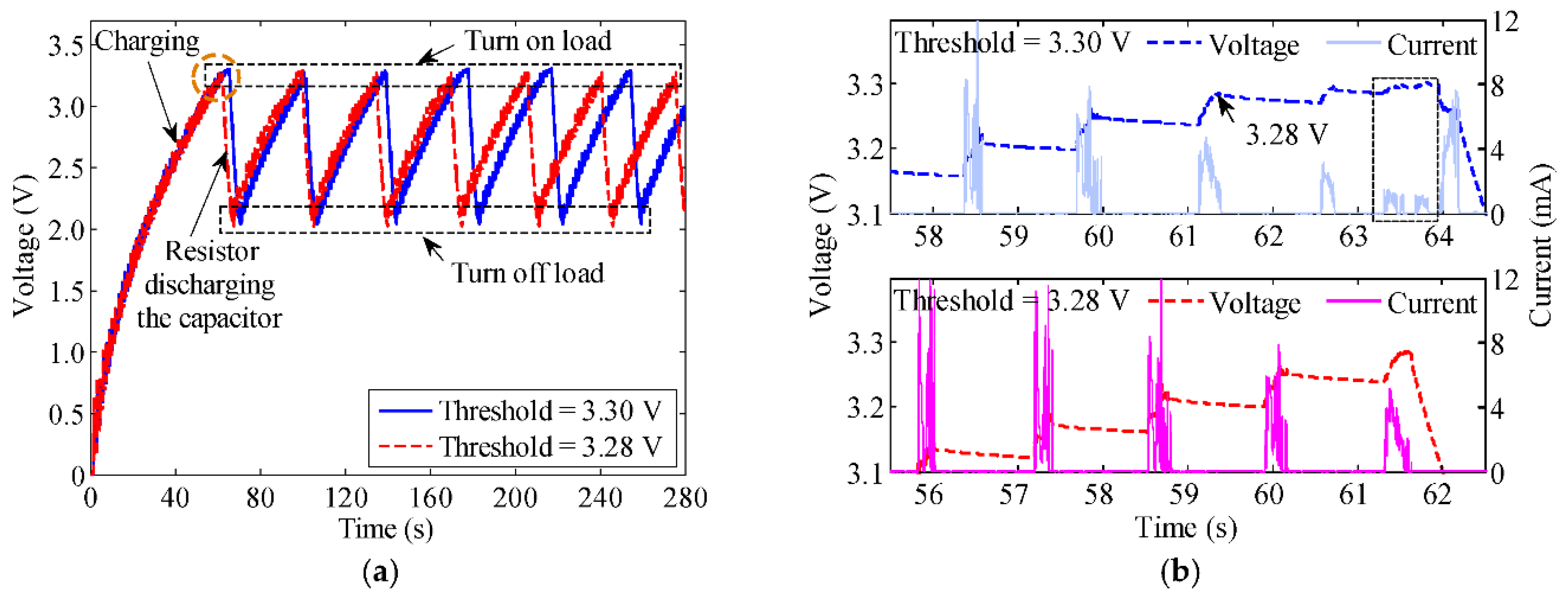
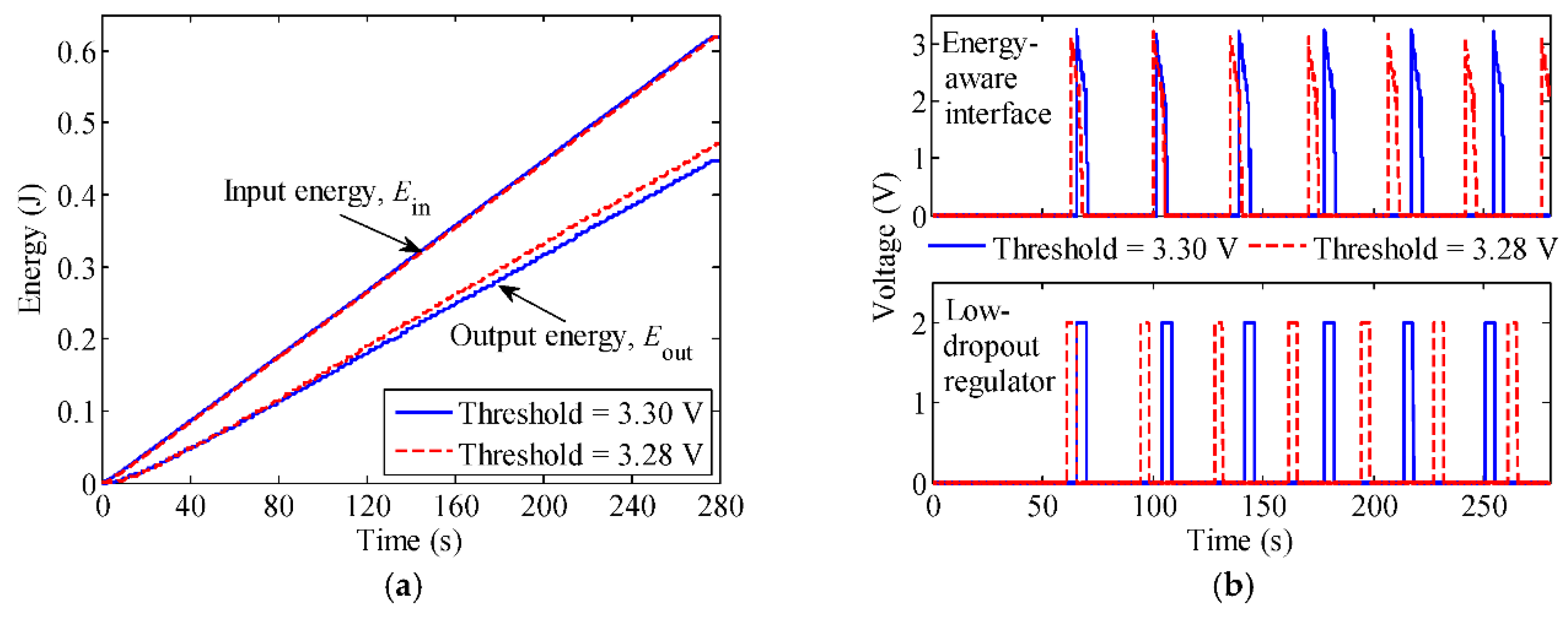
Figure 2a shows the PMC charges up the capacitor faster and turns on the load more often when the VTH,on is 3.28 V. To verify that the more frequent turn-on times of the load is due to a higher energy transfer, a closed up view of the area highlighted by the circle in Figure 2a with current measurements is shown in Figure 2b. The power converter charges the capacitor with a lower current when the capacitor voltage is almost 3.3 V, when VTH,on was set to 3.3 V, which is equal to the maximum output voltage of the power converter. It takes more than 1 s to charge the capacitor from 3.28 V to 3.3 V. There is no such issue when the VTH,on is 3.28 V, away from the maximum output voltage of the power converter. Therefore, the total energy transfer from the PMC with a VTH,on at 3.28 V is more than the one at 3.3 V in a given time frame, as confirmed by the results in Figure 3a. The input energy to the PMC is comparable with different threshold voltages. However, the output energy from the PMC with a VTH,on at 3.28 V is 5.28% more than the one at 3.3 V.
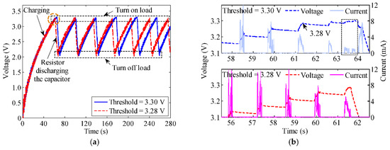
Figure 2.
(a) Voltage profile VCS of the storage capacitor shows that the capacitor can be charged up faster and more frequently for the load to be powered up more often when the turn-on threshold is 3.28 V; (b) Enlarged view of the area highlighted in the circle from Figure 2a. The area within the dashed rectangle shows that the capacitor is charged up by the buck converter with lower current.
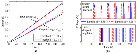
Figure 3.
(a) Input and output energies of the power management circuit with threshold voltages of the energy flow control interface set to 3.30 V (solid) and 3.28 V (dashed) respectively; (b) Electrical load can be turned on more frequently by applying the proposed design rule on different energy flow control interfaces of energy-aware interface (top) and low-dropout regulator (bottom).
Figure 3b shows the voltage measured across the resistive load that emulates a WSN using different energy flow control interfaces. The load was turned on and off at their respective threshold voltages, leading to the pulse-like voltage profiles. The proposed design rule is shown to be applicable to different interfaces where both circuits that have their VTH,on set at 3.28 V turn on the load more often in a given time frame. Based on the measurement in Figure 3b, the number of times that a WSN can be turned on in a day using different VTH,on of 3.3 V and 3.28 V is summarized in Table 1. The WSN can be turned on for an extra 211 and 256 times using the EAI and LDO at a VTH,on of 3.28 V, which is 9.3% and 10.9% more than the VTH,on at 3.3 V, respectively. The extra turn on times is beneficial if a WSN is to operate autonomously for a longer period of time uninterrupted.

Table 1.
Number of times a WSN can turn on in a day using different threshold voltages and EFCIs.
4. Conclusions
A control method to improve the energy utilization efficiency of a PMC has been demonstrated. The proposed control is simple to implement in any energy flow control interface. Energy transfer from the energy harvester to the energy storage can be improved by avoiding the turn-on threshold voltage of the energy flow control interface to be equal to the maximum output voltage of the power converter in a PMC. Experimental results showed that 5.28% more energy can be obtained by conforming to the proposed control method. Based on the prototyped circuits, WSNs can therefore be turned on more often by more than 9%. This means more tasks such as condition or structural health monitoring can be done by the WSN to give more assurances and bringing in more data which can be invaluable to the knowledge base for the benefit of the end users.
Acknowledgments
This work has been partly supported by the Engineering and Physical Sciences Research Council, U.K., through the project En-ComE under Grant EP/K020331/1 and Innovate UK through the project Multi-source power management to enable autonomous micro energy harvesting systems.
Conflicts of Interest
The authors declare no conflict of interest.
References
- Bogue, R. Wireless Sensors: A Review of Technologies, Products and Applications. Sens. Rev. 2010, 30, 285–289. [Google Scholar] [CrossRef]
- Magno, M.; Boyle, D.; Brunelli, D.; Flynn, B.O.; Popovici, E.; Benini, L. Extended Wireless Monitoring through Intelligent Hybrid Energy Supply. IEEE Trans. Ind. Electron. 2014, 61, 1871–1881. [Google Scholar] [CrossRef]
- Yu, H.; Zhou, J.; Deng, L.; Wen, Z. A Vibration-Based MEMS Piezoelectric Energy Harvester and Power Conditioning Circuit. Sensors 2014, 14, 3323–3341. [Google Scholar] [CrossRef] [PubMed]
- Chew, Z.J.; Ruan, T.; Zhu, M. Strain Energy Harvesting Powered Wireless Sensor System Using Adaptive and Energy-Aware Interface for Enhanced Performance. IEEE Trans. Ind. Inform. 2017, 13, 3006–3016. [Google Scholar] [CrossRef]
- Chew, Z.J.; Zhu, M. Adaptive Maximum Power Point Finding Using Direct VOC/2 Tracking Method with Microwatt Power Consumption for Energy Harvesting IEEE Trans. Power Electron. 2018, 33, 8164–8173. [Google Scholar] [CrossRef]
- Chew, Z.J.; Zhu, M. Combined Power Extraction with Adaptive Power Management Module for Increased Piezoelectric Energy Harvesting to Power Wireless Sensor Nodes. In Proceedings of the 2016 IEEE Sensors, Orlando, FL, USA, 30 October–3 November 2016; pp. 1–3. [Google Scholar]
- Katic, J.; Rodriguez, S.; Rusu, A. A Dual-Output Thermoelectric Energy Harvesting Interface with 86.6% Peak Efficiency at 30 μW and Total Control Power of 160 nW. IEEE J. Solid-State Circuits 2016, 51, 1928–1937. [Google Scholar] [CrossRef]
- Sanchez, D.A.; Leicht, J.; Hagedorn, F.; Jodka, E.; Fazel, E.; Manoli, Y. A Parallel-SSHI Rectifier for Piezoelectric Energy Harvesting of Periodic and Shock Excitations. IEEE J. Solid-State Circuits 2016, 51, 2867–2879. [Google Scholar] [CrossRef]
- Kong, N.; Ha, D.-S. Low-Power Design of a Self-Powered Piezoelectric Energy Harvesting System with Maximum Power Point Tracking. IEEE Trans. Power Electron. 2012, 27, 2298–2308. [Google Scholar] [CrossRef]
- Ruan, T.; Chew, Z.J.; Zhu, M. Energy-Aware Approaches for Energy Harvesting Powered Wireless Sensor Nodes. IEEE Sens. J. 2017, 17, 2165–2173. [Google Scholar] [CrossRef]
- Erickson, R.; Maksimovic, D. High Efficiency, Dc–Dc Converters for Battery Operated Systems with Energy Management; Department of Electrical and Computer Engineering, University of Colorado, Boulder, CO, USA, 1995, pp. 1–10. Available online: http://ecee.colorado.edu/~rwe/papers/EnergyMangmt.pdf (accessed on 2 May 2018).
- Carreon-Bautista, S.; Erbay, C.; Han, A.; Sanchez-Sinencio, E. An Inductorless DC–DC Converter for an Energy Aware Power Management Unit Aimed at Microbial Fuel Cell Arrays. IEEE J. Emerg. Sel. Top. Power Electron. 2015, 3, 1109–1121. [Google Scholar] [CrossRef]
Publisher’s Note: MDPI stays neutral with regard to jurisdictional claims in published maps and institutional affiliations. |
© 2018 by the authors. Licensee MDPI, Basel, Switzerland. This article is an open access article distributed under the terms and conditions of the Creative Commons Attribution (CC BY) license (https://creativecommons.org/licenses/by/4.0/).