Abstract
Electrical impedance spectroscopy is a widespread characterization method for solids or fluids in industrial applications. We here report on its thermal equivalent, the “thermal impedance spectroscopy”, improved by using a temperature compensation method for temperature dependent thermal measurements using an on-chip reference resistor.
1. Introduction
The electrical impedance spectroscopy uses a frequency dependent system response to a AC voltage signal and is determined by the electrical conductivity, capacity and inductivity of an analyte material. We measure in addition the frequency dependent thermal system response of a thermal excitation that depends basically on the thermal conductivity and heat capacity, using an adaption of the well-known 3-omega method [2].
2. Experimental
Here, an alternating current I0 of frequency ω is applied to a resistive heater with resistance RBol, causing temperature oscillations T and thus a modulation of the temperature dependent heater resistance with the double frequency 2ω. This results in a 3ω part V3ω of the measured heater voltage spectrum that can easily be separated and from that the amplitude of the temperature oscillation ΔT can be determined from:
where αR is the temperature coefficient of the heater material [2]. The amplitudes ΔT get higher with lower thermal conductivity of the analyte since the thermal heating power RBolI2 needs a higher temperature difference ΔT for dissipation into the analyte.
V3ω = 0.5 ΔT αR RBol I0
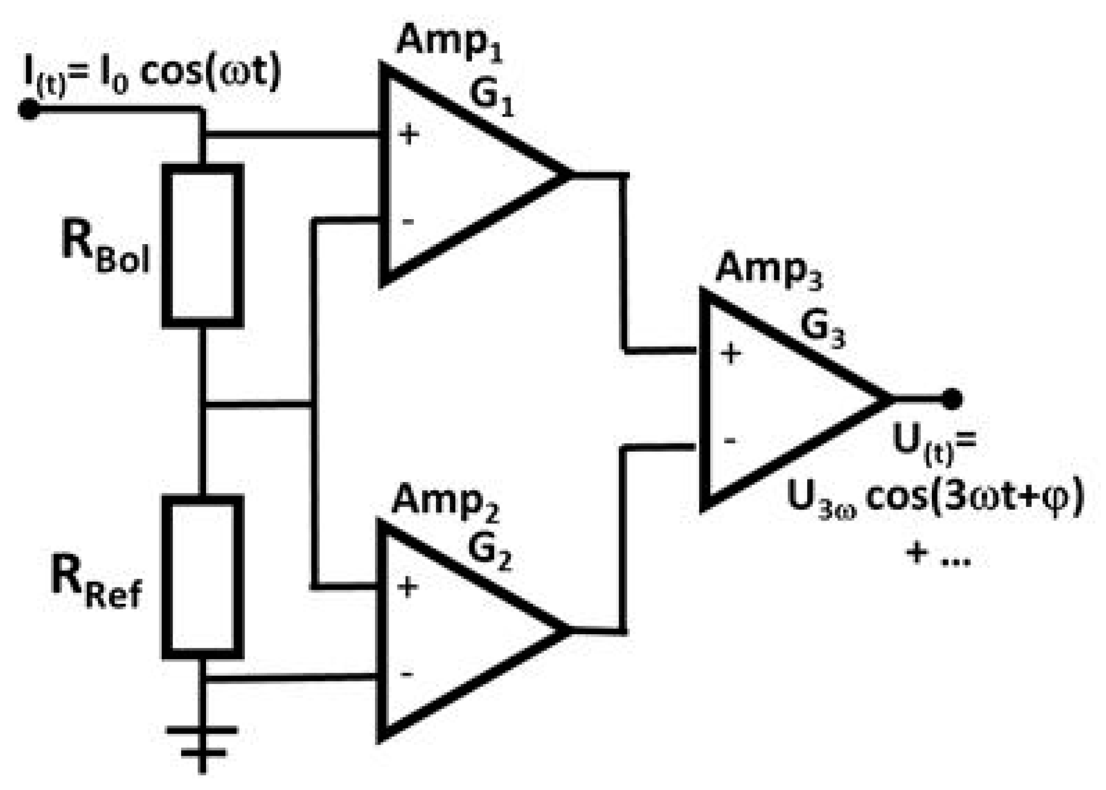
Typically, the 3ω voltage is a factor of thousand smaller than the heater voltage with frequency ω. In order to get a better signal to noise ratio SNR, there are methods to subtract the one omega heater voltage. Figure 1 shows a possible evaluation circuit. The same AC current I0 that drives the heater RBol flows through a reference resistor RRef connected in series. The bolometer voltage is amplified with gain G1. In addition, the voltage of the reference resistor is amplified with gain G2 and the two voltages are subtracted at amplifier 3.

Figure 1.
Example for an evaluation circuit for the 3ω voltage that is caused by the temperature modulation of a bolometer structure RBol that is driven by an AC current wit frequency ω. A reference resistor RRef is driven by the same AC current but without temperature modulation. The two resistor voltages are subtracted after an amplification with a matched gain ratio G1/G2 = RRef/RBol, obtaining an 3ω-signal with high signal to noise ratio.
Here it is important, that a temperature modulation only affects the heater but not the reference resistance. This can be done by using a reference resistor with negligible temperature dependence, for example constantan. Then, the gain factors can be adjusted to compensate widely the 1ω heater-voltage, leaving the 3ω voltage at a higher SNR or even enables a direct analogous measurement of the 3ω voltage. Often the reference resistor is integrated in the evaluation circuit board but this might be disadvantageous. For example, a change in the heater baseline temperature changes the resistance baseline due to the temperature dependency of the heater material and therefor the gain factors. That causes a signal drift unless the reference resistance is not adjusted at every temperature. To overcome this temperature drift, a reference resistor with the same temperature and temperature coefficient as the heater material is needed. We therefore used a reference resistor structure of the same material as the heater and placed it on the sensor chip. The temperature modulation in the reference RRef was avoided by using a much lower resistance value (for example with factor 20) so that the temperature modulation of the reference resistor is negligible.
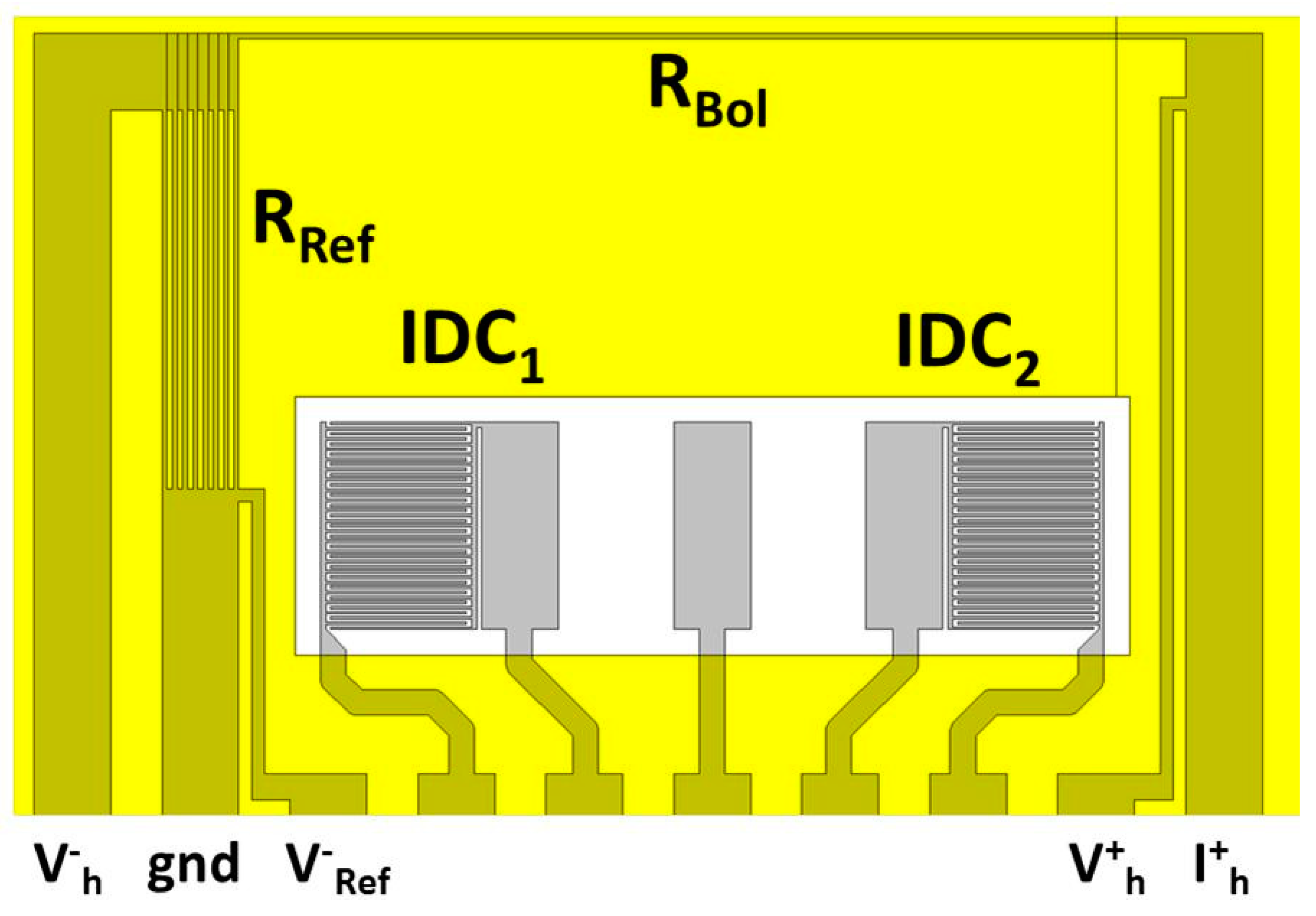
The results presented were obtained within a current development of a small electronic tongue system consisting of partially insulated gold electrodes on a polymer substrate (Figure 2). Besides interdigital capacitors (IDC) for the measurement of electric impedances, there are a linear heater structure RBol and a reference resistor RRef on the chip that both are driven by the same AC heater current I0. Here the heater structure RBol consists of a structured metal strip of gold (3700 µm long, 20 µm wide and 0.2 µm thick). The reference resistor RRef consists of 8 shorter metal strips (1470 µm long, 20 µm wide, 0.2 µm thick) connected in parallel, it is lower by a factor of about 20. If the gain ratio of G1/G2 = RRef/RBol, most of the 1ω part of the bolometer voltage is subtracted, the 3ω-part is passing amplifier 3 with a high signal to noise ratio. If the temperature of the analyte changes, both resistor structures change in resistance so the gain ratio inherently keeps constant and a temperature induced change of RBol is compensated automatically.

Figure 2.
Example for a chip layout with interdigital capacitors IDC for electric impedance spectroscopy and a heater structure RBol for measuring the thermal conductivity using the 3ω voltage caused by its heat modulation. The same AC current flows through RBol and a much lower reference resistor RRef so no heat modulation occurs here. Temperature changes of the chip affect both resistors and are thus compensated automatically.
3. Results
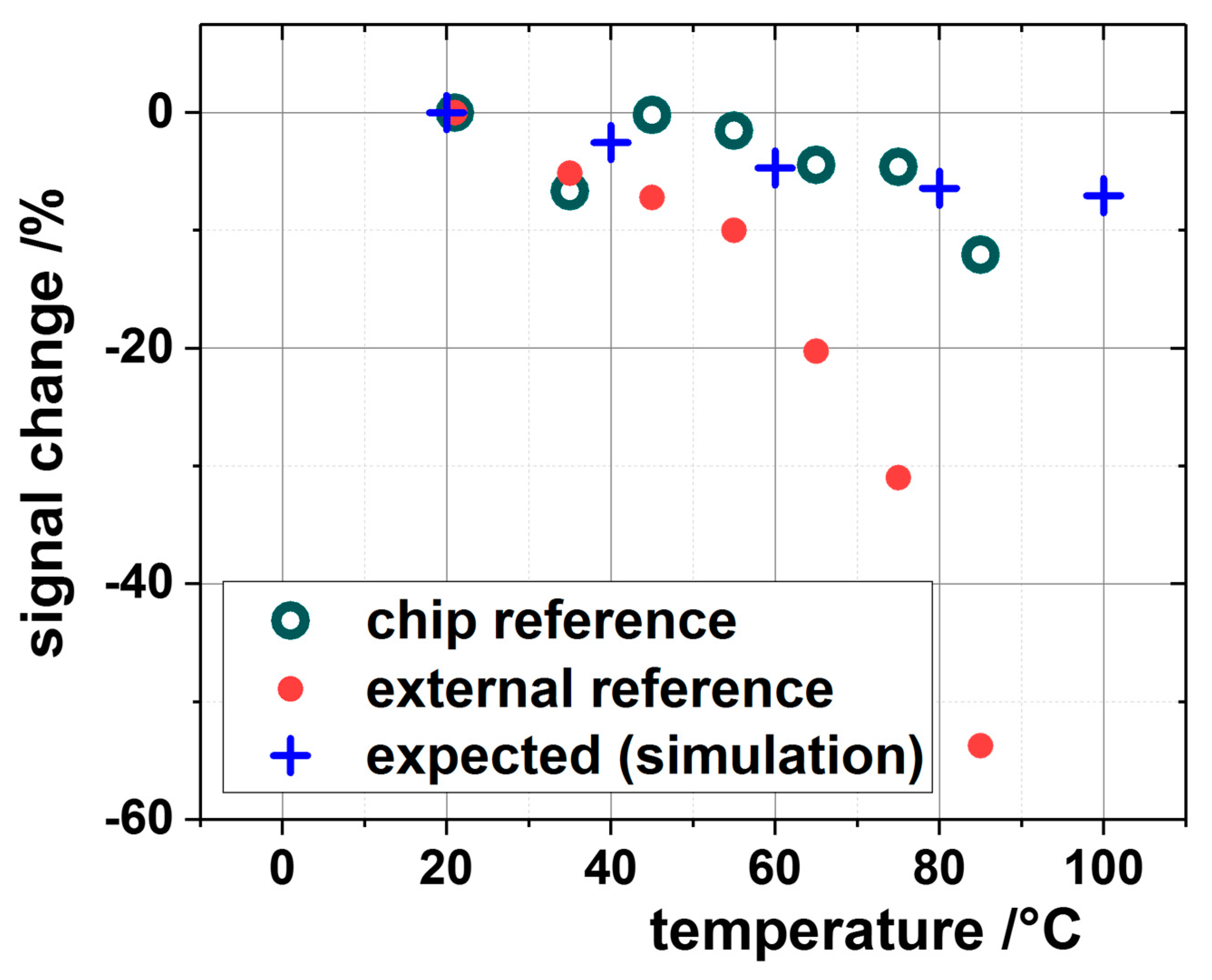
If the resistivity of the reference is low enough, its heating power and thus the temperature modulation is insignificant and no 3ω -signal occurs. As an example, in Figure 3, the signal changes in water of a compensated configuration as described above (green) and an uncompensated measurement using a constant external reference resistor fixed at 20 °C (red) is shown over temperature.

Figure 3.
3ω Measurement of water from 20 °C to 80 °C with on-chip reference (green circles) and fixed external reference at 20 °C (red points). The expected values are marked as blue crosses and describes the influence of the temperature dependency of the specific thermal properties of water to the 3ω-signal according to a COMSOL simulation. The uncompensated method shows strong deviations with higher temperatures (red points).
The expected signal change due to the temperature dependent change of the water properties is shown as blue crosses. Here the sensor signal was simulated with a COMSOL model of the sensor with the temperature dependent properties of water. The uncompensated method shows strong deviations at higher temperatures. The measurement of the thermal impedance is a reasonable extension to electrical impedance measurements. Currently, such thermal-electric impedance spectroscopy measurements are tested for process and quality control in fluids [1].
Author Contributions
M.J., H.-F.P. and M.P. designed the sensors and the experiments, M.B. (Mike Benkendorf) and M.B. (Markus Bartel) developed the sensor system, S.D. and X.L. were involved in the sensor technology development.
Acknowledgments
Parts of this work were funded by the Ministerium für Finanzen und Wirtschaft, Baden Württemberg, Germany (project Ölmonitor) and the Fraunhofer Gesellschaft, Munich, Germany.
Conflicts of Interest
The authors declare no conflict of interest. The founding sponsors had no role in the design of the study; in the collection, analyses, or interpretation of data; in the writing of the manuscript, and in the decision to publish the results.
References
- Jägle, M.; Pernau, H.-F.; Pfützner, M.; Benkendorf, M.; Li, X.; Bartel, M.; Herm, O.; Drost, S.; Rutsch, D.; Jacquot, A.; et al. Thermal-electrical impedance spectroscopy for fluid characterization. Procedia Eng. 2016, 168, 770–773. [Google Scholar] [CrossRef]
- Cahill, D.G. Thermal conductivity measurement from 30 K to 750 K: The 3-omega method. Rev. Sci. Instrum. 1990, 61, 802–808. [Google Scholar] [CrossRef]
Publisher’s Note: MDPI stays neutral with regard to jurisdictional claims in published maps and institutional affiliations. |
© 2018 by the authors. Licensee MDPI, Basel, Switzerland. This article is an open access article distributed under the terms and conditions of the Creative Commons Attribution (CC BY) license (https://creativecommons.org/licenses/by/4.0/).