Proceeding Paper

Detection of Heart and Respiration Rate with an Organic-Semiconductor-Based Optomechanical MEMS Sensor †

1
Institute of Sensor and Actuator Systems, TU Wien, 1040 Vienna, Austria
2
Department for Integrated Sensor Systems, Danube University Krems, 2700 Wiener Neustadt, Austria
3
Institute of Electro-Optical Engineering, National Chiao Tung University, Hsinchu 300, Taiwan
4
Institute of Physics, National Chiao Tung University, Hsinchu 300, Taiwan
*
Author to whom correspondence should be addressed.
Presented at the Eurosensors 2018 Conference, Graz, Austria, 9–12 September 2018.
Proceedings 2018, 2(13), 715; https://doi.org/10.3390/proceedings2130715
Published: 10 December 2018
(This article belongs to the Proceedings of EUROSENSORS 2018)

Abstract

:
We present a displacement-sensitive sensor comprising a microelectromechanical (MEMS) chip and organic optoelectronic components capable of measuring the heart and respiration rate on humans. The MEMS sensor relies on the inertial deflection of a small silicon oscillator. The readout of the deflection is optical and works via modulation of the light flux passing through the MEMS. Organic optoelectronics are used as light source and detector, since these offer a homogeneous light distribution and a more compact package in a future integration. Two types of MEMS, differing in their resonance frequency, were designed and characterised in combination with both organic and inorganic optoelectronics prior to measuring heart and respiration rate. Subsequently, by measurements on the neck, pulse and respiration rate were successfully measured.

1. Introduction

Nowadays, medicine and biology are among the most promising and challenging fields of application for microelectromechanical systems (MEMS). Medical devices based on this technology (bioMEMS) are currently being investigated for a broad variety of in-vivo and point-of-care implementations. Herein, new challenges have to be overcome, such as biocompatibility or reliable detection of weak biosignals [1]. Detection of heart rate (HR) and respiration rate (RR) with an inertial sensor is an example of the latter.
Detecting these low-frequency vibrations (typically < 3 Hz) with a MEMS sensor enables low-cost, multi-function platforms for medical diagnostics, e.g. in combination with optical oximetry. Due to the low frequency of HR and RR, using vibration sensors for this purpose is quite challenging. Therefore, non-mechanical biosignals are usually employed [2,3]. For the HR, the electrocardiogram or the optoplethysmogram are well known and wide-spread methods. For the RR, the expansion of the chest can be monitored by a chest belt or the flow of air through a mouth piece by a flow sensor.

2. Sensor and Components

Here we show that this challenging task can be achieved with an optomechanical MEMS inertial sensor with organic semiconductor components. The sensor works by transducing the inertial deflection of a Si proof mass into a change of the transmitted optical power [4,5]. This light flux modulation is achieved by two overlapping arrays of rectangular holes (one etched into the mass, one evaporated onto a fixed glass chip) comprising an optical shutter (see Figure 1). The amount of optical power transmitted through the device, therefore, depends on the relative position of the two grids. The light is introduced by an (O)LED and detected by an (O)PD, the photocurrent of which is converted into a voltage by a transimpedance amplifier.
If the sensor is applied as vibration sensor, the mechanical properties are those of a base-excited harmonic oscillator. This means that the amplitude function | χ ( ω ) | = [ ( ω 2 ω 0 2 ) 2 + 4 γ 2 ω 2 ] 1 / 2 corresponds to a second-order high pass, with ω 0 being the angular resonance frequency and γ the decay parameter [6].
This kind of optical readout of the mechanical motion is highly sensitive and apart from an optical power input completely passive enabling remarkable results [7,8]. The sensitivity of the sensor depends on the number of holes with length l h and on the input optical power [6]. This is important to note, since the lifetime of OLEDs decreases with the driving power.

3. Heart and Respiration Rate Measurements

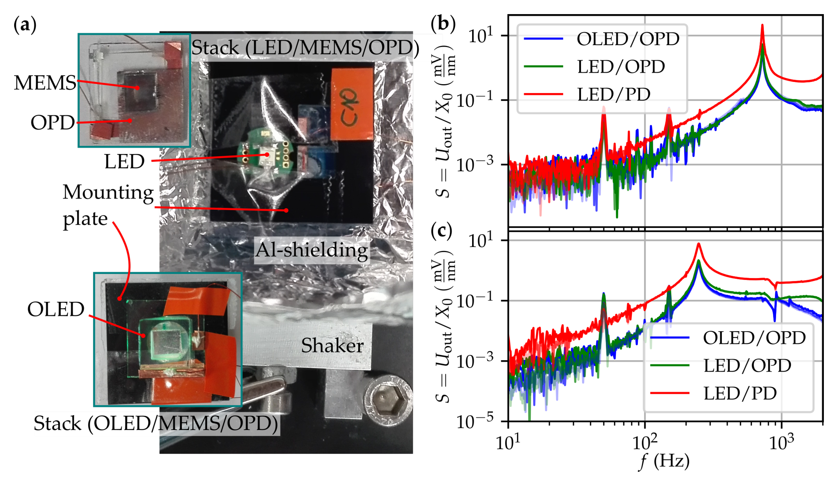
Prior to the HR and RR measurements, two identical types of MEMS chips differing only in their respective resonance frequency ( f 0 = 250 Hz and 620 Hz) were characterised in combination with both organic and inorganic optoelectronics. This way, the general performance differences between the chip types and optoelectronics types were investigated. The chips were characterised by recording the response to time-harmonic input vibrations with constant amplitudes X 0 = 4 , 8 , 16 nm (see Figure 2). The current supply of the (O)LED was set to a low 4 mA in order to prevent the decay of the OLED material. All combinations revealed similar performance with the purely inorganic optoelectronics yielding slightly larger output signals. This is mainly due to the performance of the OLED and the more difficult alignment using the organic components. Furthermore, the low-frequency amplitude for the MEMS with lower f 0 is obviously higher than of the one with higher f 0 .
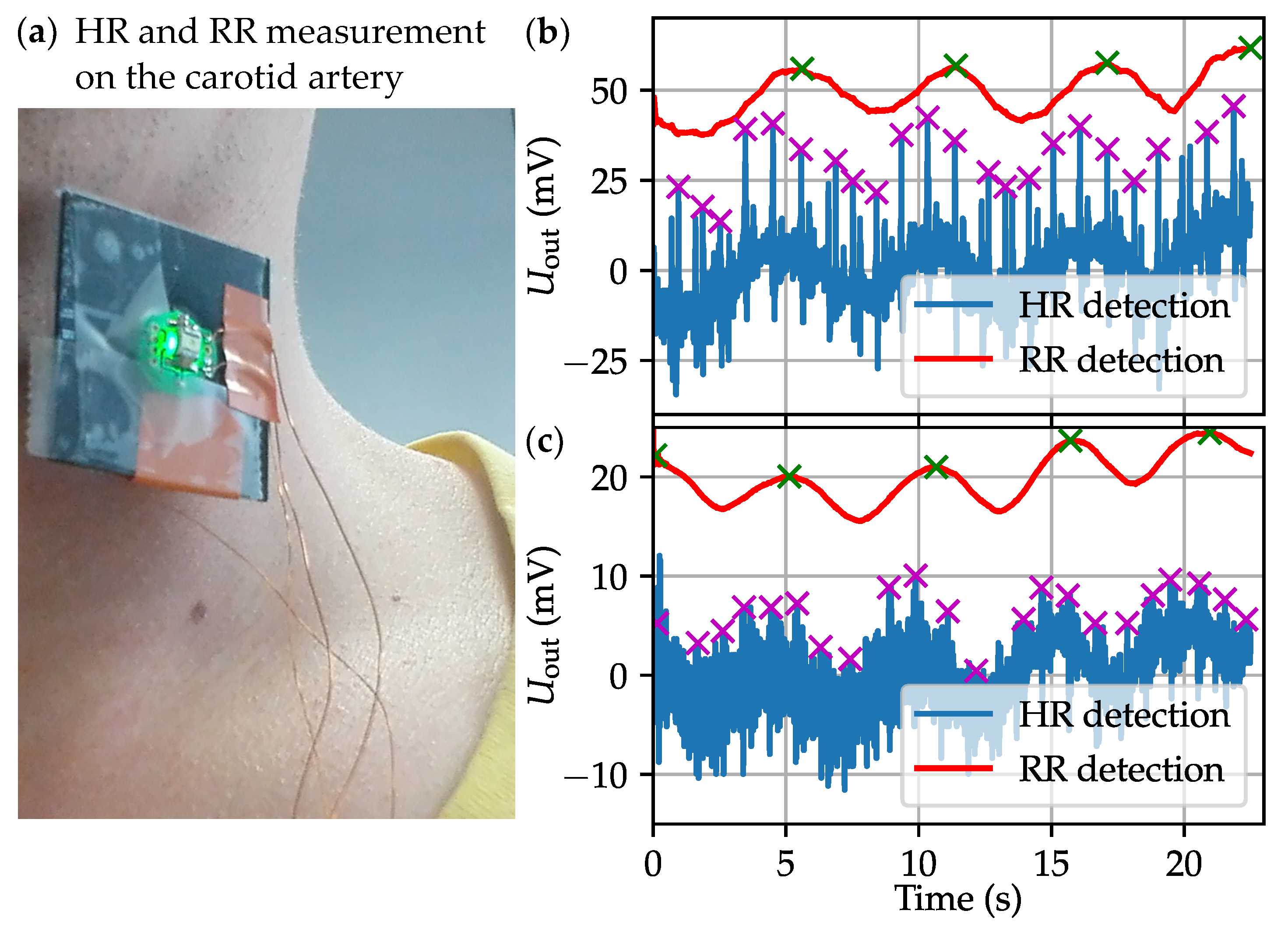
Therefore, the HR and RR measurements were performed with the MEMS with lower resonance frequency. The stack was placed onto the carotid artery and fixed with adhesive tape (see Figure 3a). The waveform the sensor picked up from the movement of the skin above the artery was recorded using an oscilloscope. First, the measurement was performed with the inorganic components. The results are depicted in Figure 3b. The waveform was evaluated with a python script in order to deliver the HR and RR. In the presented case, the HR was 63.6 min 1 and the RR 10.7 min 1 . The same measurement was performed with the same MEMS but with the organic optoelectronics. The results are shown in Figure 3c. It can be seen that, while HR and RR can also be extracted this way, the overall performance is a little worse. The reasons are again the difficult alignment and the performance of the OLED. The values obtained here for HR and RR are 60.3 min 1 and 11.6 min 1 , respectively.

4. Conclusions

It has been shown that it is possible to detect HR and RR using an inertial MEMS sensor and organic optoelectronics. This potentially enables low-cost, multi-function platforms for medical diagnostics, e.g., in combination with optical oximetry. For future developments it is necessary to improve the OLED lifetime in regard to the electrical driving power. This way, the optical output could be increased leading to a better sensitivity and signal-to-noise ratio.

Acknowledgments

This work was supported by the country of Lower Austria, the European Regional Development Fund (ERDF), the Austrian Science Fund (FWF project number TRP 226-N24) and the FFG project Cosiflex co-funded as part of the M-ERA.Net and the Austrian Ministry for Transport, Innovation and Technology (BMVIT).

Conflicts of Interest

The authors declare no conflict of interest. The founding sponsors had no role in the design of the study; in the collection, analyses, or interpretation of data; in the writing of the manuscript, and in the decision to publish the results.

References

  1. Bhansali, S.; Vasudev, A. MEMS for Biomedical Applications; Woodhead Publishing: Sawston, UK, 2012. [Google Scholar]
  2. Kaniusas, E. Biomedical Signals and Sensors I; Springer: Berlin, Germany, 2012. [Google Scholar] [CrossRef]
  3. Kaniusas, E. Biomedical Signals and Sensors II: Linking Acoustic and Optic Biosignals and Biomedical Sensors (Biological and Medical Physics, Biomedical Engineering); Springer: Berlin, Germany, 2015. [Google Scholar]
  4. Kainz, A.; Hortschitz, W.; Steiner, H.; Hong, Y.; Chen, C.; Zan, H.; Meng, H.; Sauter, T.; Keplinger, F. MOEMS Vibration Sensor with Organic Semiconductor Readout. Procedia Eng. 2016, 168, 1253–1256. [Google Scholar] [CrossRef]
  5. Hortschitz, W.; Steiner, H.; Stifter, M.; Kohl, F.; Kahr, M.; Kainz, A.; Raffelsberger, T.; Keplinger, F. Novel high resolution MOEMS inclination sensor. In Proceedings of the 2014 IEEE SENSORS, Valencia, Spain, 2–5 November 2014; pp. 1893–1896. [Google Scholar] [CrossRef]
  6. Kainz, A.; Hortschitz, W.; Steiner, H.; Schalko, J.; Jachimowicz, A.; Keplinger, F. Accurate analytical model for air damping in lateral MEMS/MOEMS oscillators. Sens. Actuators A Phys. 2017, 255, 154–159. [Google Scholar] [CrossRef]
  7. Middlemiss, R.; Samarelli, A.; Paul, D.; Hough, J.; Rowan, S.; Hammond, G. Measurement of the Earth tides with a MEMS gravimeter. Nature 2016, 531, 614–617. [Google Scholar] [CrossRef] [PubMed]
  8. Kainz, A.; Steiner, H.; Schalko, J.; Jachimowicz, A.; Kohl, F.; Stifter, M.; Beigelbeck, R.; Keplinger, F.; Hortschitz, W. Distortion-free measurement of electric field strength with a MEMS sensor. Nat. Electron. 2018, 1, 68. [Google Scholar] [CrossRef] [PubMed]
Figure 1. Schematic of the optomechanical MEMS transducer. Two identical grids of rectangular holes (one etched into a Si moving mass, one deposited onto glass) are placed on top of each other such that any movement of the seismic mass causes a modulation of the light flux passing through the device.
Proceedings 02 00715 g001
Figure 2. (a) Sensor components and stacks comprising (O)LED, MEMS and OPD. The MEMS chips were glued onto the OPDs such that the sensitive area and shutter area overlap. The (O)LEDs are fixed on top of the MEMS/OPD stack with a mounting plate in between to prevent electrodes from touching. The stacks were first characterised with the piezoelectric shaker. (b) results of MEMS with f 0 = 620 Hz in terms of the sensitivity S. (c) results of a MEMS with f 0 = 250 Hz. Each optoelectronics pairing was measured for three differend values of X 0 accounted for by opacity of the lines.
Proceedings 02 00715 g002
Figure 3. (a) Sensor stack placed on the cartoid artery for HR and RR measurement. (b) Result of a measurement with the inorganic sensor stack. The blue curve shows the waveform recorded with an oscilloscope already showing distinctive peaks corresponding to the heart rate (HR). These peaks were automatically identified and marked (magenta crosses). The respiration rate (RR) was extracted with a moving average filter applied onto the data of the blue curve leading to the red curve and green crosses. The curve was moved upwards by 50 mV for better visibility of both waveforms. (c) Result of a measurement with the organic sensor stack. It can be seen that the signal-to-noise ratio of the organic stack is not as good as for the inorganic one. This may be due to the difficult alignment of the sensor components. Nevertheless, HR and RR both were detected.
Proceedings 02 00715 g003
Publisher’s Note: MDPI stays neutral with regard to jurisdictional claims in published maps and institutional affiliations.