Proceeding Paper

Responsitivity Measurement of a Lorentz Force Transducer for Homogeneous and Inhomogeneous Magnetic Fields †

1
Department for Integrated Sensor Systems, Danube University Krems, Wiener Neustadt 2700, Austria
2
Institute of Sensor and Actuator Systems, TU Wien, Vienna 1040, Austria
*
Author to whom correspondence should be addressed.
Presented at the Eurosensors 2018 Conference, Graz, Austria, 9–12 September 2018.
Proceedings 2018, 2(13), 843; https://doi.org/10.3390/proceedings2130843
Published: 3 December 2018
(This article belongs to the Proceedings of EUROSENSORS 2018)

Abstract

:
This paper reports a MEMS gradiometer consisting of two independent, laterally oscillating masses on a single chip with integrated optical readout featuring a responsitivity of 35V/T at resonant operation. The symmetrical design of the two masses offers high accuracy and low cost by using conventional MEMS batch fabrication technology. The sensing principle is based on lateral displacement of the masses actuated by Lorentz forces which modulates a light flux passing through a stationary mask and the moving mask integrated in the masses. Phase and intensity detected by photodiodes reveal information about the uniformity of an external applied magnetic field, hence, enables the measurement of gradient-, homogeneous- and offset gradient magnetic fields.

1. Introduction

Magnetic field sensors based on microelectromechanical systems (MEMS) are advantageous in terms of small design, low power consumption, high sensitivity and reduced fabrication cost. Most of these sensors are resonantly excited oscillators utilising the Lorentz force principle. This combines the advantages of magnitude amplification and large dynamic measurement range. MEMS magnetic field sensors have their potential application in telecommunications, navigation, non-destructive testing [1], dipole characterisation (e.g., CERN [2]) and magnetic resonance tomography [3].
The proposed MOEMS gradiometer features light flux modulation through static and deflectable gratings and an optical readout which decouples the sensing part from the electronic components [4,5]. Furthermore, a promising high sensitivity with the optical readout was achieved and reported in [6]. Such a gradiometer offers an attractive non-destructive testing method for the steel industry, e.g., production of steel strips for the automotive industry, by detecting inhomogeneities, and, hence, guaranteeing quality standards.

2. Sensing Principle

Two identical laterally movable silicon (Si) masses were designed and accomplished as a single MEMS device. Both masses are structured with optical gratings and gold conductor paths at the masses’ outermost edges which enables Lorentz force excitation. A glass carrier consisting of static gratings is aligned and bonded with the Si die. The sensing principle is based on detection of modulated light flux by relative in-plane movement from the stencil masses and fixed glass mask. The sensor is capable of distinguishing between gradient and homogeneous magnetic fields by either opposed or same directional oscillation of the masses, respectively. Therefore, the phase difference of the output signal is either 0° for gradient fields or 180° for homogeneous fields.
The sensor chip, assembled in a stack including LEDs, photodiodes, and corresponding electronics is depicted in Figure 1. This compact setup guarantees improved alignment of all components and reproducibility of future measurements.

3. Measurement Set-Up

The sensor stack was investigated in two different arrangements at ambient pressure and the sensor’s resonance fR1350 Hz. Figure 2 depicts the measurement setups to characterise the sensor within (Figure 2a) a homogeneous magnetic field generated by coils in Helmholtz configuration and (Figure 2b) a magnetic gradient field ∇B produced by antisymmetric placement of the neodymium magnets. The magnets are mounted on linear stages (PLS-85, Micos SMC Corvus ECO Positioning Controller) to establish different ∇B by changing the distance dMagnet. The inset of Figure 2b illustrates a schematic of utilised devices. A Keithley current source (model 6221) provides the excitation for the sensor’s masses and, hence, the detected and amplified modulated light flux is acquired with lock-in amplifiers (SR830, SR865).

4. Results

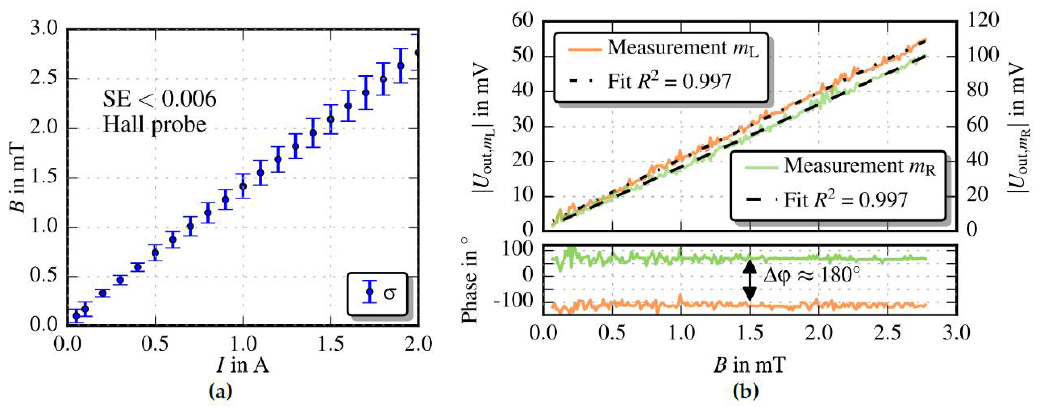
The occurring B-field created by the Helmholtz coils was first measured by a Hall probe (Figure 3a) within an area of 20 mm2 resulting in a standard error of SE < 0.006. Figure 3b depicts the sensor’s output signals referred to the applied homogeneous field. A responsitivity of 19 V/T and 35.7 V/T for mL and mR, respectively, was extracted from the linear fit functions. Although the masses are identically designed and fabricated, the output signals deviate about Uout,mR ≈ 1.8Uout,mL. This might be caused due to fabrication tolerances and variations/defects in the current conducting paths. The single current feeder is divided into two parallel paths shortly before it accesses the masses and is rejoined afterwards. Deviation of the leads’ conductivity across the masses results in an asymmetric partition of the current and, thus, diverging magnitude of mass deflection in a homogeneous magnetic field. Nevertheless, the measured phase difference of 180emphasise mass deflection in the same direction which denotes such a homogeneous field.
Figure 4 a depicts the measured perpendicular part of the flux density that occurs between the Nd magnets, characterised by a Hall probe. The responsitivity was extracted from the fit function and is 20.3 V/T and 35.6 V/T for mL and mR, respectively ( Figure 4 b). Again, the output signals deviate by a factor of ≈ 1.8. The phase difference is almost zero, indicating that both masses deflect in the opposed direction and, thus, a gradient field is present. Due to alignment offset between the masses’ and the glass’s gratings, the detected light flux deviates resulting in ∆ϕ = 0°. The gradient was calculated from the measured flux densities BmLUout,mL and BmRUout,mR and the fixed distance ∆x of the masses as
B | B m L B m R | Δ x
Further investigations reveals a noise equivalent magnetic resolution of 5 µT/Hz measured at fR and a quality factor of 334 extracted via the −3 dB bandwidth method from the sensor’s transfer function.

5. Conclusions

A compact magnetic field sensor with optical readout is reported, capable of measuring both gradient and homogeneous B-fields. Even though the masses’ responsitivity differs, the sensor’s output signal shows an appropriate linear behaviour regarding the B-field dependency. Further advancement in sensor design and fabrication, i.e., separated current leads and more accurate mask alignment shall harmonise the masses’ responsitivity and suppresses non-uniform light flux offset, respectively.

Author Contributions

M.K., M.S., W.H. and H.S. carried out the measurements, design and modeling. G.K. designed the electronic equipment and assembled the sensor stack. J.S were responsible for manufacturing the device chip, while A.K and F.K. supported the measurements and the design of the devices.

Acknowledgments

This work was supported by the country of Lower Austria, the Austrian Science Fund (FWF, project P 28404-NBL) and the prototype funding program PRIZE (project P1621687) of the Austria Wirtschaftsservice Gesellschaft mbH (aws).

Conflicts of Interest

The authors declare no conflict of interest.

References

  1. Herrera-May, A.; Soler-Balcazar, J.; Vázquez-Leal, H.; Martínez-Castillo, J.; Vigueras-Zuñiga, M.; Aguilera-Cortés, L. Recent Advances of MEMS Resonators for Lorentz Force Based Magnetic Field Sensors: Design, Applications and Challenges. Sensors 2016, 16, 1359. [Google Scholar] [CrossRef] [PubMed]
  2. Stifter, M.; Steiner, H.; Hortschitz, W.; Sauter, T.; Glatzl, T.; Dabsch, A.; Keplinger, F. MEMS micro-wire magnetic field detection method@CERN. IEEE Sens. 2015, 7, 1–4. [Google Scholar] [CrossRef]
  3. Dabsch, A.; Rosenberg, C.; Stifter, M.; Keplinger, F. MEMS cantilever based magnetic field gradient sensor. J. Micromech. Microeng. 2017, 27, 960–1317. [Google Scholar] [CrossRef]
  4. Hortschitz, W.; Steiner, H.; Stifter, M.; Kainz, A.; Kohl, F.; Siedler, C.; Schalko, J.; Keplinger, F. Novel MOEMS Lorentz Force Transducer for Magnetic Fields. Procedia Eng. 2016, 168, 680–683. [Google Scholar] [CrossRef]
  5. Hortschitz, W.; Steiner, H.; Sachse, M.; Stifter, M.; Kohl, F.; Schalko, J.; Jachimowicz, A.; Keplinger, F.; Sauter, T. Robust Precision Position Detection with an Optical MEMS Hybrid Device. IEEE Trans. Ind. Electron. 2012, 59, 4855–4862. [Google Scholar] [CrossRef]
  6. Hortschitz, W.; Steiner, H.; Stifter, M.; Kohl, F.; Kahr, M.; Kainz, A.; Raffelsberger, T.; Keplinger, F. Novel high resolution MOEMS inclination sensor. In Proceedings of the IEEE SENSORS 2014, Valencia, Spain, 2–5 November 2014; pp. 1893–1896. [Google Scholar] [CrossRef]
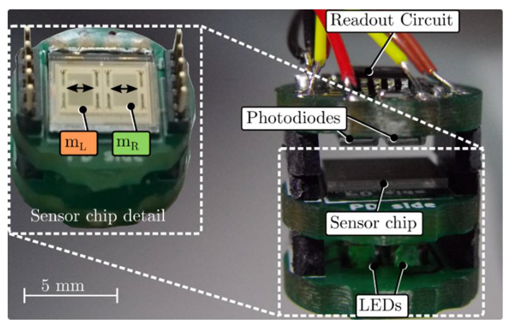
Figure 1. Assembled stack including a readout circuit, photodiodes (PD), sensor chip, and LEDs. The light flux is modulated by relative in-plane movements of the Si masses mL and mR, actuated by Lorentz forces, and the stationary glass frame. The fixed glass mask features vapor deposited Cr arrays of apertures. Hence, the PDs receive the modulated light passing through the masses and glass mask. The on-board electronics include LEDs driver and two transimpedance amplifiers (TIA) to convert the signals detected by the PD into an amplified output voltage. A magnetic field perpendicular to the current carrying masses introduces a force which induces a in-plane oscillation. When both masses deflect in the same direction, one mass suppresses light by closing the apertures whereas the other mass opens the apertures.
Proceedings 02 00843 g001
Figure 2. (a) Helmholtz configuration to characterise the sensor within a homogeneous magnetic field. (b) Measurement setup to realise a magnetic gradient field. The sensor stack is centered between two neodymium magnets which are fixed onto linear stages. The distance between the magnets dMagnet and the sensor stack is gradually changed to generate different |∇B|.
Proceedings 02 00843 g002
Figure 3. (a) The generated magnetic field in dependency of the coil current, characterised by a Hall probe (Teslameter, AS-NTM-2)). (b) Sensor output signals depending on the applied B-field. A phase difference of 180° denotes that both masses oscillates in the same direction which is equal to a unidirectional B-field.
Proceedings 02 00843 g003
Figure 4. (a) Depicts a few selected gradient fields which occurs in the vicinity of the sensor’s masses, measured by a Hall probe and the total amount of measured ∇B in dependency of dMagnet (inset). The masses’ sensing areas are indicated orange and green for mL and mR, respectively. (b) Sensor’s output signals, where a phase difference of 0 denotes opposed oscillation of the masses and, hence, a present gradient field (obtained with Equation (1)).
Proceedings 02 00843 g004
Publisher’s Note: MDPI stays neutral with regard to jurisdictional claims in published maps and institutional affiliations.