Proceeding Paper

Characterization of a Micro-Opto-Mechanical Transducer for the Electric Field Strength †

1
Department for Integrated Sensor Systems, Danube University Krems, 2700 Wiener Neustadt, Austria
2
Institute of Sensor and Actuator Systems, TU-Wien, 1040 Vienna, Austria
*
Author to whom correspondence should be addressed.
Presented at the Eurosensors 2018 Conference, Graz, Austria, 9–12 September 2018.
Proceedings 2018, 2(13), 855; https://doi.org/10.3390/proceedings2130855
Published: 21 November 2018
(This article belongs to the Proceedings of EUROSENSORS 2018)

Abstract

:
We report on a new optical sensing principle for measuring the electric field strength based on MEMS technology. This method allows for distortion-free and point-like measurements with high stability regarding temperature. The main focus of this paper rests on an enhanced measurement set-up and the thereby obtained measurement results. These results reveal an improved resolution limit and point to the limitations of the current characterization approach. A resolution limit of 222 V/m was achieved while a further improvement of roughly one order of magnitude is feasible.

1. Introduction

The reliable, highly localized and distortion-free measurement of the electric field (E-field) strength is of great interest for many scientific fields and industry. It can be used for atmospheric science, meteorology, or as instrument for warning from immanent electrostatic discharges in production lines for highly integrated electronic components. Furthermore, it is also urgently needed in the energy industry to assure the health and safety of personnel in the vicinity of high-voltage systems [1]. State-of-the-art sensors, however, are not capable of such measurements at all or just under considerable expense. Most of these sensors can not be miniaturized or are simply too expensive to be deployed in large numbers.
Our new type of sensor enables these measurements [2,3]. It is based on a micro-opto-electro-mechanical system (MOEMS) including a readout based on fiber optics. This allows for a galvanically separated, highly localized measurement of the electrical field strength while limiting the field distortion to a minimum. The measurement principle relies on the charge separation, due to the E-field E0, inside the conductive parts of the MOEMS. This charge separation implies, in combination with E0, electrostatic forces Fes acting on a deflectable grid of openings (compare Figure 1). The deflection is transferred into a variation of a light flux which is introduced perpendicularly through the MOEMS. Note that the force is proportional to E02 which leads to Fes having twice the frequency of E0.

2. Measurement Set-Up
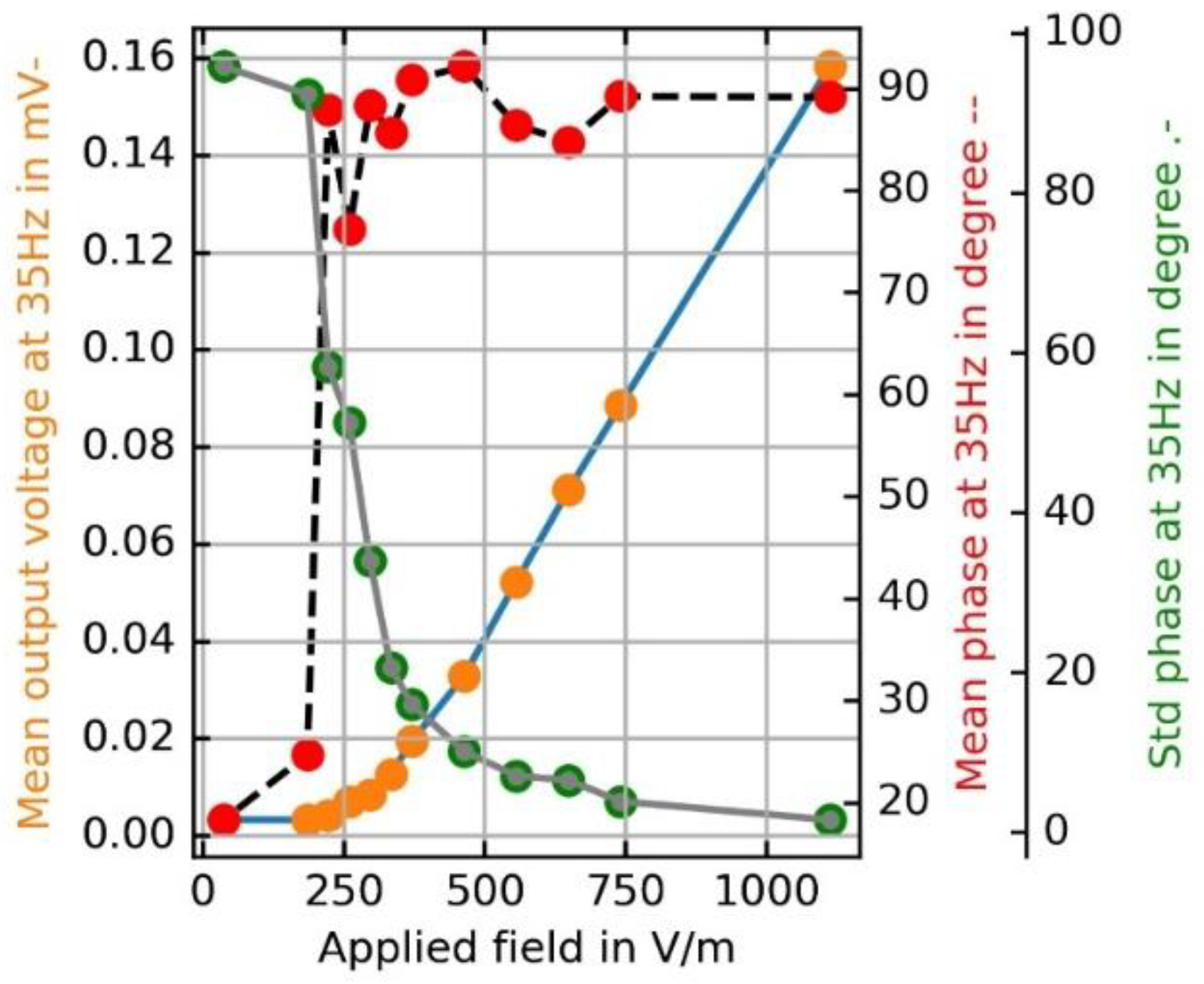
In contrast to the setup previously used and reported, e.g., in [2], the new set-up for characterizing the MEMS chips features a better and more reproducible positioning of the chip in relation to the light path axis. Additionally, a higher LED current of 50 mA and, therefore, larger light flux through the structure was used. In addition, larger field plates were implemented which results in a more homogeneous field around the chip. The enhanced measurement setup is depicted in Figure 2.
The correct mechanical function and transfer characteristics of these chips were tested previously under a micro-system analyzer MSA400 from Polytec. The electric field was produced by applying a voltage amplified with a dual-channel signal amplifier Model-9200A from Tabor Electronics. In the current configuration the output signal of a waveform generator 33500B from Keysight was used as input for the amplifier 9200A.
An LED528EHP from Thorlabs was used as light source due to its relatively low viewing half angle of 9° and its output power of 7 mW at 20 mA DC forward current. The LED was operated with an DC current of 50 mA which was supplied by a custom-built current source. The photo-current from the OSD15-E photodiode, introduced by the modulated light flux was amplified with an transimpedance amplifier (TIA) built using an OPA404. The output voltage of this TIA was recorded with an SR830 lock-in amplifier from Stanford Research. All measurements were performed fully automated, controlled by a Raspberry Pi micro-computer enabling also all necessary post- processing and visualization.

3. Results

The values for the mechanical resonance frequency, the stiffness, the damping, and the mass were obtained from measurements on a custom made shaker system and were determined to be f0 = 592 Hz, c = 6.19 N/m, d = 4.08 × 10⁻⁵ kg/s, m = 4.48 × 10⁻⁷ kg, respectively. The measurement results depicted in Figure 3 show the resonance peak at half of the mechanical resonance frequency.
Figure 4 depicts the magnitude of the mean output voltage as well as the mean values and the standard deviation of the phase values gained at 35 Hz. It clearly can be observed that with the improved setup, a resolution of 222 V/m was achieved.

4. Conclusions

A new and improved setup for characterizing MOEMS E-field sensors was presented. This setup enables more accurate measurements and, thus, more reliable characterisations due to its precise and robust fixation of the MOEMS chip and the enlarged space between the larger field plates. The resolution of the sensor was calculated from the magnitude and the phase information to be SRes = 222 V/m.

Author Contributions

W.H., G.K. and A.K. conceived, designed and performed the experiments; W.H., M.S., M.K. and H.S. analyzed the data; J.S. contributed in fabricating the devices; W.H. and F.K. wrote the paper.

Acknowledgments

This work was supported by the country of Lower Austria (NÖ), the European Regional Development Fund (ERDF) and the Austrian Science Fund (FWF project number P 28404-NBL).

Conflicts of Interest

The authors declare no conflict of interest. The founding sponsors had no role in the design of the study; in the collection, analyses, or interpretation of data; in the writing of the manuscript, and in the decision to publish the results.

References

  1. DIRECTIVE 2013/35/EU. Of the European Parliament and of the Council, 26 June 2013, on the minimum health and safety requirements regarding the exposure of workers to the risks arising from physical agents. Off. J. Eur. Union 2013, 179, 1. [Google Scholar]
  2. Kainz, A.; Steiner, H.; Schalko, J.; Jachimowicz, A.; Kohl, F.; Stifter, M.; Beigelbeck, R.; Keplinger, F.; Hortschitz, W. Distortion-free measurement of electric field strength with a MEMS sensor. Nat. Electron. 2018, 1, 68–73. [Google Scholar] [CrossRef]
  3. Hortschitz, W.; Steiner, H.; Stifter, M.; Kohl, F.; Kahr, M.; Kainz, A.; Raffelsberge, T.; Keplinger, F. Novel high resolution MOEMS inclination sensor. In Proceedings of the IEEE Sensors, Valencia, Spain, 2–5 November 2014; pp. 1889–1892. [Google Scholar]
Figure 1. (a) Forces and field lines of a conducting sphere with radius R in an external field Eex. The electric field polarizes the sphere. Oppositely charged regions of the surface of the sphere experience an electrostatic force Fes while maintaining polarization, (b) Polarization of different conductive domains of a schematic MEMS sensor and the resulting net force. (c,d) 3D-schematics of the key components, incorporating the openings for the optical readout, (e) Scanning electron microscope (SEM) image of a chip taken during fabrication depicting the key elements in the device layer.
Proceedings 02 00855 g001
Figure 2. Photograph showing the measurement set-up for characterization of the transducer between an LED and a photo-diode. The transducer in a chip-holder is inserted into the 3D-printed blue colored body which serves also as spacer and fixation for the field plates.
Proceedings 02 00855 g002
Figure 3. Measurement results for exciting the sensor with different field-strengths, also revealing the first two mechanical resonances. The resolution limit was gained from magnitude and phase information and is equivalent to 222 V/m (compare Figure 4).
Proceedings 02 00855 g003
Figure 4. Evaluation of mean value and standard deviation from magnitude and phase information revealing the resolution limit of 222 V/m (at 35 Hz, far below the resonance).
Proceedings 02 00855 g004
Publisher’s Note: MDPI stays neutral with regard to jurisdictional claims in published maps and institutional affiliations.

