Proceeding Paper

Microwave Oscillator Design for a SRR Based Biosensor Platform †

Department for Integrated Sensor Systems, Danube University Krems, 3500 Krems, Austria
*
Author to whom correspondence should be addressed.
Presented at the Eurosensors 2018 Conference, Graz, Austria, 9–12 September 2018.
Proceedings 2018, 2(13), 865; https://doi.org/10.3390/proceedings2130865
Published: 21 November 2018
(This article belongs to the Proceedings of EUROSENSORS 2018)

Abstract

:
A sensor for biomedical markers based on a split ring microwave resonator (SRR) was developed. The surface of the microwave resonator is covered with receptors that specifically bind to the target proteins where the local permittivity is changed. The resonator is part of a microwave oscillator circuit. Changes in the local permittivity caused by coupling of the target proteins result in a change of oscillator frequency which can be easily and accurate measured with high sensitivity.

1. Introduction

Nowadays split ring resonators (SRRs) are mainly used in meta-material research. The problem of low coupling of natural materials to the magnetic field of electromagnetic waves can be overcome by using metamaterials that mimic magnetism at high frequencies. For the microwave range, a recipe was suggested by Pendry in which he predicted that a pair of concentric split-ring resonators (SRRs) with subwavelength dimensions and facing in opposite directions would give rise to an effective permeability different than unity [1]. The magnetic response (which is due to electronic spin states) in naturally-occurring materials diminishes at frequencies higher than a few gigahertz. Moreover, there are no free magnetic monopoles, and thus it is not feasible to obtain a magnetic plasma as we can accomplish with electrons. Therefore, it is indeed a challenging issue to achieve any magnetic response in the microwave frequencies and higher, let alone more extreme values like negative permeability. Recently, however, the emergence of metamaterial research has fundamentally altered the situation. In metamaterials that consist of artificial subwavelength structures with tailored properties, the magnetic response is not limited anymore to the electronic spin states of individual atoms. Instead, magnetism can be achieved even in optical frequencies by specially designed “meta-atoms”—functional units of the metamaterial that are smaller than the wavelength. Therefore, artificial magnetism is possible in metamaterials as long as the magnetic field component of the incident electromagnetic wave can interact effectively with the “meta-atoms” [2]. This kind of structures forming artificial atoms is well suited for sensor applications because of its strong interaction with electromagnetic fields and its achievable high quality factor Q.

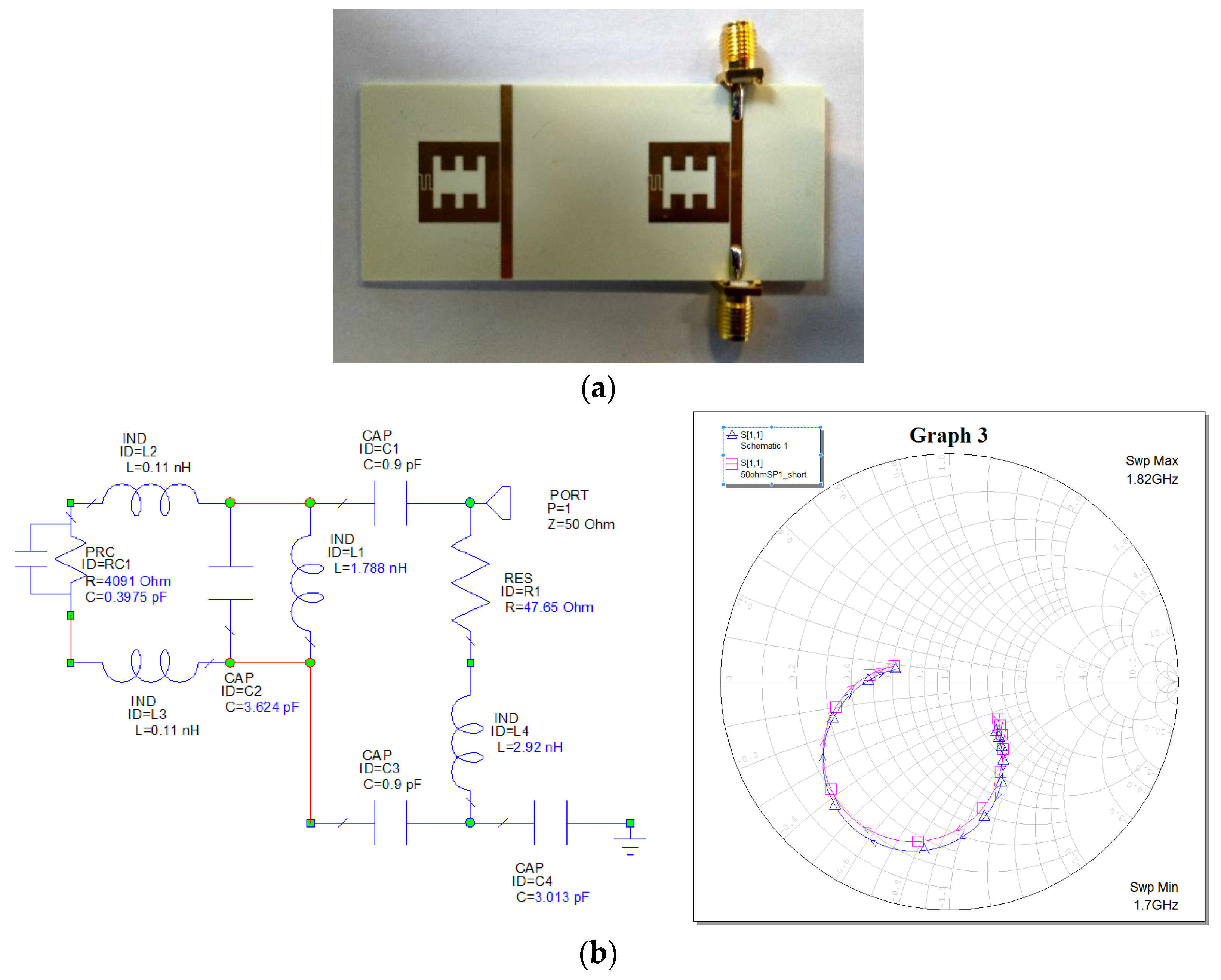
2. Biosensor Based on High Q Microwave SRRs

A biosensor based on microwave split ring resonators is introduced. A microwave oscillator which is nearly independent from the impedance of the load and the termination network was designed and simulated. In principle, the biosensor will consist of two identical SRR structures which are connected to two independent microwave oscillator circuits (Figure 1a). One of the SRRs will be used for sensing the other one is the reference SRR. The oscillator signals are mixed and low pass filtered where the difference frequency will be proportional to the amount of target molecules. The sensing layer is inject printed onto the gold surface of the SRR and allows therefore a costless and easy adaptable sensor design [3].
The response of a metallic ring to the external magnetic field is purely inductive and non-resonant. To introduce resonance behavior and enhance the magnetic response, capacitance can be purposely introduced by a gap in the ring structure. A gap in the metallic ring prevents the formation of a complete circular current, and electric charges accumulate across the gaps. In a single SRR, the accumulated charges around the gap induce an electric dipole moment, which overshadow the magnetic dipole moment by accurate design. With both capacitance and inductance, the SRR is a resonant element which can be used for resonant sensing applications. A design of a SRR with high quality factor Q was introduced in [4] and is sketched in Figure 1a,b together with its equivalent circuit.
For the simulation of the microwave oscillator, a lumped element equivalent circuit for the SRR was extracted from the measured data. The fit of the equivalent circuit to the SRR measurements was optimized by LMS methods (Figure 1b). The oscillator circuit (Figure 2a) was carefully designed and optimized for maximum output power and load independency on the in- and output port which is validated by the simulated in- and output stability circuits (Figure 2b) where for in- and output impedances laying inside the circles the circuit is potential unstable. The oscillator stability circles cover at resonance frequency nearly the whole impedance spectrum of the SRR and therefore the impedance of the load network (SRR) and the impedance of the termination network will not influence the instability of the oscillator.
The oscillator was designed with a low noise silicon bipolar RF transistor BFP540 in common-base configuration. A negative resistance of the transistor at the input and output terminal which is necessary for oscillator operation is incorporated by the inductivity L1 connected to the transistor base. The value of L1 was chosen to get a stability factor K < 1 at resonance frequency of the SRR. The value of the output voltage/output power can be optimized by adjusting the value of L1 (Figure 3a) which was simulated using LTSpice [5]. If the inductivity of L1 exceeds 12 nH the oscillation of the circuit stopped because the resonance condition is no longer fulfilled. It was also found out that the harmonic distortion of the oscillator output signal has a dependency on the inductivity L1. With the simulation tool LTSpice a FFT analysis of the output waveform was done which indicates that especially the 3rd harmonic overtone based on its power is relevant for distortion. In Figure 3b the ratio between the fundamental frequency and the 3rd harmonic is given. It is shown, that the ratio P0/P3 is increasing with higher values of L1. Therefore the inductivity L1 should be chosen as large as possible for high output power and low harmonic distortion but with the limitation that the resonance condition is fulfilled for all operating conditions.
To proof the quality of the oscillator circuit and the SRR, the phase noise was measured and is about −90 dBc/Hz for Δf = 10 kHz (Figure 3c). The output power of the SRR oscillator is about +6 dBm for L1 = 5 nH and a supply voltage of Ub = 4 V.

Acknowledgments

The authors would like to thank the NÖ Forschungs- und Bildungsges.m.b.H. (NFB) for financially supporting the project (LSC13-023).

References

  1. Pendry, J.B.; Holden, A.J.; Robbins, D.J.; Stewart, W.J. Magnetism from conductors and enhanced nonlinear phenomena. IEEE Trans. Microw. Theory Technol. 1999, 47, 2075–2084. [Google Scholar] [CrossRef]
  2. Cai, W.; Shalaev, V.; Paul, D.K. Optical metamaterials: Fundamentals and applications. Phys. Today 2010, 63, 57. [Google Scholar]
  3. Melnik, E.; Muellner, P.; Mutinati, G.C.; Koppitsch, G.; Schrank, F.; Hainberger, R.; Laemmerhofer, M. Local functionalization of CMOS-compatible Si3N4 Mach-Zehnder interferometers with printable functional polymers. Sens. Actuators B Chem. 2016, 236, 1061–1068. [Google Scholar] [CrossRef]
  4. Wellenzohn, M.; Brandl, M. A Theoretical Design of a Biosensor Device Based on Split Ring Resonators for Operation in the Microwave Regime. Procedia Eng. 2015, 120, 865–869. [Google Scholar] [CrossRef]
  5. Engelhardt, M. LTSpice; Linear Technology, Inc.: Milpitas, California, USA, 2015; Available online: http://www.linear.com (accessed on 1 April 2018).
Figure 1. (a) SRR design, (b) Lumped element equivalent circuit of the SRR and matching between the equivalent circuit and the measurement.
Proceedings 02 00865 g001
Figure 2. (a) Schematic of the microwave oscillator circuit. (b) Input and output stability circuits of the oscillator at f0 = 1.7 GHz.
Proceedings 02 00865 g002
Figure 3. (a) Oscillator output power in dependency of L1. (b) Harmonic distortion in dependency of L1. (c) Measured oscillator phase noise (L1 = 5 nH, Ub = 4 V).
Proceedings 02 00865 g003
Publisher’s Note: MDPI stays neutral with regard to jurisdictional claims in published maps and institutional affiliations.

