Proceeding Paper

A 3-Degree-of-Freedom MEMS Mirror with Controllable Static and Dynamic Motion for Beam Steering †

Department of Electrical and Computer Engineering, University of Manitoba, Winnipeg, MB R3T 2N2, Canada
*
Author to whom correspondence should be addressed.
Presented at the Eurosensors 2018 Conference, Graz, Austria, 9–12 September 2018.
Proceedings 2018, 2(13), 938; https://doi.org/10.3390/proceedings2130938
Published: 17 December 2018
(This article belongs to the Proceedings of EUROSENSORS 2018)

Abstract

:
A 3 Degree-of-Freedom (DOF) MEMS mirror is presented which can direct the light beam on an objective point and also operate in a continuous resonance 2 DOF mode. The micro-mirror is actuated by Lorentz force and has 4 actuators embedded in 4 sides of a square mirror. By enabling the actuators, different types of tilting and linear motion can be achieved. The micro-mirror is able to work in either static mode by applying dc current or dynamic mode by applying an ac current at the mirror resonance frequency. The mirror showed a maximum tilt angle of 14.5° and 20° for an input rms power of 2 mW in the resonance mode. A linear motion of 200 µm was achieved by 65 mW of dc power.

1. Introduction

Scanning MEMS mirrors have been developed for many systems including micro projectors [1], imaging, and catheters [2]. In some applications, the objective area needs to be scanned vertically and horizontally which requires the mirror to mechanically move in 2 or 3 dimensions. Multi-DOF MEMS mirrors have been developed to fulfill this requirement. In addition to scanning a pattern, focusing the light beam on an objective point is also desired for focal point alignment and depth scanning purposes [3].
Multi-DOF MEMS mirrors have been reported in two types of structures including gimballed [4] and gimbal-less [5] structures. Gimballed structures consist of inner and outer frames and the mirror is located inside the inner frame. Each frame tilts about one axis which is perpendicular to the tilt axis of the other frame. Gimballed structures work in two resonant modes known as fast and slow scan modes [6]. This type of structures has been reported with electrostatic [4], piezoelectric [7] and electromagnetic [6] actuation. There are benefits and drawbacks to each type of actuation. Electrostatically actuated MEMS mirrors are of high resonance frequency but require a large input voltage for tilting. For example, in MEMS mirror reported by ref [8], an input of 16.7 V was used per 1 µm of displacement. Comparing to the other types of actuations, Piezoelectric-actuated MEMS mirrors have less been reported due to the complexity in fabricating PZT material. Electromagnetically actuated gimballed structures have large tilt angle but are usually limited to two degrees of freedom [9]. This limit comes from the difficulty of aligning the magnetic field orientation with different directions of current.
In gimbal-less structures, the mirror is directly connected to a frame using several flexures. Electro thermally actuated gimbal-less MEMS mirrors have shown very good tilt angle in 3 degrees of freedom [5]. However, the generated heat on the flexures can cause problem in temperature-sensitive applications.
In this work, an electromagnetically actuated gimbal-less micro-mirror is reported. This mirror can tilt in two directions and move linearly in one direction. The simulation analysis of this design was previously reported in [10]. The impact of this mirror is having large amplitude of motion with respect to the consumed power in 3 directions, while possessing the ability to work in both resonance and static modes of motion.

2. Materials and Methods

2.1. Design

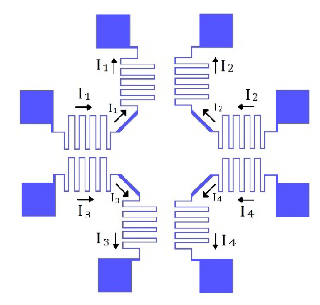
Figure 1 shows the schematic of the micro-mirror device. The square-shaped mirror is connected to a fixed frame using 4 flexures at its corners. An external magnetic field of 0.1 T was supplied by a permanent magnet. The magnetic field is oriented 45° with respect to the mirror sides. Each flexure has two conductors, allowing electrical current (I1, I2, I3, I4) on each side of the mirror to be individually controlled. Figure 2 shows the four coils and the possible current paths. Each flexure has two wires on it, carrying separate currents. For example, wires for I1 and I2 are on the top flexure in Figure 2. Therefore, all the four sides of the mirror can be individually actuated. The Lorentz force exerted on the flexures and mirror sides is governed by Equation (1).
F L o r e n t z = I l × B
where I is the current, l is the length of wire and B is the magnetic flux density. The different tilting modes are formed by changing the direction of current in wires passing through the mirror sides and flexures. Figure 1. a and b show the mirror tilting about ϕ and θ axis.

2.2. Fabrication

The MEMS mirror was fabricated out of a <100> silicon wafer. A layer of 1.5 µm silicon dioxide was grown on both sides of the wafer. The SiO2 on the backside of the wafer was patterned and the silicon on the patterned area was chemically etched in potassium hydroxide solution. A layer of 1.5 µm aluminum was deposited on the front side of the wafer and patterned to form the wires and mirror. Lastly, the patterns on the front side of the wafer was covered by a thick layer of photoresist and the structure was released from the back and front sides, using isotropic and anisotropic plasma etching processes. Figure 3 shows a fabricated MEMS mirror.

3. Results and Conclusions

The device was tested by shining a laser diode on the mirror and measuring the displacement of the reflected laser spot. The initial angle of incidence was 45° with respect to the normal of the mirror plane. An electrical current of 1–18 mA was applied.
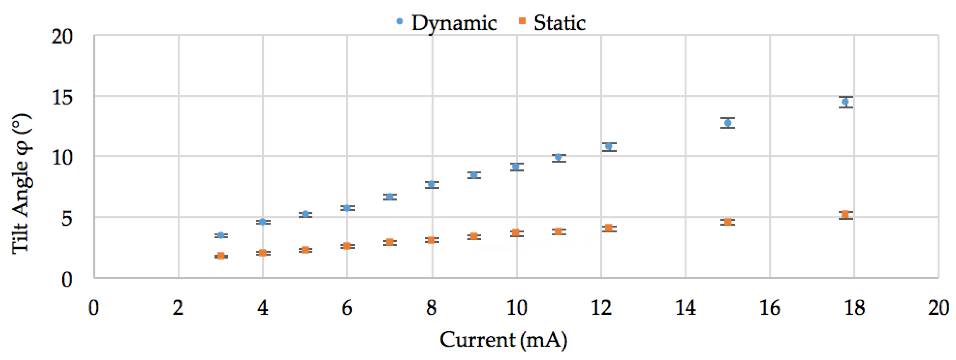
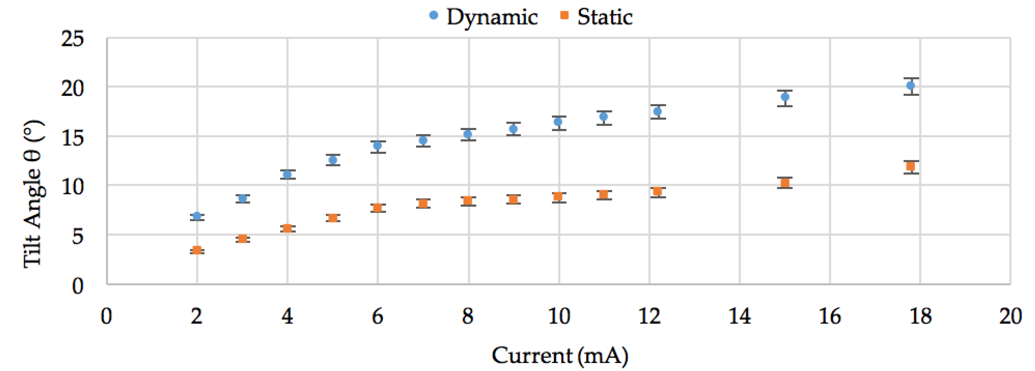
The static and dynamic modes were measured by applying dc and ac current. In the static mode, tilt angles of 5.1° in φ mode and 11.8° in θ mode were measured. In the dynamic mode, tilt angles of 14.5° in φ and 20° in θ were measured at 238 Hz and 244 Hz resonance frequencies respectively. The power consumption with an input current of 18 mA was 2 mW which caused a temperature rise of 15 °C on the flexures. The variation of tilt angles of φ and θ versus applied current are shown in graphs of Figure 4 and Figure 5 for static and dynamic actuations. The third mode of motion was operated by actuating all the 4 sides together. The mirror showed a linear motion of 200 µm with 65 mW of dc power.

Author Contributions

E.A., C.S. and B.P. conceived and designed the device and experiments; E.A. performed the experiments; R.S. contributed materials and analysis tools.

Acknowledgments

This research was financially supported by the Natural Sciences and Engineering Research Council (NSERC) of Canada and the University of Manitoba Graduate Fellowship (UMGF).

Conflicts of Interest

The authors declare no conflict of interest. The founding sponsors had no role in the design of the study; in the collection, analyses, or interpretation of data; in the writing of the manuscript, and in the decision to publish the results.

References

  1. Ma, J. Advanced MEMS-based technologies and displays. Displays 2015, 37, 2–10. [Google Scholar] [CrossRef]
  2. Aguirre, A.D.; Herz, P.R.; Chen, Y.; Fujimoto, J.G.; Piyawattanametha, W.; Fan, L.; Wu, M.C. Two-axis MEMS Scanning Catheter for Ultrahigh Resolution Three-dimensional and En Face Imaging. Opt. Express 2007, 15, 2445–2453. [Google Scholar] [CrossRef] [PubMed]
  3. Hokari, R.; Hane, K. Micro-mirror laser scanner combined with a varifocal mirror. Microsyst. Technol. 2012, 18, 475–480. [Google Scholar] [CrossRef]
  4. Hung, C.-L.A.; Lai, Y.-H.H.; Lin, T.W.; Fu, S.G.; Lu, S.-C.M. An electrostatically driven 2D micro-scanning mirror with capacitive sensing for projection display. Sens. Actuators A-Phys. 2015, 222, 122–129. [Google Scholar] [CrossRef]
  5. Morrison, J.; Imboden, M.; Little, D.C.T.; Bishop, D.J. Electrothermally actuated tip-tilt-piston micromirror with integrated varifocal capability. Opt. Express 2015, 23, 9555–9566. [Google Scholar] [CrossRef]
  6. Yalcinkaya, A.D.; Urey, H.; Brown, D.; Montague, T.; Sprague, R. Two-axis electromagnetic microscanner for high resolution displays. J. Microelectromech. Syst. 2006, 15, 786–794. [Google Scholar] [CrossRef]
  7. Baran, U.; Brown, D.; Holmstrom, S.; Balma, D.; Davis, W.O.; Muralt, P.; Urey, H. Resonant PZT MEMS scanner for high-resolution displays. J. Microelectromech. Syst. 2012, 21, 1303–1310. [Google Scholar] [CrossRef]
  8. Wei, Z.; Li, P.; Zhang, X.; Wang, Y.; Hu, F. InGaN/GaN micro mirror with electrostatic comb drive actuation integrated on a patterned silicon-on-insulator wafer. Opt. Express 2018, 26, 7672–7682. [Google Scholar] [CrossRef]
  9. Makishi, W.; Kawai, Y.; Esashi, M. Magnetic torque driving 2D micro scanner with a non-resonant large scan angle. In Proceedings of the TRANSDUCERS 2009—2009 International Solid-State Sensors, Actuators and Microsystems Conference, Denver, CO, USA, 21–25 June 2009; pp. 904–907. [Google Scholar] [CrossRef]
  10. Afsharipour, E.; Park, B.; Shafai, C. Large Tilt Angle Lorentz Force Actuated Micro-Mirror with 3 DOF for Optical Applications. Proc. Eurosensors 2017, 1, 351. [Google Scholar] [CrossRef]
Figure 1. Schematic of the MEMS mirror, blue arrow shows the direction of magnetic field B, red arrows show the directions of current, green circles show the directions of force. (a) The φ tilt mode. (b) The θ tilt mode.
Proceedings 02 00938 g001
Figure 2. The four current paths showed separately.
Proceedings 02 00938 g002
Figure 3. A fabricated mirror. Expanded view (left) shows the two conductor wires on the spring.
Proceedings 02 00938 g003
Figure 4. Angle of φ tilt mode vs. current. Red squares show the tilt angle with dc current, and the blue circles show the tilt angle with ac current of 238 Hz, using configuration of Figure 1a.
Proceedings 02 00938 g004
Figure 5. Angle of θ tilt mode vs. current. Red squares show the tilt angle with dc current, and the blue circles show the tilt angle with ac current of 244 Hz, using configuration of Figure 1b.
Proceedings 02 00938 g005
Publisher’s Note: MDPI stays neutral with regard to jurisdictional claims in published maps and institutional affiliations.