1. Introduction
In a fluid power system, the fluid (generally oil derived from a mineral source with suitable additives) must has to be considered as a real extended component interacting with the others. It carries out two important tasks: lubrication and power transmission. The main reason of failure is the degradation of the hydraulic oil caused by temperature, friction, contaminations by particles and presence of water. The failure involves a drop in machine reliability, a leakage of pollutant material and an expensive not planned stop machine. For this reasons, the real time monitoring of the oil ageing should be an issue.
The hydraulic oil is a system characterized by a large number of chemical-physical properties (viscosity, density, dielectric constant, oxidation level, acid grade, additives concentration, color, etc.) which change with the oil ageing.
Typically, oil samples are analyzed through portable systems or in laboratory using conventional methods and instrumentation (Brookfield viscometer, Karl Fischer method, spectroscopy (FTIR), thermal analysis (DSC), micro-analysis of particulate, analytical ferrography, etc.).
Starting from the evidence that hydraulic oil exhibits a strong and characteristic odor that becomes sour and putrid with ageing, our basic idea has been to find a correlation between the variation of the oil headspace and their ageing by using an indirect, easy and versatile technique based on thick film gas sensors. In literature, very few novel investigations related to this subject are present: various sensors for on-line lubricant oil monitoring [
1], water sensors in hydraulic oils [
2], instruments to analyze the headspace of lubricant oils (for example gas chromatograph, electronic nose) [
3], MOX sensors to detect diesel in lubricant oils [
4], etc. However there aren’t research works focused on the correlation between the headspace of hydraulic oil and its ageing detected through MOX sensors.
2. Materials and Methods
2.1. Hydraulic Test Bench
An hydraulic test bench was specifically developed to work continuously, rapidly ageing the oil, under controlled conditions also excluding the external agents contamination.
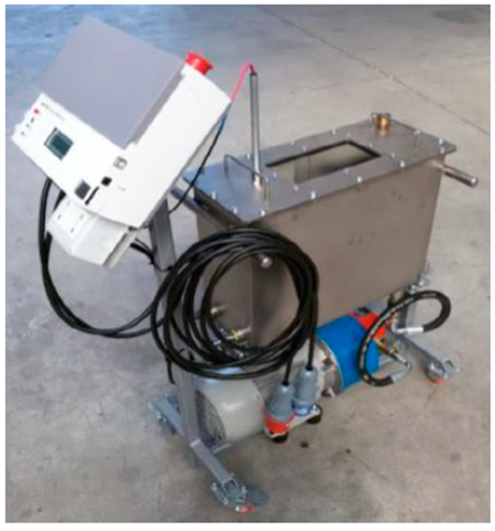
The realized test bench is shown in
Figure 1. It is composed of the following parts: an electronic control, an electric motor, a pump, a heat exchanger, a 30 L tank, a temperature sensor and a level one. As reported in the operating manual of a John Deere agrimotor, the complete oil change corresponds to 1500 working hours. For this reason, the sampling of the oil has been carried out with the test bench from 0 to 3000 h (steps of 250 h) to better understand the modifications of the oil properties due to ageing.
2.2. Gas Chomatographic Analysis
The analysis of volatile compounds in oil headspace samples has been performed by using a gas-chromatograph HP 6890 Series Plus, Agilent Technologies (Milano, Italy) and a mass spectrometer MSD 5973 Agilent Technologies as detector. The chromatograms have been obtained after extraction of volatile fraction through static head space using GC-MS technique which separates and identifies the single volatile compounds. The identification has been performed comparing the mass spectrum of each peak of the chromatogram with the mass spectra in data base Wiley 275.
2.3. Laboratory MOX Sensors System
To carry out the oil ageing characterization, a system based on an array of nanostructured semiconductor oxide gas sensors was expressly realized.
MOX sensors were prepared starting from the synthesis of semiconductor nanopowders via sol–gel route under atmospheric conditions. Thick films constituted by nanopowders were deposited through screen printing technique onto miniaturized alumina substrates, each one provided with a heater element and interdigitated electrodes. To print the sensing layers, a viscous paste was prepared by adding to the functional material an organic vehicle and a small amount of a bonding agent to promote the film adhesion to the alumina substrate. The films were then fired at 650 °C for 1 h in a muffle furnace [
5].
The sensors monitoring unit is constituted of a sealed chamber to lodge the MOX sensors, the electronic circuitry of each sensor, the main electronic control unit, the firmware, the software to record the sensor electrical signals in addition to a system to collect and carry the vapor oil through the sensor box.
The flow-through technique was used to test the electrical properties of the sensing layers. The measurement of conductance was carried out maintaining a flow rate of 0.5 L/min using synthetic air as carrier gas in dry conditions. Dynamical responses of sensing films were obtained in presence of mixture of air and oil volatile compounds. The sensor response is defined as ratio between the conductance in presence of the volatile compounds mixture and the conductance in air.
3. Results and Discussion
3.1. Hydraulic Test Bench
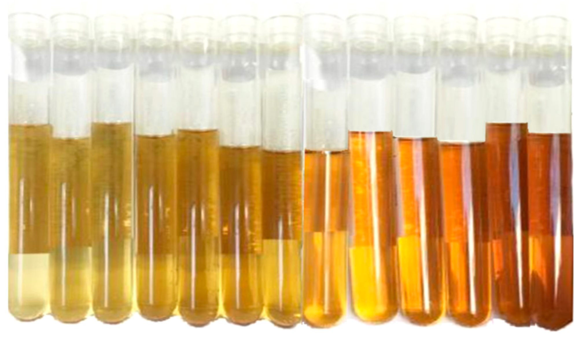
The oil samples, (oil type: JOHN DEERE–HY-GARD JDM J20C) was aged and collected using the hydraulic test bench. In the
Figure 2 the complete series of oil aged from 0 to 3000 h (steps of 250 h) is shown.
3.2. Gas Chomatographic Analysis
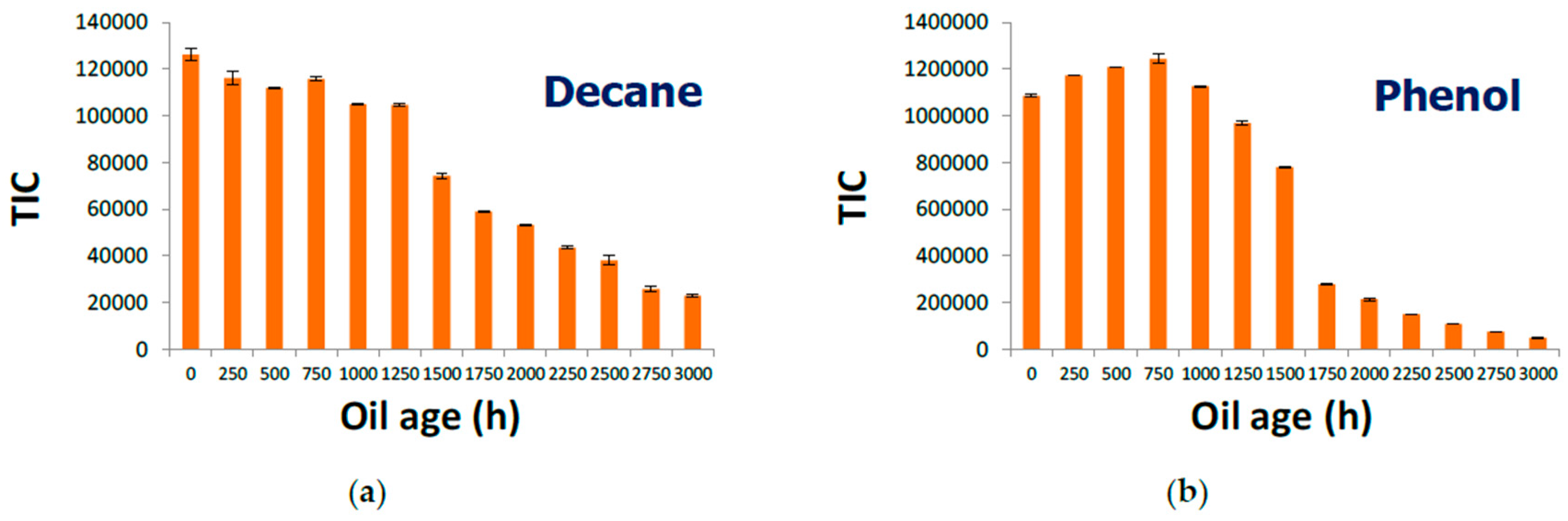
GC-MS measures of the oil samples’ headspace have highlighted the presence of 12 different compounds, among them aldehydes, ketones, alcohols, and aliphatic and aromatic hydrocarbons.
A decreasing in the GC responses over the time was observed for all the investigated compounds, being 2-methyl-1-propanol, 2-methyl-1-butanol 1-pentanol and phenol, the compounds for which a significant decrease was observed. As an example, the concentration of decane and phenol in the oil headspace during ageing are reported in
Figure 3.
3.3. Laboratory MOX Sensors System–Oil Ageing Characterization
A wide series of systematic measurements has been performed changing the working temperature of the sensors, the flow ratio between the carrier and the volatile compounds mixture and the measuring time to find the best working condition for characterizing the different aged oils. An example of dynamic response is reported in the
Figure 4a.
For all sensors, the response toward oil samples aged from 0 to 1500 h showed variation in the range of the experimental error. At about 1500 h of ageing, a sudden decreasing of sensors response occurred. This result is in agreement with GC analysis in which the decreasing of volatile compounds was highlighted in the same range of ageing. The result is also in agreement with oil change specifications reported in operating manual of a John Deere agrimotor. The described measurements have been carried out using oil samples at ambient temperature. Since the oil, in the usual working conditions, reaches an average temperature of 90 °C, the tests will be also performed on the heated oil samples with the aim to achieve higher degree of sensitivity among the different ageing times.
Author Contributions
A.F., A.B. and G.P.M. designed and realized the hydraulic test bench; A.F., S.M., M.C.C., conceived and designed the experiments and realized MOX sensors; F.B. and N.R. performed the GC analysis; A.F., S.M., and M.C.C. analyzed the data; A.F. wrote the paper.
Conflicts of Interest
The authors declare no conflict of interest.
References
- Mujahid, A.; Dickert, F.L. Monitoring automotive oil degradation: Analytical tools and onboard sensing technologies. Anal. Bioanal. Chem. 2012, 404, 1197–1209. [Google Scholar] [CrossRef] [PubMed]
- Zebing, M.; Zhao, J.; Xuan, W.; Wang, W.; Luo, J.; Xie, J. Distilling determination of water content in hydraulic oil with a ZnO/glass surface acoustic wave device. Microsyst. Technol. 2017, 23, 1841–1845. [Google Scholar] [CrossRef]
- Sepcic, K.; Josowicz, M.; Janata, J.; Selby, T. Diagnosis of used engine oil based on gas phase analysis. Analyst 2004, 129, 1070–1075. [Google Scholar] [CrossRef]
- Capone, S.; Zuppa, M.; Presicce, D.S.; Francioso, L.; Casino, F.; Siciliano, P. Metal oxide gas sensor array for the detection of diesel fuel in engine oil. Sens. Actuators B Chem. 2008, 131, 125–133. [Google Scholar] [CrossRef]
- Carotta, M.C.; Fioravanti, A.; Gherardi, S.; Malagù, C.; Sacerdoti, M.; Ghiotti, G.; Morandi, S. (Ti,Sn) solid solutions as functional materials for gas sensing. Sens. Actuators B Chem. 2014, 194, 195–205. [Google Scholar] [CrossRef]
| Publisher’s Note: MDPI stays neutral with regard to jurisdictional claims in published maps and institutional affiliations. |
© 2018 by the authors. Licensee MDPI, Basel, Switzerland. This article is an open access article distributed under the terms and conditions of the Creative Commons Attribution (CC BY) license (https://creativecommons.org/licenses/by/4.0/).

 ,
, 