Abstract
To enhance the performance and reliability of aircraft propulsion systems, an integrated bearing condition monitoring system is proposed. This intelligent bearing must have advanced health management capabilities to provide early warning of problems. In most commercial high-temperature applications, the sensing system is located externally due to lack of appropriate electronic devices that can function at high temperature. This paper presents the design and implementation of a self-powered sensing system for use in a high-temperature aircraft environment. The performance of the thermoelectric generator and energy availability to process acceleration data is shown from our laboratory tests based on realistic operating conditions.
1. Introduction
Self-powered sensing systems operating in harsh environments, especially at high temperatures, are of great interest to many industries. Real-time data collection from sensors and data analytics can be used to improve the performance and reduce maintenance costs in high temperature applications. Self-powered sensing systems consist of energy harvesters, sensors, electronics including amplifiers, Analog to Digital converters (ADC), processors, and boost converters. Most commercial sensing systems cannot be situated in a high temperature environment [1]. We aim to design a self-powered system for temperatures greater than C, but we are restricted by the available technology as few items that operate at this temperature exist. Operating temperatures for each component of the proposed self-powered sensing system is shown in Figure 1.
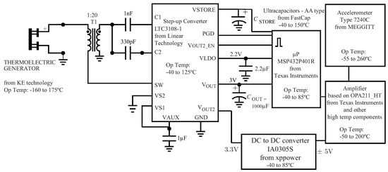
Figure 1.
Schematic of a self-powered sensing system. Operating temperature for each component is specified.
Due to the limited lifetime and regular replacements of batteries, an energy harvester can be replaced as a power source. Temperature variations exist within aerospace propulsion systems, and so are appropriate for powering sensor networks in these environments. These temperature variations cause a flow of heat between two surfaces, from which electrical energy can be harvested. A thermoelectric generator, which converts heat energy to electrical energy is a popular choice of energy harvesting compares to vibration, solar, and RF energy harvesting in high temperature environments [2]. Thermoelectric generators operate on the principle that, when the connected junctions of two dissimilar materials have a temperature difference, an electrical current is generated. Typically, the best performance of the thermoelectric generators is reached when one side of the thermoelectric module is in contact with forced air convection [3]. Skeleton module in which there is an electrically insulating base plate on one side and the other side is open can be a good alternative. If the base plate is attached to the colder side, it is easier to relieve the thermal stress in the module [4]. The power density of the commercial thermoelectric generators is in the range of 10 for a significant temperature gradient. In this paper we test a TEG to provide energy to record acceleration data from an accelerometer. The experimental set-up is shown in Section 2 and the system evaluation is expressed in Section 3.
2. Experimental set-up
TEG can be located near the bearing inside a jet engine, where there is an opportunity to place the hot side on a hot surface and use the circulating oil to cool down the cold side. In this study, the hot side of the TEG is exposed to a hot surface at temperatures simulating aero-engine conditions, a separate oil circulating system is exploited to cool the TEG, resulting in greater power generation. The challenge is in maintaining the temperature difference between the hot and the cold side of the TEG. To address this, we propose a commercial TEG [5] with an internal cooling system, shown in Figure 2. The proposed design consists of a TEG with its hot side on a heat source and Mobil Jet Oil II is circulated in the chamber on the cold side. A step-up converter is used to boost the output voltage of the TEG (when mV), and to store it in a high temperature AA-type ultracapacitor from FastCap (with rated capacitance equal to 32F and rated voltage of 1V). High temperature amplifier was designed for a piezoelectric accelerometer. Measurement data was collected with a microprocessor as a proof of the concept. This processor and the DC to DC converter will be replaced by high-temperature components as part of future development.
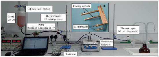
Figure 2.
Experimental set-up.
3. Methodology and results
Figure 3 shows temperature and voltage data from running the self-powered sensor network system in Figure 2. The charge current from the LTC3108-1 is 0.03mA (measured when V), and the total average current requirement of 60mA is measured during the acceleration data recording. is chosen equal to 1000F to fulfil the requirement of providing power for 5ms data processing with a voltage drop equal to 0.3V. By measuring the charge current from the LTC3108-1 and the current drawn from during the sleep state, the optimum duty cycle can be calculated. We can conclude that with this TEG at this given environment with the charged ultracapacitors we can record acceleration data with a sampling frequency equal to 20kHz for 5ms every 10sec.
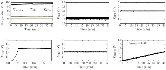
Figure 3.
Measured temperatures and voltages. Five ultracapacitors are connected in series for .
An accelerometer was placed on a shaker and it was shaken at 3KHz. In our application this frequency is close to expected fault frequency and resonance band of the bearing failure. More information about resonance band can be found in [6]. The maximum acceleration level where the fault might occur is 10. Hence, we have selected this acceleration range to vibrate the accelerometer. A charge amplifier is designed to have high and low cut of frequencies equal to 320Hz and 100KHz and the Gain is 54.5dB.
The charge sensitivity of the accelerometer is 2.3pC/g and the internal capacitance is between 615-925pF. Hence, the minimum output voltage of the accelerometer is 0.002V when it is exposed to 1g acceleration. The results in Figure 4 shows that the charge amplifier has amplified the input acceleration signal from the accelerometer. In Figure 4(a) the recorded acceleration is found from converting output voltage (Figure 4(c)) to acceleration based on the Gain of the amplifier. The frequency spectrum of the input signal to the shaker and the voltage output of the charge amplifier shows the peaks at 3KHz and the harmonics (Figure 4(b,d)).
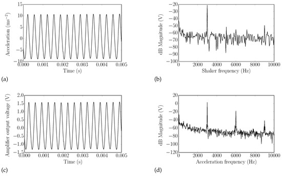
Figure 4.
(a) Acceleration signal recorded from the accelerometer, which was placed on a shaker. (b) Frequency spectrum of input signal to the shaker. (c) Measured output voltage from the amplifier. (d) Frequency spectrum of output voltage.
4. Conclusions
In this paper a self-powered accelerometer for high temperature applications is presented. A thermoelectric generator with internal cooling is tested and analysed for a given environmental temperature. A boost converter is used to convert the output voltage of the thermoelectric generator and the microprocessor used to convert the acceleration data and mange the duty cycles. These elements were all selected to operate at temperature above C as well as their low power consumption. It was demonstrated that the self-powered accelerometer can perform well in the regions close to resonance band and fault frequencies.
Funding
This study was carried out in the framework of Clean Sky 2 Joint Undertaking under the European Union Horizon 2020 research and innovation programme under grant agreement No I2BS: 717174.
Conflicts of Interest
The authors declare no conflict of interest.
References
- Zaghari, B.; Weddell, A.; White, N. Opportunities and challenges for energy harvesting sensor systems for harsh environments; ENSsys 2017: Delft, Netherlands, 2017. [Google Scholar]
- Rowe, D.M. CRC handbook of thermoelectrics; CRC press, 1995. [Google Scholar]
- Zaghari, B.; Weddell, A.; White, N.; Bashir, I.; Harvey, T.; Wang, L. Integrated smart bearings for next generation aero-engines.: Part II: energy harvesting and wireless communication development; First World Congress on Condition Monitoring: London, United Kingdom, 2017. [Google Scholar]
- Kambe, M.; Takahiro, J.; Zenzo, I. Encapsulated thermoelectric modules and compliant pads for advanced thermoelectric systems. Journal of electronic materials 2010, 39, 1418–1421. [Google Scholar] [CrossRef][Green Version]
- Kambe, M.; Morita, R.; Omoto, K.; Koji, Y.; Yoshida, T.; Noishiki, K. Thermoelectric Power Conversion System Combined with LNG Vaporizer. Journal of Power and Energy Systems 2008, 2, 1304–1319. [Google Scholar] [CrossRef][Green Version]
- Tandon, N.; Choudhury, A. A review of vibration and acoustic measurement methods for the detection of defects in rolling element bearings. Tribology international 1999, 32, 469–480. [Google Scholar] [CrossRef]


Publisher’s Note: MDPI stays neutral with regard to jurisdictional claims in published maps and institutional affiliations. |
© 2018 by the authors. Licensee MDPI, Basel, Switzerland. This article is an open access article distributed under the terms and conditions of the Creative Commons Attribution (CC BY) license (https://creativecommons.org/licenses/by/4.0/).